EP2904242B1 - Modellbasierte motoreinlasszustandsschätzung - Google Patents
Modellbasierte motoreinlasszustandsschätzung Download PDFInfo
- Publication number
- EP2904242B1 EP2904242B1 EP13866772.0A EP13866772A EP2904242B1 EP 2904242 B1 EP2904242 B1 EP 2904242B1 EP 13866772 A EP13866772 A EP 13866772A EP 2904242 B1 EP2904242 B1 EP 2904242B1
- Authority
- EP
- European Patent Office
- Prior art keywords
- engine
- inlet
- gas turbine
- sensed
- fault detection
- Prior art date
- Legal status (The legal status is an assumption and is not a legal conclusion. Google has not performed a legal analysis and makes no representation as to the accuracy of the status listed.)
- Active
Links
Images


Classifications
-
- G—PHYSICS
- G01—MEASURING; TESTING
- G01M—TESTING STATIC OR DYNAMIC BALANCE OF MACHINES OR STRUCTURES; TESTING OF STRUCTURES OR APPARATUS, NOT OTHERWISE PROVIDED FOR
- G01M15/00—Testing of engines
- G01M15/14—Testing gas-turbine engines or jet-propulsion engines
-
- G—PHYSICS
- G05—CONTROLLING; REGULATING
- G05B—CONTROL OR REGULATING SYSTEMS IN GENERAL; FUNCTIONAL ELEMENTS OF SUCH SYSTEMS; MONITORING OR TESTING ARRANGEMENTS FOR SUCH SYSTEMS OR ELEMENTS
- G05B23/00—Testing or monitoring of control systems or parts thereof
- G05B23/02—Electric testing or monitoring
- G05B23/0205—Electric testing or monitoring by means of a monitoring system capable of detecting and responding to faults
- G05B23/0218—Electric testing or monitoring by means of a monitoring system capable of detecting and responding to faults characterised by the fault detection method dealing with either existing or incipient faults
- G05B23/0243—Electric testing or monitoring by means of a monitoring system capable of detecting and responding to faults characterised by the fault detection method dealing with either existing or incipient faults model based detection method, e.g. first-principles knowledge model
- G05B23/0254—Electric testing or monitoring by means of a monitoring system capable of detecting and responding to faults characterised by the fault detection method dealing with either existing or incipient faults model based detection method, e.g. first-principles knowledge model based on a quantitative model, e.g. mathematical relationships between inputs and outputs; functions: observer, Kalman filter, residual calculation, Neural Networks
-
- G—PHYSICS
- G05—CONTROLLING; REGULATING
- G05B—CONTROL OR REGULATING SYSTEMS IN GENERAL; FUNCTIONAL ELEMENTS OF SUCH SYSTEMS; MONITORING OR TESTING ARRANGEMENTS FOR SUCH SYSTEMS OR ELEMENTS
- G05B23/00—Testing or monitoring of control systems or parts thereof
- G05B23/02—Electric testing or monitoring
- G05B23/0205—Electric testing or monitoring by means of a monitoring system capable of detecting and responding to faults
- G05B23/0259—Electric testing or monitoring by means of a monitoring system capable of detecting and responding to faults characterized by the response to fault detection
- G05B23/0297—Reconfiguration of monitoring system, e.g. use of virtual sensors; change monitoring method as a response to monitoring results
Definitions
- the present invention relates generally to gas turbine engine monitoring, and more particularly to a system of fault detection and accommodation for faults in engine inlet condition sensors.
- inlet pressure and temperature In aircraft gas turbine engines such as turbojets and turbofans, it is necessary to monitor inlet pressure and temperature in order to accurately control engine net thrust and manage compressor/combustor operability and hot section part life.
- inlet temperature and pressure readings are used to detect and avoid icing and other dangerous inlet conditions.
- Conventional aircraft gas turbine engine control systems include dedicated pressure and temperature sensors configured to monitor inlet conditions. Inlet condition sensor faults can give rise to false pressure and/or temperature readings that may lead to incorrect engine control resulting in failure to achieve required thrust, operability and/or life.
- US 2008/270003 A1 discloses a feedback control system and method, which implement a control law that receives sensed operational parameter feedback signals.
- the feedback signals that are supplied to the control law selectively comprise the sensor signal representative of the engine operational parameter if the sensor signal is valid, or an observer estimate of the sensed engine operational parameter if the sensor signal is invalid.
- US 6804600 B1 discloses a sensor error compensation system and method that facilitates improved sensor error detection and compensation.
- the sensor error compensation system includes an expected value generator and a sensor fault detector.
- the expected value generator receives sensor data from a plurality of sensors in a turbine engine. From the sensor data, the expected value generator generates an expected sensor value for a sensor under test. The expected sensor value is passed to the sensor fault detector.
- the sensor fault detector compares the expected sensor value to a received sensor value to determine if a sensor error has occurred in the sensor under test.
- the present invention is directed toward a gas turbine engine inlet sensor fault detection and accommodation system comprising an engine model, an engine parameter comparison block, an inlet condition estimator, control laws, and a fault detection and accommodation system.
- the engine model is configured to produce a real-time model-based estimate of engine parameters.
- the engine parameter comparison block is configured to produce residuals indicating the difference between the real-time model-based estimate of engine parameters and sensed values of the engine parameters.
- the inlet condition estimator is configured to iteratively adjust an estimate of inlet conditions based on the residuals.
- the control laws are configured to produce engine control parameters for control of gas turbine engine actuators based on the inlet conditions.
- the fault detection and accommodation system is configured to detect faults in inlet condition sensors, select sensed inlet conditions for use by the control laws in the event of no fault, and select estimated inlet conditions for use by the control laws in the event of inlet condition sensor fault.
- FIG. 1 is a cross-sectional view of gas turbine engine 10.
- Gas turbine engine 10 comprises compressor section 12, combustor 14, and turbine section 16 arranged in flow series between upstream inlet 18 and downstream exhaust 20.
- Compressor section 12 and turbine section 16 are arranged into a number of alternating stages of rotor airfoils (or blades) 22 and stator airfoils (or vanes) 24.
- propulsion fan 26 is positioned in bypass duct 28, which is coaxially oriented about the engine core along centerline (or turbine axis) C L .
- An open-rotor propulsion stage 26 may also be provided, with turbine engine 10 operating as a turboprop or unducted turbofan engine.
- fan rotor 26 and bypass duct 28 may be absent, with turbine engine 10 configured as a turbojet or turboshaft engine, or an industrial gas turbine.
- compressor section 12 includes low pressure compressor (LPC) 30 and high pressure compressor (HPC) 32, and turbine section 16 includes high pressure turbine (HPT) 34 and low pressure turbine (LPT) 36.
- Low pressure compressor 30 is rotationally coupled to low pressure turbine 36 via low pressure (LP) shaft 38, forming the LP spool or low spool.
- High pressure compressor 32 is rotationally coupled to high pressure turbine 34 via high pressure (HP) shaft 40, forming the HP spool or high spool.
- Flow F at inlet 18 divides into primary (core) flow F P and secondary (bypass) flow F S downstream of fan rotor 26.
- Fan rotor 26 accelerates secondary flow F S through bypass duct 28, with fan exit guide vanes (FEGVs) 42 to reduce swirl and improve thrust performance.
- FEGVs fan exit guide vanes
- structural guide vanes (SGVs) 42 are used, providing combined flow turning and load bearing capabilities.
- Primary flow F p at inlet 18 is characterized by inlet pressure P In and inlet temperature T In .
- Primary flow Fp is compressed in low pressure compressor 30 and high pressure compressor 32, then mixed with fuel in combustor 14 and ignited to generate hot combustion gas.
- the combustion gas expands to provide rotational energy in high pressure turbine 34 and low pressure turbine 36, driving high pressure compressor 32 and low pressure compressor 30, respectively.
- Expanded combustion gases exit through exhaust section (or exhaust nozzle) 20, which can be shaped or actuated to regulate the exhaust flow and improve thrust performance.
- Low pressure shaft 38 and high pressure shaft 40 are mounted coaxially about centerline C L , and rotate at different speeds.
- Fan rotor (or other propulsion stage) 26 is rotationally coupled to low pressure shaft 38.
- Fan rotor 26 may also function as a first-stage compressor for gas turbine engine 10, and LPC 30 may be configured as an intermediate compressor or booster.
- Gas turbine engine 10 may be embodied in a wide range of different shaft, spool and turbine engine configurations, including one, two and three-spool turboprop and (high or low bypass) turbofan engines, turboshaft engines, turbojet engines, and multi-spool industrial gas turbines.
- Engine control for gas turbine engine control relies on accurate measurements of a variety of engine and environmental parameters, including inlet pressure P In and inlet temperature T In .
- P In and T In may be used to retrieve control values or model constants from a lookup table for fuel flow metering, variable vane geometry actuation, and other controllable parameters.
- P In and T In may be inputs for real-time model-based control.
- Inlet pressure P In and inlet temperature T In may, for instance, be critical variables for predicting and avoiding compressor stall and combustor blowout.
- Inlet pressure P In and inlet temperature T In are measured by onboard sensors.
- Fault detection and accommodation system 100 detects faults in these sensors, and provides estimated values of inlet pressure P In and inlet temperature T In as a backup in case of sensor malfunction.
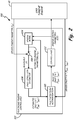
- FIG. 2 is a schematic block diagram of fault detection and accommodation system 100, comprising gas turbine engine 10 and electronic engine control 102 with engine model 104, engine parameter comparison block 106, inlet condition estimator 108, fault detection and accommodation block 110, and control laws 112.
- fault detection and accommodation system 100 allows the electronic engine control to identify and accommodate faults in inlet condition sensors such as pressure and temperature sensors.
- the logic flow paths indicated in FIG. 2 reflect one time step in an iteratively repeating real time control process.
- Electronic engine control system 102 is a digital controller that specifies engine control parameters ECP for actuator systems of gas turbine engine 10 according to control laws 112, and based on a plurality of sensed and/or estimated engine and environmental parameters including inlet pressure P In and inlet temperature T In .
- electronic engine control system 102 receives sensed values P InS and T InS of inlet pressure and temperature, respectively, and simultaneously produces estimates P InE and T InE of inlet pressure and temperature. These sensed and estimated values are compared to detect sensor faults, and estimated values are substituted for sensed values in the event of sensor failure.
- Electronic engine control system 102 is comprised of five sections: engine model 104, engine parameter comparison block 106, inlet condition estimator 108, fault detection and accommodation block 110, and control laws 112. These logic blocks represent distinct processes performed by electronic engine control 102, but may share common hardware.
- Engine model 104, engine parameter comparison block 106, inlet condition estimator 108, fault detection and accommodation block 110, and control laws 112 may be logically separable software algorithms running on a shared processor or multiple parallel processors of a full authority digital engine controller (FADEC) or other computing device.
- FADEC full authority digital engine controller
- Engine model 104 is a logical block incorporating a model of gas turbine engine 10.
- engine model 104 may be a component-level model describing only compressor section 12.
- engine model 104 may be a system-level model describing the entirety of gas turbine engine 10.
- Engine model 104 may, for instance, be constructed based on the assumption that specific heats and gas constants within gas turbine engine 10 remain constant over one timestep.
- engine model 104 may incorporate simplifying assumptions that unaccounted pressure losses across gas turbine engine 10 and torque produced by cooling bleed mass flow are negligible. The particular simplifying assumptions used by engine model 104 are selected for high accuracy during normal modes of operation of gas turbine engine 10, and may not hold during some exceptional operating conditions such as engine surge.
- Engine model 104 receives a plurality of engine parameter inputs including previous timestep estimates of inlet pressure P InE and inlet temperature T InE , and engine control parameters ECP corresponding to actuator states specified by control laws 112.
- Engine control parameters ECP may, for instance, include fuel flow rates into combustor 14, variable compressor bleed values, angle of attack on variable geometry compressor stator vanes, and variable nozzle area.
- Engine model 104 may also be programmed with installation inputs (not shown; e.g. bleeds for cabin cooling) that are substantially constant or independent of engine operation.
- Engine model 104 is a real time model describing relationships between these engine parameter inputs and a series of estimated engine parameters Y E .
- Engine model 104 may, for instance, be a piecewise linear state variable model or a component-level aerothermodynamic model.
- Estimated engine parameters Y E are generated in the form of a vector by engine model 104, and may comprise a mixture of unmodified engine parameter inputs and dependent variables estimated in real time based on engine parameter inputs using engine model 104.
- Estimated engine parameters Y E may, for instance, include rotor speeds of low pressure shaft 38 and high pressure shaft 40, pressure values at points within compressor section 12, and exhaust gas temperatures.
- Engine parameter comparison block 106 compares estimated engine parameters Y E from sensed engine parameters Y S to yield residuals r.
- Sensed engine parameters Y S parallel estimated engine parameters Y E , but are taken from appropriate sensors distributed within gas turbine engine 10.
- residuals r take the form of a vector comprising error values indicating a difference between estimated engine parameters Y E and sensed engine parameters Y S .
- initial estimates of P InE(last) and T InE(last) may be provided from a lookup table based, e.g., on altitude.
- gain vectors k P and k T are retrieved from a lookup table by one or more engine state parameters (e.g. a subset of sensed engine parameter Y S and/or estimated engine parameters Y E ). In other embodiments, gain vectors k P and k T are produced in real time by engine model 104.
- Fault detection and accommodation block 110 receives both estimated inlet pressure and temperature values P InE and T InE , and sensed inlet pressure and temperature values P InS and T InS , respectively. Fault detection and accommodation block 110 identifies probable sensor faults, selects either sensed or estimated inlet conditions based on the presence of absence of sensor fault conditions, and forwards selected sensed or estimated inlet pressure and temperature values to control laws 112. In particular, fault detection and accommodation block 110 selects and forwards sensed pressure and temperature values P InS and T InS whenever no fault is flagged, and forwards estimated pressure and temperature values P InE and T InE as backup values whenever a fault is flagged. Pressure and temperature values may be selected separately; fault detection and accommodation block 110 may, for instance, select and forward sensed inlet pressure P InS together with estimated inlet temperature T InS in the event of a temperature sensor fault.
- Fault detection and accommodation block 110 may identify sensor fault conditions in a variety of ways. In some embodiments, fault detection and accommodation block 110 flags a sensor fault if values of P InS and/or T InS values fall outside of absolute allowable ranges. In other embodiments, fault detection and accommodation block 110 flags a sensor fault if change in P InS and/or T InS between timesteps or across multiple timesteps exceeds a threshold value. Fault detection and accommodation block 110 may aggregate or average values or rates of change of P InS and/or T InS , and flag a fault if aggregated or average values fall outside of permissible ranges.
- permissible transient abnormalities in value or change in P InS and/or T InS may be greater in magnitude than permissible persistent deviations from expected values.
- fault limits for aggregate or average values may be stricter (i.e. narrower) than for instantaneous values.
- Fault detection and accommodation block 110 may additionally flag faults if absolute value or rate of change in sensed inlet pressure P InS and/or temperature T InS deviates from estimated inlet pressure and/or temperature P InE and/or T InE by more than a threshold value.
- fault detection and accommodation block 110 may flag faults if this deviation persists for multiple timesteps.
- Fault detection and accommodation block 110 may utilize any combination of the aforementioned fault detection methods.
- Control laws 112 specify engine control parameters ECP according to inlet pressure and temperature values selected by fault accommodation block 110 (i.e. P InE or P InS and T InE or T InE ). Control laws 112 may receive a wide variety of additional inputs reflecting other parameters of gas turbine engine 10, environmental parameters, and static or quasi-static calibration parameters.
- Engine control parameters ECP control actuators in gas turbine engine 10, including actuators of variable geometry stator vanes, variable bleed valves, and nozzles.
- Engine control parameters ECP are also forwarded to engine model 104 along with estimated inlet pressure and temperature P InE and T InE in preparation for producing estimated engine parameters Y E in the next timestep.
- FIG. 3 is a flowchart of fault detection and accommodation method 300, an exemplary method carried out by fault detection and accommodation system 100 to identify and accommodate faults in inlet pressure and temperature sensors.
- Fault detection and accommodation method 300 may be repeated many times during operation of fault detection and accommodation system 100.
- Method 300 differentiates between first and subsequent passes.
- engine model 104 is initialized using measured or approximate values of inlet pressure and temperature.
- Step S2 In subsequent iterations of method 300, engine model 104 is updated using engine control parameters ECP and inlet pressure and temperature estimates P InE and T InE produced in previous passes.
- ECP engine control parameters
- inlet pressure and temperature estimates P InE and T InE produced in previous passes.
- Engine model 104 produces estimated engine parameters Y E (Step S4), which are compared with corresponding sensed engine parameters T S to generate residuals r (Step S5).
- Inlet condition estimator 108 estimates inlet pressure and temperature values P InE and T InE by iteratively adjusting previous values using residuals r and gain vectors k P and k T , as described in Equations 1-4. (Step S6). For the first iteration of step S4, previous timestep pressure and temperature values P InE(last) and T InE(last) are approximated using a lookup table or fixed value based, e.g., on altitude. For subsequent iterations of step S4, the previous timestep estimate of P InE and T InE is used, instead.
- Fault detection and accommodation block 110 identifies faults in inlet pressure and temperature sensors based on values or rates of change of P InS and/or T InS , and/or based on comparison of sensed with estimated values.
- Step S7 Fault detection and accommodation block 110 forwards sensed or estimated values of inlet parameters to command laws 112, depending on sensor fault state. If fault detection and accommodation block 110 flags a fault in a sensor, the corresponding estimated value is selected for forwarding as a replacement. (Step S9). Otherwise, the sensed value is forwarded instead, as sensed values are ordinarily more accurate than estimated values.
- Control laws 112 compute engine control parameters ECP based on selected values of compressor inlet temperature and pressure. (Step S10). Engine control parameters ECP are used to actuate engine parameters as described above with respect to FIG. 2 . (Step S11).
- Fault detection and accommodation system 100 detects faults in compressor inlet condition sensors and provides backup estimated values of inlet pressure P In and inlet temperature T In for use in case of sensor malfunction. In this way, fault detection and accommodation system 100 allows gas turbine engine 10 to continue operating at substantially undiminished efficiency through sensor faults. Estimated inlet pressure and temperature P InE and T InE can also be used to increase the accuracy and reliability of sensor fault detection, as described above with respect to FIG. 1 , thereby reducing the probability of an undetected fault leading to incorrect control action.
Landscapes
- Engineering & Computer Science (AREA)
- Physics & Mathematics (AREA)
- General Physics & Mathematics (AREA)
- Automation & Control Theory (AREA)
- Chemical & Material Sciences (AREA)
- Combustion & Propulsion (AREA)
- Artificial Intelligence (AREA)
- Evolutionary Computation (AREA)
- Mathematical Physics (AREA)
- Control Of Turbines (AREA)
- Combined Controls Of Internal Combustion Engines (AREA)
Claims (15)
- Gasturbinenmotoreinlasssensor-Störungserkennungs- und - Akkommodationssystem (100), Folgendes umfassend:ein Triebwerksmodell (104), das dazu konfiguriert ist, eine modellbasierte Echtzeitschätzung der Triebwerksparameter herzustellen;ein Motorparameter-Vergleichsblock (106), der dazu konfiguriert ist, um Rückstände zu produzieren, die den Unterschied zwischen der modellbasierten Echtzeitschätzung der Triebwerksparameter und den Messwerten der Triebwerksparameter angibt;dadurch gekennzeichnet, dass es Folgendes umfasst:einen Einlasszustandsschätzer (108), der dazu konfiguriert ist, eine Schätzung der Einlasszustände basierend auf den Rückständen iterativ anzupassen;Steuerrechte (112), die dazu konfiguriert sind, Triebwerksteuerparameter für das Steuern von Gasturbinentriebwerkstellantrieben basierend auf den Einlassbedingungen herzustellen; sowie ein Störungserkennungs- und -Akkommodationssystem (110), das dazu konfiguriert ist, Störungen in den Einlasszustandssensoren zu erkennen, gemessene Einlasszustände für die Nutzung durch die Steuerrechte auszuwählen, wenn keine Störung vorliegt, und geschätzte Einlasszustände für die Nutzung durch die Steuerrechte auszuwählen, wenn eine Störung des Einlasszustandssensors vorliegt.
- Gasturbinentriebwerkeinlasssensor-Störungserkennungs- und Akkommodationssystem (100) nach Anspruch 1, wobei das Motormodell (104) dazu konfiguriert ist, modellbasierte Echtzeitschätzungen der Triebwerksparameter basierend auf einer vorhergehenden Iterationsschätzung der Einlasszustände und basierend auf den Motorsteuerparametern herzustellen.
- Gasturbinentriebwerkeinlasssensor-Störungserkennungs- und Akkommodationssystem (100) nach Anspruch 1 oder 2, wobei die Einlassbedingungen die Verdichtereinlasstemperatur und den Verdichtereinlassdruck umfassen.
- Gasturbinentriebwerkeinlasssensor-Störungserkennungs- und Akkommodationssystem (100) nach einem der vorstehenden Ansprüche, wobei das Triebwerkmodell (104) Triebwerksteuerparameter und Aktualisierungen für einen nächsten Zeitschritt anhand des Triebwerkmodells empfängt.
- Gasturbinentriebwerkeinlasssensor-Störungserkennungs- und Akkommodationssystem (100) nach einem der vorstehenden Ansprüche, wobei die Triebwerksteuerparameter mindestens eines von einer Rotordrehzahl, einem Brennkammerdruck und einer Abgastemperatur umfassen.
- Gasturbinentriebwerkeinlasssensor-Störungserkennungs- und Akkommodationssystem (100) nach einem der vorstehenden Ansprüche, wobei das Störungserkennungs- und Akkommodationssystem (110) Störungen erkennt, indem es eine Störung markiert, wenn ein Wert oder eine Änderungsrate eines Werts von mindestens einem der gemessenen Einlasszustände außerhalb eines spezifizierten Bereiches liegt.
- Gasturbinentriebwerkeinlasssensor-Störungserkennungs- und Akkommodationssystem (100) nach einem der vorstehenden Ansprüche, wobei das Störungserkennungs- und Akkommodationssystem (110) Störungen erkennt, indem es eine Störung markiert, wenn die gemessenen Einlasszustände um mehr als einen Schwellenwert von den geschätzten Einlasszuständen abweichen.
- Gasturbinentriebwerkeinlasssensor-Störungserkennungs- und Akkommodationssystem (100) nach einem der vorstehenden Ansprüche, wobei der Einlasszustandsschätzer (108) iterativ die Schätzung der Einlasszustände anpasst, indem er die Schätzung der Einlasszustände eines vorhergehenden Zeitschritts um eine Funktion der Rückstände und einer Echtzeitzunahme des Variablenvektors anpasst.
- Gasturbinentriebwerkeinlasssensor-Störungserkennungs- und Akkommodationssystem (100) nach Anspruch 8, wobei die Echtzeitzunahme des Variablenvektors aus einer Nachschlagetabelle entnommen wird.
- Gasturbinentriebwerkeinlasssensor-Störungserkennungs- und Akkommodationssystem (100) nach Anspruch 8, wobei die Echtzeitzunahme des Variablenvektors anhand des Triebwerkmodells geschätzt wird.
- Verfahren (300) für die Akkommodation von Störungen in Einlasssensoren auf einem Gasturbinentriebwerk, wobei das Verfahren Folgendes umfasst:das Messen der Triebwerkeinlasszustände an einem Einlass des Gasturbinentriebwerks;das Herstellen einer modellbasierten Echtzeitschätzung der Triebwerksparameter;das Herstellen von Rückständen, die den Unterschied zwischen der modellbasierten Echtzeitschätzung der Triebwerksparameter und der gemessenen Werte der Triebwerksparameter angeben;dadurch gekennzeichnet, dassein iteratives Anpassen einer Schätzung der Einlasszustände basierend auf den Rückständen vorgenommen wird;die Triebwerksteuerparameter für das Steuern der Gasturbinentriebwerkstellantriebe basierend auf den Einlasszuständen hergestellt werden;Störungen in den Einlasssensoren identifiziert werden; unddie geschätzten Triebwerkeinlasszustände genutzt werden, um Triebwerksteuerparameter im Falle einer Störung und andernfalls die gemessenen Triebwerkeinlasszustände herzustellen.
- Verfahren nach Anspruch 11, wobei das Identifizieren von Störungen in den Einlasssensoren das Markieren einer Störung umfasst, immer wenn ein Wert der gemessenen Triebwerkeinlassbedingungen oder eine Änderungsrate der gemessenen Triebwerkeinlassbedingungen außerhalb eines vorbestimmten Bereichs liegt, wobei, optional, das Identifizieren von Störungen in den Einlasssensoren das Markieren einer Störung umfasst, immer wenn ein Wert der gemessenen Triebwerkeinlassbedingungen oder eine Änderungsrate der gemessenen Triebwerkeinlassbedingungen außerhalb eines vorbestimmten Bereichs liegt, im Ganzen oder im Durchschnitt über mehrere Zeitschritte des Verfahrens hinweg.
- Verfahren nach Anspruch 11 oder 12, wobei das Identifizieren von Störungen in den Einlasssensoren das Markieren einer Störung umfasst, immer wenn sich ein Wert der gemessenen Triebwerkeinlasszustände von einem entsprechenden Wert der geschätzten Einlasszustände um mehr als einen vorbestimmten Betrag unterscheidet, wobei, optional, das Identifizieren von Störungen in den Einlasssensoren das Markieren einer Störung umfasst, immer wenn sich ein Wert der gemessenen Triebwerkeinlasszustände von einem entsprechenden Wert der geschätzten Einlasszustände um mehr als einen vorbestimmten Wert unterscheidet, im Ganzen oder im Durchschnitt über mehrere Zeitschritte des Verfahrens hinweg.
- Verfahren nach Anspruch 11, 12 oder 13, wobei die Gasturbinentriebwerkeinlasszustände die Gasturbinenverdichtereinlasstemperatur und der Gasturbinenverdichtereinlassdruck sind.
- Verfahren nach einem der Ansprüche 11 bis 14, wobei das iterative Herstellen einer modellbasierten Echtzeitschätzung der Triebwerkseinlassbedingungen das Bilden von Rückständen aus einem Unterschied zwischen den gemessenen Triebwerkparametern und den modellbasierten Echtzeitschätzungen der entsprechenden Triebwerksparameter sowie das Anpassen der Schätzungen der Einlasszustände der vorherigen Zeitschritte basierend auf den Rückständen und einer Vektorzunahme umfasst, wobei, optional, die Vektorzunahme in Echtzeit aus einer Nachschlagtabelle entnommen wird oder in Echtzeit anhand des Gasturbinentriebwerkmodells berechnet wird.
Applications Claiming Priority (2)
| Application Number | Priority Date | Filing Date | Title |
|---|---|---|---|
| US13/631,359 US8720258B2 (en) | 2012-09-28 | 2012-09-28 | Model based engine inlet condition estimation |
| PCT/US2013/061640 WO2014105232A2 (en) | 2012-09-28 | 2013-09-25 | Model based engine inlet condition estimation |
Publications (3)
| Publication Number | Publication Date |
|---|---|
| EP2904242A2 EP2904242A2 (de) | 2015-08-12 |
| EP2904242A4 EP2904242A4 (de) | 2016-11-23 |
| EP2904242B1 true EP2904242B1 (de) | 2019-11-13 |
Family
ID=50383973
Family Applications (1)
| Application Number | Title | Priority Date | Filing Date |
|---|---|---|---|
| EP13866772.0A Active EP2904242B1 (de) | 2012-09-28 | 2013-09-25 | Modellbasierte motoreinlasszustandsschätzung |
Country Status (4)
| Country | Link |
|---|---|
| US (1) | US8720258B2 (de) |
| EP (1) | EP2904242B1 (de) |
| CA (1) | CA2881700C (de) |
| WO (1) | WO2014105232A2 (de) |
Families Citing this family (45)
| Publication number | Priority date | Publication date | Assignee | Title |
|---|---|---|---|---|
| US20140053403A1 (en) * | 2012-08-22 | 2014-02-27 | General Electric Company | Method for extending an original service life of gas turbine components |
| US9540944B2 (en) * | 2012-09-28 | 2017-01-10 | United Technologies Corporation | Real time model based compressor control |
| US9535409B1 (en) * | 2012-10-26 | 2017-01-03 | Esolar Inc. | Advanced control of a multiple receiver concentrated solar power plant |
| WO2014143837A1 (en) | 2013-03-15 | 2014-09-18 | United Technologies Corporation | Compact aero-thermo model based engine material temperature control |
| FR3024434B1 (fr) * | 2014-07-29 | 2016-08-05 | Airbus Helicopters | Procede et dispositif de detection de givrage d'une entree d'air d'un turbomoteur |
| CN104608933B (zh) * | 2015-01-26 | 2017-09-15 | 哈尔滨飞机工业集团有限责任公司 | 一种发动机惯性分离器控制系统及其控制方法 |
| WO2016133578A2 (en) * | 2015-02-04 | 2016-08-25 | Sikorsky Aircraft Corporation | Estimating dynamic thrust or shaft power of an engine |
| US10746253B2 (en) | 2015-08-20 | 2020-08-18 | Sikorsky Aircraft Corporation | Vibration damping device for an elongated member |
| US10067033B2 (en) | 2015-10-26 | 2018-09-04 | General Electric Company | Systems and methods for in-cylinder pressure estimation using pressure wave modeling |
| US9587552B1 (en) | 2015-10-26 | 2017-03-07 | General Electric Company | Systems and methods for detecting anomalies at in-cylinder pressure sensors |
| CN105626270B (zh) * | 2015-12-29 | 2017-09-29 | 中国航空工业集团公司沈阳发动机设计研究所 | 一种涡扇发动机全权限控制系统容错方法 |
| US20170243413A1 (en) * | 2016-02-22 | 2017-08-24 | Hamilton Sundstrand Corporation | Method for determining aircraft sensor failure without a redundant sensor and correct sensor measurement when redundant aircraft sensors give inconsistent readings |
| US10294813B2 (en) | 2016-03-24 | 2019-05-21 | United Technologies Corporation | Geared unison ring for variable vane actuation |
| US10288087B2 (en) | 2016-03-24 | 2019-05-14 | United Technologies Corporation | Off-axis electric actuation for variable vanes |
| US10329946B2 (en) | 2016-03-24 | 2019-06-25 | United Technologies Corporation | Sliding gear actuation for variable vanes |
| US10415596B2 (en) | 2016-03-24 | 2019-09-17 | United Technologies Corporation | Electric actuation for variable vanes |
| US10190599B2 (en) | 2016-03-24 | 2019-01-29 | United Technologies Corporation | Drive shaft for remote variable vane actuation |
| US10443431B2 (en) | 2016-03-24 | 2019-10-15 | United Technologies Corporation | Idler gear connection for multi-stage variable vane actuation |
| US10443430B2 (en) | 2016-03-24 | 2019-10-15 | United Technologies Corporation | Variable vane actuation with rotating ring and sliding links |
| US10107130B2 (en) | 2016-03-24 | 2018-10-23 | United Technologies Corporation | Concentric shafts for remote independent variable vane actuation |
| US10458271B2 (en) | 2016-03-24 | 2019-10-29 | United Technologies Corporation | Cable drive system for variable vane operation |
| US10301962B2 (en) | 2016-03-24 | 2019-05-28 | United Technologies Corporation | Harmonic drive for shaft driving multiple stages of vanes via gears |
| US10329947B2 (en) | 2016-03-24 | 2019-06-25 | United Technologies Corporation | 35Geared unison ring for multi-stage variable vane actuation |
| US10345830B2 (en) | 2016-05-03 | 2019-07-09 | United Technologies Corporation | Thermal management system control and heat exchanger life extension |
| DE102016111902B4 (de) * | 2016-06-29 | 2024-08-01 | Deutsches Zentrum für Luft- und Raumfahrt e.V. | Verfahren und Assistenzsystem zur Detektion einer Flugleistungsdegradierung |
| EP3285177A1 (de) * | 2016-08-19 | 2018-02-21 | Siemens Aktiengesellschaft | Verfahren und system zur automatischen bestimmung einer fehlerbedingung eines technischen systems |
| US10372120B2 (en) | 2016-10-06 | 2019-08-06 | General Electric Company | Multi-layer anomaly detection framework |
| US10401881B2 (en) * | 2017-02-14 | 2019-09-03 | General Electric Company | Systems and methods for quantification of a gas turbine inlet filter blockage |
| FR3066755B1 (fr) | 2017-05-23 | 2019-06-07 | Airbus Operations | Procede et dispositif de surveillance et d'estimation de parametres relatifs au vol d'un aeronef. |
| GB2563242B (en) * | 2017-06-07 | 2020-01-29 | Ge Aviat Systems Ltd | A method and system for enabling component monitoring redundancy in a digital network of intelligent sensing devices |
| US11203950B2 (en) * | 2018-01-25 | 2021-12-21 | Raytheon Technologies Corporation | On-board estimator engine sensor fault accommodation in engine control |
| US10961921B2 (en) | 2018-09-19 | 2021-03-30 | Pratt & Whitney Canada Corp. | Model-based control system and method for a turboprop engine |
| US12180892B2 (en) | 2019-02-01 | 2024-12-31 | Rtx Corporation | Machine learned aero-thermodynamic engine inlet condition synthesis |
| US11047253B2 (en) | 2019-05-03 | 2021-06-29 | Raytheon Technologies Corporation | Model-based rotor speed keep out zone control |
| FR3101669B1 (fr) | 2019-10-07 | 2022-04-08 | Safran | Dispositif, procédé et programme d’ordinateur de suivi de moteur d’aéronef |
| US11371911B2 (en) * | 2019-12-20 | 2022-06-28 | Pratt & Whitney Canada Corp. | System and method for sensor fault management |
| US11905891B2 (en) | 2021-08-20 | 2024-02-20 | Rtx Corporation | On-board estimator effector drift detection in engine control |
| CN114035537B (zh) * | 2021-10-22 | 2024-03-01 | 上海发电设备成套设计研究院有限责任公司 | 一种燃气轮机控制系统综合诊断平台及方法 |
| US11859561B2 (en) | 2021-12-07 | 2024-01-02 | Pratt & Whitney Canada Corp. | Method and system for determining aircraft engine inlet total pressure |
| CN116927949A (zh) * | 2022-03-30 | 2023-10-24 | 中国航发商用航空发动机有限责任公司 | 航空发动机温度传感器结冰检测系统及方法、存储介质 |
| US12055095B1 (en) * | 2023-05-12 | 2024-08-06 | Pratt & Whitney Canada Corp. | System and method for identifying blockage of an air intake for an aircraft propulsion system |
| CN116792209B (zh) * | 2023-06-25 | 2024-09-17 | 中国航发湖南动力机械研究所 | 涡轴发动机大气温度信号全故障的故障处理方法及系统 |
| CN120830559A (zh) | 2024-04-18 | 2025-10-24 | 通用电气技术有限公司 | 涡轮机功率增大特征部和方法 |
| US12196140B1 (en) | 2024-04-18 | 2025-01-14 | Ge Infrastructure Technology Llc | Inlet conditioning systems and methods for a turbomachine |
| DE102024115037B3 (de) * | 2024-05-29 | 2025-10-16 | Deutsches Zentrum für Luft- und Raumfahrt e.V. | Verfahren zur Detektion einer Luftfahrzeugvereisung sowie Vorrichtung und Luftfahrzeug hierzu |
Family Cites Families (25)
| Publication number | Priority date | Publication date | Assignee | Title |
|---|---|---|---|---|
| US4423594A (en) * | 1981-06-01 | 1984-01-03 | United Technologies Corporation | Adaptive self-correcting control system |
| US4490791A (en) * | 1982-04-19 | 1984-12-25 | Chandler Evans Inc. | Adaptive gas turbine acceleration control |
| US6598195B1 (en) * | 2000-08-21 | 2003-07-22 | General Electric Company | Sensor fault detection, isolation and accommodation |
| JP4230356B2 (ja) * | 2001-11-15 | 2009-02-25 | グッドリッチ・ポンプ・アンド・エンジン・コントロール・システムズ・インコーポレーテッド | ガスタービンエンジン制御システムに加速計画を適用するための方法および装置 |
| US7216071B2 (en) | 2002-04-23 | 2007-05-08 | United Technologies Corporation | Hybrid gas turbine engine state variable model |
| US7219040B2 (en) | 2002-11-05 | 2007-05-15 | General Electric Company | Method and system for model based control of heavy duty gas turbine |
| US6823675B2 (en) * | 2002-11-13 | 2004-11-30 | General Electric Company | Adaptive model-based control systems and methods for controlling a gas turbine |
| US6804600B1 (en) | 2003-09-05 | 2004-10-12 | Honeywell International, Inc. | Sensor error detection and compensation system and method |
| US20050193739A1 (en) | 2004-03-02 | 2005-09-08 | General Electric Company | Model-based control systems and methods for gas turbine engines |
| EP1705542B1 (de) * | 2005-03-24 | 2008-08-06 | Abb Research Ltd. | Abschätzen der Zustandparameter oder Erscheinung eines alternden Systems |
| US7603222B2 (en) * | 2005-11-18 | 2009-10-13 | General Electric Company | Sensor diagnostics using embedded model quality parameters |
| US7837429B2 (en) | 2006-10-12 | 2010-11-23 | General Electric Company | Predictive model based control system for heavy duty gas turbines |
| US9043118B2 (en) | 2007-04-02 | 2015-05-26 | General Electric Company | Methods and systems for model-based control of gas turbines |
| US7630820B2 (en) * | 2007-04-24 | 2009-12-08 | Honeywell International Inc. | Feedback control system and method that selectively utilizes observer estimates |
| US7908072B2 (en) * | 2007-06-26 | 2011-03-15 | General Electric Company | Systems and methods for using a combustion dynamics tuning algorithm with a multi-can combustor |
| US20090043447A1 (en) * | 2007-08-07 | 2009-02-12 | General Electric Company | Systems and Methods for Model-Based Sensor Fault Detection and Isolation |
| US7822512B2 (en) | 2008-01-08 | 2010-10-26 | General Electric Company | Methods and systems for providing real-time comparison with an alternate control strategy for a turbine |
| EP2342609B1 (de) * | 2008-10-03 | 2015-03-04 | Bell Helicopter Textron Inc. | Verfahren und vorrichtung für flugzeugsensoren- und betätigungsfehlerschutz mittels rekonfigurierbarer flugsteuerungsrichtlinien |
| US8131384B2 (en) * | 2008-11-03 | 2012-03-06 | United Technologies Corporation | Design and control of engineering systems utilizing component-level dynamic mathematical model with multiple-input multiple-output estimator |
| US8090456B2 (en) * | 2008-11-03 | 2012-01-03 | United Technologies Corporation | System and method for design and control of engineering systems utilizing component-level dynamic mathematical model |
| US8668434B2 (en) * | 2009-09-02 | 2014-03-11 | United Technologies Corporation | Robust flow parameter model for component-level dynamic turbine system control |
| US8315741B2 (en) * | 2009-09-02 | 2012-11-20 | United Technologies Corporation | High fidelity integrated heat transfer and clearance in component-level dynamic turbine system control |
| US8215095B2 (en) | 2009-10-26 | 2012-07-10 | General Electric Company | Model-based coordinated air-fuel control for a gas turbine |
| US8171717B2 (en) | 2010-05-14 | 2012-05-08 | General Electric Company | Model-based coordinated air-fuel control for a gas turbine |
| US9342060B2 (en) | 2010-09-14 | 2016-05-17 | United Technologies Corporation | Adaptive control for a gas turbine engine |
-
2012
- 2012-09-28 US US13/631,359 patent/US8720258B2/en active Active
-
2013
- 2013-09-25 WO PCT/US2013/061640 patent/WO2014105232A2/en not_active Ceased
- 2013-09-25 EP EP13866772.0A patent/EP2904242B1/de active Active
- 2013-09-25 CA CA2881700A patent/CA2881700C/en active Active
Non-Patent Citations (1)
| Title |
|---|
| None * |
Also Published As
| Publication number | Publication date |
|---|---|
| US20140090456A1 (en) | 2014-04-03 |
| EP2904242A4 (de) | 2016-11-23 |
| WO2014105232A2 (en) | 2014-07-03 |
| CA2881700C (en) | 2021-01-26 |
| EP2904242A2 (de) | 2015-08-12 |
| WO2014105232A3 (en) | 2014-09-18 |
| CA2881700A1 (en) | 2014-07-03 |
| US8720258B2 (en) | 2014-05-13 |
Similar Documents
| Publication | Publication Date | Title |
|---|---|---|
| EP2904242B1 (de) | Modellbasierte motoreinlasszustandsschätzung | |
| US20250320832A1 (en) | Machine learned aero-thermodynamic engine inlet condition synthesis | |
| EP2900986B1 (de) | Echtzeit-modellbasierte verdichtersteuerung | |
| EP3284930B1 (de) | Gasturbine mit leckerkennung sowie verfahren | |
| EP2149824B1 (de) | Verfahren und Systeme zur Schätzung der Betriebsparameter eines Motors | |
| EP2900985B1 (de) | Modellbasierte steuerung des kraftstoff-luftverhältnisses | |
| US10196928B2 (en) | Method and system for piping failure detection in a gas turbine bleeding air system | |
| US10801359B2 (en) | Method and system for identifying rub events | |
| EP3173890B1 (de) | Fehlerdetektionsverfahren und -systeme | |
| EP3712737B1 (de) | Signalantwortüberwachung für turbinenmotoren | |
| EP4345258A1 (de) | Systeme und verfahren zur bestimmung von gasturbinenmotortemperaturen | |
| EP4461650A1 (de) | System und verfahren zur erkennung der blockierung eines lufteinlasses für ein flugzeugantriebssystem | |
| US20240060426A1 (en) | Systems and methods for determining gas turbine engine operating margins | |
| May et al. | Engine icing modeling and simulation (Part 2): Performance simulation of engine rollback phenomena | |
| Ebmeyer et al. | Evaluation of total engine performance degradation based on modular efficiencies | |
| US12392255B2 (en) | Systems and methods for determining gas turbine engine operating margins | |
| Xia | Engine health monitoring based on remote diagnostics | |
| CHAMBLEE et al. | Effectiveness of turbine engine diagnostic systems |
Legal Events
| Date | Code | Title | Description |
|---|---|---|---|
| PUAI | Public reference made under article 153(3) epc to a published international application that has entered the european phase |
Free format text: ORIGINAL CODE: 0009012 |
|
| 17P | Request for examination filed |
Effective date: 20150423 |
|
| AK | Designated contracting states |
Kind code of ref document: A2 Designated state(s): AL AT BE BG CH CY CZ DE DK EE ES FI FR GB GR HR HU IE IS IT LI LT LU LV MC MK MT NL NO PL PT RO RS SE SI SK SM TR |
|
| AX | Request for extension of the european patent |
Extension state: BA ME |
|
| RIN1 | Information on inventor provided before grant (corrected) |
Inventor name: KARPMAN, BORIS Inventor name: POTH, JR., STEFAN M. Inventor name: BRITTEN, ALEXANDRA I. Inventor name: MEISNER, RICHARD P. |
|
| DAX | Request for extension of the european patent (deleted) | ||
| REG | Reference to a national code |
Ref country code: DE Ref legal event code: R079 Ref document number: 602013062983 Country of ref document: DE Free format text: PREVIOUS MAIN CLASS: F02C0009000000 Ipc: G01M0015140000 |
|
| RAP1 | Party data changed (applicant data changed or rights of an application transferred) |
Owner name: UNITED TECHNOLOGIES CORPORATION |
|
| A4 | Supplementary search report drawn up and despatched |
Effective date: 20161026 |
|
| RIC1 | Information provided on ipc code assigned before grant |
Ipc: G01M 15/14 20060101AFI20161020BHEP Ipc: G05B 23/02 20060101ALI20161020BHEP Ipc: G05B 9/02 20060101ALI20161020BHEP |
|
| GRAP | Despatch of communication of intention to grant a patent |
Free format text: ORIGINAL CODE: EPIDOSNIGR1 |
|
| STAA | Information on the status of an ep patent application or granted ep patent |
Free format text: STATUS: GRANT OF PATENT IS INTENDED |
|
| INTG | Intention to grant announced |
Effective date: 20190522 |
|
| GRAS | Grant fee paid |
Free format text: ORIGINAL CODE: EPIDOSNIGR3 |
|
| GRAA | (expected) grant |
Free format text: ORIGINAL CODE: 0009210 |
|
| STAA | Information on the status of an ep patent application or granted ep patent |
Free format text: STATUS: THE PATENT HAS BEEN GRANTED |
|
| AK | Designated contracting states |
Kind code of ref document: B1 Designated state(s): AL AT BE BG CH CY CZ DE DK EE ES FI FR GB GR HR HU IE IS IT LI LT LU LV MC MK MT NL NO PL PT RO RS SE SI SK SM TR |
|
| REG | Reference to a national code |
Ref country code: CH Ref legal event code: EP Ref country code: AT Ref legal event code: REF Ref document number: 1202171 Country of ref document: AT Kind code of ref document: T Effective date: 20191115 |
|
| REG | Reference to a national code |
Ref country code: DE Ref legal event code: R096 Ref document number: 602013062983 Country of ref document: DE |
|
| REG | Reference to a national code |
Ref country code: IE Ref legal event code: FG4D |
|
| REG | Reference to a national code |
Ref country code: NL Ref legal event code: MP Effective date: 20191113 |
|
| REG | Reference to a national code |
Ref country code: LT Ref legal event code: MG4D |
|
| PG25 | Lapsed in a contracting state [announced via postgrant information from national office to epo] |
Ref country code: BG Free format text: LAPSE BECAUSE OF FAILURE TO SUBMIT A TRANSLATION OF THE DESCRIPTION OR TO PAY THE FEE WITHIN THE PRESCRIBED TIME-LIMIT Effective date: 20200213 Ref country code: FI Free format text: LAPSE BECAUSE OF FAILURE TO SUBMIT A TRANSLATION OF THE DESCRIPTION OR TO PAY THE FEE WITHIN THE PRESCRIBED TIME-LIMIT Effective date: 20191113 Ref country code: GR Free format text: LAPSE BECAUSE OF FAILURE TO SUBMIT A TRANSLATION OF THE DESCRIPTION OR TO PAY THE FEE WITHIN THE PRESCRIBED TIME-LIMIT Effective date: 20200214 Ref country code: NO Free format text: LAPSE BECAUSE OF FAILURE TO SUBMIT A TRANSLATION OF THE DESCRIPTION OR TO PAY THE FEE WITHIN THE PRESCRIBED TIME-LIMIT Effective date: 20200213 Ref country code: PL Free format text: LAPSE BECAUSE OF FAILURE TO SUBMIT A TRANSLATION OF THE DESCRIPTION OR TO PAY THE FEE WITHIN THE PRESCRIBED TIME-LIMIT Effective date: 20191113 Ref country code: PT Free format text: LAPSE BECAUSE OF FAILURE TO SUBMIT A TRANSLATION OF THE DESCRIPTION OR TO PAY THE FEE WITHIN THE PRESCRIBED TIME-LIMIT Effective date: 20200313 Ref country code: SE Free format text: LAPSE BECAUSE OF FAILURE TO SUBMIT A TRANSLATION OF THE DESCRIPTION OR TO PAY THE FEE WITHIN THE PRESCRIBED TIME-LIMIT Effective date: 20191113 Ref country code: LV Free format text: LAPSE BECAUSE OF FAILURE TO SUBMIT A TRANSLATION OF THE DESCRIPTION OR TO PAY THE FEE WITHIN THE PRESCRIBED TIME-LIMIT Effective date: 20191113 Ref country code: LT Free format text: LAPSE BECAUSE OF FAILURE TO SUBMIT A TRANSLATION OF THE DESCRIPTION OR TO PAY THE FEE WITHIN THE PRESCRIBED TIME-LIMIT Effective date: 20191113 Ref country code: NL Free format text: LAPSE BECAUSE OF FAILURE TO SUBMIT A TRANSLATION OF THE DESCRIPTION OR TO PAY THE FEE WITHIN THE PRESCRIBED TIME-LIMIT Effective date: 20191113 |
|
| PG25 | Lapsed in a contracting state [announced via postgrant information from national office to epo] |
Ref country code: IS Free format text: LAPSE BECAUSE OF FAILURE TO SUBMIT A TRANSLATION OF THE DESCRIPTION OR TO PAY THE FEE WITHIN THE PRESCRIBED TIME-LIMIT Effective date: 20200313 Ref country code: HR Free format text: LAPSE BECAUSE OF FAILURE TO SUBMIT A TRANSLATION OF THE DESCRIPTION OR TO PAY THE FEE WITHIN THE PRESCRIBED TIME-LIMIT Effective date: 20191113 Ref country code: RS Free format text: LAPSE BECAUSE OF FAILURE TO SUBMIT A TRANSLATION OF THE DESCRIPTION OR TO PAY THE FEE WITHIN THE PRESCRIBED TIME-LIMIT Effective date: 20191113 |
|
| PG25 | Lapsed in a contracting state [announced via postgrant information from national office to epo] |
Ref country code: AL Free format text: LAPSE BECAUSE OF FAILURE TO SUBMIT A TRANSLATION OF THE DESCRIPTION OR TO PAY THE FEE WITHIN THE PRESCRIBED TIME-LIMIT Effective date: 20191113 |
|
| PG25 | Lapsed in a contracting state [announced via postgrant information from national office to epo] |
Ref country code: DK Free format text: LAPSE BECAUSE OF FAILURE TO SUBMIT A TRANSLATION OF THE DESCRIPTION OR TO PAY THE FEE WITHIN THE PRESCRIBED TIME-LIMIT Effective date: 20191113 Ref country code: ES Free format text: LAPSE BECAUSE OF FAILURE TO SUBMIT A TRANSLATION OF THE DESCRIPTION OR TO PAY THE FEE WITHIN THE PRESCRIBED TIME-LIMIT Effective date: 20191113 Ref country code: EE Free format text: LAPSE BECAUSE OF FAILURE TO SUBMIT A TRANSLATION OF THE DESCRIPTION OR TO PAY THE FEE WITHIN THE PRESCRIBED TIME-LIMIT Effective date: 20191113 Ref country code: RO Free format text: LAPSE BECAUSE OF FAILURE TO SUBMIT A TRANSLATION OF THE DESCRIPTION OR TO PAY THE FEE WITHIN THE PRESCRIBED TIME-LIMIT Effective date: 20191113 Ref country code: CZ Free format text: LAPSE BECAUSE OF FAILURE TO SUBMIT A TRANSLATION OF THE DESCRIPTION OR TO PAY THE FEE WITHIN THE PRESCRIBED TIME-LIMIT Effective date: 20191113 |
|
| REG | Reference to a national code |
Ref country code: DE Ref legal event code: R097 Ref document number: 602013062983 Country of ref document: DE |
|
| REG | Reference to a national code |
Ref country code: AT Ref legal event code: MK05 Ref document number: 1202171 Country of ref document: AT Kind code of ref document: T Effective date: 20191113 |
|
| PG25 | Lapsed in a contracting state [announced via postgrant information from national office to epo] |
Ref country code: SM Free format text: LAPSE BECAUSE OF FAILURE TO SUBMIT A TRANSLATION OF THE DESCRIPTION OR TO PAY THE FEE WITHIN THE PRESCRIBED TIME-LIMIT Effective date: 20191113 Ref country code: SK Free format text: LAPSE BECAUSE OF FAILURE TO SUBMIT A TRANSLATION OF THE DESCRIPTION OR TO PAY THE FEE WITHIN THE PRESCRIBED TIME-LIMIT Effective date: 20191113 |
|
| PLBE | No opposition filed within time limit |
Free format text: ORIGINAL CODE: 0009261 |
|
| STAA | Information on the status of an ep patent application or granted ep patent |
Free format text: STATUS: NO OPPOSITION FILED WITHIN TIME LIMIT |
|
| 26N | No opposition filed |
Effective date: 20200814 |
|
| PG25 | Lapsed in a contracting state [announced via postgrant information from national office to epo] |
Ref country code: AT Free format text: LAPSE BECAUSE OF FAILURE TO SUBMIT A TRANSLATION OF THE DESCRIPTION OR TO PAY THE FEE WITHIN THE PRESCRIBED TIME-LIMIT Effective date: 20191113 Ref country code: SI Free format text: LAPSE BECAUSE OF FAILURE TO SUBMIT A TRANSLATION OF THE DESCRIPTION OR TO PAY THE FEE WITHIN THE PRESCRIBED TIME-LIMIT Effective date: 20191113 |
|
| PG25 | Lapsed in a contracting state [announced via postgrant information from national office to epo] |
Ref country code: IT Free format text: LAPSE BECAUSE OF FAILURE TO SUBMIT A TRANSLATION OF THE DESCRIPTION OR TO PAY THE FEE WITHIN THE PRESCRIBED TIME-LIMIT Effective date: 20191113 |
|
| PG25 | Lapsed in a contracting state [announced via postgrant information from national office to epo] |
Ref country code: MC Free format text: LAPSE BECAUSE OF FAILURE TO SUBMIT A TRANSLATION OF THE DESCRIPTION OR TO PAY THE FEE WITHIN THE PRESCRIBED TIME-LIMIT Effective date: 20191113 |
|
| REG | Reference to a national code |
Ref country code: CH Ref legal event code: PL |
|
| REG | Reference to a national code |
Ref country code: BE Ref legal event code: MM Effective date: 20200930 |
|
| PG25 | Lapsed in a contracting state [announced via postgrant information from national office to epo] |
Ref country code: LU Free format text: LAPSE BECAUSE OF NON-PAYMENT OF DUE FEES Effective date: 20200925 |
|
| PG25 | Lapsed in a contracting state [announced via postgrant information from national office to epo] |
Ref country code: CH Free format text: LAPSE BECAUSE OF NON-PAYMENT OF DUE FEES Effective date: 20200930 Ref country code: BE Free format text: LAPSE BECAUSE OF NON-PAYMENT OF DUE FEES Effective date: 20200930 Ref country code: IE Free format text: LAPSE BECAUSE OF NON-PAYMENT OF DUE FEES Effective date: 20200925 Ref country code: LI Free format text: LAPSE BECAUSE OF NON-PAYMENT OF DUE FEES Effective date: 20200930 |
|
| PG25 | Lapsed in a contracting state [announced via postgrant information from national office to epo] |
Ref country code: TR Free format text: LAPSE BECAUSE OF FAILURE TO SUBMIT A TRANSLATION OF THE DESCRIPTION OR TO PAY THE FEE WITHIN THE PRESCRIBED TIME-LIMIT Effective date: 20191113 Ref country code: MT Free format text: LAPSE BECAUSE OF FAILURE TO SUBMIT A TRANSLATION OF THE DESCRIPTION OR TO PAY THE FEE WITHIN THE PRESCRIBED TIME-LIMIT Effective date: 20191113 Ref country code: CY Free format text: LAPSE BECAUSE OF FAILURE TO SUBMIT A TRANSLATION OF THE DESCRIPTION OR TO PAY THE FEE WITHIN THE PRESCRIBED TIME-LIMIT Effective date: 20191113 |
|
| PG25 | Lapsed in a contracting state [announced via postgrant information from national office to epo] |
Ref country code: MK Free format text: LAPSE BECAUSE OF FAILURE TO SUBMIT A TRANSLATION OF THE DESCRIPTION OR TO PAY THE FEE WITHIN THE PRESCRIBED TIME-LIMIT Effective date: 20191113 |
|
| P01 | Opt-out of the competence of the unified patent court (upc) registered |
Effective date: 20230520 |
|
| REG | Reference to a national code |
Ref country code: DE Ref legal event code: R081 Ref document number: 602013062983 Country of ref document: DE Owner name: RTX CORPORATION (N.D.GES.D. STAATES DELAWARE),, US Free format text: FORMER OWNER: UNITED TECHNOLOGIES CORPORATION, FARMINGTON, CONN., US |
|
| PGFP | Annual fee paid to national office [announced via postgrant information from national office to epo] |
Ref country code: DE Payment date: 20250820 Year of fee payment: 13 |
|
| PGFP | Annual fee paid to national office [announced via postgrant information from national office to epo] |
Ref country code: GB Payment date: 20250822 Year of fee payment: 13 |
|
| PGFP | Annual fee paid to national office [announced via postgrant information from national office to epo] |
Ref country code: FR Payment date: 20250821 Year of fee payment: 13 |