EP2904287B1 - Dämpfer - Google Patents
Dämpfer Download PDFInfo
- Publication number
- EP2904287B1 EP2904287B1 EP13776908.9A EP13776908A EP2904287B1 EP 2904287 B1 EP2904287 B1 EP 2904287B1 EP 13776908 A EP13776908 A EP 13776908A EP 2904287 B1 EP2904287 B1 EP 2904287B1
- Authority
- EP
- European Patent Office
- Prior art keywords
- damper
- component
- bumper
- holes
- jounce
- Prior art date
- Legal status (The legal status is an assumption and is not a legal conclusion. Google has not performed a legal analysis and makes no representation as to the accuracy of the status listed.)
- Active
Links
Images


Classifications
-
- B—PERFORMING OPERATIONS; TRANSPORTING
- B60—VEHICLES IN GENERAL
- B60G—VEHICLE SUSPENSION ARRANGEMENTS
- B60G11/00—Resilient suspensions characterised by arrangement, location or kind of springs
- B60G11/22—Resilient suspensions characterised by arrangement, location or kind of springs having rubber springs only
-
- F—MECHANICAL ENGINEERING; LIGHTING; HEATING; WEAPONS; BLASTING
- F16—ENGINEERING ELEMENTS AND UNITS; GENERAL MEASURES FOR PRODUCING AND MAINTAINING EFFECTIVE FUNCTIONING OF MACHINES OR INSTALLATIONS; THERMAL INSULATION IN GENERAL
- F16F—SPRINGS; SHOCK-ABSORBERS; MEANS FOR DAMPING VIBRATION
- F16F1/00—Springs
- F16F1/36—Springs made of rubber or other material having high internal friction, e.g. thermoplastic elastomers
- F16F1/373—Springs made of rubber or other material having high internal friction, e.g. thermoplastic elastomers characterised by having a particular shape
- F16F1/377—Springs made of rubber or other material having high internal friction, e.g. thermoplastic elastomers characterised by having a particular shape having holes or openings
-
- F—MECHANICAL ENGINEERING; LIGHTING; HEATING; WEAPONS; BLASTING
- F16—ENGINEERING ELEMENTS AND UNITS; GENERAL MEASURES FOR PRODUCING AND MAINTAINING EFFECTIVE FUNCTIONING OF MACHINES OR INSTALLATIONS; THERMAL INSULATION IN GENERAL
- F16F—SPRINGS; SHOCK-ABSORBERS; MEANS FOR DAMPING VIBRATION
- F16F3/00—Spring units consisting of several springs, e.g. for obtaining a desired spring characteristic
- F16F3/08—Spring units consisting of several springs, e.g. for obtaining a desired spring characteristic with springs made of a material having high internal friction, e.g. rubber
- F16F3/087—Units comprising several springs made of plastics or the like material
- F16F3/093—Units comprising several springs made of plastics or the like material the springs being of different materials, e.g. having different types of rubber
-
- B—PERFORMING OPERATIONS; TRANSPORTING
- B60—VEHICLES IN GENERAL
- B60G—VEHICLE SUSPENSION ARRANGEMENTS
- B60G2202/00—Indexing codes relating to the type of spring, damper or actuator
- B60G2202/10—Type of spring
- B60G2202/14—Plastic spring, e.g. rubber
- B60G2202/143—Plastic spring, e.g. rubber subjected to compression
-
- B—PERFORMING OPERATIONS; TRANSPORTING
- B60—VEHICLES IN GENERAL
- B60G—VEHICLE SUSPENSION ARRANGEMENTS
- B60G2204/00—Indexing codes related to suspensions per se or to auxiliary parts
- B60G2204/40—Auxiliary suspension parts; Adjustment of suspensions
- B60G2204/45—Stops limiting travel
- B60G2204/4502—Stops limiting travel using resilient buffer
- B60G2204/45021—Stops limiting travel using resilient buffer for limiting upper mount movement of a McPherson strut
-
- B—PERFORMING OPERATIONS; TRANSPORTING
- B60—VEHICLES IN GENERAL
- B60G—VEHICLE SUSPENSION ARRANGEMENTS
- B60G2206/00—Indexing codes related to the manufacturing of suspensions: constructional features, the materials used, procedures or tools
- B60G2206/01—Constructional features of suspension elements, e.g. arms, dampers, springs
- B60G2206/70—Materials used in suspensions
- B60G2206/73—Rubber; Elastomers
-
- B—PERFORMING OPERATIONS; TRANSPORTING
- B60—VEHICLES IN GENERAL
- B60G—VEHICLE SUSPENSION ARRANGEMENTS
- B60G2500/00—Indexing codes relating to the regulated action or device
- B60G2500/20—Spring action or springs
-
- F—MECHANICAL ENGINEERING; LIGHTING; HEATING; WEAPONS; BLASTING
- F16—ENGINEERING ELEMENTS AND UNITS; GENERAL MEASURES FOR PRODUCING AND MAINTAINING EFFECTIVE FUNCTIONING OF MACHINES OR INSTALLATIONS; THERMAL INSULATION IN GENERAL
- F16F—SPRINGS; SHOCK-ABSORBERS; MEANS FOR DAMPING VIBRATION
- F16F2224/00—Materials; Material properties
- F16F2224/02—Materials; Material properties solids
- F16F2224/025—Elastomers
-
- F—MECHANICAL ENGINEERING; LIGHTING; HEATING; WEAPONS; BLASTING
- F16—ENGINEERING ELEMENTS AND UNITS; GENERAL MEASURES FOR PRODUCING AND MAINTAINING EFFECTIVE FUNCTIONING OF MACHINES OR INSTALLATIONS; THERMAL INSULATION IN GENERAL
- F16F—SPRINGS; SHOCK-ABSORBERS; MEANS FOR DAMPING VIBRATION
- F16F2236/00—Mode of stressing of basic spring or damper elements or devices incorporating such elements
- F16F2236/04—Compression
Definitions
- the present invention generally relates to a damper for use with a vehicle.
- US 2010/230877 A1 discloses an impact bumper assembly of the related art.
- a suspension system of a vehicle limits transmission of an impact force from tires to the frame of the vehicle. For example, when the vehicle travels over a bump, components of the suspension system jounce or collapse to absorb energy generated by the impact. However, when the suspension system cannot completely dissipate the energy, the components of the suspension system may impact each other thereby transmitting the forces to the frame, which is not desirable. Therefore, there is a need to prevent the components from impacting each other to prevent transmission of the remaining impact force from the tires to the frame of the vehicle.
- a damper absorbs energy generated between a first component and a second component.
- the second component is spaced from and moveable toward the first component along a jounce axis.
- the damper includes a body having a ring-shaped configuration.
- the body also includes a first edge for engaging the first component and a second edge for engaging the second component.
- the second edge is spaced from the first edge.
- the body defines a plurality of holes spaced about the body.
- the plurality of holes are configured to allow the damper to compress axially for absorbing energy as one of the first and second components move along the jounce axis.
- the plurality of holes converges toward a center point of the damper.
- the body has an exterior surface and an interior surface spaced from the exterior surface. An area of each of said holes at said exterior surface is larger than an area of each of said hole at said interior surface. Absorbing energy limits jounce travel and prevents the second component from directly impacting the first component, which can damage the components.
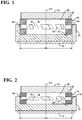
- a damper is generally shown at 20.
- the damper 20 is used between two components that move towards each other to prevent the components from directly impacting each other.
- the damper 20 is an intermediate cushion between a first component 22 and a second component 24, which is movable toward the first component 22 along a jounce axis JA.
- the damper 20 is compressed between the first and second components 22, 24 as the first and second components 22, 24 move toward each other, as shown in Figure 2 .
- the first and second components 22, 24 are part of a vehicle, such as a truck or a car. As the vehicle travels over a bump or hits on obstruction, such as a curb, the second component 24 jounces toward the first component 22 as a result of an impact force applied to tires of the vehicle. If the impact force is large enough, the second component 24 may contact the first component 22, which can damage either the first and second components 22, 24 or other components of the vehicle.
- the damper 20 is positioned between the first and second components 22, 24 to absorb energy as one of the first and second components 22, 24 moves along a jounce axis JA toward each other prevent the second component 24 from directly impacting the first component 22. Absorbing energy as one of the first and second components 22, 24 moves along a jounce axis JA toward each other limits jounce travel and prevents the first and second components 22, 24 from directly impacting each other, which can damage the first and second components 22, 24.
- the second component 24 is spaced from the first component 22.
- An attachment cup 26 may be coupled to the first component 22 with the second component 24 spaced from the attachment cup 26.
- the attachment cup 26 is aligned with the jounce axis JA such that the second component 24 is moveable toward the attachment cup 26 along the jounce axis JA.
- the attachment cup 26 may be coupled to the first component 22 by any suitable method.
- the attachment cup 26 may receive a fastener for coupling the attachment cup 26 to the first component 22.
- the damper 20 is coupled to the first component 22.
- the attachment cup 26 has a U-shaped configuration in cross-section for receiving the damper 20.
- the damper 20 may be disposed within the attachment cup 26. It is to be appreciated that the damper 20 may be completely within the attachment cup 26. Alternatively, the damper 20 may only be partially within the attachment cup 26 such that a portion of the damper 20 extends from the attachment cup 26.
- the attachment cup 26 provides a housing for retaining the damper 20. As such, the attachment cup 26 couples the damper 20 to the first component 22.
- the damper 20 comprises a body 28 having a ring-shaped configuration.
- the body 28 includes an interior surface 30, which may define a hollow interior to present the body 28 with the ring-shaped configuration.
- the body 28 includes an exterior surface 32 spaced from the interior surface 30.
- the damper 20 comprises an elastomeric material.
- suitable elastomeric materials for the damper 20 include block copolymers, such as polyurethanes, etheresters, styrols, and etheramides. Additional examples of suitable elatosmeric materials for the damper 20 include elastomer blends, such as cross-linked and/or non-cross-linked olefins.
- the body 28 includes a first edge 34 for engaging the attachment cup 26.
- the body 28 also includes a second edge 36 for engaging the second component 24.
- the second edge 36 is spaced from the first edge 34.
- the body 28 defines a plurality of holes 38 spaced about the body 28 with the plurality of holes 38 configured to allow the damper 20 to compress axially for absorbing jounce between the first and second components 22, 24.
- the plurality of holes 38 are defined by the interior and exterior surfaces 30, 32. Said differently, the plurality of holes 38 are defined through the body 28 of the damper 20.
- the plurality of holes 38 influences the compression of the damper 20.
- the plurality of hole affect a stiffness of the damper 20.
- the stiffness of the damper 20 is directly related to an amount of travel the damper 20 will compress.
- the stiffness of the damper 20 affects an amount of the impact force that is dampened by the damper 20 to prevent the entire impact force from being transferred to the first component 22. Therefore, increasing the number of holes 38 and changing a configuration of the holes 38 directly affects the stiffness of the damper 20.
- increasing the number of holes 38 generally reduces the stiffness of the damper 20.
- increasing a size of the holes 38 generally reduces the stiffness of the damper 20. Therefore, the stiffness of the damper 20 can be fine tuned by varying the number and size of the holes 38 in the body 28 of the damper 20.
- the stiffness of the damper 20 can be varied depending on the application the damper 20 is used in.
- the damper 20 has an initial diameter ID. During compression, radial expansion of the damper 20 is limited because the plurality of holes 38 allows the body 28 to collapse upon itself rather than bulging. Therefore, the damper 20 can be positioned in tight spaces where radially expansion is not desirable. It is to be appreciated that the radial expansion of the damper 20 may be prevented all together such that the damper 20 does not expand radially when compressed.
- the plurality of holes 38 may have any suitable configuration.
- plurality of holes 38 may be parallelograms, as shown in Figure 3 .
- the plurality of holes 38 may have a rhomboidal configuration, as shown in Figure 4 .
- the plurality of holes 38 may have a rectangular configuration, as shown in Figure 5 . It is to be appreciated that when the plurality of holes 38 are parallelograms, the plurality of holes 38 may extend about a perimeter of the body 28, as shown in Figure 3 , or the plurality of holes 38 may extend along a height of the damper 20, which is parallel with the jounce axis JA, as shown in Figure 6 .
- the plurality of holes 38 may be rotated such that opposite corners of the parallelograms are aligned with the jounce axis JA, as shown in Figure 6 .
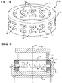
- the plurality of holes 38 may have a S-shaped configuration, as shown in Figure 7A .
- the plurality of holes 38 may have a hexagonal configuration, as shown in Figure 7B .
- the plurality of holes 38 may have a Z-shaped configuration, as shown in Figure 7C .
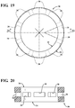
- the plurality of holes 38 converges toward a center point of the damper 20. Said differently, an area of plurality of holes 38 at the exterior surface 32 is larger than an area of the plurality of holes 38 at the interior surface 30.
- Each of the plurality of holes 38 has a length L defined between the interior surface 30 and the exterior surface 32.
- a height H and width W of each of the plurality of holes may decrease along the length L of the holes 38 moving from the exterior surface 32 toward the interior surface 30.
- the width W of the holes 38 may remain constant while only the height H decreases along the length L of the holes 38 moving from the exterior surface 32 toward the interior surface 30.
- the height H of the holes 38 may remain constant while only the width W decreases along the length L of the holes 38 moving from the exterior surface 32 toward the interior surface 30.
- the second component 24 may include a striker 40 movable with the second component 24 for compressing the damper 20 between the attachment cup 26 and the striker 40 as the second component 24 moves along the jounce axis JA toward the first component 22 for absorbing jounce between the first and second components 22, 24.
- the damper 20 is used with a steering system of the vehicle.
- the first component 22 may be a gear housing 42 and the second component 24 may be rod 44 extending from the gear housing 42 to translate rotation of a steering wheel to movement of the tires of the vehicle.
- the attachment cup 26 is coupled to the gear housing 42. It is to be appreciated that the attachment cup 26 may be an integral component of the gear houseing.
- the second component 24 has a cylindrical configuration and extends into the attachment cup 26 for compressing the damper 20 within the attachment cup 26 as the second component 24 moves along the jounce axis JA toward the first component 22.
- the second component 24 may have a step 46 such that the second component 24 has a first portion 48 having a first diameter D1 and a second portion 50 having a second diameter D2 that is smaller than the first diameter D1 of the first portion 48 to define the step 46.
- the second portion 50 of the second component 24 is disposed through the hollow interior of the damper 20 such that the damper 20 is compressed between the attachment cup 26 and the step 46 of the second component 24 as the second component 24 moves along the jounce axis JA toward the first component 22.
- the impact force when the vehicle hits an obstruction, such as the curb, the impact force is generated.
- the impact force may be a lateral force which results in the rod 44, which is the second component 24, being forced into the gear housing 42, which is the first component 22.
- the step 46 of the second component 24 contacts the damper 20 in the attachment cup 26, as shown in Figure 9 .
- the step 46 of the second component 24 then compresses the damper 20 thereby allowing the damper 20 to absorb the impact force or jounce that resulting from the vehicle hitting the object.
- the damper 20 may be used with a jounce bumper to provide a dual-rate jounce bumper assembly 52 for managing the energy generated from the impact force.
- the dual-rate jounce bumper assembly 52 absorbs energy between the first component 22 and the second component 24.
- the first component 22 is typically a frame 54 of the vehicle and the second component 24 is a strut assembly 56, which is part of a suspension system of the vehicle. It is to be appreciated that the first component 22 may alternatively be a shock mount of the suspension system.
- the dual-rate jounce bumper assembly 52 includes a bumper 58 having a first end 60 disposed within the attachment cup 26 and a second end 62 spaced from the first end 60 for contacting the second component 24 as the second component 24 moves along the jounce axis JA toward the first component 22.
- the damper 20 is disposed on the first end 60 of the bumper 58 within the attachment cup 26.
- the bumper 58 is compressed first to absorb jounce between the first and second components 22, 24. Said differently, the bumper 58 compresses first to stifle shock and protect the first and second components 22, 24.
- the damper 20 is then compressed to absorb and dampen any remaining force between the first and second components 22, 24.
- the stiffness of the damper 20, as described above is greater than a stiffness of the bumper 58 such that the bumper 58 compresses first before the damper 20 is compressed.
- the bumper 58 comprises microcellular urethane and the damper 20 comprises the thermoplastic polyurethane.
- the second component 24 may include the striker 40 aligned with the jounce axis JA such that the striker 40 contacts the bumper 58 for compressing the bumper 58 and then the damper 20.
- Figure 13 shows the dual-rate jounce bumper assembly 52 coupled to the strut assembly 56.
- the damper 20 and the bumper 58 define a height H of the dual-rate jounce bumper assembly 52.
- the strut assembly 56 includes a cylinder 64, which is the second component 24 described above, and a piston rod 66 displaceable relative to the cylinder 64 along the jounce axis JA.
- An end 68 of the piston rod 66 is coupled to the frame 54 for coupling the suspension system to the frame 54 of the vehicle.
- the dual-rate jounce bumper assembly 52 is aligned with the jounce axis JA to ensure the cylinder 64 contacts the dual-rate jounce bumper assembly 52 as the piston rod 66 collapses into the cylinder 64 to allow the dual-rate jounce bumper assembly 52 to absorb the impact force.
- the piston rod 66 extends through the dual-rate jounce bumper assembly 52.
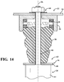
- the impact force is generated. If the impact force is greater than the suspension system can absorb, the components of the suspension system, such as the cylinder 64 of the strut assembly 56 contacts the bumper 58, as shown in Figure 14 . The cylinder 64 then compresses the bumper 58, as shown in Figure 15 . The greater the impact force, the greater the compression of the bumper 58. Once the bumper 58 is compressed to the predetermined value, the damper 20 is then compressed to absorb remaining jounce between the first and second components 22, 24, as shown in Figure 16 .
- the damper 20 may be embedded within the bumper 58.
- the bumper 58 may define a pocket 70 for receiving the damper 20. Placing the damper 20 within the pocket 70 allows dual-rate jounce bumper assembly 52 to take up a smaller area, to fit within the attachment cup 26, and conform with the geometry of the bumper 58.
- the first end 60 of the bumper 58 defines the pocket 70.
- any portion of the bumper 58 may define the pocket 70.
- the pocket 70 can be formed in the bumper 58 by any suitable method.
- the pocket 70 can be formed at the time of molding the bumper 58.
- the pocket 70 can be formed after the bumper 58 is formed by removal material for the bumper 58.
- the damper 20 may be completely embedded within the bumper 58 such that the damper 20 does not extend from the bumper 58.
- the damper 20 may be completely disposed within the pocket 70 such that the damper 20 does not extend from the bumper 58.
- the pocket 70 may completely surround the damper 20 such that the damper is not visible when the dual-rate jounce bumper assembly 52 is viewed.
- the bumper 58 may be formed with the damper 30 present such that the bumper 58 is formed around the damper 20.
- the dual-rate jounce bumper assembly 52 has been described in connection with a strut assembly 56, the dual-rate jounce bumper assembly 52 can be used with other components of the suspension system, such as shocks. It is also to be appreciated that the dual-rate jounce bumper assembly 52 may be used with components other than those of the suspension system.
Landscapes
- Engineering & Computer Science (AREA)
- General Engineering & Computer Science (AREA)
- Mechanical Engineering (AREA)
- Vibration Dampers (AREA)
- Fluid-Damping Devices (AREA)
- Steering-Linkage Mechanisms And Four-Wheel Steering (AREA)
- Vehicle Body Suspensions (AREA)
- Springs (AREA)
- Vibration Prevention Devices (AREA)
Claims (13)
- Dämpfer (20) zur Energieaufnahme zwischen einem ersten Bauteil (22) und einem zweiten Bauteil (24), wobei das zweite Bauteil (24) entlang einer Einfederungsachse (JA) zum ersten Bauteil (22) hin beabstandet und beweglich ist, wobei das Dämpferelement (20) umfasst: einen Körper (28), der eine ringförmige Ausgestaltung aufweist und eine erste Kante (34) zum Eingreifen in das erste Bauteil (22) und eine zweite Kante (36) zum Eingreifen in das zweite Bauteil (24) umfasst, wobei die zweite Kante (36) zur ersten Kante (34) beabstandet ist und der Körper (28) eine Mehrzahl von Löchern (38) definiert, die um den Körper (28) herum beabstandet sind, wobei sich jedes der Löcher (38) zu einem Mittelpunkt des Dämpfers (20) hin verjüngt, wobei die mehreren Löcher (38) dazu ausgelegt sind, dem Dämpfer (20) eine axiale Kompression zur Aufnahme von Energie zu gestatten, wenn sich das erste oder zweite Bauteil (22), (24) entlang der Einfederungsachse (JA) bewegt,
wobei der Körper (28) eine Außenfläche (32)und eine zur Außenfläche (32) beabstandete Innenfläche (30) aufweist, gekennzeichnet dadurch, dass eine Fläche der Löcher (38) an der Außenfläche (32) jeweils größer ist als eine Fläche des jeweiligen Loches an der Innenfläche (30). - Dämpfer (20) nach Anspruch 1, wobei die Innenfläche (30) einen Innenhohlraum definiert, um dem Körper (28) die ringförmige Ausgestaltung zu verleihen.
- Dämpfer (20) nach einem vorherigen Anspruch, wobei jedes der Löcher (38) eine kreisförmige Ausgestaltung aufweist.
- Dämpfer (20) nach einem der Ansprüche 1 und 2, wobei jedes der Löcher (38) eine trapezförmige Ausgestaltung aufweist.
- Dämpfer (20) nach einem der Ansprüche 1 und 2, wobei jedes der Löcher (38) eine rhombenförmige Ausgestaltung aufweist.
- Dämpfer (20) nach einem der Ansprüche 1 und 2, wobei jedes der Löcher (38) eine rechteckige Ausgestaltung aufweist.
- Dämpfer (20) nach einem vorherigen Anspruch, wobei der Körper (28) einen elastomeren Werkstoff umfasst.
- Zweiraten-Einfederungsanschlags-Anordnung (52) zur Energieaufnahme zwischen dem ersten Bauteil (22) und dem zweiten Bauteil (24) eines Fahrzeugs, wobei das zweite Bauteil (24) entlang der Einfederungsachse (JA) zum ersten Bauteil (22) hin beabstandet und beweglich ist, wobei die Zweiraten-Einfederungsanschlags-Anordnung (52) umfasst:einen Anschlagspuffer (58) mit einem ersten Ende (60), das dazu ausgelegt ist, mit dem ersten Bauteil (22) verbunden zu werden, und einem zum ersten Ende (60) beabstandeten zweiten Ende (62), das dazu ausgelegt ist, das zweite Bauteil (24) zu berühren, wenn das zweite Bauteil (24) sich entlang der Einfederungsachse (JA) zum erste Bauteil (22) hin bewegt, wobei der Anschlagspuffer (58) axial komprimierbar ist, um Energie aufzunehmen, wenn das erste oder das zweite Bauteil (22), (24) sich entlang der Einfederungsachse (JA) bewegt; undden Dämpfer (20) nach Anspruch 1, wobei der Dämpfer (20) am ersten Ende (60) des Anschlagspuffers (58) angeordnet ist, wobei der Dämpfer (20) eine Steifigkeit aufweist, die höher als eine Steifigkeit des Anschlagspuffers (58) ist, so dass der Anschlagspuffer (58) durch das zweite Glied auf einen vorherbestimmten Wert komprimierbar ist, bevor der Dämpfer (20) komprimiert wird, um Energie zwischen dem ersten und zweiten Bauteil (22), (24) aufzunehmen, undwobei der Anschlagspuffer (58) eine Aussparung zur Aufnahme des Dämpfers (20) definiert, so dass der Dämpfer (20) in den Anschlagspuffer (58) eingebettet ist.
- Zweiraten-Einfederungsanschlags-Anordnung (52) nach Anspruch 8, wobei der Anschlagspuffer (58) mikrozellulares Urethan umfasst und der Dämpfer (20) einen elastomeren Werkstoff umfasst.
- Zweiraten-Einfederungsanschlags-Anordnung (52) nach einem der Ansprüche 8 und 9, wobei der Körper (28) des Dämpfers (20) eine Innenfläche (30) umfasst, die einen Innenhohlraum definiert, um dem Körper (28) die ringförmige Ausgestaltung zu verleihen.
- Aufhängungssystem für ein Fahrzeug, umfassend:das erste Bauteil (22);das zweite Bauteil (24), das zum ersten Bauteil (22) hin entlang der Einfederungsachse (JA) beabstandet und beweglich ist; unddie Zweiraten-Einfederungsanschlags-Anordnung (52) nach Anspruch 8.
- Aufhängungssystem nach Anspruch 11, wobei der Anschlagspuffer (58) mikrozellulares Urethan umfasst und der Dämpfer (20) einen elastomeren Werkstoff umfasst.
- Dämpfer (20) nach Anspruch 1, wobei jedes der Löcher (38) eine definierte Länge zwischen der Außenfläche (32) und der Innenfläche (30) aufweist, wobei eine Höhe und/oder Breite jedes der Löcher (38) entlang der Länge der Löcher (38) von der Außenfläche (32) zur Innenfläche (30) abnimmt.
Applications Claiming Priority (3)
| Application Number | Priority Date | Filing Date | Title |
|---|---|---|---|
| US201261708738P | 2012-10-02 | 2012-10-02 | |
| US201361792595P | 2013-03-15 | 2013-03-15 | |
| PCT/US2013/062983 WO2014055599A1 (en) | 2012-10-02 | 2013-10-02 | Damper |
Publications (2)
| Publication Number | Publication Date |
|---|---|
| EP2904287A1 EP2904287A1 (de) | 2015-08-12 |
| EP2904287B1 true EP2904287B1 (de) | 2018-09-12 |
Family
ID=49356520
Family Applications (1)
| Application Number | Title | Priority Date | Filing Date |
|---|---|---|---|
| EP13776908.9A Active EP2904287B1 (de) | 2012-10-02 | 2013-10-02 | Dämpfer |
Country Status (7)
| Country | Link |
|---|---|
| US (1) | US9764612B2 (de) |
| EP (1) | EP2904287B1 (de) |
| JP (1) | JP2016500142A (de) |
| KR (1) | KR20150068414A (de) |
| CN (1) | CN104797842B (de) |
| BR (1) | BR112015007323A2 (de) |
| WO (1) | WO2014055599A1 (de) |
Families Citing this family (17)
| Publication number | Priority date | Publication date | Assignee | Title |
|---|---|---|---|---|
| DE112013004252T5 (de) * | 2012-08-31 | 2015-07-09 | Firestone Industrial Products Company, Llc | Gasfeder- und Gasdampferanordnungen und Zusammenbauverfahren |
| US9428021B2 (en) * | 2012-10-02 | 2016-08-30 | Basf Se | Jounce bumper |
| US10000102B2 (en) * | 2015-06-19 | 2018-06-19 | GM Global Technology Operations LLC | Tunable compact spring aid |
| EP3338002B1 (de) * | 2015-08-21 | 2021-01-13 | Basf Se | Elastomerfeder für fahrzeug |
| US10017026B2 (en) | 2015-11-10 | 2018-07-10 | Federal-Mogul Motorparts Llc | Sway bar linkage with bushing |
| DE102016201733A1 (de) | 2016-02-04 | 2017-08-10 | Ford Global Technologies, Llc | Stoßdämpfer-Baugruppe für ein Kraftfahrzeug |
| DE102016216009B4 (de) | 2016-08-25 | 2020-07-09 | Volkswagen Aktiengesellschaft | Pufferanordnung aus Elastomermaterial zur Anordnung zwischen einem Schwingungsdämpfer und einem Dämpferlager einer Radaufhängung eines Kraftfahrzeugs |
| US10830306B2 (en) * | 2016-12-30 | 2020-11-10 | Firestone Industrial Products Company, Llc | Jounce bumper assemblies as well as gas spring assemblies including same |
| CN109456576A (zh) * | 2017-09-06 | 2019-03-12 | 浙江台州多邦高分子材料科技有限公司 | 一种高分子减震弹簧 |
| US10718396B2 (en) * | 2018-01-26 | 2020-07-21 | Goodrich Corporation | Tunable suspension limiters for suspension arrangements |
| CN109681574B (zh) * | 2019-01-21 | 2020-12-04 | 常州信息职业技术学院 | 一种用于机动车的减震器组件及其组装方法 |
| EP3969778B1 (de) * | 2019-05-13 | 2023-03-29 | BASF Polyurethanes GmbH | Federelement, insbesondere anschlagpuffer, für einen fahrzeugstossdämpfer |
| WO2020245217A1 (en) * | 2019-06-03 | 2020-12-10 | Basf Polyurethanes Gmbh | Spring element, in particular jounce bumper, for a vehicle suspension |
| WO2021058614A1 (en) * | 2019-09-26 | 2021-04-01 | Basf Se | A dual rate jounce bumper and a vehicle comprising the same |
| CN111169663B (zh) * | 2020-01-17 | 2021-09-14 | 北京时代精衡航天科技有限公司 | 深空探测撞击过载测试及数据无线传输测量装置 |
| CN119032017A (zh) * | 2022-04-12 | 2024-11-26 | 巴斯夫欧洲公司 | 负载管理撞针帽 |
| US12533919B2 (en) * | 2023-03-15 | 2026-01-27 | GM Global Technology Operations LLC | Jounce bumper |
Family Cites Families (42)
| Publication number | Priority date | Publication date | Assignee | Title |
|---|---|---|---|---|
| US2888258A (en) * | 1956-05-11 | 1959-05-26 | Hoffstrom Bo Nilsson | Springs |
| FR1229796A (fr) * | 1959-03-04 | 1960-09-09 | Renault | Ressort en caoutchouc |
| DE1475137B2 (de) * | 1965-05-15 | 1971-02-25 | Rix, Johannes Dipl Ing , 3500 Kassel | Hohlfelder insbesondere zum auffangen von stoessen bei fahrzeugen |
| US3606295A (en) * | 1968-11-12 | 1971-09-20 | Unilan Ag | Shock absorber |
| US4191398A (en) * | 1976-07-19 | 1980-03-04 | Willetts Elwood H | Vehicle suspension system |
| BE859468A (nl) * | 1977-10-07 | 1978-04-07 | Poppe Willy | Schuimveer |
| IT1156346B (it) | 1982-11-29 | 1987-02-04 | Pirelli | Dispositivo ammortizzatore |
| JPS6177505A (ja) | 1984-09-26 | 1986-04-21 | Kinugawa Rubber Ind Co Ltd | リバウンドバンパ |
| US4858897A (en) | 1987-11-16 | 1989-08-22 | Hideki Irifune | Spring |
| DE8717817U1 (de) * | 1987-11-23 | 1990-04-26 | Woco Franz-Josef Wolf & Co, 63628 Bad Soden-Salmünster | Federelement |
| US5409199A (en) * | 1990-05-07 | 1995-04-25 | Kahmann; Manfred | Shock absorbing fender |
| US5467970A (en) * | 1994-06-06 | 1995-11-21 | General Motors Corporation | Vehicle suspension system with jounce bumper |
| US5467971A (en) * | 1994-08-08 | 1995-11-21 | General Motors Corporation | Strut assembly with integral bearing and spring seat |
| US5632504A (en) * | 1994-11-21 | 1997-05-27 | Gallagher; Daniel M. | Trailer spring |
| US6251493B1 (en) * | 1996-04-08 | 2001-06-26 | 3M Innovative Properties Company | Vibration and shock attenuating articles and method of attenuating vibrations and shocks therewith |
| DE19722795A1 (de) * | 1997-05-30 | 1998-12-03 | Hilti Ag | Setzgerät |
| JP3731359B2 (ja) * | 1998-11-24 | 2006-01-05 | 東海ゴム工業株式会社 | バンパスプリング |
| US6254072B1 (en) | 1999-03-31 | 2001-07-03 | Daimlerchrysler Corporation | Spring isolator and jounce bumper for a motor vehicle suspension |
| DE10105791A1 (de) * | 2001-02-07 | 2002-08-08 | Basf Ag | Federelement |
| US20050073166A1 (en) * | 2003-10-03 | 2005-04-07 | Ford Global Technologies, Llc | Hybrid material body mount for automotive vehicles |
| US20050230891A1 (en) * | 2004-04-14 | 2005-10-20 | Griffin Gary J | Jounce bumper |
| DE102004019991B4 (de) * | 2004-04-23 | 2015-09-24 | Volkswagen Ag | Radaufhängung |
| US7070157B2 (en) * | 2004-06-17 | 2006-07-04 | Basf Corporation | Mount assembly |
| US20060001205A1 (en) * | 2004-06-30 | 2006-01-05 | Irfan Raza | Jounce bumper |
| US20060043659A1 (en) * | 2004-08-30 | 2006-03-02 | Marian Gofron | Dual spring jounce bumper assembly |
| CN2748698Y (zh) * | 2004-11-17 | 2005-12-28 | 北京特特舒汽车缓冲器科技有限公司 | 汽车高压线圈用缓冲器 |
| JP4362439B2 (ja) | 2004-12-17 | 2009-11-11 | 東海ゴム工業株式会社 | サスペンション装置用のバウンドストッパ |
| DE102005030528A1 (de) | 2005-06-30 | 2007-01-11 | Carl Freudenberg Kg | Federkörper |
| US20080012188A1 (en) * | 2006-07-17 | 2008-01-17 | Dickson Daniel G | One-piece microcellular polyurethane insulator having different densities |
| WO2008137029A2 (en) | 2007-05-01 | 2008-11-13 | E. I. Du Pont De Nemours And Company | Jounce bumpers made by corrugated extrusio |
| KR100916796B1 (ko) * | 2008-05-23 | 2009-09-14 | 현대자동차주식회사 | 현가장치용 범프 스토퍼 |
| US8123203B2 (en) * | 2009-02-25 | 2012-02-28 | GM Global Technology Operations LLC | Vehicular jounce bumper assembly |
| US20100230877A1 (en) * | 2009-03-13 | 2010-09-16 | Gm Global Technology Operations, Inc. | Vehicular impact bumper assembly |
| US8353501B2 (en) * | 2009-04-24 | 2013-01-15 | Willy Poppe | Foam spring for pillows, cushions, mattresses or the like and a method for manufacturing such a foam spring |
| WO2011072005A2 (en) * | 2009-12-08 | 2011-06-16 | Trelleborg Ysh, Inc. | Micro cellular urethane (mcu) progressive rate bump stop/spring aid |
| US8657271B2 (en) | 2010-08-12 | 2014-02-25 | E I Du Pont De Nemours And Company | Thermoplastic jounce bumpers |
| US20120193852A1 (en) | 2011-01-28 | 2012-08-02 | Basf Se | Damper bearing with profiled insert |
| US20130119593A1 (en) | 2011-02-10 | 2013-05-16 | Nok Corporation | Rebound stopper |
| JP2012167704A (ja) | 2011-02-10 | 2012-09-06 | Nok Corp | リバウンドストッパ |
| WO2013113042A1 (en) * | 2012-01-29 | 2013-08-01 | Firestone Industrial Products Company, Llc | Jounce bumper, end member, gas spring assembly and method of assembly |
| US8720921B1 (en) * | 2012-10-30 | 2014-05-13 | SuperSprings International, Inc. | Vehicular suspension enhancement |
| US9186948B2 (en) * | 2013-12-06 | 2015-11-17 | GM Global Technology Operations LLC | Systems and methods for damper having an insert |
-
2013
- 2013-10-02 JP JP2015535754A patent/JP2016500142A/ja not_active Ceased
- 2013-10-02 WO PCT/US2013/062983 patent/WO2014055599A1/en not_active Ceased
- 2013-10-02 CN CN201380058909.6A patent/CN104797842B/zh active Active
- 2013-10-02 BR BR112015007323A patent/BR112015007323A2/pt not_active Application Discontinuation
- 2013-10-02 EP EP13776908.9A patent/EP2904287B1/de active Active
- 2013-10-02 KR KR1020157011036A patent/KR20150068414A/ko not_active Ceased
- 2013-10-02 US US14/433,290 patent/US9764612B2/en active Active
Non-Patent Citations (1)
| Title |
|---|
| None * |
Also Published As
| Publication number | Publication date |
|---|---|
| EP2904287A1 (de) | 2015-08-12 |
| WO2014055599A1 (en) | 2014-04-10 |
| CN104797842A (zh) | 2015-07-22 |
| BR112015007323A2 (pt) | 2017-07-04 |
| JP2016500142A (ja) | 2016-01-07 |
| CN104797842B (zh) | 2017-11-10 |
| KR20150068414A (ko) | 2015-06-19 |
| US20150239315A1 (en) | 2015-08-27 |
| US9764612B2 (en) | 2017-09-19 |
Similar Documents
| Publication | Publication Date | Title |
|---|---|---|
| EP2904287B1 (de) | Dämpfer | |
| US9545829B2 (en) | Dual-rate jounce bumper | |
| EP3338002B1 (de) | Elastomerfeder für fahrzeug | |
| EP2903839B1 (de) | Einfederungsanschlaganordnung | |
| US7281705B2 (en) | Jounce assembly for a suspension system | |
| US10274036B2 (en) | Energy management jounce bumper assembly | |
| EP2938506B1 (de) | Anschlagdämpfer | |
| US20050230891A1 (en) | Jounce bumper | |
| US12163568B2 (en) | Cover cap and insulator for shock absorber including the same | |
| EP3517802B1 (de) | Abstimmbare aufhängungsbegrenzer für aufhängungsanordnungen | |
| KR101176569B1 (ko) | 소음 감소용 완충장치를 가지는 쇽업소버 | |
| KR20080086166A (ko) | 쇽업소버의 범퍼 러버 | |
| KR100589189B1 (ko) | 현가 장치의 범퍼 스토퍼 구조 | |
| MXPA06005234A (es) | Montaje de soporte de muelle |
Legal Events
| Date | Code | Title | Description |
|---|---|---|---|
| PUAI | Public reference made under article 153(3) epc to a published international application that has entered the european phase |
Free format text: ORIGINAL CODE: 0009012 |
|
| 17P | Request for examination filed |
Effective date: 20150504 |
|
| AK | Designated contracting states |
Kind code of ref document: A1 Designated state(s): AL AT BE BG CH CY CZ DE DK EE ES FI FR GB GR HR HU IE IS IT LI LT LU LV MC MK MT NL NO PL PT RO RS SE SI SK SM TR |
|
| AX | Request for extension of the european patent |
Extension state: BA ME |
|
| DAX | Request for extension of the european patent (deleted) | ||
| 17Q | First examination report despatched |
Effective date: 20170711 |
|
| GRAP | Despatch of communication of intention to grant a patent |
Free format text: ORIGINAL CODE: EPIDOSNIGR1 |
|
| INTG | Intention to grant announced |
Effective date: 20180409 |
|
| GRAS | Grant fee paid |
Free format text: ORIGINAL CODE: EPIDOSNIGR3 |
|
| GRAA | (expected) grant |
Free format text: ORIGINAL CODE: 0009210 |
|
| AK | Designated contracting states |
Kind code of ref document: B1 Designated state(s): AL AT BE BG CH CY CZ DE DK EE ES FI FR GB GR HR HU IE IS IT LI LT LU LV MC MK MT NL NO PL PT RO RS SE SI SK SM TR |
|
| REG | Reference to a national code |
Ref country code: GB Ref legal event code: FG4D |
|
| REG | Reference to a national code |
Ref country code: CH Ref legal event code: EP |
|
| REG | Reference to a national code |
Ref country code: IE Ref legal event code: FG4D |
|
| REG | Reference to a national code |
Ref country code: DE Ref legal event code: R096 Ref document number: 602013043580 Country of ref document: DE |
|
| REG | Reference to a national code |
Ref country code: AT Ref legal event code: REF Ref document number: 1040970 Country of ref document: AT Kind code of ref document: T Effective date: 20181015 |
|
| REG | Reference to a national code |
Ref country code: FR Ref legal event code: PLFP Year of fee payment: 6 |
|
| REG | Reference to a national code |
Ref country code: NL Ref legal event code: MP Effective date: 20180912 |
|
| REG | Reference to a national code |
Ref country code: LT Ref legal event code: MG4D |
|
| PG25 | Lapsed in a contracting state [announced via postgrant information from national office to epo] |
Ref country code: LT Free format text: LAPSE BECAUSE OF FAILURE TO SUBMIT A TRANSLATION OF THE DESCRIPTION OR TO PAY THE FEE WITHIN THE PRESCRIBED TIME-LIMIT Effective date: 20180912 Ref country code: SE Free format text: LAPSE BECAUSE OF FAILURE TO SUBMIT A TRANSLATION OF THE DESCRIPTION OR TO PAY THE FEE WITHIN THE PRESCRIBED TIME-LIMIT Effective date: 20180912 Ref country code: BG Free format text: LAPSE BECAUSE OF FAILURE TO SUBMIT A TRANSLATION OF THE DESCRIPTION OR TO PAY THE FEE WITHIN THE PRESCRIBED TIME-LIMIT Effective date: 20181212 Ref country code: NO Free format text: LAPSE BECAUSE OF FAILURE TO SUBMIT A TRANSLATION OF THE DESCRIPTION OR TO PAY THE FEE WITHIN THE PRESCRIBED TIME-LIMIT Effective date: 20181212 Ref country code: FI Free format text: LAPSE BECAUSE OF FAILURE TO SUBMIT A TRANSLATION OF THE DESCRIPTION OR TO PAY THE FEE WITHIN THE PRESCRIBED TIME-LIMIT Effective date: 20180912 Ref country code: RS Free format text: LAPSE BECAUSE OF FAILURE TO SUBMIT A TRANSLATION OF THE DESCRIPTION OR TO PAY THE FEE WITHIN THE PRESCRIBED TIME-LIMIT Effective date: 20180912 Ref country code: GR Free format text: LAPSE BECAUSE OF FAILURE TO SUBMIT A TRANSLATION OF THE DESCRIPTION OR TO PAY THE FEE WITHIN THE PRESCRIBED TIME-LIMIT Effective date: 20181213 |
|
| PG25 | Lapsed in a contracting state [announced via postgrant information from national office to epo] |
Ref country code: HR Free format text: LAPSE BECAUSE OF FAILURE TO SUBMIT A TRANSLATION OF THE DESCRIPTION OR TO PAY THE FEE WITHIN THE PRESCRIBED TIME-LIMIT Effective date: 20180912 Ref country code: LV Free format text: LAPSE BECAUSE OF FAILURE TO SUBMIT A TRANSLATION OF THE DESCRIPTION OR TO PAY THE FEE WITHIN THE PRESCRIBED TIME-LIMIT Effective date: 20180912 Ref country code: AL Free format text: LAPSE BECAUSE OF FAILURE TO SUBMIT A TRANSLATION OF THE DESCRIPTION OR TO PAY THE FEE WITHIN THE PRESCRIBED TIME-LIMIT Effective date: 20180912 |
|
| PGFP | Annual fee paid to national office [announced via postgrant information from national office to epo] |
Ref country code: FR Payment date: 20181025 Year of fee payment: 6 |
|
| REG | Reference to a national code |
Ref country code: AT Ref legal event code: MK05 Ref document number: 1040970 Country of ref document: AT Kind code of ref document: T Effective date: 20180912 |
|
| PG25 | Lapsed in a contracting state [announced via postgrant information from national office to epo] |
Ref country code: CZ Free format text: LAPSE BECAUSE OF FAILURE TO SUBMIT A TRANSLATION OF THE DESCRIPTION OR TO PAY THE FEE WITHIN THE PRESCRIBED TIME-LIMIT Effective date: 20180912 Ref country code: RO Free format text: LAPSE BECAUSE OF FAILURE TO SUBMIT A TRANSLATION OF THE DESCRIPTION OR TO PAY THE FEE WITHIN THE PRESCRIBED TIME-LIMIT Effective date: 20180912 Ref country code: EE Free format text: LAPSE BECAUSE OF FAILURE TO SUBMIT A TRANSLATION OF THE DESCRIPTION OR TO PAY THE FEE WITHIN THE PRESCRIBED TIME-LIMIT Effective date: 20180912 Ref country code: IT Free format text: LAPSE BECAUSE OF FAILURE TO SUBMIT A TRANSLATION OF THE DESCRIPTION OR TO PAY THE FEE WITHIN THE PRESCRIBED TIME-LIMIT Effective date: 20180912 Ref country code: AT Free format text: LAPSE BECAUSE OF FAILURE TO SUBMIT A TRANSLATION OF THE DESCRIPTION OR TO PAY THE FEE WITHIN THE PRESCRIBED TIME-LIMIT Effective date: 20180912 Ref country code: NL Free format text: LAPSE BECAUSE OF FAILURE TO SUBMIT A TRANSLATION OF THE DESCRIPTION OR TO PAY THE FEE WITHIN THE PRESCRIBED TIME-LIMIT Effective date: 20180912 Ref country code: ES Free format text: LAPSE BECAUSE OF FAILURE TO SUBMIT A TRANSLATION OF THE DESCRIPTION OR TO PAY THE FEE WITHIN THE PRESCRIBED TIME-LIMIT Effective date: 20180912 Ref country code: IS Free format text: LAPSE BECAUSE OF FAILURE TO SUBMIT A TRANSLATION OF THE DESCRIPTION OR TO PAY THE FEE WITHIN THE PRESCRIBED TIME-LIMIT Effective date: 20190112 Ref country code: PL Free format text: LAPSE BECAUSE OF FAILURE TO SUBMIT A TRANSLATION OF THE DESCRIPTION OR TO PAY THE FEE WITHIN THE PRESCRIBED TIME-LIMIT Effective date: 20180912 |
|
| PG25 | Lapsed in a contracting state [announced via postgrant information from national office to epo] |
Ref country code: PT Free format text: LAPSE BECAUSE OF FAILURE TO SUBMIT A TRANSLATION OF THE DESCRIPTION OR TO PAY THE FEE WITHIN THE PRESCRIBED TIME-LIMIT Effective date: 20190112 Ref country code: SK Free format text: LAPSE BECAUSE OF FAILURE TO SUBMIT A TRANSLATION OF THE DESCRIPTION OR TO PAY THE FEE WITHIN THE PRESCRIBED TIME-LIMIT Effective date: 20180912 Ref country code: SM Free format text: LAPSE BECAUSE OF FAILURE TO SUBMIT A TRANSLATION OF THE DESCRIPTION OR TO PAY THE FEE WITHIN THE PRESCRIBED TIME-LIMIT Effective date: 20180912 |
|
| REG | Reference to a national code |
Ref country code: CH Ref legal event code: PL |
|
| REG | Reference to a national code |
Ref country code: DE Ref legal event code: R097 Ref document number: 602013043580 Country of ref document: DE |
|
| REG | Reference to a national code |
Ref country code: BE Ref legal event code: MM Effective date: 20181031 |
|
| PG25 | Lapsed in a contracting state [announced via postgrant information from national office to epo] |
Ref country code: LU Free format text: LAPSE BECAUSE OF NON-PAYMENT OF DUE FEES Effective date: 20181002 |
|
| PLBE | No opposition filed within time limit |
Free format text: ORIGINAL CODE: 0009261 |
|
| STAA | Information on the status of an ep patent application or granted ep patent |
Free format text: STATUS: NO OPPOSITION FILED WITHIN TIME LIMIT |
|
| REG | Reference to a national code |
Ref country code: IE Ref legal event code: MM4A |
|
| PG25 | Lapsed in a contracting state [announced via postgrant information from national office to epo] |
Ref country code: MC Free format text: LAPSE BECAUSE OF FAILURE TO SUBMIT A TRANSLATION OF THE DESCRIPTION OR TO PAY THE FEE WITHIN THE PRESCRIBED TIME-LIMIT Effective date: 20180912 Ref country code: DK Free format text: LAPSE BECAUSE OF FAILURE TO SUBMIT A TRANSLATION OF THE DESCRIPTION OR TO PAY THE FEE WITHIN THE PRESCRIBED TIME-LIMIT Effective date: 20180912 |
|
| 26N | No opposition filed |
Effective date: 20190613 |
|
| GBPC | Gb: european patent ceased through non-payment of renewal fee |
Effective date: 20181212 |
|
| PG25 | Lapsed in a contracting state [announced via postgrant information from national office to epo] |
Ref country code: CH Free format text: LAPSE BECAUSE OF NON-PAYMENT OF DUE FEES Effective date: 20181031 Ref country code: BE Free format text: LAPSE BECAUSE OF NON-PAYMENT OF DUE FEES Effective date: 20181031 Ref country code: SI Free format text: LAPSE BECAUSE OF FAILURE TO SUBMIT A TRANSLATION OF THE DESCRIPTION OR TO PAY THE FEE WITHIN THE PRESCRIBED TIME-LIMIT Effective date: 20180912 Ref country code: LI Free format text: LAPSE BECAUSE OF NON-PAYMENT OF DUE FEES Effective date: 20181031 |
|
| PG25 | Lapsed in a contracting state [announced via postgrant information from national office to epo] |
Ref country code: IE Free format text: LAPSE BECAUSE OF NON-PAYMENT OF DUE FEES Effective date: 20181002 |
|
| PG25 | Lapsed in a contracting state [announced via postgrant information from national office to epo] |
Ref country code: GB Free format text: LAPSE BECAUSE OF NON-PAYMENT OF DUE FEES Effective date: 20181212 |
|
| PG25 | Lapsed in a contracting state [announced via postgrant information from national office to epo] |
Ref country code: MT Free format text: LAPSE BECAUSE OF NON-PAYMENT OF DUE FEES Effective date: 20181002 |
|
| PG25 | Lapsed in a contracting state [announced via postgrant information from national office to epo] |
Ref country code: TR Free format text: LAPSE BECAUSE OF FAILURE TO SUBMIT A TRANSLATION OF THE DESCRIPTION OR TO PAY THE FEE WITHIN THE PRESCRIBED TIME-LIMIT Effective date: 20180912 |
|
| PG25 | Lapsed in a contracting state [announced via postgrant information from national office to epo] |
Ref country code: MK Free format text: LAPSE BECAUSE OF NON-PAYMENT OF DUE FEES Effective date: 20180912 Ref country code: HU Free format text: LAPSE BECAUSE OF FAILURE TO SUBMIT A TRANSLATION OF THE DESCRIPTION OR TO PAY THE FEE WITHIN THE PRESCRIBED TIME-LIMIT; INVALID AB INITIO Effective date: 20131002 Ref country code: CY Free format text: LAPSE BECAUSE OF FAILURE TO SUBMIT A TRANSLATION OF THE DESCRIPTION OR TO PAY THE FEE WITHIN THE PRESCRIBED TIME-LIMIT Effective date: 20180912 |
|
| PG25 | Lapsed in a contracting state [announced via postgrant information from national office to epo] |
Ref country code: FR Free format text: LAPSE BECAUSE OF NON-PAYMENT OF DUE FEES Effective date: 20191031 |
|
| PGFP | Annual fee paid to national office [announced via postgrant information from national office to epo] |
Ref country code: DE Payment date: 20251028 Year of fee payment: 13 |