EP2904349B1 - Procédé d'étalonnage d'un appareil photo - Google Patents
Procédé d'étalonnage d'un appareil photo Download PDFInfo
- Publication number
- EP2904349B1 EP2904349B1 EP13843369.3A EP13843369A EP2904349B1 EP 2904349 B1 EP2904349 B1 EP 2904349B1 EP 13843369 A EP13843369 A EP 13843369A EP 2904349 B1 EP2904349 B1 EP 2904349B1
- Authority
- EP
- European Patent Office
- Prior art keywords
- camera device
- image
- length
- calibration
- plane
- Prior art date
- Legal status (The legal status is an assumption and is not a legal conclusion. Google has not performed a legal analysis and makes no representation as to the accuracy of the status listed.)
- Active
Links
- 238000000034 method Methods 0.000 title claims description 16
- 238000005259 measurement Methods 0.000 description 17
- 230000003287 optical effect Effects 0.000 description 13
- 238000010586 diagram Methods 0.000 description 7
- 230000036541 health Effects 0.000 description 4
- 230000004075 alteration Effects 0.000 description 3
- 238000003384 imaging method Methods 0.000 description 2
- 238000004519 manufacturing process Methods 0.000 description 2
- 230000008569 process Effects 0.000 description 2
- 241000226585 Antennaria plantaginifolia Species 0.000 description 1
- 229910000831 Steel Inorganic materials 0.000 description 1
- 230000003187 abdominal effect Effects 0.000 description 1
- 230000003190 augmentative effect Effects 0.000 description 1
- 230000008901 benefit Effects 0.000 description 1
- 238000004364 calculation method Methods 0.000 description 1
- 230000008859 change Effects 0.000 description 1
- 230000003247 decreasing effect Effects 0.000 description 1
- 238000001514 detection method Methods 0.000 description 1
- 201000010099 disease Diseases 0.000 description 1
- 208000037265 diseases, disorders, signs and symptoms Diseases 0.000 description 1
- 238000010191 image analysis Methods 0.000 description 1
- 230000010354 integration Effects 0.000 description 1
- 229910052751 metal Inorganic materials 0.000 description 1
- 239000002184 metal Substances 0.000 description 1
- 150000002739 metals Chemical class 0.000 description 1
- 238000012805 post-processing Methods 0.000 description 1
- 238000012545 processing Methods 0.000 description 1
- 230000003068 static effect Effects 0.000 description 1
- 239000010959 steel Substances 0.000 description 1
- 210000002784 stomach Anatomy 0.000 description 1
- 230000001131 transforming effect Effects 0.000 description 1
- 230000000007 visual effect Effects 0.000 description 1
Images


Classifications
-
- H—ELECTRICITY
- H04—ELECTRIC COMMUNICATION TECHNIQUE
- H04N—PICTORIAL COMMUNICATION, e.g. TELEVISION
- H04N17/00—Diagnosis, testing or measuring for television systems or their details
- H04N17/002—Diagnosis, testing or measuring for television systems or their details for television cameras
-
- G—PHYSICS
- G01—MEASURING; TESTING
- G01B—MEASURING LENGTH, THICKNESS OR SIMILAR LINEAR DIMENSIONS; MEASURING ANGLES; MEASURING AREAS; MEASURING IRREGULARITIES OF SURFACES OR CONTOURS
- G01B11/00—Measuring arrangements characterised by the use of optical techniques
- G01B11/02—Measuring arrangements characterised by the use of optical techniques for measuring length, width or thickness
-
- G—PHYSICS
- G01—MEASURING; TESTING
- G01B—MEASURING LENGTH, THICKNESS OR SIMILAR LINEAR DIMENSIONS; MEASURING ANGLES; MEASURING AREAS; MEASURING IRREGULARITIES OF SURFACES OR CONTOURS
- G01B21/00—Measuring arrangements or details thereof, where the measuring technique is not covered by the other groups of this subclass, unspecified or not relevant
- G01B21/02—Measuring arrangements or details thereof, where the measuring technique is not covered by the other groups of this subclass, unspecified or not relevant for measuring length, width, or thickness
- G01B21/04—Measuring arrangements or details thereof, where the measuring technique is not covered by the other groups of this subclass, unspecified or not relevant for measuring length, width, or thickness by measuring coordinates of points
- G01B21/042—Calibration or calibration artifacts
-
- G—PHYSICS
- G01—MEASURING; TESTING
- G01C—MEASURING DISTANCES, LEVELS OR BEARINGS; SURVEYING; NAVIGATION; GYROSCOPIC INSTRUMENTS; PHOTOGRAMMETRY OR VIDEOGRAMMETRY
- G01C11/00—Photogrammetry or videogrammetry, e.g. stereogrammetry; Photographic surveying
-
- G—PHYSICS
- G01—MEASURING; TESTING
- G01C—MEASURING DISTANCES, LEVELS OR BEARINGS; SURVEYING; NAVIGATION; GYROSCOPIC INSTRUMENTS; PHOTOGRAMMETRY OR VIDEOGRAMMETRY
- G01C25/00—Manufacturing, calibrating, cleaning, or repairing instruments or devices referred to in the other groups of this subclass
Definitions
- This invention relates to a method of performing an absolute length calibration according to claim 1 and to a camera device for performing an absolute length calibration according to claim 3.
- the principle of an optical system is that a Field of View, typically 40° to 50°, is projected on to the image plane where the image is produced.
- the Field of View will vary with the focal length of the system, such as when using an optical zoom, and can be recorded by image capturing software or meta data.
- Digital zoom will in the same way, decrease the Field of View, and can be recorded by image capturing software.
- a cone of light is projected onto the image sensor element.
- L the actual length of the object
- N the number of pixels
- a flower can be photographed close to the camera device and fill the whole field of view.
- a tree farther away can fill up the same field of view.
- These two objects can have the same pixel counts, but obviously have different real dimensions. This calls for some kind of calibration of the captured area in case somebody should need to perform a true scale measurement of a part or parts of the captured area.
- the invention is intended to be used on a distortion free image, or in parts of an image where the distortion can be said to be constant or known, either by design or by factory pre-calibration or other post processing of the image.
- a common image analysis task is to separate the foreground from the background and obtain the silhouette cone of the object of interest. This cone is still an angle of the 3D world and the same object closer to the camera device will have a larger pixel count than the same object farther away. There is therefore a need of making pixel size calibrations for each image taken as the distance to the object can and will vary.
- each plane parallel to the viewing plane in the scenery will give a perspective caused by its distance. It is also know to the art that the angle of a plane in relation to the viewing plane will project on the viewing plane according to cosine of the angle. Both the perspective and projection can be calibrated for any imaging system, by the distances and the angles between a calibrated viewing plane and an object surface or plane.
- 3D scanners known to the art can make real measurements of humans and other 3D objects. They are made of calibrated laser sensors measuring the distance at every point to the object, or calibrated imaging set-ups with multiple views where the cones can be overlapped and a 3D map created. But all these presented systems are either large or not easily operated by the user.
- the mirror can be assumed to be hanging on the wall, and the user can be assumed to be standing upright. Instructing the user how to stand and/or statistical or empirical studies can determine the distance between the camera device and the user.
- the Cartesian coordinate systems for the mirror and the user can be transformed, by shift and rotation, so that origo becomes the camera device with z direction along the optical axis.
- An object on the user can be transformed onto this coordinate system, by registering the calibration of the camera device viewing plane, the distance to the camera device viewing plane and the angle between the mirror and the camera device, together with the known data from above.
- the relation between the object plane and the camera device viewing plane in this coordinate system calculates a perspective and projection factor for each point in the captured image.
- the object can be calibrated by solely knowing: the perpendicular signed distance to the point on the object, d ob-ject point - d calibration plane , from the calibration viewing plane, the distance to the calibration viewing plane d calibration plane , and a calibration for the known viewing plane.
- the length of a line between two points on the object surface or object plane is the integration of each calibrated point along the line.
- Images can have some relevance without being able to calculate the absolute length dimensions of the objects of interest. Sometimes it can be of interest to look at relations in the image and by this, calculating ratios.
- the images need to be distortion free and the object needs to be positioned relative to the camera device so that angular and perspective distortion is within acceptable level for the usage.
- Two images taken at different times can be compared, by superimposing the same object over each other. The percentage difference in areas of interest can be calculated.
- absolute length measurements can be made by one single monocular camera device using the device itself, e.g. length or width of the camera device, or specific characteristics of the camera device, e.g. lens diameter, lens to edge length, length or width of digital screen, a specific pattern of the camera device, or a digital calibration image or object known by the camera device, e.g. a chess pattern or a ruler pattern on a front facing screen, or a remote device that is known and paired by the camera device.
- the camera device itself, parts of the camera device, or digital calibration screen can be seen in the image itself by taking the image in e.g. a mirror or in another reflecting surfaces e.g. polished metals such as a polished steel surface, which all function as a mirror and reflects the image back.
- the distance to the camera device viewing plane can be seamlessly calibrated by the above calibration and the Field of View of the camera device itself, when taking the image in a mirror.
- the angular calibration between a camera device and a mirror, in which the camera device takes an image of itself can be seamlessly determined by the location of the camera device reflection in the captured image.
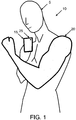
- Fig. 1 illustrates an absolute length calibration of a part of an image, for measuring an object e.g. the arm.
- the absolute length calibration of the object in the image can be done by the user taking an image of herself or himself 5 or another object in a mirror 10.
- the metadata 110 (see explanation in connection with Fig. 2 ) of the digital image 105 or the software where the image was captured with will give information about the model 170 of the camera device in use 15, e.g. smartphone model, compact camera model, or SLR camera model.
- the in situ software or post processing software will use this information to look up 120 dimensions of the camera device model 170 (see explanation in connection with Fig. 2 ) e.g.
- lens diameter, lens to edge length, length or width of the camera device screen dimensions, or a specific pattern and/or features or characteristics on the device 25.
- the dimensions will be divided by the pixel count 205 (see explanation in connection with Fig. 2 ) of the camera device 15 or its characteristic 25.
- the object 150 e.g. the arm length of the user 20 , will be measured by counting the pixels 200 (see explanation in connection with Fig. 2 ) and use the calibration 300 as explained in connection with Fig. 2 .
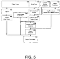
- Fig. 2 illustrates a block diagram of image software that can be used for measuring the absolute length for a part of an image.
- the digital image metadata 110 or the software where the image was captured with will give information of the camera device in use 170, e.g. smartphone model, compact camera model, or SLR camera model.
- the in situ software or post processing software will use the information about the camera device model 170 to look up dimensions 215, e.g. length or width, of the camera device model 170 and/or features or characteristics on the camera device model 170 from a local or web based database or a look up table 120.
- the software will find the image of the camera device 155 in the image 105 and read the pixel count of the dimensions and/or features or characteristics 205.
- a length to pixel calibration 300 will be made seamlessly of the user from the above data.
- the image of the object 150 e.g. the arm length of the user 20, will be measured by counting the pixels 200 and use the above calibration 300 to calculate the absolute length dimensions of the object 360.
- the method performs an absolute length calibration for an image of an object 150, the object 20, e.g. an arm in Fig. 1 is located with the camera device 15 in a mirror 10.
- the object 20, the arm could as well be covered or partly covered by the camera device in the mirror 10.
- the software carrying out the method determines at least one of the camera device dimensions 215.
- the dimensions of the camera device are based on the type or kind of the camera device 170 and reflect the real physical dimensions of the camera device.
- the dimensions of the camera device could be the dimensions of the outer contour of the device, for instance the length or the width of the iPhone in the mirror 10.
- the method captures an image 105 of the camera device 155 with an image of the object 150, e.g. the arm 20 with the camera device 15. Thereafter the method measures an image length of the object 200, e.g. the size of the arm, and further measures at least one dimension of the image of the camera device 205 from the captured image 105.
- the camera device's software measures the size of the arm 200 as well as the length of the camera device 205 or the width of the camera device 205, or both.
- the method also can be incorporated into a camera device, to manufacture a camera device for performing an absolute length calibration.
- Horizontal and lateral lines will have the same calibration in a well-designed optical system with squared image sensor elements. It is therefore sufficient to measure one dimension to calibrate the image.
- One extra orthogonal dimension can be used to increase the accuracy but will be needed if the calibration differs in the horizontal and lateral direction.
- the example above has used a part of the users body as the object for which to find the calibration for the absolute length.
- This object do not need to be a part of the user but can be any object that the user is showing in the image and is being define by the user or by software.
- the software for analyzing the image could use methods of silhouetting known in the art, which can give a sub-pixel resolution. Further accuracy can use the information of typical image distortion for the known camera device model 170. Perimeters can be calculated by use of statistical correlation to one or more widths of the body part of interest, e.g. biceps, extracted from one or multiple images from different views.
- the width and height of the camera device 15 may be replaced by lens diameter of the camera device 25, or one or more lens to edge lengths of the camera device, diagonal length of the camera device, screen dimensions, or a specific pattern of the camera device, e.g. a logo or other visible parts on the same side of the camera device 25, e.g. distances between physical buttons on the camera device 15.
- Fig. 3 illustrates how a digital calibration patter is used for absolute length calibrate of a part of an image.
- the user 5 will show the screen of the camera device 15 in the image, e.g. if the camera device and screen are on the same side of the device and an image is taken in a mirror 10.
- the calibration pattern 30 or the calibration object 30 on the camera device 15, and is known by the image capturing software is used as calibration in the same way as other camera device feature mentioned above.
- the object e.g. the arm 20 of the user 5 , will be measured by measuring the length per pixel calibration 300 and use the above calibration.
- the digital calibration image contains patterns that can be understood by the image software, e.g. ruler with marks or symbols per inch or cm 30 , or standardized color-codes on calibration pattern 30 commonly known or easily looked up in tables by software.
- the absolute length calibration can be done automatically by post processing software not using the image metadata 110 but only image recognition. The calibration proceeds in the same way as other camera device characteristics 25 mentioned above.
- the dimension of the image does not have to be the smallest known picture length, pixel, but can be a length in inches or millimeters, if the physical dimension of the image sensor is considered or if an image taken or reproduced analog. Then the above mention embodiment of e.g. a ruler on the digital screen 30 will have a certain length on the image or image plane, in fraction of inches or millimeters, and an absolute real length stated by the ruler 30 , in inches or centimeters.
- Fig. 4 illustrates one embodiment of the invention how absolute length calibration can be calculated for perspective.
- the embodiment of the invention can calibrate the distance to the camera device 15, the distance to the object 20, or the distance to the object 20 plane, and use the distances to the camera device 15 and the object 20 to calibrate the perspective by, in the rectilinear case, multiplying the distance to the object plane and dividing by the distance to the camera device calibrated viewing plane.
- This distance 40 between the camera device 15 and the object 20, can be assumed to be known, either by instructing the user 5 how to pose, or by empirical or statistical measurements on how users position the camera device 15 in relation to their body part 20.
- the camera device model 170 is looked up in a table or database 120 to find the Field of View 220.
- Metadata 110 or the image capturing software can further register the optical zoom and other features that might change the focal length and therefore the Field of View 220.
- the distance to length per pixel calibration 300 is linear for a static Field of View 220. This is used to calculate the distance between the mirror and the camera device 325.
- the distance between the object 20 and the camera device 15 is known 175 by the instructions or empirical/statistical data in a database 125 or by other type of image recognition, such as angle of the arm holding the camera device 15, this distance can be added to the camera device distance 325, giving the object distance 350.
- the pixel count 200 of the object 150, together with the length per pixel calibration 300, and the calculated object distance 350 will give the absolute length dimensions of the object 360, e.g. the arm 20.
- the extra distance between the camera device plane and the object plane will make this perspective, which can be compensated with the above method.
- the Field of View 220 can be further specified by iteration the calculated camera device distance 325 with the looked up Field of View 220 , knowing that the magnification will slightly increase going from infinity focus.
- the arctangent of the Field of View 220 is inversely proportional to the magnification + 1.
- the magnification for such a system is the focal length divided by, the focus distance 325 subtracting the focal length.
- the focal length for common mobile phones is 3.85 millimeters, which are rectilinear systems, gives accurate Field of View 220 for focus made on objects 20 farther than a few centimeters. In the three-dimensional, the distance to the object 20 , and the compensated perspective, will give a calibration for the whole plane, when the object 20 lies, parallel to the viewing plane of the camera device 15 .
- Fig. 6 illustrates an example of how an image can be analyzed for angular shift.
- the example can calibrate the angle between the camera device 15 and the mirror 10, and use the information of the viewing plane 55 and an object 20 plane to calibrate the object 20 plane in the image when the object 20 plane is known in regard to the mirror.
- Software can locate the camera device 15 in the image taken in a mirror 10 and use the dislocation from the camera device optical axes (center of the image) 35 to calculate angular shift.
- the angle is found as described in Fig. 7 .
- the angle in the two dimensional image are decoupled Cartesian coordinates, and are calculated separately from the two axes perpendicular to the optical axis 35 .
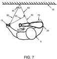
- Fig. 7 illustrates an example of Fig. 6 in one orthogonal direction, how absolute length calibration can be calculated from angular shift.
- the optical axis is in plane with the Fig. 7 .
- the angle 45 can be calculated from the Field of View multiplied with the ratio of the pixel length from the camera device optical axis 35 to half the pixel length of the image.
- the length per pixel calibration 300 for the camera device 15 viewing plane 55 is calibrated by projecting the camera device 15 , onto the plane with the cosine of the angle 45 .
- the angular shift will decrease the visual length of an object according to projection of the object plane onto the viewing plane.
- the absolute length of an object 20 plane parallel to the mirror 10 will therefore be, the measured length 70 divided by cosine of angle 50 .
- Angle 50 is half of angle 45 .
- Fig. 8 of above example software will find the image of the camera device 155 in an image 105 and determine the location of the camera device 160 in the image.
- the camera device model 170 is looked up in a table or database 120 to find the Field of View 220 .
- the image angle 250 is calculated from the camera device pixel count from the center 210 and the Field of View 220 . This can be transferred to the object angle 355 knowing that the object 20 plane is positioned in a certain way in relation to the mirror 180 , for example parallel to the mirror 10 .
- the pixel count of the object 200, together with the length per pixel calibration 300 , as described above, together with the angle to the object 355 plane will give the absolute length dimensions of the object 360 .
- the angular shift and the perspective can be used together.
- the distance to the camera device viewing plane 55 will be shifted towards the mirror 10 away from the user 5 .
- the distance between the object 20 plane and the viewing plane 55 can be calculated by linear algebra, subtracting the object 20 plane by the viewing plane 55 and multiplying with the unit vector perpendicular to the viewing plane 55, and parallel to the optical axis 35. This distance can then be used to calculate the perspective calibration factor of each point of object 20 plane relative to the viewing plane 55 by the distance to the object 20 plane divided by the distance to the viewing plane 55.
- points in the object 20 plane being closer to the camera device 15 will be at a closer distance to the viewing plane 55 than points in the object 20 plane father from the camera device 15.
- Fig. 7 will the hand on the arm 20 appear larger, and the shoulder of the arm 20 appears smaller on the image and the perspective calibration factor will be accordingly the inverse of those distances.
- Fig. 9 illustrates a camera device 15 using a gyroscope or a magnetometer to calculate the angular tilt of the reflecting object used to calculate angular shift.
- the example can calibrate the angle for the mirror 10, and use the information for the viewing plane 55 and an object 20 plane to calibrate the object 20 plane in the image when the object 20 plane is known in regard to a common coordinate system.
- the camera device 15 contains a gyroscope or a magnetometer 115, which can register the angular tilt 80 of the camera device 15.
- the user 5 plane can be assumed to be known, either by instructions or empirical/statistical values, e.g. that the user 5 is standing straight.
- the mirror 10 will have the same angular tilt 75 as the camera device's 15 angular tilt 80, if the camera device 15 is on the optical axis 35.
- the object in this example will have the negative angular tilt to the image plane as the camera device tilt 80.
- Angle and perspective of the user 5 regarding to the viewing plane 55 can be calibrated in the same manner as explained above.
- Fig. 10 illustrates a block diagram of image software for an image taken with a gyroscope or magnetometer, how software can be used for measuring the absolute length for a part of an image with a tilted mirror.
- the angular tilt of the camera device 15 can be registered by a gyroscope or magnetometer 115 at the same time as the image 105 is captured or by metadata 110.
- Calculation of the viewing angle 250, mentioned above, together with the camera device angle 165, will give the mirror angle 255.
- Knowledge of the user vertical position 185 can be looked up internally in a database or on the web 125 from instructions or empirical/statistical values. These data 185 together with the mirror angle 255, will give the object angle 355.
- Calculated length per pixel calibration 300, together with the pixel count of the object 200, and the object angle 355, gives the absolute length dimensions of the object 360.
- Angular shift and perspective can be calculated and used for this embodiment of invention in the way described before.
- a camera device 15 is used as a remote control device 16 for another capturing camera device 17, e.g. a tablet PC, which is paired with the remote control device 16 e.g. by Wi-Fi, Bluetooth, or Infrared connection.
- the image meta data or the software will have information about the remote control device 16.
- the calibration for an object 20, not shown in the figure can use any of the characteristics 25 of the remote control device 16, or a digital calibration image 30 on the remote control device 16, or the remote control device itself 16. The calibration is conducted in the same manner as described in Fig 1 to Fig 3 .
- the tilt 90 of the remote control device 16 together with the tilt 85 of the capturing camera device 17 can also be used to specify the length per pixel calibration 300 of the remote control device 16 by the cosine relation as mentioned earlier.
- the tilt 85 of the capturing camera device 17 can also be used to calculate angular shift and perspective, of the object 20 as mentioned earlier. This is because the angle between the user 5 and the optical axis 35 is known, by knowing e.g. that the user 5 or the object 185 is in a vertical position.
Landscapes
- Engineering & Computer Science (AREA)
- Physics & Mathematics (AREA)
- General Physics & Mathematics (AREA)
- Radar, Positioning & Navigation (AREA)
- Remote Sensing (AREA)
- Multimedia (AREA)
- Manufacturing & Machinery (AREA)
- Health & Medical Sciences (AREA)
- Biomedical Technology (AREA)
- General Health & Medical Sciences (AREA)
- Signal Processing (AREA)
- Length Measuring Devices By Optical Means (AREA)
Claims (4)
- Procédé pour réaliser un étalonnage de longueur absolue pour un objet (20) situé avec un appareil photo dans un miroir ou un objet recouvert par un appareil photo (15) dans un miroir (10), le procédé comprenant les étapes consistant à :- déterminer une longueur de l'appareil photo (15) sur la base du type de l'appareil photo (15),- capturer une image, en utilisant l'appareil photo (15), de l'appareil photo (15) et de l'objet (20) dans le miroir,- mesurer une longueur de l'image de l'objet (20) et mesurer la longueur de l'image de l'appareil photo (15) à partir de l'image capturée,- diviser la longueur déterminée de l'appareil photo (15) par la longueur mesurée de l'image de l'appareil photo (15) pour obtenir un facteur d'étalonnage et- multiplier la longueur mesurée de l'image de l'objet (20) par le facteur d'étalonnage afin d'étalonner la longueur de l'objet (20).
- Procédé selon la revendication 1, dans lequel la longueur de l'appareil photo (15) comprend le diamètre de la lentille de l'appareil photo (15), la longueur de la lentille au bord de l'appareil photo (15), la largeur de l'appareil photo (15), la hauteur de l'appareil photo (15), la longueur d'un écran sur l'appareil photo (15), la largeur d'un écran sur l'appareil photo (15), une longueur d'un motif sur l'appareil photo (15) ou une longueur d'un objet d'étalonnage numérique sur écran (30) qui est présenté sur un écran de l'appareil photo (15).
- Appareil photo (15) pour effectuer un étalonnage de longueur absolue pour un objet (20) situé avec ou revêtu par l'appareil photo (15) dans un miroir (10), l'appareil photo (15) comprenant :- des moyens pour déterminer une longueur de l'appareil photo (15) sur la base du type de l'appareil photo (15),- des moyens pour capturer une image de l'appareil photo (15) et de l'objet (20),- des moyens pour mesurer une longueur de l'image de l'objet (20) et mesurer la longueur de l'image de l'appareil photo (15) à partir de l'image capturée,- des moyens pour diviser la longueur déterminée de l'appareil photo (15) par la longueur mesurée de l'image de l'appareil photo (15) pour obtenir un facteur d'étalonnage et- des moyens pour multiplier la longueur mesurée de l'image de l'objet (20) par le facteur d'étalonnage pour étalonner la longueur de l'objet (20).
- Appareil photo (15) selon la revendication 3, dans lequel la longueur de l'appareil photo (15) comprend le diamètre de la lentille de l'appareil photo (15), la longueur de la lentille au bord de l'appareil photo (15), la largeur de l'appareil photo (15), la hauteur de l'appareil photo (15), la longueur d'un écran sur l'appareil photo (15), la largeur d'un écran sur l'appareil photo (15), une longueur d'un motif sur l'appareil photo (15) ou une longueur d'un objet d'étalonnage numérique sur écran (30) qui est présenté sur un écran de l'appareil photo (15).
Applications Claiming Priority (2)
| Application Number | Priority Date | Filing Date | Title |
|---|---|---|---|
| DKPA201200590 | 2012-10-01 | ||
| PCT/DK2013/000062 WO2014053137A1 (fr) | 2012-10-01 | 2013-09-30 | Procédé d'étalonnage d'un appareil photo |
Publications (3)
| Publication Number | Publication Date |
|---|---|
| EP2904349A1 EP2904349A1 (fr) | 2015-08-12 |
| EP2904349A4 EP2904349A4 (fr) | 2016-05-25 |
| EP2904349B1 true EP2904349B1 (fr) | 2020-03-18 |
Family
ID=50434368
Family Applications (1)
| Application Number | Title | Priority Date | Filing Date |
|---|---|---|---|
| EP13843369.3A Active EP2904349B1 (fr) | 2012-10-01 | 2013-09-30 | Procédé d'étalonnage d'un appareil photo |
Country Status (3)
| Country | Link |
|---|---|
| US (2) | US9667955B2 (fr) |
| EP (1) | EP2904349B1 (fr) |
| WO (1) | WO2014053137A1 (fr) |
Cited By (1)
| Publication number | Priority date | Publication date | Assignee | Title |
|---|---|---|---|---|
| US12183039B2 (en) | 2022-04-11 | 2024-12-31 | Microsoft Technology Licensing, Llc | Camera calibration |
Families Citing this family (12)
| Publication number | Priority date | Publication date | Assignee | Title |
|---|---|---|---|---|
| EP2904349B1 (fr) * | 2012-10-01 | 2020-03-18 | Bodybarista ApS | Procédé d'étalonnage d'un appareil photo |
| KR101383818B1 (ko) * | 2013-11-05 | 2014-04-08 | 최진원 | 모바일 단말기를 이용한 길이 측정 방법 및 시스템 |
| US9784576B2 (en) * | 2015-12-28 | 2017-10-10 | Automotive Research & Test Center | Calibration method for merging object coordinates and calibration board device using the same |
| US10339662B2 (en) | 2016-05-23 | 2019-07-02 | Microsoft Technology Licensing, Llc | Registering cameras with virtual fiducials |
| US10326979B2 (en) | 2016-05-23 | 2019-06-18 | Microsoft Technology Licensing, Llc | Imaging system comprising real-time image registration |
| US10027954B2 (en) * | 2016-05-23 | 2018-07-17 | Microsoft Technology Licensing, Llc | Registering cameras in a multi-camera imager |
| FR3060735B1 (fr) * | 2016-12-15 | 2019-12-27 | IFP Energies Nouvelles | Procede de mesure d'une partie du corps a partir de photographies numeriques, et mise en oeuvre d'un tel procede pour la fabrication de chaussures sur mesure |
| CN106959690B (zh) * | 2017-02-13 | 2020-11-20 | 北京百度网讯科技有限公司 | 无人驾驶车辆的寻找方法、装置、设备及存储介质 |
| CN107749981B (zh) * | 2017-11-15 | 2024-01-30 | 歌尔光学科技有限公司 | 摄像头视场角测量方法及系统 |
| WO2021159109A1 (fr) * | 2020-02-07 | 2021-08-12 | Lgc Us Asset Holdings, Llc | Système et procédé pour accélérer la production de joints de remplacement |
| CN112833780A (zh) * | 2020-12-31 | 2021-05-25 | 吉林大学 | 基于移动智能终端以及ARCore的非接触式快递包裹体积测量方法 |
| JP7797791B2 (ja) * | 2021-06-29 | 2026-01-14 | 大日本印刷株式会社 | 測定システム、表示端末、撮影端末、サーバ、測定方法、測定プログラム |
Family Cites Families (16)
| Publication number | Priority date | Publication date | Assignee | Title |
|---|---|---|---|---|
| DE19822567A1 (de) * | 1997-05-21 | 1998-11-26 | Salzgitter Ag | Verfahren und Meßanordnung zur berührungslosen Messung des Abstandes und der Breitenausdehnung eines Gegenstandes zu einer spiegelnden Oberfläche |
| EP2267656A3 (fr) * | 1998-07-31 | 2012-09-26 | Panasonic Corporation | Appareil d'affichage d'images et procédé d'affichage d'images |
| EP1402230A1 (fr) * | 2001-06-29 | 2004-03-31 | Square D Company | Systeme et procede aeriens de dimensionnement |
| JP4147059B2 (ja) * | 2002-07-03 | 2008-09-10 | 株式会社トプコン | キャリブレーション用データ測定装置、測定方法及び測定プログラム、並びにコンピュータ読取可能な記録媒体、画像データ処理装置 |
| US8218000B2 (en) * | 2002-09-13 | 2012-07-10 | Leica Instruments (Singapore) Pte. Ltd. | Method and system for size calibration |
| US6943754B2 (en) * | 2002-09-27 | 2005-09-13 | The Boeing Company | Gaze tracking system, eye-tracking assembly and an associated method of calibration |
| JP3906194B2 (ja) * | 2002-11-29 | 2007-04-18 | 株式会社東芝 | キャリブレーション方法、キャリブレーション支援装置、キャリブレーション装置およびカメラシステムの製造方法 |
| US10109315B2 (en) * | 2005-03-01 | 2018-10-23 | Eyesmatch Ltd | Devices, systems and methods for auto-delay video presentation |
| US7496241B1 (en) * | 2005-09-08 | 2009-02-24 | Goodrich Corporation | Precision optical systems with performance characterization and uses thereof |
| DE102007030378A1 (de) * | 2007-06-29 | 2009-01-02 | Spatial View Gmbh Dresden | System zur Bestimmung der Lage eines Kamerasystems |
| DE102010004233B3 (de) * | 2010-01-08 | 2011-07-07 | Deutsches Zentrum für Luft- und Raumfahrt e.V., 51147 | Verfahren zur Bestimmung der Lage eines Kamerasystems bezüglich eines Objekts |
| US8676050B2 (en) * | 2010-12-29 | 2014-03-18 | Gary S. Shuster | Autofocus calibration for long lenses |
| US8941561B1 (en) * | 2012-01-06 | 2015-01-27 | Google Inc. | Image capture |
| EP2904349B1 (fr) * | 2012-10-01 | 2020-03-18 | Bodybarista ApS | Procédé d'étalonnage d'un appareil photo |
| US9239460B2 (en) * | 2013-05-10 | 2016-01-19 | Microsoft Technology Licensing, Llc | Calibration of eye location |
| US10318976B2 (en) * | 2015-07-28 | 2019-06-11 | Walmart Apollo, Llc | Methods for determining measurement data of an item |
-
2013
- 2013-09-30 EP EP13843369.3A patent/EP2904349B1/fr active Active
- 2013-09-30 US US14/432,960 patent/US9667955B2/en active Active
- 2013-09-30 WO PCT/DK2013/000062 patent/WO2014053137A1/fr not_active Ceased
-
2017
- 2017-05-17 US US15/597,915 patent/US10506225B2/en not_active Expired - Fee Related
Non-Patent Citations (1)
| Title |
|---|
| None * |
Cited By (1)
| Publication number | Priority date | Publication date | Assignee | Title |
|---|---|---|---|---|
| US12183039B2 (en) | 2022-04-11 | 2024-12-31 | Microsoft Technology Licensing, Llc | Camera calibration |
Also Published As
| Publication number | Publication date |
|---|---|
| EP2904349A1 (fr) | 2015-08-12 |
| EP2904349A4 (fr) | 2016-05-25 |
| US20170251206A1 (en) | 2017-08-31 |
| US9667955B2 (en) | 2017-05-30 |
| WO2014053137A1 (fr) | 2014-04-10 |
| US10506225B2 (en) | 2019-12-10 |
| US20150249822A1 (en) | 2015-09-03 |
Similar Documents
| Publication | Publication Date | Title |
|---|---|---|
| EP2904349B1 (fr) | Procédé d'étalonnage d'un appareil photo | |
| US10825198B2 (en) | 3 dimensional coordinates calculating apparatus, 3 dimensional coordinates calculating method, 3 dimensional distance measuring apparatus and 3 dimensional distance measuring method using images | |
| JP6195915B2 (ja) | 画像計測装置 | |
| US7193626B2 (en) | Device and method for displaying stereo image | |
| US11015930B2 (en) | Method for 2D picture based conglomeration in 3D surveying | |
| US10277889B2 (en) | Method and system for depth estimation based upon object magnification | |
| CN104279960B (zh) | 用移动设备进行物体尺寸测量的方法 | |
| CN101464132B (zh) | 位置确定方法及位置确定装置 | |
| CN102012625A (zh) | 根据单个相机和运动传感器的3d信息推导 | |
| CN106643699A (zh) | 一种虚拟现实系统中的空间定位装置和定位方法 | |
| CN102927917B (zh) | 多目铁塔视觉测量方法 | |
| JP2017098859A (ja) | 画像のキャリブレーション装置及びキャリブレーション方法 | |
| US20130331145A1 (en) | Measuring system for mobile three dimensional imaging system | |
| CN206300653U (zh) | 一种虚拟现实系统中的空间定位装置 | |
| CN112805607A (zh) | 计测装置、计测方法和显微镜系统 | |
| KR20210037047A (ko) | 스마트 단말기를 이용한 옥외광고물의 면적 측정 방법 | |
| KR101996226B1 (ko) | 피사체의 3차원 위치 측정 장치 및 그 방법 | |
| JP2009299241A (ja) | 身体寸法測定装置 | |
| CN110375717A (zh) | 一种实时面积量算的近景摄影测量方法 | |
| KR20160147159A (ko) | 스마트 단말기 및 그것을 이용한 피사체 길이 측정 방법 | |
| Kainz et al. | Estimation of camera intrinsic matrix parameters and its utilization in the extraction of dimensional units | |
| CN210321726U (zh) | 一种实时面积量算的近景摄影测量装置 | |
| CN116678370B (zh) | 一种基于矩形信息的单目视觉平面测距方法 | |
| GB2470203A (en) | Camera having an integral image based object measurement facility | |
| TWI516744B (zh) | 距離估算系統、距離估算方法及電腦可讀取媒體 |
Legal Events
| Date | Code | Title | Description |
|---|---|---|---|
| PUAI | Public reference made under article 153(3) epc to a published international application that has entered the european phase |
Free format text: ORIGINAL CODE: 0009012 |
|
| 17P | Request for examination filed |
Effective date: 20150430 |
|
| AK | Designated contracting states |
Kind code of ref document: A1 Designated state(s): AL AT BE BG CH CY CZ DE DK EE ES FI FR GB GR HR HU IE IS IT LI LT LU LV MC MK MT NL NO PL PT RO RS SE SI SK SM TR |
|
| AX | Request for extension of the european patent |
Extension state: BA ME |
|
| DAX | Request for extension of the european patent (deleted) | ||
| RIN1 | Information on inventor provided before grant (corrected) |
Inventor name: FALK, PETER |
|
| RA4 | Supplementary search report drawn up and despatched (corrected) |
Effective date: 20160422 |
|
| RIC1 | Information provided on ipc code assigned before grant |
Ipc: G01B 21/04 20060101ALI20160418BHEP Ipc: G01C 11/00 20060101ALI20160418BHEP Ipc: G01C 25/00 20060101ALI20160418BHEP Ipc: G01B 11/02 20060101AFI20160418BHEP |
|
| STAA | Information on the status of an ep patent application or granted ep patent |
Free format text: STATUS: EXAMINATION IS IN PROGRESS |
|
| 17Q | First examination report despatched |
Effective date: 20180813 |
|
| GRAP | Despatch of communication of intention to grant a patent |
Free format text: ORIGINAL CODE: EPIDOSNIGR1 |
|
| STAA | Information on the status of an ep patent application or granted ep patent |
Free format text: STATUS: GRANT OF PATENT IS INTENDED |
|
| INTG | Intention to grant announced |
Effective date: 20190911 |
|
| GRAS | Grant fee paid |
Free format text: ORIGINAL CODE: EPIDOSNIGR3 |
|
| GRAA | (expected) grant |
Free format text: ORIGINAL CODE: 0009210 |
|
| STAA | Information on the status of an ep patent application or granted ep patent |
Free format text: STATUS: THE PATENT HAS BEEN GRANTED |
|
| RAP1 | Party data changed (applicant data changed or rights of an application transferred) |
Owner name: BODYBARISTA APS |
|
| AK | Designated contracting states |
Kind code of ref document: B1 Designated state(s): AL AT BE BG CH CY CZ DE DK EE ES FI FR GB GR HR HU IE IS IT LI LT LU LV MC MK MT NL NO PL PT RO RS SE SI SK SM TR |
|
| REG | Reference to a national code |
Ref country code: GB Ref legal event code: FG4D |
|
| REG | Reference to a national code |
Ref country code: DE Ref legal event code: R096 Ref document number: 602013067029 Country of ref document: DE |
|
| REG | Reference to a national code |
Ref country code: AT Ref legal event code: REF Ref document number: 1246393 Country of ref document: AT Kind code of ref document: T Effective date: 20200415 Ref country code: IE Ref legal event code: FG4D |
|
| PG25 | Lapsed in a contracting state [announced via postgrant information from national office to epo] |
Ref country code: RS Free format text: LAPSE BECAUSE OF FAILURE TO SUBMIT A TRANSLATION OF THE DESCRIPTION OR TO PAY THE FEE WITHIN THE PRESCRIBED TIME-LIMIT Effective date: 20200318 Ref country code: FI Free format text: LAPSE BECAUSE OF FAILURE TO SUBMIT A TRANSLATION OF THE DESCRIPTION OR TO PAY THE FEE WITHIN THE PRESCRIBED TIME-LIMIT Effective date: 20200318 Ref country code: NO Free format text: LAPSE BECAUSE OF FAILURE TO SUBMIT A TRANSLATION OF THE DESCRIPTION OR TO PAY THE FEE WITHIN THE PRESCRIBED TIME-LIMIT Effective date: 20200618 |
|
| REG | Reference to a national code |
Ref country code: NL Ref legal event code: MP Effective date: 20200318 |
|
| PG25 | Lapsed in a contracting state [announced via postgrant information from national office to epo] |
Ref country code: BG Free format text: LAPSE BECAUSE OF FAILURE TO SUBMIT A TRANSLATION OF THE DESCRIPTION OR TO PAY THE FEE WITHIN THE PRESCRIBED TIME-LIMIT Effective date: 20200618 Ref country code: GR Free format text: LAPSE BECAUSE OF FAILURE TO SUBMIT A TRANSLATION OF THE DESCRIPTION OR TO PAY THE FEE WITHIN THE PRESCRIBED TIME-LIMIT Effective date: 20200619 Ref country code: HR Free format text: LAPSE BECAUSE OF FAILURE TO SUBMIT A TRANSLATION OF THE DESCRIPTION OR TO PAY THE FEE WITHIN THE PRESCRIBED TIME-LIMIT Effective date: 20200318 Ref country code: LV Free format text: LAPSE BECAUSE OF FAILURE TO SUBMIT A TRANSLATION OF THE DESCRIPTION OR TO PAY THE FEE WITHIN THE PRESCRIBED TIME-LIMIT Effective date: 20200318 Ref country code: SE Free format text: LAPSE BECAUSE OF FAILURE TO SUBMIT A TRANSLATION OF THE DESCRIPTION OR TO PAY THE FEE WITHIN THE PRESCRIBED TIME-LIMIT Effective date: 20200318 |
|
| REG | Reference to a national code |
Ref country code: LT Ref legal event code: MG4D |
|
| PG25 | Lapsed in a contracting state [announced via postgrant information from national office to epo] |
Ref country code: NL Free format text: LAPSE BECAUSE OF FAILURE TO SUBMIT A TRANSLATION OF THE DESCRIPTION OR TO PAY THE FEE WITHIN THE PRESCRIBED TIME-LIMIT Effective date: 20200318 |
|
| PG25 | Lapsed in a contracting state [announced via postgrant information from national office to epo] |
Ref country code: PT Free format text: LAPSE BECAUSE OF FAILURE TO SUBMIT A TRANSLATION OF THE DESCRIPTION OR TO PAY THE FEE WITHIN THE PRESCRIBED TIME-LIMIT Effective date: 20200812 Ref country code: EE Free format text: LAPSE BECAUSE OF FAILURE TO SUBMIT A TRANSLATION OF THE DESCRIPTION OR TO PAY THE FEE WITHIN THE PRESCRIBED TIME-LIMIT Effective date: 20200318 Ref country code: SM Free format text: LAPSE BECAUSE OF FAILURE TO SUBMIT A TRANSLATION OF THE DESCRIPTION OR TO PAY THE FEE WITHIN THE PRESCRIBED TIME-LIMIT Effective date: 20200318 Ref country code: SK Free format text: LAPSE BECAUSE OF FAILURE TO SUBMIT A TRANSLATION OF THE DESCRIPTION OR TO PAY THE FEE WITHIN THE PRESCRIBED TIME-LIMIT Effective date: 20200318 Ref country code: RO Free format text: LAPSE BECAUSE OF FAILURE TO SUBMIT A TRANSLATION OF THE DESCRIPTION OR TO PAY THE FEE WITHIN THE PRESCRIBED TIME-LIMIT Effective date: 20200318 Ref country code: CZ Free format text: LAPSE BECAUSE OF FAILURE TO SUBMIT A TRANSLATION OF THE DESCRIPTION OR TO PAY THE FEE WITHIN THE PRESCRIBED TIME-LIMIT Effective date: 20200318 Ref country code: IS Free format text: LAPSE BECAUSE OF FAILURE TO SUBMIT A TRANSLATION OF THE DESCRIPTION OR TO PAY THE FEE WITHIN THE PRESCRIBED TIME-LIMIT Effective date: 20200718 Ref country code: LT Free format text: LAPSE BECAUSE OF FAILURE TO SUBMIT A TRANSLATION OF THE DESCRIPTION OR TO PAY THE FEE WITHIN THE PRESCRIBED TIME-LIMIT Effective date: 20200318 |
|
| REG | Reference to a national code |
Ref country code: AT Ref legal event code: MK05 Ref document number: 1246393 Country of ref document: AT Kind code of ref document: T Effective date: 20200318 |
|
| REG | Reference to a national code |
Ref country code: DE Ref legal event code: R097 Ref document number: 602013067029 Country of ref document: DE |
|
| PLBE | No opposition filed within time limit |
Free format text: ORIGINAL CODE: 0009261 |
|
| STAA | Information on the status of an ep patent application or granted ep patent |
Free format text: STATUS: NO OPPOSITION FILED WITHIN TIME LIMIT |
|
| PG25 | Lapsed in a contracting state [announced via postgrant information from national office to epo] |
Ref country code: DK Free format text: LAPSE BECAUSE OF FAILURE TO SUBMIT A TRANSLATION OF THE DESCRIPTION OR TO PAY THE FEE WITHIN THE PRESCRIBED TIME-LIMIT Effective date: 20200318 Ref country code: IT Free format text: LAPSE BECAUSE OF FAILURE TO SUBMIT A TRANSLATION OF THE DESCRIPTION OR TO PAY THE FEE WITHIN THE PRESCRIBED TIME-LIMIT Effective date: 20200318 Ref country code: AT Free format text: LAPSE BECAUSE OF FAILURE TO SUBMIT A TRANSLATION OF THE DESCRIPTION OR TO PAY THE FEE WITHIN THE PRESCRIBED TIME-LIMIT Effective date: 20200318 Ref country code: ES Free format text: LAPSE BECAUSE OF FAILURE TO SUBMIT A TRANSLATION OF THE DESCRIPTION OR TO PAY THE FEE WITHIN THE PRESCRIBED TIME-LIMIT Effective date: 20200318 |
|
| 26N | No opposition filed |
Effective date: 20201221 |
|
| PG25 | Lapsed in a contracting state [announced via postgrant information from national office to epo] |
Ref country code: PL Free format text: LAPSE BECAUSE OF FAILURE TO SUBMIT A TRANSLATION OF THE DESCRIPTION OR TO PAY THE FEE WITHIN THE PRESCRIBED TIME-LIMIT Effective date: 20200318 |
|
| PG25 | Lapsed in a contracting state [announced via postgrant information from national office to epo] |
Ref country code: MC Free format text: LAPSE BECAUSE OF FAILURE TO SUBMIT A TRANSLATION OF THE DESCRIPTION OR TO PAY THE FEE WITHIN THE PRESCRIBED TIME-LIMIT Effective date: 20200318 |
|
| REG | Reference to a national code |
Ref country code: CH Ref legal event code: PL |
|
| PG25 | Lapsed in a contracting state [announced via postgrant information from national office to epo] |
Ref country code: SI Free format text: LAPSE BECAUSE OF FAILURE TO SUBMIT A TRANSLATION OF THE DESCRIPTION OR TO PAY THE FEE WITHIN THE PRESCRIBED TIME-LIMIT Effective date: 20200318 |
|
| REG | Reference to a national code |
Ref country code: BE Ref legal event code: MM Effective date: 20200930 |
|
| PG25 | Lapsed in a contracting state [announced via postgrant information from national office to epo] |
Ref country code: LU Free format text: LAPSE BECAUSE OF NON-PAYMENT OF DUE FEES Effective date: 20200930 |
|
| PG25 | Lapsed in a contracting state [announced via postgrant information from national office to epo] |
Ref country code: CH Free format text: LAPSE BECAUSE OF NON-PAYMENT OF DUE FEES Effective date: 20200930 Ref country code: BE Free format text: LAPSE BECAUSE OF NON-PAYMENT OF DUE FEES Effective date: 20200930 Ref country code: LI Free format text: LAPSE BECAUSE OF NON-PAYMENT OF DUE FEES Effective date: 20200930 Ref country code: IE Free format text: LAPSE BECAUSE OF NON-PAYMENT OF DUE FEES Effective date: 20200930 |
|
| PGFP | Annual fee paid to national office [announced via postgrant information from national office to epo] |
Ref country code: FR Payment date: 20210921 Year of fee payment: 9 |
|
| PGFP | Annual fee paid to national office [announced via postgrant information from national office to epo] |
Ref country code: DE Payment date: 20210920 Year of fee payment: 9 Ref country code: GB Payment date: 20210920 Year of fee payment: 9 |
|
| PG25 | Lapsed in a contracting state [announced via postgrant information from national office to epo] |
Ref country code: TR Free format text: LAPSE BECAUSE OF FAILURE TO SUBMIT A TRANSLATION OF THE DESCRIPTION OR TO PAY THE FEE WITHIN THE PRESCRIBED TIME-LIMIT Effective date: 20200318 Ref country code: MT Free format text: LAPSE BECAUSE OF FAILURE TO SUBMIT A TRANSLATION OF THE DESCRIPTION OR TO PAY THE FEE WITHIN THE PRESCRIBED TIME-LIMIT Effective date: 20200318 Ref country code: CY Free format text: LAPSE BECAUSE OF FAILURE TO SUBMIT A TRANSLATION OF THE DESCRIPTION OR TO PAY THE FEE WITHIN THE PRESCRIBED TIME-LIMIT Effective date: 20200318 |
|
| PG25 | Lapsed in a contracting state [announced via postgrant information from national office to epo] |
Ref country code: MK Free format text: LAPSE BECAUSE OF FAILURE TO SUBMIT A TRANSLATION OF THE DESCRIPTION OR TO PAY THE FEE WITHIN THE PRESCRIBED TIME-LIMIT Effective date: 20200318 Ref country code: AL Free format text: LAPSE BECAUSE OF FAILURE TO SUBMIT A TRANSLATION OF THE DESCRIPTION OR TO PAY THE FEE WITHIN THE PRESCRIBED TIME-LIMIT Effective date: 20200318 |
|
| REG | Reference to a national code |
Ref country code: DE Ref legal event code: R119 Ref document number: 602013067029 Country of ref document: DE |
|
| GBPC | Gb: european patent ceased through non-payment of renewal fee |
Effective date: 20220930 |
|
| PG25 | Lapsed in a contracting state [announced via postgrant information from national office to epo] |
Ref country code: FR Free format text: LAPSE BECAUSE OF NON-PAYMENT OF DUE FEES Effective date: 20220930 Ref country code: DE Free format text: LAPSE BECAUSE OF NON-PAYMENT OF DUE FEES Effective date: 20230401 |
|
| PG25 | Lapsed in a contracting state [announced via postgrant information from national office to epo] |
Ref country code: GB Free format text: LAPSE BECAUSE OF NON-PAYMENT OF DUE FEES Effective date: 20220930 |