EP2904362B1 - Kraft und drehmoment-sensoren - Google Patents
Kraft und drehmoment-sensoren Download PDFInfo
- Publication number
- EP2904362B1 EP2904362B1 EP13838077.9A EP13838077A EP2904362B1 EP 2904362 B1 EP2904362 B1 EP 2904362B1 EP 13838077 A EP13838077 A EP 13838077A EP 2904362 B1 EP2904362 B1 EP 2904362B1
- Authority
- EP
- European Patent Office
- Prior art keywords
- load
- strain gauges
- bearing member
- strain
- sensor
- Prior art date
- Legal status (The legal status is an assumption and is not a legal conclusion. Google has not performed a legal analysis and makes no representation as to the accuracy of the status listed.)
- Active
Links
Images




Classifications
-
- G—PHYSICS
- G01—MEASURING; TESTING
- G01L—MEASURING FORCE, STRESS, TORQUE, WORK, MECHANICAL POWER, MECHANICAL EFFICIENCY, OR FLUID PRESSURE
- G01L5/00—Apparatus for, or methods of, measuring force, work, mechanical power, or torque, specially adapted for specific purposes
- G01L5/22—Apparatus for, or methods of, measuring force, work, mechanical power, or torque, specially adapted for specific purposes for measuring the force applied to control members, e.g. control members of vehicles, triggers
- G01L5/226—Apparatus for, or methods of, measuring force, work, mechanical power, or torque, specially adapted for specific purposes for measuring the force applied to control members, e.g. control members of vehicles, triggers to manipulators, e.g. the force due to gripping
-
- G—PHYSICS
- G01—MEASURING; TESTING
- G01L—MEASURING FORCE, STRESS, TORQUE, WORK, MECHANICAL POWER, MECHANICAL EFFICIENCY, OR FLUID PRESSURE
- G01L1/00—Measuring force or stress, in general
- G01L1/20—Measuring force or stress, in general by measuring variations in ohmic resistance of solid materials or of electrically-conductive fluids; by making use of electrokinetic cells, i.e. liquid-containing cells wherein an electrical potential is produced or varied upon the application of stress
- G01L1/22—Measuring force or stress, in general by measuring variations in ohmic resistance of solid materials or of electrically-conductive fluids; by making use of electrokinetic cells, i.e. liquid-containing cells wherein an electrical potential is produced or varied upon the application of stress using resistance strain gauges
- G01L1/2268—Arrangements for correcting or for compensating unwanted effects
- G01L1/2281—Arrangements for correcting or for compensating unwanted effects for temperature variations
-
- G—PHYSICS
- G01—MEASURING; TESTING
- G01L—MEASURING FORCE, STRESS, TORQUE, WORK, MECHANICAL POWER, MECHANICAL EFFICIENCY, OR FLUID PRESSURE
- G01L5/00—Apparatus for, or methods of, measuring force, work, mechanical power, or torque, specially adapted for specific purposes
- G01L5/16—Apparatus for, or methods of, measuring force, work, mechanical power, or torque, specially adapted for specific purposes for measuring several components of force
- G01L5/161—Apparatus for, or methods of, measuring force, work, mechanical power, or torque, specially adapted for specific purposes for measuring several components of force using variations in ohmic resistance
- G01L5/1627—Apparatus for, or methods of, measuring force, work, mechanical power, or torque, specially adapted for specific purposes for measuring several components of force using variations in ohmic resistance of strain gauges
Definitions
- the inventive concepts relate to sensors for measuring physical forces and torques.
- Force and torque sensors are commonly used to determine the physical forces and torques, i.e., moments, acting on a mechanical element or structure.
- Force and torque sensors typically include a load-bearing element, or flexure, and a plurality of strain gauges mounted on the flexure. The sensor is mounted so that the flexure is subjected to the forces and moments to be measured. The forces and moments, when applied to the flexure, induce deflection, or strain, in the flexure. Because the strain gauges are mounted on the flexure, the strain gauges themselves undergo strain in response to the strain experienced by the flexure, and the strain gauges generate outputs responsive to this strain. These outputs can be correlated to the magnitudes of the forces and moments acting on the flexure through predetermined data developed though a calibration process conducted on the sensor.
- Force and torque sensors capable of measuring forces and torques acting in multiple directions typically include a relatively large number of active strain gauges, e.g., six axis force/torque sensors often include twenty or more.
- the use of a large number of strain gauges is typically necessary in order to allow the sensor to compensate for strain in the flexure induced by changes in the temperature of the flexure.
- the use of a large number of strain gages makes the sensors more complex, costly, and difficult to manufacture.
- the flexures of such multi-axis sensors often have complex geometries in order to accommodate the strain gauges in specific orientations needed to measure multi-dimensional strain of the flexure.
- the complex flexure design can drive the overall size and weight of the flexure to undesirably high levels.
- the method consists in measuring the signals delivered by the three strain-gage bridges in the absence of any load applied on the measuring element, then under a number of known reference loads chosen from among those to which each strain-gage bridge is the most sensitive.
- the reference measurements are used as a basis for calculating the parameters of sensitivity according to which each of the signals delivered by the measuring bridges is a function of the applied loads.
- these parameters of sensitivity are used as a basis for calculating the correction to be made in the force or the moment measured by the first strain-gage bridge.
- the invention is a sensor for measuring three orthogonal external forces and torques according to claim 1.
- Sensors for measuring forces and torques include a load-bearing member having a longitudinal axis extending in a first direction, and a first and a second strain gauge mounted on a surface of the load-bearing member.
- the first and second strain gauges are symmetrically disposed about a line of symmetry on the outer surface of the load-bearing member.
- the line of symmetry extends substantially in the first direction, and a sensing axis of the first strain gauge is angularly offset from the line of symmetry by a first angle having a value between zero and 90°.
- the computer-executable instructions are configured so that the computer-executable instructions, when executed by the processor, cause the processor to calculate a plurality of forces and torques acting on the load-bearing member at a load condition.
- the calculations are based on responses of the strain gauges to the load condition, and a rectangular matrix of predetermined calibration data relating the forces and torques to response characteristics of the strain gauges.
- inventive concepts are described with reference to the attached figures.
- the figures are not drawn to scale and they are provided merely to illustrate the instant inventive concepts.
- Several aspects of the inventive concepts are described below with reference to example applications for illustration. It should be understood that numerous specific details, relationships, and methods are set forth to provide a full understanding of the inventive concepts.
- inventive concepts can be practiced without one or more of the specific details or with other methods.
- well-known structures or operation are not shown in detail to avoid obscuring the inventive concepts.
- inventive concepts is not limited by the illustrated ordering of acts or events, as some acts may occur in different orders and/or concurrently with other acts or events.
- not all illustrated acts or events are required to implement a methodology in accordance with the inventive concepts.
- the sensor 10 forms part of a robotic device 100, depicted in FIGs. 1-3 .
- the robotic device 100 includes an arm 102 mounted on a body 104 as shown in FIG. 1 .
- the arm 102 has multiple joints 106 about which portions of the arm 100 can articulate.
- the robotic device 100 also includes a gripper 108 mounted on an end of the arm 102.
- the gripper 108 includes a body 110.
- the gripper 108 also includes two articulating supports 112 pivotally mounted on the body via respective pins 113 disposed in a circular opening 114 in the support.
- a respective sensor 10 is associated with each of the supports 112.
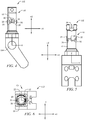
- One of the supports is depicted in detail in FIGs. 4-6 .
- each support 112 forms part of the sensor 10, and acts as a flexure 12, i.e., a load-bearing member the strain of which will be measured to determine the external forces, and external moments, i.e., torques acting on the sensor 10.
- the flexure 12 is depicted by itself in FIG. 7 , and as part of its associated support 112 in FIGs. 4-6 .
- Each gripper 108 also includes two fingers 116 securely mounted on an associated flexure 12 by a suitable means such as mechanical bolting, as shown in FIGs. 1-3 .
- the gripper 108 also includes an electric motor 115, located inside of the gripper body 110 shown in FIGs. 2 and 3 , that is activated in response to input from a control unit (not shown) mounted on the body 104 of the robotic device 100.
- Each support 112 is mechanically coupled to the motor 115 through a set of gears, and pivots about its associated mounting pin 113 in response to activation of the motor 115.
- the pivotal movement of the supports 112 causes the fingers 116 to move toward or away from each other.
- the fingers 116 can thus grasp and release objects in response to coordinated inputs from the control unit.
- Each sensor 10 can measure three orthogonal external forces acting on its associated finger 116, and moments acting on the finger 116 about the three orthogonal axes.
- the force and moment information can be provided to the control unit of the robotic device 100, and can be used by the control unit as feedback to control the positions of the fingers 116 as the fingers grasp, hold, and release objects.
- the use of the sensor 10 in connection with the gripper 108 and the robotic device 100 is disclosed for exemplary purposes only.
- the sensor 10, and variants thereof, can be used to measure forces and moments on other types of devices, including devices other than robotic devices.
- the sensors 10 on each of the supports 112 are substantially identical. For clarity, the sensors 10 will be referred to hereinafter in the singular, and the following description applies to both of the sensors 10.
- the flexure 12 of the sensor 10 has a substantially cylindrical configuration, and has a longitudinal axis that extends substantially in a "z" direction denoted by the orthogonal coordinate system 12 depicted in the figures.
- the flexure 12 can have a shape other than cylindrical in alternative embodiments, provided the shape can permit six or more strain gauges to be disposed symmetrically about, i.e., spaced equally from and oriented similarly in relation to, the longitudinal axis of the flexure 12.
- a cylindrical geometry is particularly advantageous, as cylinders area easy and cheap to manufacture, tend to be very strong, and have no irregular geometry that leads to undesirable stress concentrations within the flexure.
- the sensor 10 further comprises six strain gauges 20 and four strain gauges 22, as depicted in FIGs. 4-8 .
- the strain gauges 20, 22 are mounted on an outer surface of the flexure 12, using a suitable means such as epoxy.
- the strain gauges 20, 22 are mounted proximate a longitudinal, or z-axis midpoint of the flexure 12, so as to be positioned away from stress risers that can occur proximate the ends of the flexure 12.
- An even number of strain gauges 20 greater than six can be used in alternative embodiments.
- the strain gauges 20, 22 can be mounted a surface other than the outer surface of the flexure 12 in alternative embodiments.
- the strain gages 20, 22 can be bonded to a inner surface of the flexure 12 in applications where the flexure 12 has a cylindrical configuration and is large enough to accommodate this type of mounting arrangement.
- strain gauges 20, and their respective gauge factors are substantially identical to each other.
- the strain gauges 22 likewise are substantially identical to each other.
- the strain gauges 20 are substantially identical to the strain gauges 22, but can be different in alternative embodiments.
- the respective outputs of the strain gauges 20 are used to determine the external loads or forces acting on the flexure 12 in the x and y directions, and the moments acting on the flexure 12 about axes extending in the x, y, and z directions. These forces and moments are referred to hereinafter as “F x ,” “F y ,” “M x ,” “M y ,” and the “M z ,” respectively.
- the outputs of the second set 36 of strain gauges 22 are used to determine the forces acting on the flexure 12 in the axial or z direction. This force is referred to hereinafter as "F z .”
- the strain gauges 20, 22 are foil-type strain gauges each comprising a metallic foil configured in a grid pattern and mounted on an electrically-insulative substrate or carrier. Each strain gauge 20, 22 also includes two electrically-conductive leads connected to opposite ends of the foil. The carrier of each strain gauge 20, 22 is bonded to the flexure 12 by a suitable means such as adhesive.
- the strain gauges 20, 22 can be wire strain gauges or semiconductor strain gauges in alternative embodiments.
- Each strain gauge 20, 22 has a sensing axis or principal axis of strain, i.e., an axis coincident with the direction in which the strain gauge 20, 22 is configured to measure strain in the object upon which the strain gauge 20, 22 is mounted. This axis is denoted in FIG. 8 by the reference symbol "x s .”
- the system 10 further comprises a signal conditioning unit 28, depicted schematically in FIG. 9 .
- the signal conditioning unit 28 can be mounted at a suitable location such as on the body of the robotic device 100.
- the signal conditioning unit 28 comprises a voltage source 30, six sets of resistors 34a, 34b, and a voltmeter 36.
- the resistors 34a, 34b have respective resistance values R 1 , R 2 .
- Each strain gauge 20 is associated with a respective one of the sets of resistors 34a, 34b.
- the sensor 10 further includes six strain gauges 35.
- the strain gauges 35 are so-called "dummy" strain gauges used for thermal compensation.
- Each strain gauge 35 has a nominal resistance value R 3 , and is associated with a respective one of the strain gauges 20 and a respective set of resistors 34a, 34b.
- One of the six circuits 38 is illustrated schematically in FIG. 10 .
- Alternative embodiments can incorporate a single dummy gage as part of a half-bridge reference circuit, as opposed to the use of a dummy gage for each strain gage circuit as in the sensor 10.
- the strain gauge 20, strain gauge 35, and resistors 34a, 34b of each circuit 38 are interconnected so as to form a Wheatstone bridge 40 of the quarter-bridge type, as shown in FIG. 10 .
- the voltage source 30 is electrically connected to each circuit 38 as shown in FIG. 10 , so that the voltage source 30 applies an excitation voltage across the associated bridge 40.
- the voltage can be, for example, a five-volt stabilized direct-current (DC) voltage.
- the voltmeter 36 is electrically connected to each circuit 38 as shown in FIG. 10 , so that the voltmeter 36 measures the voltage potential across the bridge 40.
- each strain gauge 20 changes in response to the external forces and moments applied to the flexure 12. This change in resistance causes an imbalance in the Wheatstone bridge 40 of the associated circuit 38, which in turn results in a voltage output across the bridge 40 as measured by the voltmeter 36.
- the voltage output can be related to the magnitude and direction of the force or moment acting on the flexure 12 by a set of predetermined calibration factors, discussed below.
- the voltage outputs of the circuits 38 associated with each of the six strain gauges 20 are referred to hereinafter as v 1 , v 2 , v 3 , v 4 , v 5 , and v 6 , respectively.
- the respective resistance values R 1 , R 2 , and R 3 of the resistors 34a, 34b and the strain gauge 35 are selected so that the Wheatstone bridge 40 of the associated circuit 38, ideally, is balanced, i.e., the voltage potential across the associated bridge 40 is approximately zero, when no external forces or moments are being applied to the flexure 12.
- the resistance values R 1 and R 2 are selected so as to be approximately equal
- the resistance R 3 is selected so as to be approximately equal to the resistance of the associated strain gauge 20 when the flexure 12 is under a no-load, i.e., zero-strain, condition.
- the output voltage of the Wheatstone bridge 40 may be non-zero when the flexure 12 is under a no-load condition, due to factors such as tolerances in the resistance values R 1 and R 2 , strain induced in the strain gauge 20 by the mounting thereof on the flexure 12, thermal effects, etc.
- This offset voltage can be compensated for using suitable techniques, such as an offset-nulling or balancing circuit (not shown) electrically connected to each bridge 40 and configured to provide a voltage that substantially cancels the offset voltage.
- compensation for the offset voltage can be achieved though software that applies a correction to the output voltage of the each circuit 38, based on the offset voltage measured prior to the application of any external forces or moments to the flexure 12.
- the resistors 34a, 34b can be housed within the signal conditioning unit 28, as depicted in FIG. 9 .
- the dummy strain gauges 35 can be mounted at locations proximate the strain gauges 20, so as to provide compensation for drift in the output voltages v 1 -v 6 caused by heating or cooling of the portion of flexure 12 that the strain gauges 20 themselves are bonded to.
- the location for each dummy strain gauge 35 can be selected so that the strain gauge 35 is subject to approximately the same temperature as the associated strain gauge 20, but is not subjected to the strain induced in the flexure 12 due to the external forces and moments acting thereon.
- the strain gauges 35 can be mounted on the support 112 at the location depicted in FIGs. 4 and 6 .
- the strain gauges 20 are mounted on the flexure 12 so that the sensing axes x s thereof are angled in relation to the "z" direction, and the respective mid-points of adjacent strain gauges 20 are equally spaced. Moreover, the strain gauges 20 are disposed symmetrically about the longitudinal or z axis of the flexure 12, i.e., the strain gauges 20 are spaced equally from, and are oriented similarly in relation to the longitudinal axis.
- Adjacent strain gauges 20 are symmetrically disposed substantially about an associated imaginary reference line, or line of symmetry, on the outer surface of the flexure 12.
- the imaginary lines of symmetry are denoted in Fig. 8 by the symbol "s,” and extend substantially in the axial or z direction.
- three of the strain gauges 20 are mounted so that the sensing axes x s thereof are angularly offset from the associated line of symmetry "s" by an angle between 0 and + 90 degrees; this angle is denoted in Fig.
- strain gauges 20 are mounted so that the sensing axes x s thereof are angularly offset from the associated line of symmetry "s" by an angle approximately equal in magnitude to, and opposite in direction from the angle " ⁇ ;” this offset angle is denoted in FIG. 8 by the reference character " ⁇ '.”
- the strain gauges 20 oriented at the angle ⁇ and the strain gauges 20 oriented at the angle ⁇ ' are arranged in an alternating manner around the circumference of the flexure 12.
- the strain gauges 20 are arranged in three pairs, with the strain gauges 20 of each pair forming a mirror image about their associated line of symmetry "s.”
- the angles ⁇ , ⁇ ' can be, for example, approximately +45° and approximately -45°, respectively.
- the optimal or desired values for ⁇ and ⁇ ' can vary by application.
- the magnitudes of ⁇ and ⁇ ' affect the sensitivities of the strain gauges 20 to forces applied to the flexure 12 in the x and y directions, and to moments applied to the flexure 12 about axes extending in the x, y, and z directions.
- the symmetric arrangement of the strain gauges 20 make the external forces and moments F x , F y , M x , M y , and M z determined by the sensor 10 substantially insensitive to drift due to thermally-induced deflection of the flexure 12.
- each of the six strain gauges 20 will be affected in a substantially identical manner by thermally-induced expansion or contraction of the flexure 12.
- any thermally-induced drift in the output voltages v 1 -v 6 of the six circuits 38 will be approximately equal.
- FIG. 12 depicts a five by six transformation, or calibration matrix C 1 that can be used to determine the external forces and moments F x , F y , M x , M y , and M z based the measured voltage outputs v 1 -v 6 of the circuits 38.
- the matrix C 1 can be generated, for example, using a conventional calibration process in which a series of known physical loads, each spanning a predetermined range, are applied to the flexure 12 in the x and y directions while the response of each circuit 38 to each load is measured and recorded.
- a series of known physical moments, each spanning a predetermined range can also be applied to the flexure 12 about the x, y and z axes while the response of each circuit 38 to each moment is measured and recorded.
- the applied external forces and moments F x , F y , M x , M y , and M z can be related to the responsive voltages v 1 -v 6 measured during the calibration process through a series of calibration factors developed using a suitable technique such as a least squares curve fit. This results in a five by six matrix C 1 of calibration factors, through which the outputs F x , F y , M x , M y , and M z for a given load condition can be determined based on the measured values of v 1 -v 6 at that condition, as depicted in FIG. 12 .
- an associated constant b 1 determined during the calibration process, can be added to each output of the matrix C 1 to compensate for systematic offset or bias in F x , F y , M x , M y , and M z .
- the external forces and moments F x , F y , M x , M y , and M z as determined by the sensor 10 are substantially insensitive to shifts in the output voltages v 1 -v 6 caused by thermally-induced expansion or contraction of the flexure 12.
- This insensitivity stems from the use of the rectangular calibration matrix C 1 in which the number of input vectors (six) exceeds the number of output vectors (five).
- the matrix C 1 is a rectangular matrix that defines five vector outputs based on six vector inputs, the matrix C 1 has a nullspace.
- the series of voltage deltas be conceptualized as a null or zero vector that, when input to the matrix C 1 , does not have any effect on the output of the matrix C 1 . This concept is depicted mathematically in FIG. 13 .
- the four strain gauges 22, as noted above, are used to determine the z-direction force, or F z , acting on the flexure 12.
- the strain gauges 22 are electrically connected so that each strain gauge 22 forms one leg of a full-bridge Wheatstone bridge 50, as depicted schematically in FIG. 11 .
- the bridge 50 is electrically connected to the voltage source 30, which applies an excitation voltage across the associated bridge 50.
- the voltage can be, for example, a five-volt stabilized direct-current (DC) voltage.
- the bridge 50 is also electrically connected to the voltmeter 36, which measures the voltage potential across the bridge 50. This potential is referred to hereinafter as "v z .”
- the four strain gauges 22, along with the voltage source 30 and the voltmeter 36, form a circuit 52 as shown in FIG. 11 .
- the strain gauges 22 are arranged in two pairs located at diametrically opposed locations on the outer circumference of the flexure 12, and at axial (z-axis) locations proximate the strain gauges 20, as depicted in FIGs. 4-7 .
- Each pair of strain gauges 22 is disposed in a substantially T-shaped pattern.
- the strain gauges 22 are positioned so that the sensing axis x s of one of the strain gauges 22 in each pair extends substantially in the axial or z direction, and the sensing axis x s of the other strain gauge 22 in the pair is substantially perpendicular to the z direction.
- This arrangement is commonly known as a Poisson arrangement, and makes the voltage output of the circuit 52 substantially immune to drift resulting from thermal deflection of the flexure 12 in the axial or z direction.
- FIG. 14 depicts a one by six calibration matrix C 2 that can be used to determine the external force F z based on F x , F y , M x , M y , M z , and the measured voltage v z of the circuit 52.
- the matrix C 2 can be generated, for example, using a calibration process in which a series of known physical loads, each spanning a predetermined range, are applied to the flexure 12 in the z direction while the response of the circuit 52 to the loads, i.e., the voltage v z , is measured and recorded.
- corresponding values for F x , F y , M x , M y , M z can be determined in the above-described manner based on the responses of the six strain gauges 20, i.e., based on the voltages v 1 -v 6 .
- the applied external forces F z can be related to the responsive output voltages v z , and to the values of F x , F y , M x , M y , M z calculated during the calibration process through a series of calibration factors developed using a suitable technique such as a least squares curve fit. This results in a one by six matrix C 2 of calibration factors through which F z at a given load condition can be calculated based on v z , F x , F y , M x , M y , M z at that load condition, as depicted in FIG. 14 .
- a constant b 2 determined during the z-axis calibration process, can be added to the output of the matrix C 2 to compensate for systematic offset or bias in F z .
- the positioning of the strain gauges 22 in a Poisson arrangement, and the above-described interconnection of the strain gauges 22 in a full-bridge Wheatstone bridge 50 make the output voltage v z substantially immune from drift caused by thermally-induced deflection of the flexure 12.
- the noted arrangement of the strain gauges 20 likewise make the output voltages v 1 -v 6 , and the values of F x , F y , M x , M y , M z based thereon, substantially immune from drift caused by thermally-induced deflection of the flexure 12.
- the determination of F z is substantially immune from error based on thermally-induced deflection of the flexure 12.
- the force and moment sensing provided by the sensor 10 is a two-step process.
- F x , F y , M x , M y , M z are determined for a given load condition using the voltage outputs v 1 -v 6 measured at that condition, and the predetermined calibration matrix C 1 .
- F z for the same load condition is determined based on the values of F x , F y , M x , M y , M z determined in the first step, the voltage output v z of the circuit 52 measured at that condition, and the predetermined calibration matrix C 2 .
- the signal conditioning unit 28 includes a processor 124, such as a central processing unit (CPU), a main memory 126, and a static memory 128 which communicate with each other via a bus 130.
- the processor 124 is communicatively coupled to the circuits 38, 52, and the load cells 20, 22 therein, by way of the bus 130 and the voltage meter 36.
- the signal conditioning unit 28 includes additional memory in the form of a computer-readable storage medium 126 on which is stored one or more sets of computer-executable instructions 127, e.g., software code, configured to implement one or more of the methodologies, procedures, or functions described herein.
- the instructions 127 can also reside, completely or at least partially, within the main memory 126, the static memory 128, and/or within the processor 124 during execution of the instructions 127 by the processor 124.
- the main memory 126 and the processor 124 also can include machine-readable media.
- the computer-executable instructions 127 are configured so that the instructions, 127, when executed by the processor 124, cause the processor to calculate F x , F y , F z , M x , M y , M z in the above-described manner based on the outputs v 1 -v 6 and v z of the load cells 20, 22.
- computer-readable storage medium shall also be taken to include any medium that is capable of storing, encoding, or carrying a set of instructions for execution by the processor 124 and that cause the processor 124 to perform any one or more of the methodologies, procedures, or functions described herein.
- computer-readable storage medium shall be taken to include, but not be limited to, solid-state memories such as a memory card or other package that houses one or more read-only (non-volatile) memories, random access memories, or other re-writable (volatile) memories; and/or magneto-optical or optical medium such as a disk or tape.
- FIG. 9 is one possible example of a signal processing apparatus configured in accordance with the inventive concepts disclosed herein.
- the invention is not limited in this regard and any other suitable computer system architecture can also be used without limitation.
- the geometry and overall configuration of the sensor 10 are relatively simple, compact, and robust.
- conventional force and torque sensors capable of multi-axis force and torque measurement may require up to twice as many strain gauges as the sensor 10.
- the flexure 12 of the sensor 10 can be formed with a relatively simple geometry, such as the cylindrical shape discussed above. This simple geometry can potentially allow the flexure 12 to be more compact and robust in comparison to conventional flexures commonly used in other types of multi-axis force and torque sensors.
- the relatively simple geometry can also allow the flexure 12 to readily be integrated into other structures, such as the supports 112 of the grippers 108.
- Conventional flexures by contrast, often have complex shapes and contours, and may include relatively thin sections that can potentially affect the load-bearing capability, life, and durability of the flexure.
- the relatively simple geometry of the flexure 12 allows the strain gauges 20, 22 to be mounted away from the ends of the flexure 12, where stress risers can potentially exert an adverse affect on the readings from any strain gauges mounted thereabout.
- the geometry of the flexure 12 also allows the flexure 12 to be scaled down for applications in which the measured forces and moments will be relatively small, without making the flexure thin and non-robust.
- Figs. 15-19 depict an alternative embodiment of the sensor 10 in the form of a sensor 10a.
- Components of the sensor 10a that are substantially identical to those of the sensor 10 are denoted by identical reference characters.
- the sensor 10a includes an alternative strain-gauge configuration for use in the determination of F z .
- the sensor 10 includes six strain gauges 23 in lieu of the strain gauges 22.
- the strain gauges 23 are mounted on the flexure 12 of the sensor 10a so that the sensing axis x s of each strain gauge 23 is substantially perpendicular to the z direction, i.e., the sensing axes x s are substantially transverse to the longitudinal or lengthwise direction of the flexure 12.
- strain gauges 23 are located at a first axial location on the flexure 12, below the axial location of the strain gauges 20, from the perspective of FIG. 15 , and are equally spaced along the circumference of the flexure 12.
- the other three strain gauges 23 are located at a second axial location on the flexure 12, above the axial location of the strain gauges 20, and are equally spaced along the circumference of the flexure 12.
- Each of the six strain gauges 23 is part of a respective circuit that is substantially identical to the circuits 38.
- Each of the six circuits generates a respective output, referred to hereinafter as v 7 , v 8 , v 9 , v 10 , v 11 , and v 12 , in response to deflection of the associated strain gauge 23, in the manner discussed above in relation to the strain gauges 20 and the circuits 38.
- the strain gauges 23 respond differently to thermally-induced expansion of the flexure 12, and axial, or z-direction elongation of the flexure 12 in response to an external load applied in the axial direction.
- thermally-induced expansion of the flexure 12 will elongate the strain gauges 23, while axial elongation of the flexure 12 in response to an external axial load will compress the strain gauges 23.
- the strain gauges 20 will elongate in response to both thermally-induced expansion of the flexure 12, and axial elongation of the flexure 12 in response to an external axial load.
- the voltage vector made up of the output voltages v 1 -v 12 will be different when the flexure 12 has undergone thermally-induced expansion as opposed to axial elongation in response to an externally-applied load.
- FIG. 20 depicts a six by twelve calibration matrix C 3 that can be used to determine the external forces and moments F x , F y , F y , M x , M y , and M z based the measured voltage outputs v 1 -v 6 of the circuits 38, and the measured output voltages v 7 -v 12 of the circuits associated with the load cells 23.
- the matrix C 3 can be generated, for example, using a conventional calibration process in which a series of known physical loads, each spanning a predetermined range, are applied to the flexure 12 in the x, y, and z directions while the responses of the associated circuits to each load are measured and recorded.
- a series of known physical moments, each spanning a predetermined range, can also be applied to the flexure 12 about the x, y and z axes while the responses of the associated circuits to each moment are measured and recorded.
- the applied external forces and moments F x , F y , F z , M x , M y , and M z can be related to the measured voltages v 1 -v 12 through a series of calibration factors developed using a suitable technique such as a least squares curve fit. This results in a six by twelve matrix C 3 of calibration factors, through which the outputs F x , F y , F z , M x , M y , and M z can be calculated based on the inputs v 1 -v 12 , as depicted mathematically in FIG. 20 .
- constants b 3 determined during the calibration process, can be added to each output of the matrix C 3 to compensate for systematic offset or bias in F x , F y , F z , M x , M y , and M z .
Landscapes
- Physics & Mathematics (AREA)
- General Physics & Mathematics (AREA)
- Force Measurement Appropriate To Specific Purposes (AREA)
Claims (9)
- Sensor (10) zum Messen dreidimensionaler äußerer Kräfte und Drehmomente, umfassend:ein Traglastelement (12), das eine longitudinale Achse entlang einer ersten Richtung aufweist; undeine Vielzahl von Dehnmessstreifen (20, 22, 23), beinhaltend einen ersten und einen zweiten Dehnmesstreifen, die auf einer Oberfläche des Traglastelements (12) befestigt sind, wobei:die ersten und zweiten Dehnmessstreifen symmetrisch um eine Symmetrielinie auf der Oberfläche des Traglastelements (12) angeordnet sind, wobei die Symmetrielinie sich im Wesentlichen in die erste Richtung erstreckt; undwobei eine Abtastachse des ersten Dehnmessstreifens eckig von der Symmetrielinie durch einen ersten Winkel versetzt ist, der einen Wert zwischen Null und 90° aufweist;wobei eine Abtastachse des zweiten Dehnmessstreifens eckig von der Symmetrielinie durch einen zweiten Winkel versetzt ist, der im Wesentlichen gleich in einer Größe und im Wesentlichen in entgegengesetzter Richtung von dem ersten Winkel ist;gekennzeichnet durch weiter umfassend:einen dritten, einen vierten, einen fünften und einen sechsten Dehnmessstreifen auf der Oberfläche des Traglastelements (12), wobei: der dritte und der vierte Dehnmessstreifen symmetrisch um eine zweite Symmetrielinie auf der Oberfläche des Traglastelements (12) angeordnet sind;wobei die zweite Symmetrielinie sich im Wesentlichen in die erste Richtung erstreckt; wobei der fünfte und sechste Dehnmessstreifen symmetrisch um eine dritte Symmetrielinie auf der Oberfläche des Traglastelements (12) angeordnet sind; und wobei die dritte Symmetrielinie sich im Wesentlichen in die erste Richtung erstreckt.
- Sensor (10) nach Anspruch 1, weiter umfassend:einen Prozessor (124), der kommunikativ zu den ersten, zweiten, dritten, vierten, fünften und sechsten Dehnmessstreifen gekoppelt ist;einen Speicher (126), der kommunikativ zu dem Prozessor (124) gekoppelt ist; undComputer-ausführbare Anweisungen, die auf dem Speicher (126) gespeichert sind.
- Sensor (10) nach Anspruch 2, wobei die Computer-ausführbaren Anweisungen derart eingerichtet sind, dass die Computer-ausführbaren Anweisungen, wenn diese durch den Prozessor (124) ausgeführt werden, den Prozessor (124) veranlassen, Kraftwerte, die auf das Traglastelement (12) in zwei orthogonale Richtungen wirken, wovon jede im Wesentlichen senkrecht zu der ersten Richtung ist, und Drehmomentwerte zu berechnen, die auf das Traglastelement (12) um jeweilige Achsen wirken, die sich im Wesentlichen in die erste Richtung und in die zwei orthogonalen Richtungen erstrecken, wobei die Berechnungen auf Ausgängen der ersten, zweiten, dritten, vierten, fünften und sechsten Dehnmessstreifen und einer Matrix vorbestimmter Kalibrierungsdaten basieren, die sich auf die Kräfte und Drehmomente beziehen, um auf Eigenschaften der ersten, zweiten, dritten, vierten, fünften und sechsten Dehnmessstreifen zu reagieren.
- Sensor nach Anspruch 3, weiter umfassend einen siebten, einen achten, einen neunten und einen zehnten Dehnmessstreifen, die auf der Oberfläche des Traglastelements (12) angebracht und kommunikativ zu dem Prozessor (124) gekoppelt sind, wobei:der siebte und achte Dehnmessstreifen im Wesentlichen in einem T-förmigen Muster auf einer Umlaufposition auf der Oberfläche des Traglastelements (12) angebracht sind;eine Abtastachse des siebten Dehnmessstreifens sich im Wesentlichen in die erste Richtung erstreckt;eine Abtastachse des achten Dehnmessstreifens im Wesentlichen senkrecht zu der Abtastachse des neunten Dehnmessstreifens ist;der neunte und zehnte Dehnmessstreifen im Wesentlichen in einem T-förmigen Muster auf einer zweiten Umlaufposition auf der Oberfläche des Traglastelements angeordnet sind;die zweite Umlaufposition im Wesentlichen diametral gegenüber der ersten Umlaufposition ist;eine Abtastachse des neunten Dehnmessstreifens sich im Wesentlichen in die erste Richtung erstreckt; undeine Abtastachse des zehnten Dehnmessstreifens im Wesentlichen senkrecht zu der Abtastachse des dritten Dehnmessstreifens ist.
- Sensor (10) nach Anspruch 4, wobei die Computer-ausführbaren Anweisungen weiter derart eingerichtet sind, dass die Computer-ausführbaren Anweisungen, wenn diese durch den Prozessor (124) ausgeführt werden, den Prozessor (124) veranlassen, Werte für eine Kraft, die auf das Traglastelement in die erste Richtung wirkt, basierend auf den siebten, achten, neunten und zehnten Dehnmessstreifen, wobei die berechneten Kraftwerte auf das Traglastelement (12) in die zwei orthogonalen Richtungen wirken, wobei die berechneten Drehmomentwerte auf das Traglastelement um die jeweiligen Achsen wirken, die sich im Wesentlichen in die erste Richtung und in die zwei orthogonalen Richtungen erstrecken, und einer zweiten Matrix von vorbestimmten Kalibrierungsdaten zu berechnen.
- Sensor (10) nach Anspruch 2, weiter umfassend: einen siebten, einen achten, einen neunten, einen zehnten, einen elften und einen zwölften Dehnmessstreifen, die auf der Oberfläche des Traglastelements (12) angebracht sind, sodass eine Abtastachse jedes der siebten bis zwölften Dehnmessstreifen im Wesentlichen senkrecht zu der ersten Richtung ist; wobei jede der siebten bis zwölften Dehnmessstreifen kommunikativ zu dem Prozessor (124) gekoppelt ist.
- Sensor (10) nach Anspruch 6, wobei die siebten, achten und neunten Dehnmessstreifen bei einer ersten axialen Position auf dem Traglastelement (12) oberhalb einer axialen Position des ersten zu sechsten Dehnmessstreifen auf dem Traglastelement (12) positioniert sind; und die zehnten, elften und zwölften Dehnmessstreifen bei einer zweiten axialen Position auf dem Traglastelement unterhalb der axialen Position des ersten bis sechsten Dehnmessstreifens auf dem Traglastelement (12) positioniert sind.
- Sensor (10) nach Anspruch 6, wobei die siebten, achten und neunten Dehnmessstreifen gleichermaßen mit Bezug zueinander um einen Umfang des Traglastelements beabstandet sind; und die zehnten, elften und zwölften Dehnmessstreifen gleichermaßen mit Bezug zueinander um den Umfang des Traglastelements (12) beabstandet sind.
- Sensor (10) nach Anspruch 8, wobei: die Computer-ausführbaren Anweisungen derart eingerichtet sind, dass die Computer-ausführbaren Anweisungen, wenn diese durch einen Prozessor (124) ausgeführt werden, den Prozessor (124) veranlassen, Kraftwerte, die auf das Traglastelement (12) in der ersten Richtung und in zwei im Wesentlichen zu der ersten Richtung senkrechte orthogonale Richtungen wirken, und Drehmomentwerte zu berechnen, die auf das Traglastelement (12) um jeweilige Achsen wirken, welche sich im Wesentlichen in die erste Richtung und in die zwei orthogonalen Richtungen erstrecken, wobei die Berechnungen auf Ausgängen der ersten zu zwölften Dehnmessstreifen und einer Matrix vorbestimmter Kalibrierungsdaten basieren, die sich auf die Kräfte und die Drehmomente als Reaktion auf Eigenschaften der ersten zu zwölften Dehnmessstreifen beziehen.
Applications Claiming Priority (2)
| Application Number | Priority Date | Filing Date | Title |
|---|---|---|---|
| US13/645,568 US8943902B2 (en) | 2012-10-05 | 2012-10-05 | Force and torque sensors |
| PCT/US2013/063339 WO2014055803A2 (en) | 2012-10-05 | 2013-10-04 | Force and torque sensors |
Publications (2)
| Publication Number | Publication Date |
|---|---|
| EP2904362A2 EP2904362A2 (de) | 2015-08-12 |
| EP2904362B1 true EP2904362B1 (de) | 2018-12-05 |
Family
ID=50290241
Family Applications (1)
| Application Number | Title | Priority Date | Filing Date |
|---|---|---|---|
| EP13838077.9A Active EP2904362B1 (de) | 2012-10-05 | 2013-10-04 | Kraft und drehmoment-sensoren |
Country Status (3)
| Country | Link |
|---|---|
| US (1) | US8943902B2 (de) |
| EP (1) | EP2904362B1 (de) |
| WO (1) | WO2014055803A2 (de) |
Families Citing this family (26)
| Publication number | Priority date | Publication date | Assignee | Title |
|---|---|---|---|---|
| FI125374B (fi) * | 2013-06-11 | 2015-09-15 | Andritz Oy | Menetelmä ja järjestelmä höyrykattilan lämmönsiirtimien massamuutosten mittaamiseksi |
| US11054325B2 (en) | 2013-10-05 | 2021-07-06 | Bertec Limited | Force measurement system |
| US10527508B2 (en) * | 2013-10-05 | 2020-01-07 | Bertec Limited | Force measurement system and a method of calibrating the same |
| US11262258B2 (en) | 2013-10-05 | 2022-03-01 | Bertec Limited | Force measurement system |
| US10765936B2 (en) | 2013-10-05 | 2020-09-08 | Bertec Limited | Force measurement system |
| US11604106B2 (en) | 2013-10-05 | 2023-03-14 | Bertec Limited | Force measurement assembly |
| US20150151433A1 (en) * | 2013-12-02 | 2015-06-04 | Harris Corporation | Compact robotic gripper |
| US9969451B2 (en) * | 2014-08-22 | 2018-05-15 | Shimano Inc. | Bicycle pedal |
| WO2016126821A1 (en) * | 2015-02-03 | 2016-08-11 | Stryker Corporation | Force/torque transducer and method of operating the same |
| DE102015116011A1 (de) * | 2015-09-22 | 2017-03-23 | Dürr Systems Ag | Messeinrichtung zum Bestimmen einer quer auf einen Bolzenzapfen eines Bolzens wirkenden Kraft |
| WO2017075201A1 (en) * | 2015-10-30 | 2017-05-04 | Northwestern University | Dielectrostrictive sensors for shear stress measurement, process monitoring, and quality examination of viscoelastic materials |
| US10239213B1 (en) | 2015-11-24 | 2019-03-26 | X Development Llc | Flexure assembly for force/torque sensing |
| US9869597B1 (en) * | 2015-11-24 | 2018-01-16 | X Development Llc | Compound strain gage carrier for multi-axis force/torque sensing |
| US10295418B1 (en) * | 2016-03-29 | 2019-05-21 | X Development Llc | Factory-calibrated multi-spoke strain sensor system |
| JP6775750B2 (ja) * | 2016-06-29 | 2020-10-28 | 株式会社ロボテック | 荷役助力装置 |
| WO2018200668A1 (en) * | 2017-04-25 | 2018-11-01 | Ati Industrial Automation, Inc. | Force/torque sensor temperature compensation |
| US10732061B2 (en) | 2017-09-07 | 2020-08-04 | X Development Llc | Unibody flexure design for displacement-based force/torque sensing |
| US10732060B2 (en) | 2018-08-15 | 2020-08-04 | X Development Llc | Force/torque sensor with hardstops to limit overloading a flexure |
| DE102018216692B3 (de) * | 2018-09-28 | 2019-12-12 | Kuka Deutschland Gmbh | Roboter-Handführgerät |
| FR3095269B1 (fr) * | 2019-04-17 | 2021-11-26 | Mavic Sas | Capteur de mesure d ’effort |
| US11221284B2 (en) * | 2019-05-17 | 2022-01-11 | Douglas Anderson | Structural health monitoring sensor |
| US12491057B2 (en) * | 2019-10-23 | 2025-12-09 | Solventum Intellectual Properties Company | Force sensor system |
| US11850078B1 (en) | 2020-01-04 | 2023-12-26 | Bertec Corporation | Force measurement system |
| US12158382B1 (en) | 2020-01-04 | 2024-12-03 | Bertec Corporation | Force measurement system |
| KR20210121657A (ko) | 2020-03-31 | 2021-10-08 | 현대자동차주식회사 | 차량용 노면입력 하중 측정 시스템 및 방법 |
| JP7668700B2 (ja) * | 2021-07-28 | 2025-04-25 | 住友重機械工業株式会社 | センサ装置 |
Family Cites Families (26)
| Publication number | Priority date | Publication date | Assignee | Title |
|---|---|---|---|---|
| US3618376A (en) * | 1969-12-19 | 1971-11-09 | Chrysler Corp | Multiaxial load cell |
| US4094192A (en) * | 1976-09-20 | 1978-06-13 | The Charles Stark Draper Laboratory, Inc. | Method and apparatus for six degree of freedom force sensing |
| US4453422A (en) | 1982-01-22 | 1984-06-12 | Alexander Yorgiadis | Strain gage load cell having improved sensitivity |
| US4573362A (en) * | 1984-07-09 | 1986-03-04 | Eaton Corporation | Multi-axis load transducer |
| EP0175912A1 (de) | 1984-08-24 | 1986-04-02 | Siemens Aktiengesellschaft | Mehrkomponentenkraft- und -momentenmesszelle mit Dehnungsmessstreifen |
| US4620436A (en) * | 1984-10-09 | 1986-11-04 | Hitachi, Ltd. | Method and apparatus for calibrating transformation matrix of force sensor |
| FR2623284B1 (fr) * | 1987-11-13 | 1990-08-10 | Logabex | Capteur d'efforts spatiaux |
| FR2623623B1 (fr) | 1987-11-20 | 1990-07-20 | Seb Sa | Procede pour etalonner des appareils de mesure de force ou de moment et appareils s'y rapportant |
| US4911024A (en) * | 1989-02-10 | 1990-03-27 | Barry Wright Corporation | Force sensing |
| US5490427A (en) * | 1994-10-17 | 1996-02-13 | Fanuc Usa Corporation | Six axis force sensor employing multiple shear strain gages |
| US5969268A (en) * | 1997-07-15 | 1999-10-19 | Mts Systems Corporation | Multi-axis load cell |
| US6253626B1 (en) | 1999-09-02 | 2001-07-03 | Rs Technologies, Ltd. | Three-axis transducer body and strain gage arrangement therefor |
| US6295878B1 (en) * | 1999-12-13 | 2001-10-02 | Bertec Corporation | Particular strain gage orientation for a six component load measurement device |
| US6769312B2 (en) * | 2000-11-22 | 2004-08-03 | Mts Systems Corporation | Multi-axis load cell body |
| US6792815B2 (en) * | 2002-05-08 | 2004-09-21 | The Timken Company | Multiaxis ring load cell |
| US6799479B1 (en) * | 2002-08-13 | 2004-10-05 | Michigan Scientific Corporation | Wheel load measurement system |
| JP4907050B2 (ja) * | 2003-03-31 | 2012-03-28 | 株式会社ワコー | 力検出装置 |
| JP2005265814A (ja) | 2004-03-22 | 2005-09-29 | Aisin Seiki Co Ltd | 荷重検出装置 |
| JP4585900B2 (ja) * | 2005-03-28 | 2010-11-24 | ファナック株式会社 | 六軸力センサ |
| US7188535B1 (en) * | 2005-06-13 | 2007-03-13 | Sandia Corporation | Load cell having strain gauges of arbitrary location |
| JP4203051B2 (ja) | 2005-06-28 | 2008-12-24 | 本田技研工業株式会社 | 力覚センサ |
| DE202009001463U1 (de) | 2009-02-06 | 2009-04-30 | Momes Llp | Vorrichtung zur Messung und Ermittlung der Kraft, der Momente und der Leistung an einer (Tret-)Kurbel |
| US8161828B1 (en) * | 2009-09-29 | 2012-04-24 | Interface, Inc. | Load cell for monitoring torsion and having over load protection |
| US8265792B2 (en) * | 2010-04-15 | 2012-09-11 | GM Global Technology Operations LLC | Method and apparatus for calibrating multi-axis load cells in a dexterous robot |
| EP3239676A1 (de) * | 2011-07-19 | 2017-11-01 | MAGNA STEYR Fahrzeugtechnik AG & Co KG | Kraftmesssensor |
| CN102589765B (zh) * | 2012-03-19 | 2014-07-23 | 南宁宇立汽车安全技术研发有限公司 | 多维力传感器 |
-
2012
- 2012-10-05 US US13/645,568 patent/US8943902B2/en active Active
-
2013
- 2013-10-04 WO PCT/US2013/063339 patent/WO2014055803A2/en not_active Ceased
- 2013-10-04 EP EP13838077.9A patent/EP2904362B1/de active Active
Non-Patent Citations (1)
| Title |
|---|
| None * |
Also Published As
| Publication number | Publication date |
|---|---|
| US8943902B2 (en) | 2015-02-03 |
| WO2014055803A2 (en) | 2014-04-10 |
| EP2904362A2 (de) | 2015-08-12 |
| US20140096621A1 (en) | 2014-04-10 |
| WO2014055803A3 (en) | 2014-07-24 |
Similar Documents
| Publication | Publication Date | Title |
|---|---|---|
| EP2904362B1 (de) | Kraft und drehmoment-sensoren | |
| Muller et al. | Load cells in force sensing analysis--theory and a novel application | |
| US5490427A (en) | Six axis force sensor employing multiple shear strain gages | |
| KR102482611B1 (ko) | 분할 브리지 회로 힘 센서 | |
| US10527508B2 (en) | Force measurement system and a method of calibrating the same | |
| Liang et al. | Design and fabrication of a six-dimensional wrist force/torque sensor based on E-type membranes compared to cross beams | |
| US4869113A (en) | Method for calibrating appliances for the measurement of force or moment and appliances relating to said method | |
| KR20190085536A (ko) | 힘/토크 센서 온도 보상 | |
| Payo et al. | Six-axis column-type force and moment sensor for robotic applications | |
| Kuang et al. | Design and fabrication of a novel force sensor for robot grippers | |
| JPS60247120A (ja) | ロ−ドセル | |
| Kim | Development of a three-axis gripper force sensor and the intelligent gripper using it | |
| Okumura et al. | Development of a multistage six-axis force sensor with a high dynamic range | |
| Nguyen et al. | Design and characterization of a compliant six axis force/torque sensor with low cross-axis sensitivity | |
| JP2004045044A (ja) | 6軸力覚センサ | |
| KR101542977B1 (ko) | 스위칭 타입 육축 힘 토크 센서 및 이를 이용한 육축 힘 토크 측정장치 | |
| Kim | Development of a small 6-axis force/moment sensor for robot's fingers | |
| WO2015164931A2 (en) | Contact microelectromechanical sensor and method for position monitoring therewith | |
| CN120947866A (zh) | 一种温度自补偿惠斯通电桥结构 | |
| Schleichert et al. | Calibration of a novel six-degree-of-freedom force/torque measurement system | |
| Nadi et al. | Embedded system design and implementation of standard auto-calibrated measurement chain | |
| Okumura et al. | Miniaturization of multistage high dynamic range six-axis force sensor composed of resin material. | |
| Gavryushin et al. | Investigation of the sensitivity of a strain gauge force sensor to bending moment | |
| Chen et al. | Design and implementation of a PCB-based torque sensor with a spiral sensing pattern | |
| CN116576996A (zh) | 力/扭矩传感器的四分之一桥温度补偿 |
Legal Events
| Date | Code | Title | Description |
|---|---|---|---|
| PUAI | Public reference made under article 153(3) epc to a published international application that has entered the european phase |
Free format text: ORIGINAL CODE: 0009012 |
|
| 17P | Request for examination filed |
Effective date: 20150319 |
|
| AK | Designated contracting states |
Kind code of ref document: A2 Designated state(s): AL AT BE BG CH CY CZ DE DK EE ES FI FR GB GR HR HU IE IS IT LI LT LU LV MC MK MT NL NO PL PT RO RS SE SI SK SM TR |
|
| AX | Request for extension of the european patent |
Extension state: BA ME |
|
| RIN1 | Information on inventor provided before grant (corrected) |
Inventor name: BOWMAN, WILLIAM S. Inventor name: WILKINSON, LORAN J. Inventor name: MURPHY-DUBAY, NICHOLAS Inventor name: BOSSCHER, PAUL M. Inventor name: SUMMER, MATTHEW D. Inventor name: RUST, JOHN B. |
|
| DAX | Request for extension of the european patent (deleted) | ||
| GRAJ | Information related to disapproval of communication of intention to grant by the applicant or resumption of examination proceedings by the epo deleted |
Free format text: ORIGINAL CODE: EPIDOSDIGR1 |
|
| STAA | Information on the status of an ep patent application or granted ep patent |
Free format text: STATUS: GRANT OF PATENT IS INTENDED |
|
| GRAP | Despatch of communication of intention to grant a patent |
Free format text: ORIGINAL CODE: EPIDOSNIGR1 |
|
| INTG | Intention to grant announced |
Effective date: 20180612 |
|
| RIN1 | Information on inventor provided before grant (corrected) |
Inventor name: SUMMER, MATTHEW D. Inventor name: RUST, JOHN B. Inventor name: BOWMAN, WILLIAM S. Inventor name: BOSSCHER, PAUL M. Inventor name: WILKINSON, LORAN J. Inventor name: MURPHY-DUBAY, NICHOLAS |
|
| GRAS | Grant fee paid |
Free format text: ORIGINAL CODE: EPIDOSNIGR3 |
|
| GRAA | (expected) grant |
Free format text: ORIGINAL CODE: 0009210 |
|
| STAA | Information on the status of an ep patent application or granted ep patent |
Free format text: STATUS: THE PATENT HAS BEEN GRANTED |
|
| AK | Designated contracting states |
Kind code of ref document: B1 Designated state(s): AL AT BE BG CH CY CZ DE DK EE ES FI FR GB GR HR HU IE IS IT LI LT LU LV MC MK MT NL NO PL PT RO RS SE SI SK SM TR |
|
| REG | Reference to a national code |
Ref country code: GB Ref legal event code: FG4D |
|
| REG | Reference to a national code |
Ref country code: CH Ref legal event code: EP |
|
| REG | Reference to a national code |
Ref country code: AT Ref legal event code: REF Ref document number: 1073662 Country of ref document: AT Kind code of ref document: T Effective date: 20181215 |
|
| REG | Reference to a national code |
Ref country code: IE Ref legal event code: FG4D |
|
| REG | Reference to a national code |
Ref country code: DE Ref legal event code: R096 Ref document number: 602013047919 Country of ref document: DE |
|
| REG | Reference to a national code |
Ref country code: NL Ref legal event code: MP Effective date: 20181205 |
|
| REG | Reference to a national code |
Ref country code: AT Ref legal event code: MK05 Ref document number: 1073662 Country of ref document: AT Kind code of ref document: T Effective date: 20181205 |
|
| REG | Reference to a national code |
Ref country code: LT Ref legal event code: MG4D |
|
| PG25 | Lapsed in a contracting state [announced via postgrant information from national office to epo] |
Ref country code: FI Free format text: LAPSE BECAUSE OF FAILURE TO SUBMIT A TRANSLATION OF THE DESCRIPTION OR TO PAY THE FEE WITHIN THE PRESCRIBED TIME-LIMIT Effective date: 20181205 Ref country code: LV Free format text: LAPSE BECAUSE OF FAILURE TO SUBMIT A TRANSLATION OF THE DESCRIPTION OR TO PAY THE FEE WITHIN THE PRESCRIBED TIME-LIMIT Effective date: 20181205 Ref country code: HR Free format text: LAPSE BECAUSE OF FAILURE TO SUBMIT A TRANSLATION OF THE DESCRIPTION OR TO PAY THE FEE WITHIN THE PRESCRIBED TIME-LIMIT Effective date: 20181205 Ref country code: AT Free format text: LAPSE BECAUSE OF FAILURE TO SUBMIT A TRANSLATION OF THE DESCRIPTION OR TO PAY THE FEE WITHIN THE PRESCRIBED TIME-LIMIT Effective date: 20181205 Ref country code: LT Free format text: LAPSE BECAUSE OF FAILURE TO SUBMIT A TRANSLATION OF THE DESCRIPTION OR TO PAY THE FEE WITHIN THE PRESCRIBED TIME-LIMIT Effective date: 20181205 Ref country code: BG Free format text: LAPSE BECAUSE OF FAILURE TO SUBMIT A TRANSLATION OF THE DESCRIPTION OR TO PAY THE FEE WITHIN THE PRESCRIBED TIME-LIMIT Effective date: 20190305 Ref country code: ES Free format text: LAPSE BECAUSE OF FAILURE TO SUBMIT A TRANSLATION OF THE DESCRIPTION OR TO PAY THE FEE WITHIN THE PRESCRIBED TIME-LIMIT Effective date: 20181205 Ref country code: NO Free format text: LAPSE BECAUSE OF FAILURE TO SUBMIT A TRANSLATION OF THE DESCRIPTION OR TO PAY THE FEE WITHIN THE PRESCRIBED TIME-LIMIT Effective date: 20190305 |
|
| PG25 | Lapsed in a contracting state [announced via postgrant information from national office to epo] |
Ref country code: AL Free format text: LAPSE BECAUSE OF FAILURE TO SUBMIT A TRANSLATION OF THE DESCRIPTION OR TO PAY THE FEE WITHIN THE PRESCRIBED TIME-LIMIT Effective date: 20181205 Ref country code: GR Free format text: LAPSE BECAUSE OF FAILURE TO SUBMIT A TRANSLATION OF THE DESCRIPTION OR TO PAY THE FEE WITHIN THE PRESCRIBED TIME-LIMIT Effective date: 20190306 Ref country code: RS Free format text: LAPSE BECAUSE OF FAILURE TO SUBMIT A TRANSLATION OF THE DESCRIPTION OR TO PAY THE FEE WITHIN THE PRESCRIBED TIME-LIMIT Effective date: 20181205 Ref country code: SE Free format text: LAPSE BECAUSE OF FAILURE TO SUBMIT A TRANSLATION OF THE DESCRIPTION OR TO PAY THE FEE WITHIN THE PRESCRIBED TIME-LIMIT Effective date: 20181205 |
|
| PG25 | Lapsed in a contracting state [announced via postgrant information from national office to epo] |
Ref country code: NL Free format text: LAPSE BECAUSE OF FAILURE TO SUBMIT A TRANSLATION OF THE DESCRIPTION OR TO PAY THE FEE WITHIN THE PRESCRIBED TIME-LIMIT Effective date: 20181205 |
|
| PG25 | Lapsed in a contracting state [announced via postgrant information from national office to epo] |
Ref country code: CZ Free format text: LAPSE BECAUSE OF FAILURE TO SUBMIT A TRANSLATION OF THE DESCRIPTION OR TO PAY THE FEE WITHIN THE PRESCRIBED TIME-LIMIT Effective date: 20181205 Ref country code: IT Free format text: LAPSE BECAUSE OF FAILURE TO SUBMIT A TRANSLATION OF THE DESCRIPTION OR TO PAY THE FEE WITHIN THE PRESCRIBED TIME-LIMIT Effective date: 20181205 Ref country code: PT Free format text: LAPSE BECAUSE OF FAILURE TO SUBMIT A TRANSLATION OF THE DESCRIPTION OR TO PAY THE FEE WITHIN THE PRESCRIBED TIME-LIMIT Effective date: 20190405 Ref country code: PL Free format text: LAPSE BECAUSE OF FAILURE TO SUBMIT A TRANSLATION OF THE DESCRIPTION OR TO PAY THE FEE WITHIN THE PRESCRIBED TIME-LIMIT Effective date: 20181205 |
|
| PG25 | Lapsed in a contracting state [announced via postgrant information from national office to epo] |
Ref country code: EE Free format text: LAPSE BECAUSE OF FAILURE TO SUBMIT A TRANSLATION OF THE DESCRIPTION OR TO PAY THE FEE WITHIN THE PRESCRIBED TIME-LIMIT Effective date: 20181205 Ref country code: SM Free format text: LAPSE BECAUSE OF FAILURE TO SUBMIT A TRANSLATION OF THE DESCRIPTION OR TO PAY THE FEE WITHIN THE PRESCRIBED TIME-LIMIT Effective date: 20181205 Ref country code: SK Free format text: LAPSE BECAUSE OF FAILURE TO SUBMIT A TRANSLATION OF THE DESCRIPTION OR TO PAY THE FEE WITHIN THE PRESCRIBED TIME-LIMIT Effective date: 20181205 Ref country code: RO Free format text: LAPSE BECAUSE OF FAILURE TO SUBMIT A TRANSLATION OF THE DESCRIPTION OR TO PAY THE FEE WITHIN THE PRESCRIBED TIME-LIMIT Effective date: 20181205 Ref country code: IS Free format text: LAPSE BECAUSE OF FAILURE TO SUBMIT A TRANSLATION OF THE DESCRIPTION OR TO PAY THE FEE WITHIN THE PRESCRIBED TIME-LIMIT Effective date: 20190405 |
|
| REG | Reference to a national code |
Ref country code: DE Ref legal event code: R097 Ref document number: 602013047919 Country of ref document: DE |
|
| PLBE | No opposition filed within time limit |
Free format text: ORIGINAL CODE: 0009261 |
|
| STAA | Information on the status of an ep patent application or granted ep patent |
Free format text: STATUS: NO OPPOSITION FILED WITHIN TIME LIMIT |
|
| PG25 | Lapsed in a contracting state [announced via postgrant information from national office to epo] |
Ref country code: SI Free format text: LAPSE BECAUSE OF FAILURE TO SUBMIT A TRANSLATION OF THE DESCRIPTION OR TO PAY THE FEE WITHIN THE PRESCRIBED TIME-LIMIT Effective date: 20181205 Ref country code: DK Free format text: LAPSE BECAUSE OF FAILURE TO SUBMIT A TRANSLATION OF THE DESCRIPTION OR TO PAY THE FEE WITHIN THE PRESCRIBED TIME-LIMIT Effective date: 20181205 |
|
| 26N | No opposition filed |
Effective date: 20190906 |
|
| PG25 | Lapsed in a contracting state [announced via postgrant information from national office to epo] |
Ref country code: TR Free format text: LAPSE BECAUSE OF FAILURE TO SUBMIT A TRANSLATION OF THE DESCRIPTION OR TO PAY THE FEE WITHIN THE PRESCRIBED TIME-LIMIT Effective date: 20181205 |
|
| PG25 | Lapsed in a contracting state [announced via postgrant information from national office to epo] |
Ref country code: MC Free format text: LAPSE BECAUSE OF FAILURE TO SUBMIT A TRANSLATION OF THE DESCRIPTION OR TO PAY THE FEE WITHIN THE PRESCRIBED TIME-LIMIT Effective date: 20181205 |
|
| REG | Reference to a national code |
Ref country code: CH Ref legal event code: PL |
|
| PG25 | Lapsed in a contracting state [announced via postgrant information from national office to epo] |
Ref country code: CH Free format text: LAPSE BECAUSE OF NON-PAYMENT OF DUE FEES Effective date: 20191031 Ref country code: LU Free format text: LAPSE BECAUSE OF NON-PAYMENT OF DUE FEES Effective date: 20191004 Ref country code: LI Free format text: LAPSE BECAUSE OF NON-PAYMENT OF DUE FEES Effective date: 20191031 |
|
| REG | Reference to a national code |
Ref country code: BE Ref legal event code: MM Effective date: 20191031 |
|
| PG25 | Lapsed in a contracting state [announced via postgrant information from national office to epo] |
Ref country code: BE Free format text: LAPSE BECAUSE OF NON-PAYMENT OF DUE FEES Effective date: 20191031 |
|
| PG25 | Lapsed in a contracting state [announced via postgrant information from national office to epo] |
Ref country code: FR Free format text: LAPSE BECAUSE OF NON-PAYMENT OF DUE FEES Effective date: 20191031 Ref country code: IE Free format text: LAPSE BECAUSE OF NON-PAYMENT OF DUE FEES Effective date: 20191004 |
|
| PG25 | Lapsed in a contracting state [announced via postgrant information from national office to epo] |
Ref country code: CY Free format text: LAPSE BECAUSE OF FAILURE TO SUBMIT A TRANSLATION OF THE DESCRIPTION OR TO PAY THE FEE WITHIN THE PRESCRIBED TIME-LIMIT Effective date: 20181205 |
|
| PG25 | Lapsed in a contracting state [announced via postgrant information from national office to epo] |
Ref country code: HU Free format text: LAPSE BECAUSE OF FAILURE TO SUBMIT A TRANSLATION OF THE DESCRIPTION OR TO PAY THE FEE WITHIN THE PRESCRIBED TIME-LIMIT; INVALID AB INITIO Effective date: 20131004 Ref country code: MT Free format text: LAPSE BECAUSE OF FAILURE TO SUBMIT A TRANSLATION OF THE DESCRIPTION OR TO PAY THE FEE WITHIN THE PRESCRIBED TIME-LIMIT Effective date: 20181205 |
|
| PG25 | Lapsed in a contracting state [announced via postgrant information from national office to epo] |
Ref country code: MK Free format text: LAPSE BECAUSE OF FAILURE TO SUBMIT A TRANSLATION OF THE DESCRIPTION OR TO PAY THE FEE WITHIN THE PRESCRIBED TIME-LIMIT Effective date: 20181205 |
|
| P01 | Opt-out of the competence of the unified patent court (upc) registered |
Effective date: 20230525 |
|
| PGFP | Annual fee paid to national office [announced via postgrant information from national office to epo] |
Ref country code: DE Payment date: 20251029 Year of fee payment: 13 |
|
| PGFP | Annual fee paid to national office [announced via postgrant information from national office to epo] |
Ref country code: GB Payment date: 20251027 Year of fee payment: 13 |