EP2904623B1 - Elektrische kontaktvorrichtung in form eines kontaktfingers mit starkem nennstrom - Google Patents
Elektrische kontaktvorrichtung in form eines kontaktfingers mit starkem nennstrom Download PDFInfo
- Publication number
- EP2904623B1 EP2904623B1 EP13767003.0A EP13767003A EP2904623B1 EP 2904623 B1 EP2904623 B1 EP 2904623B1 EP 13767003 A EP13767003 A EP 13767003A EP 2904623 B1 EP2904623 B1 EP 2904623B1
- Authority
- EP
- European Patent Office
- Prior art keywords
- contact
- flexible rod
- nominal current
- connection element
- electrical
- Prior art date
- Legal status (The legal status is an assumption and is not a legal conclusion. Google has not performed a legal analysis and makes no representation as to the accuracy of the status listed.)
- Active
Links
Images
Classifications
-
- H—ELECTRICITY
- H01—ELECTRIC ELEMENTS
- H01H—ELECTRIC SWITCHES; RELAYS; SELECTORS; EMERGENCY PROTECTIVE DEVICES
- H01H1/00—Contacts
- H01H1/12—Contacts characterised by the manner in which co-operating contacts engage
- H01H1/14—Contacts characterised by the manner in which co-operating contacts engage by abutting
- H01H1/24—Contacts characterised by the manner in which co-operating contacts engage by abutting with resilient mounting
-
- H—ELECTRICITY
- H01—ELECTRIC ELEMENTS
- H01H—ELECTRIC SWITCHES; RELAYS; SELECTORS; EMERGENCY PROTECTIVE DEVICES
- H01H1/00—Contacts
- H01H1/12—Contacts characterised by the manner in which co-operating contacts engage
- H01H1/14—Contacts characterised by the manner in which co-operating contacts engage by abutting
- H01H1/22—Contacts characterised by the manner in which co-operating contacts engage by abutting with rigid pivoted member carrying the moving contact
-
- H—ELECTRICITY
- H01—ELECTRIC ELEMENTS
- H01H—ELECTRIC SWITCHES; RELAYS; SELECTORS; EMERGENCY PROTECTIVE DEVICES
- H01H1/00—Contacts
- H01H1/02—Contacts characterised by the material thereof
-
- H—ELECTRICITY
- H01—ELECTRIC ELEMENTS
- H01H—ELECTRIC SWITCHES; RELAYS; SELECTORS; EMERGENCY PROTECTIVE DEVICES
- H01H1/00—Contacts
- H01H1/58—Electric connections to or between contacts; Terminals
- H01H1/5822—Flexible connections between movable contact and terminal
- H01H2001/5827—Laminated connections, i.e. the flexible conductor is composed of a plurality of thin flexible conducting layers
Definitions
- the invention relates to a contact contact type electric contact device with a high current rating
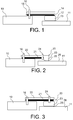
- FIG. figure 1 A first known example of making a contact-type electrical contact between a first part 10 and a second part 11 is illustrated in FIG. figure 1 .
- the electrical contact is made by a contact pad 12 applied on a conductive surface of the second piece 11 along a contact zone 13, metal strips 14 and a flexible rod 15.
- These blades which are connected to a mechanical joint element 16 and electrical to the first piece 10 ensure the passage of the current between the contact pad 12 and the element 16.
- the flexible rod 15 provides a spring function and allows to achieve the contact force without ensuring electrical current flow.
- a second known example of producing a contact-type electrical contact consists of a monoblock contact whose three functions of electrical contact, electrical current flow and spring described above are made in one element obtained for example by machining or stamping.
- This second example constitutes an economic embodiment.
- a difficulty remains because of the joint dimensioning of the current flow function and the spring function.
- the current flow function involves a choice of materials having satisfactory conductive properties to limit heating: typically copper, aluminum or their alloys. But the use of such materials to ensure the spring function causes significant limits on the contact dimensions, especially because of the constraints and the resulting effort, in particular because of a maximum stress not to be exceeded in the material . It follows that for a given size, this second example has a limit value of nominal current.
- the object of the invention is to modify such a monobloc contact, or design close to such a monobloc contact, to increase the nominal current in a given space.
- US 1,776,138 discloses an electrical contact finger having a movable contact arm having a removable termination at one of its ends, its other end being bent and equipped to take a rotational movement, and a deflection spring.
- US 2,636,955 discloses an electrical box of the type comprising contacts on a cover which mate with corresponding contacts in the box when the cover is closed on the box, and means for receiving a replaceable fuse in the cover.
- the invention relates to a high-current contact-type electrical contact device with a high current between a first part which is conductive and a conductive surface of a second part, this device comprising a flexible rod connected to a first mechanical joining element and to the first piece, a contact portion applied to the conductive surface of the second piece and at least one metal contact blade disposed at a first end between a first end of the shank and the first piece characterized in that the flexible shank is conductive and in that the at least one metal blade is at its second end connected to the second end of the flexible rod with a second mechanical and electrical connection element.
- the first joining element may comprise a screw or a rivet.
- the second joining element may comprise a rivet.
- the second joining element can be made by crimping and deformation of a prominent part of a contact pad.
- the first joining element can be connected to the first part by screwing.
- the flexible rod and the contact portion form a single piece.
- the flexible rod and the contact portion are made of copper, aluminum or one of their alloys.
- the device of the invention makes it possible to increase the nominal current for a given size.
- a conductive flexible elongate contact element 20 which is the main conductor of the electric current, provides a spring function and a contact pad function. It can be made in one piece, as illustrated on the figure 2 , or in two pieces, as shown on the figure 3 .
- At least one metal blade 21 forms a complement of section for the passage of electric current so as to obtain a simple structure of the finger in a given size allowing the passage of a maximum nominal current.
- the contact element 20 comprises a first portion 22 in the form of a rod and a second portion 23 in the form of contact pads which can be part of the same part or two separate parts.
- a first end of the at least one blade 21 is disposed between the first part 10 and the first end of the first part of the conductive part 20, itself connected to this first part 10 via the joining element 16.
- a second end of the at least one blade 21 is connected to the second end of the first portion 22 of the contact element 20 by a mechanical and electrical connecting element 24.
- the at least one contact blade makes it possible to increase the nominal current without increasing the contact force.
- the reference 25 represents the zone of contact between the second part 23 of the contact element 20 and the conductive surface 26 of the second part 11.
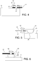
- FIGS. 4 to 6 illustrate exemplary embodiments of the first and second joining members 16 and 24.
- first joining element 16 illustrated in FIG. 4:
- This first joining element 16 can be made using a screw or a rivet 30 connecting the contact element 20 and the contact blade or blades 21 to the first part 10. A single connection then ensures the junction of the three elements: first part 10, metal blades 21 and contact element 20.
- a force distribution washer 31 disposed under the head screw or rivet.
- the second junction of the blade or blades 21 and the contact element 20 can be made either by rivet 40, as shown in FIG. figure 5 , or by crimping and deformation of a prominent part of a contact pad 50 inserted into the blade (s) 21 and the contact element 20, as illustrated on the figure 6 .
- Another effective solution uses a screwing for the two variants considered above. In all cases the same rules as the second point concerning the first connecting element with the first part apply.
- the contact element 20 may have a length of between 3 and 15 cm, a thickness in its first portion 22 of between 3 and 20 mm.
- Each metal blade may have a thickness of between 0.1 mm and 1 mm.
- the contact element 20 and the blades may be made of copper, aluminum or one of their alloys.
Landscapes
- Contacts (AREA)
- Arc-Extinguishing Devices That Are Switches (AREA)
- Conductive Materials (AREA)
Claims (6)
- Elektrische Kontaktvorrichtung vom Typ Kontaktfinger mit starkem elektrischen Nominalstrom zwischen einem ersten Bauteil, das leitend ist (10), und einer leitenden Oberfläche (26) eines zweiten Bauteils (11), wobei diese Vorrichtung eine flexible Stange (22) umfasst, die mit einem ersten Element zur mechanischen und elektrischen Verbindung mit dem ersten Bauteil (10) verbunden ist, ferner ein Kontaktteil (12), das an der leitenden Oberfläche des zweiten Bauteils (11) angebracht ist, sowie wenigstens eine metallische Kontaktzunge (21), die an einem ersten Ende zwischen einem ersten Ende der flexiblen Stange (22) und dem ersten Bauteil (10) angeordnet ist, wobei die flexible Stange (22) leitend ist, und wobei die wenigstens eine Metallzunge (21) an ihrem zweiten Ende mit dem zweiten Ende der flexiblen Stange (22) mit Hilfe eines zweiten mechanischen und elektrischen Verbindungselements (24) derart verbunden ist, dass ein zusätzlicher Querschnitt gebildet wird, der den Durchtritt eines starken elektrischen Nominalstroms erlaubt, und dadurch gekennzeichnet, dass die flexible Stange (22) und das Kontaktteil (23) ein einziges Bauteil bilden.
- Vorrichtung nach Anspruch 1, bei der das erste Verbindungselement (16) eine Schraube oder einen Niet umfasst.
- Vorrichtung nach Anspruch 1, bei der das zweite Verbindungselement (24) einen Niet umfasst.
- Vorrichtung nach Anspruch 1, bei der das zweite Verbindungselement (24) durch Krimpen und Verformen eines vorspringenden Teils eines Kontaktpunkts (50) realisiert ist.
- Vorrichtung nach einem der Ansprüche 3 und 4, bei der das erste Verbindungselement (16) durch Verschrauben mit dem ersten Bauteil (10) verbunden ist.
- Vorrichtung nach Anspruch 1, bei der die flexible Stange und das Kontaktteil aus Kupfer, aus Aluminium oder aus einer ihrer Legierungen hergestellt sind.
Applications Claiming Priority (2)
| Application Number | Priority Date | Filing Date | Title |
|---|---|---|---|
| FR1259334A FR2996352B1 (fr) | 2012-10-02 | 2012-10-02 | Dispositif de contact electrique de type doigt de contact a fort courant nominal |
| PCT/EP2013/070318 WO2014053429A1 (fr) | 2012-10-02 | 2013-09-30 | Dispositif de contact électrique de type doigt de contact a fort courant nominal |
Publications (2)
| Publication Number | Publication Date |
|---|---|
| EP2904623A1 EP2904623A1 (de) | 2015-08-12 |
| EP2904623B1 true EP2904623B1 (de) | 2016-07-13 |
Family
ID=47257998
Family Applications (1)
| Application Number | Title | Priority Date | Filing Date |
|---|---|---|---|
| EP13767003.0A Active EP2904623B1 (de) | 2012-10-02 | 2013-09-30 | Elektrische kontaktvorrichtung in form eines kontaktfingers mit starkem nennstrom |
Country Status (6)
| Country | Link |
|---|---|
| US (1) | US9443666B2 (de) |
| EP (1) | EP2904623B1 (de) |
| JP (1) | JP2015536022A (de) |
| CN (1) | CN104662631B (de) |
| FR (1) | FR2996352B1 (de) |
| WO (1) | WO2014053429A1 (de) |
Family Cites Families (50)
| Publication number | Priority date | Publication date | Assignee | Title |
|---|---|---|---|---|
| US1667652A (en) * | 1925-04-22 | 1928-04-24 | Gen Electric | Contact finger |
| FR626013A (fr) * | 1927-09-07 | 1927-08-25 | Thomson Houston Comp Francaise | Perfectionnements apportés aux contacts électriques |
| US1896560A (en) * | 1931-04-15 | 1933-02-07 | Russell Mfg Co | Contact finger for electrical controllers and switches |
| US2008927A (en) * | 1931-06-17 | 1935-07-23 | Roslyn V H Russell | Removable contact tip |
| DE893684C (de) | 1939-10-11 | 1953-10-19 | Sachsenwerk Licht & Kraft Ag | Antriebsvorrichtung fuer Hochspannungsunterbrecher |
| US2636955A (en) * | 1951-02-14 | 1953-04-28 | Stephen A George Company | Electrical switch box |
| CH425949A (de) | 1965-09-06 | 1966-12-15 | Bbc Brown Boveri & Cie | Druckgasschalter mit Mehrfachunterbrechung |
| US3590186A (en) | 1968-12-19 | 1971-06-29 | Allis Chalmers Mfg Co | Vacuum interrupter having series connected resistor and shunting means for the latter |
| US3778573A (en) | 1972-06-23 | 1973-12-11 | Westinghouse Electric Corp | Vacuum circuit interrupter having improved contact structure |
| US3943314A (en) | 1974-05-14 | 1976-03-09 | Westinghouse Electric Corporation | Motion-multiplying linkage-mechanism for sealed-casing structures |
| US3970809A (en) | 1975-02-10 | 1976-07-20 | General Electric Company | Electric circuit breaker comprising parallel-connected vacuum interrupters |
| US3984651A (en) | 1975-05-01 | 1976-10-05 | Mcgraw-Edison Company | Electrical loadbreak arc quenching and containing assembly |
| JPS56152125A (en) | 1980-04-25 | 1981-11-25 | Tokyo Shibaura Electric Co | Breaker |
| JPS6155829A (ja) | 1984-08-28 | 1986-03-20 | 株式会社東芝 | しや断器 |
| DE3611270C2 (de) | 1986-04-04 | 1995-08-17 | Sachsenwerk Ag | Elektrische Schalteinrichtung für hohe Schaltspannungen |
| US4849589A (en) * | 1987-08-31 | 1989-07-18 | Square D Company | Contact assembly for a circuit breaker |
| JPH01298617A (ja) | 1988-05-27 | 1989-12-01 | Toshiba Corp | 真空バルブ用接点とその製造方法 |
| JPH0719504B2 (ja) | 1988-11-08 | 1995-03-06 | 三菱電機株式会社 | 断路器 |
| FR2738389B1 (fr) | 1995-08-31 | 1997-10-24 | Schneider Electric Sa | Disjoncteur hybrique a haute tension |
| FR2745947B1 (fr) | 1996-03-11 | 1998-04-10 | Gec Alsthom T & D Sa | Disjoncteur a autocompression reduite |
| FR2763171B1 (fr) | 1997-05-07 | 1999-07-09 | Gec Alsthom T & D Sa | Disjoncteur avec sectionneur |
| FR2763422B1 (fr) | 1997-05-15 | 1999-07-09 | Gec Alsthom T & D Sa | Disjoncteur de generateur |
| FR2770678B1 (fr) | 1997-10-30 | 1999-12-31 | Gec Alsthom T & D Sa | Disjoncteur de generateur a commande mecanique unique |
| IT1301872B1 (it) | 1998-07-24 | 2000-07-07 | Abb Adda S P A | Dispositivo di comando e controllo di interruttori di alta e mediatensione |
| DE19837945A1 (de) | 1998-08-21 | 2000-02-24 | Asea Brown Boveri | Schaltanordnung und Verfahren zu ihrer Herstellung |
| JP3664899B2 (ja) | 1998-11-27 | 2005-06-29 | 株式会社東芝 | 真空開閉装置 |
| FR2800905B1 (fr) | 1999-11-08 | 2001-11-30 | Alstom | Interrupteur de centrale avec un echangeur-radiateur |
| JP3799924B2 (ja) | 2000-01-11 | 2006-07-19 | 株式会社日立製作所 | 電力用遮断器および発電所電気回路装置 |
| DE10016950A1 (de) | 2000-04-05 | 2001-10-11 | Abb Hochspannungstechnik Ag Zu | Verfahren zum Abschalten eines Kurzschlussstroms im generatornahen Bereich |
| AU763276B2 (en) | 2001-02-07 | 2003-07-17 | Hitachi Limited | Gas insulated switchgear |
| FR2826503B1 (fr) | 2001-06-25 | 2003-09-05 | Alstom | Chambre de coupure avec ampoule a vide |
| EP1310970B1 (de) | 2001-11-09 | 2007-08-01 | ABB Schweiz AG | Hybridleistungsschalter mit einem Getriebe |
| US6881917B2 (en) | 2002-04-16 | 2005-04-19 | Hitachi, Ltd. | Vacuum switchgear |
| FR2840729B1 (fr) | 2002-06-05 | 2004-07-16 | Alstom | Dispositif interrupteur pour haute ou moyenne tension, a coupure mixte par vide et gaz |
| DE10344652A1 (de) * | 2003-09-25 | 2005-04-28 | Siemens Ag | Niederspannungs-Leistungsschalter mit radialer Kontaktbewegung durch Integration der Kontaktträger in die Schaltwelle |
| ES2654037T3 (es) | 2003-12-02 | 2018-02-12 | Schneider Electric Energy Manufacturing Italia S.R.L. | Dispositivo seccionador/disyuntor para subestaciones eléctricas |
| FR2868199B1 (fr) | 2004-03-25 | 2006-05-19 | Areva T & D Sa | Disjoncteur hybride a haute tension. |
| FR2877136B1 (fr) | 2004-10-27 | 2006-12-15 | Areva T & D Sa | Cinematique d'entrainement dans un disjoncteur hybride |
| JP4498181B2 (ja) * | 2005-03-22 | 2010-07-07 | 東京エレクトロン株式会社 | スイッチアレイ |
| FR2896336B1 (fr) | 2006-01-17 | 2009-04-03 | Areva T & D Sa | Disjoncteur sectionneur d'alternateur de structure compacte |
| FR2896335B1 (fr) | 2006-01-17 | 2008-11-14 | Areva T & D Sa | Disjoncteur de generateur avec resistance inseree |
| FR2901055B1 (fr) | 2006-05-12 | 2008-07-04 | Areva T & D Sa | Disjoncteur sectionneur d'alternateur actionne par un servo-moteur |
| FR2902923B1 (fr) | 2006-06-23 | 2008-09-19 | Areva T & D Sa | Actionnement par came cylindrique d'un disjoncteur sectionneur d'alternateur |
| JP4586849B2 (ja) * | 2007-12-14 | 2010-11-24 | パナソニック電工株式会社 | 電磁リレー |
| FR2951856A1 (fr) | 2009-10-26 | 2011-04-29 | Areva T & D Sas | Procede et dispositif de refroidissement d'une installation electrique moyenne tension sous gaine |
| FR2951857B1 (fr) | 2009-10-26 | 2011-12-23 | Areva T & D Sas | Dispositif de refroidissement d'un appareil moyenne tension utilisant des caloducs sous tension |
| FR2951859B1 (fr) | 2009-10-26 | 2012-12-21 | Areva T & D Sas | Procede de refroidissement par caloducs integres d'un appareil electrique moyenne tension et systeme utilisant ce procede |
| FR2951858B1 (fr) | 2009-10-26 | 2011-12-23 | Areva T & D Sas | Dispositif de refroidissement d'un appareil moyenne tension utilisant des caloducs isoles |
| CN201788835U (zh) * | 2010-03-16 | 2011-04-06 | 黄道铭 | 六脚开关接触桥 |
| FR2985081B1 (fr) | 2011-12-21 | 2015-03-06 | Alstom Technology Ltd | Dispositif de protection contre les particules engendrees par un arc electrique de commutation |
-
2012
- 2012-10-02 FR FR1259334A patent/FR2996352B1/fr active Active
-
2013
- 2013-09-30 EP EP13767003.0A patent/EP2904623B1/de active Active
- 2013-09-30 US US14/429,761 patent/US9443666B2/en active Active
- 2013-09-30 CN CN201380049770.9A patent/CN104662631B/zh active Active
- 2013-09-30 JP JP2015533623A patent/JP2015536022A/ja active Pending
- 2013-09-30 WO PCT/EP2013/070318 patent/WO2014053429A1/fr not_active Ceased
Also Published As
| Publication number | Publication date |
|---|---|
| FR2996352A1 (fr) | 2014-04-04 |
| CN104662631A (zh) | 2015-05-27 |
| FR2996352B1 (fr) | 2014-10-31 |
| CN104662631B (zh) | 2017-08-08 |
| US20150235781A1 (en) | 2015-08-20 |
| WO2014053429A1 (fr) | 2014-04-10 |
| JP2015536022A (ja) | 2015-12-17 |
| US9443666B2 (en) | 2016-09-13 |
| EP2904623A1 (de) | 2015-08-12 |
Similar Documents
| Publication | Publication Date | Title |
|---|---|---|
| EP2725660B1 (de) | Elastisches Gehäuse für Anschlussklemme | |
| EP1653574B1 (de) | Verfahren zur Montage eines elektrischen Verbinders auf ein Koaxialkabel und einen solchen Verbinder | |
| US20140099803A1 (en) | Electrical contact assembly | |
| EP0148051A1 (de) | Verfahren und Einrichtung zum festen elektrischen Verbinden von Litzen auf Stromzufuhrflächen | |
| WO1980002775A1 (fr) | Dispositif de raccordement de conducteurs electriques isoles | |
| FR2828760A1 (fr) | Ensemble a lames pour disjoncteur, et procede d'interruption de circuit | |
| EP2904623B1 (de) | Elektrische kontaktvorrichtung in form eines kontaktfingers mit starkem nennstrom | |
| EP1568109B1 (de) | Elektrischer Kontakt mit elastischer Rückstellvorrichtung und elektrischer Verbindungsteil mit mindestens einem solchen Kontakt | |
| CA1207844A (fr) | Unite de soudage electrique par resistance du type ciseaux | |
| EP2846412A1 (de) | Elektrischer Steckverbinder mit geringem Steckkraftaufwand | |
| EP1933425B1 (de) | Gesicherter elektrischer Kontakt | |
| EP3350884B1 (de) | Elektrischer kontakt und steckbuchse mit solch einem elektrischen kontakt | |
| EP2335318B1 (de) | Durch autogenes nieten erhaltene elektrische/mechanische baugruppe | |
| EP3190664B1 (de) | Elektrogerät mit anschlussklemme, die mit einem klemmkäfig aus nicht-magnetischem material ausgestattet ist | |
| EP0304365B1 (de) | Verbindungsvorrichtung, versehen mit Abschirmungsscheiben für Mikrowellenelemente | |
| EP3109943B1 (de) | Elektrische verbindungsvorrichtung für eine elektrogerät | |
| FR3077166A1 (fr) | Connecteur electrique a lames conductrices et procede correspondant | |
| FR3028356A1 (fr) | Borne de connexion electrique a vis imperdable | |
| WO2020120660A1 (fr) | Barre conductrice, rotor et machine électrique tournante associés | |
| FR2816764A1 (fr) | Dispositif de raccordement pour deux cables electriques | |
| EP2518746B1 (de) | Elektrische Kontaktvorrichtung mit leistungsfähiger Unterbrechung | |
| FR2882196A1 (fr) | Cosse de liaisons electriques | |
| EP3082194A1 (de) | Elektrische anschlussklemme zur aufnahme eines messers | |
| BE742819A (de) | ||
| FR2852729A1 (fr) | Appareil electrique ou moyenne tension comprenant une bande de contacts a lamelles |
Legal Events
| Date | Code | Title | Description |
|---|---|---|---|
| PUAI | Public reference made under article 153(3) epc to a published international application that has entered the european phase |
Free format text: ORIGINAL CODE: 0009012 |
|
| 17P | Request for examination filed |
Effective date: 20150403 |
|
| AK | Designated contracting states |
Kind code of ref document: A1 Designated state(s): AL AT BE BG CH CY CZ DE DK EE ES FI FR GB GR HR HU IE IS IT LI LT LU LV MC MK MT NL NO PL PT RO RS SE SI SK SM TR |
|
| AX | Request for extension of the european patent |
Extension state: BA ME |
|
| DAX | Request for extension of the european patent (deleted) | ||
| GRAP | Despatch of communication of intention to grant a patent |
Free format text: ORIGINAL CODE: EPIDOSNIGR1 |
|
| INTG | Intention to grant announced |
Effective date: 20160203 |
|
| RAP1 | Party data changed (applicant data changed or rights of an application transferred) |
Owner name: GENERAL ELECTRIC TECHNOLOGY GMBH |
|
| GRAS | Grant fee paid |
Free format text: ORIGINAL CODE: EPIDOSNIGR3 |
|
| GRAA | (expected) grant |
Free format text: ORIGINAL CODE: 0009210 |
|
| AK | Designated contracting states |
Kind code of ref document: B1 Designated state(s): AL AT BE BG CH CY CZ DE DK EE ES FI FR GB GR HR HU IE IS IT LI LT LU LV MC MK MT NL NO PL PT RO RS SE SI SK SM TR |
|
| REG | Reference to a national code |
Ref country code: GB Ref legal event code: FG4D Free format text: NOT ENGLISH |
|
| REG | Reference to a national code |
Ref country code: AT Ref legal event code: REF Ref document number: 812898 Country of ref document: AT Kind code of ref document: T Effective date: 20160715 Ref country code: CH Ref legal event code: EP |
|
| REG | Reference to a national code |
Ref country code: IE Ref legal event code: FG4D Free format text: LANGUAGE OF EP DOCUMENT: FRENCH |
|
| REG | Reference to a national code |
Ref country code: DE Ref legal event code: R096 Ref document number: 602013009434 Country of ref document: DE |
|
| REG | Reference to a national code |
Ref country code: CH Ref legal event code: NV Representative=s name: BOVARD AG, CH |
|
| REG | Reference to a national code |
Ref country code: FR Ref legal event code: PLFP Year of fee payment: 4 |
|
| REG | Reference to a national code |
Ref country code: LT Ref legal event code: MG4D |
|
| REG | Reference to a national code |
Ref country code: NL Ref legal event code: MP Effective date: 20160713 |
|
| REG | Reference to a national code |
Ref country code: AT Ref legal event code: MK05 Ref document number: 812898 Country of ref document: AT Kind code of ref document: T Effective date: 20160713 |
|
| PG25 | Lapsed in a contracting state [announced via postgrant information from national office to epo] |
Ref country code: HR Free format text: LAPSE BECAUSE OF FAILURE TO SUBMIT A TRANSLATION OF THE DESCRIPTION OR TO PAY THE FEE WITHIN THE PRESCRIBED TIME-LIMIT Effective date: 20160713 Ref country code: IS Free format text: LAPSE BECAUSE OF FAILURE TO SUBMIT A TRANSLATION OF THE DESCRIPTION OR TO PAY THE FEE WITHIN THE PRESCRIBED TIME-LIMIT Effective date: 20161113 Ref country code: RS Free format text: LAPSE BECAUSE OF FAILURE TO SUBMIT A TRANSLATION OF THE DESCRIPTION OR TO PAY THE FEE WITHIN THE PRESCRIBED TIME-LIMIT Effective date: 20160713 Ref country code: NO Free format text: LAPSE BECAUSE OF FAILURE TO SUBMIT A TRANSLATION OF THE DESCRIPTION OR TO PAY THE FEE WITHIN THE PRESCRIBED TIME-LIMIT Effective date: 20161013 Ref country code: LT Free format text: LAPSE BECAUSE OF FAILURE TO SUBMIT A TRANSLATION OF THE DESCRIPTION OR TO PAY THE FEE WITHIN THE PRESCRIBED TIME-LIMIT Effective date: 20160713 Ref country code: NL Free format text: LAPSE BECAUSE OF FAILURE TO SUBMIT A TRANSLATION OF THE DESCRIPTION OR TO PAY THE FEE WITHIN THE PRESCRIBED TIME-LIMIT Effective date: 20160713 Ref country code: FI Free format text: LAPSE BECAUSE OF FAILURE TO SUBMIT A TRANSLATION OF THE DESCRIPTION OR TO PAY THE FEE WITHIN THE PRESCRIBED TIME-LIMIT Effective date: 20160713 Ref country code: IT Free format text: LAPSE BECAUSE OF FAILURE TO SUBMIT A TRANSLATION OF THE DESCRIPTION OR TO PAY THE FEE WITHIN THE PRESCRIBED TIME-LIMIT Effective date: 20160713 |
|
| PG25 | Lapsed in a contracting state [announced via postgrant information from national office to epo] |
Ref country code: AT Free format text: LAPSE BECAUSE OF FAILURE TO SUBMIT A TRANSLATION OF THE DESCRIPTION OR TO PAY THE FEE WITHIN THE PRESCRIBED TIME-LIMIT Effective date: 20160713 Ref country code: PT Free format text: LAPSE BECAUSE OF FAILURE TO SUBMIT A TRANSLATION OF THE DESCRIPTION OR TO PAY THE FEE WITHIN THE PRESCRIBED TIME-LIMIT Effective date: 20161114 Ref country code: SE Free format text: LAPSE BECAUSE OF FAILURE TO SUBMIT A TRANSLATION OF THE DESCRIPTION OR TO PAY THE FEE WITHIN THE PRESCRIBED TIME-LIMIT Effective date: 20160713 Ref country code: BE Free format text: LAPSE BECAUSE OF NON-PAYMENT OF DUE FEES Effective date: 20160930 Ref country code: LV Free format text: LAPSE BECAUSE OF FAILURE TO SUBMIT A TRANSLATION OF THE DESCRIPTION OR TO PAY THE FEE WITHIN THE PRESCRIBED TIME-LIMIT Effective date: 20160713 Ref country code: PL Free format text: LAPSE BECAUSE OF FAILURE TO SUBMIT A TRANSLATION OF THE DESCRIPTION OR TO PAY THE FEE WITHIN THE PRESCRIBED TIME-LIMIT Effective date: 20160713 Ref country code: ES Free format text: LAPSE BECAUSE OF FAILURE TO SUBMIT A TRANSLATION OF THE DESCRIPTION OR TO PAY THE FEE WITHIN THE PRESCRIBED TIME-LIMIT Effective date: 20160713 Ref country code: GR Free format text: LAPSE BECAUSE OF FAILURE TO SUBMIT A TRANSLATION OF THE DESCRIPTION OR TO PAY THE FEE WITHIN THE PRESCRIBED TIME-LIMIT Effective date: 20161014 |
|
| REG | Reference to a national code |
Ref country code: DE Ref legal event code: R097 Ref document number: 602013009434 Country of ref document: DE |
|
| PG25 | Lapsed in a contracting state [announced via postgrant information from national office to epo] |
Ref country code: EE Free format text: LAPSE BECAUSE OF FAILURE TO SUBMIT A TRANSLATION OF THE DESCRIPTION OR TO PAY THE FEE WITHIN THE PRESCRIBED TIME-LIMIT Effective date: 20160713 Ref country code: MC Free format text: LAPSE BECAUSE OF FAILURE TO SUBMIT A TRANSLATION OF THE DESCRIPTION OR TO PAY THE FEE WITHIN THE PRESCRIBED TIME-LIMIT Effective date: 20160713 Ref country code: RO Free format text: LAPSE BECAUSE OF FAILURE TO SUBMIT A TRANSLATION OF THE DESCRIPTION OR TO PAY THE FEE WITHIN THE PRESCRIBED TIME-LIMIT Effective date: 20160713 |
|
| PLBE | No opposition filed within time limit |
Free format text: ORIGINAL CODE: 0009261 |
|
| STAA | Information on the status of an ep patent application or granted ep patent |
Free format text: STATUS: NO OPPOSITION FILED WITHIN TIME LIMIT |
|
| PG25 | Lapsed in a contracting state [announced via postgrant information from national office to epo] |
Ref country code: DK Free format text: LAPSE BECAUSE OF FAILURE TO SUBMIT A TRANSLATION OF THE DESCRIPTION OR TO PAY THE FEE WITHIN THE PRESCRIBED TIME-LIMIT Effective date: 20160713 Ref country code: SM Free format text: LAPSE BECAUSE OF FAILURE TO SUBMIT A TRANSLATION OF THE DESCRIPTION OR TO PAY THE FEE WITHIN THE PRESCRIBED TIME-LIMIT Effective date: 20160713 Ref country code: CZ Free format text: LAPSE BECAUSE OF FAILURE TO SUBMIT A TRANSLATION OF THE DESCRIPTION OR TO PAY THE FEE WITHIN THE PRESCRIBED TIME-LIMIT Effective date: 20160713 Ref country code: SK Free format text: LAPSE BECAUSE OF FAILURE TO SUBMIT A TRANSLATION OF THE DESCRIPTION OR TO PAY THE FEE WITHIN THE PRESCRIBED TIME-LIMIT Effective date: 20160713 Ref country code: BG Free format text: LAPSE BECAUSE OF FAILURE TO SUBMIT A TRANSLATION OF THE DESCRIPTION OR TO PAY THE FEE WITHIN THE PRESCRIBED TIME-LIMIT Effective date: 20161013 |
|
| 26N | No opposition filed |
Effective date: 20170418 |
|
| REG | Reference to a national code |
Ref country code: IE Ref legal event code: MM4A |
|
| PG25 | Lapsed in a contracting state [announced via postgrant information from national office to epo] |
Ref country code: IE Free format text: LAPSE BECAUSE OF NON-PAYMENT OF DUE FEES Effective date: 20160930 |
|
| PG25 | Lapsed in a contracting state [announced via postgrant information from national office to epo] |
Ref country code: SI Free format text: LAPSE BECAUSE OF FAILURE TO SUBMIT A TRANSLATION OF THE DESCRIPTION OR TO PAY THE FEE WITHIN THE PRESCRIBED TIME-LIMIT Effective date: 20160713 Ref country code: LU Free format text: LAPSE BECAUSE OF NON-PAYMENT OF DUE FEES Effective date: 20160930 |
|
| REG | Reference to a national code |
Ref country code: FR Ref legal event code: PLFP Year of fee payment: 5 |
|
| PGFP | Annual fee paid to national office [announced via postgrant information from national office to epo] |
Ref country code: FR Payment date: 20170925 Year of fee payment: 5 |
|
| REG | Reference to a national code |
Ref country code: BE Ref legal event code: MM Effective date: 20160930 |
|
| GBPC | Gb: european patent ceased through non-payment of renewal fee |
Effective date: 20170930 |
|
| PG25 | Lapsed in a contracting state [announced via postgrant information from national office to epo] |
Ref country code: HU Free format text: LAPSE BECAUSE OF FAILURE TO SUBMIT A TRANSLATION OF THE DESCRIPTION OR TO PAY THE FEE WITHIN THE PRESCRIBED TIME-LIMIT; INVALID AB INITIO Effective date: 20130930 |
|
| PG25 | Lapsed in a contracting state [announced via postgrant information from national office to epo] |
Ref country code: MK Free format text: LAPSE BECAUSE OF FAILURE TO SUBMIT A TRANSLATION OF THE DESCRIPTION OR TO PAY THE FEE WITHIN THE PRESCRIBED TIME-LIMIT Effective date: 20160713 Ref country code: CY Free format text: LAPSE BECAUSE OF FAILURE TO SUBMIT A TRANSLATION OF THE DESCRIPTION OR TO PAY THE FEE WITHIN THE PRESCRIBED TIME-LIMIT Effective date: 20160713 Ref country code: MT Free format text: LAPSE BECAUSE OF FAILURE TO SUBMIT A TRANSLATION OF THE DESCRIPTION OR TO PAY THE FEE WITHIN THE PRESCRIBED TIME-LIMIT Effective date: 20160713 |
|
| PG25 | Lapsed in a contracting state [announced via postgrant information from national office to epo] |
Ref country code: GB Free format text: LAPSE BECAUSE OF NON-PAYMENT OF DUE FEES Effective date: 20170930 |
|
| PG25 | Lapsed in a contracting state [announced via postgrant information from national office to epo] |
Ref country code: TR Free format text: LAPSE BECAUSE OF FAILURE TO SUBMIT A TRANSLATION OF THE DESCRIPTION OR TO PAY THE FEE WITHIN THE PRESCRIBED TIME-LIMIT Effective date: 20160713 Ref country code: AL Free format text: LAPSE BECAUSE OF FAILURE TO SUBMIT A TRANSLATION OF THE DESCRIPTION OR TO PAY THE FEE WITHIN THE PRESCRIBED TIME-LIMIT Effective date: 20160713 |
|
| PG25 | Lapsed in a contracting state [announced via postgrant information from national office to epo] |
Ref country code: FR Free format text: LAPSE BECAUSE OF NON-PAYMENT OF DUE FEES Effective date: 20180930 |
|
| P01 | Opt-out of the competence of the unified patent court (upc) registered |
Effective date: 20230522 |
|
| REG | Reference to a national code |
Ref country code: CH Ref legal event code: U11 Free format text: ST27 STATUS EVENT CODE: U-0-0-U10-U11 (AS PROVIDED BY THE NATIONAL OFFICE) Effective date: 20251001 |
|
| PGFP | Annual fee paid to national office [announced via postgrant information from national office to epo] |
Ref country code: DE Payment date: 20250820 Year of fee payment: 13 |
|
| PGFP | Annual fee paid to national office [announced via postgrant information from national office to epo] |
Ref country code: CH Payment date: 20251001 Year of fee payment: 13 |