EP2905104A2 - Procédé de monitorage optique de la surface dans le domaine de l'action du rayonnement laser et dispositif pour sa mise en oeuvre - Google Patents
Procédé de monitorage optique de la surface dans le domaine de l'action du rayonnement laser et dispositif pour sa mise en oeuvre Download PDFInfo
- Publication number
- EP2905104A2 EP2905104A2 EP12831885.4A EP12831885A EP2905104A2 EP 2905104 A2 EP2905104 A2 EP 2905104A2 EP 12831885 A EP12831885 A EP 12831885A EP 2905104 A2 EP2905104 A2 EP 2905104A2
- Authority
- EP
- European Patent Office
- Prior art keywords
- laser
- radiation
- spectral
- area
- mirror
- Prior art date
- Legal status (The legal status is an assumption and is not a legal conclusion. Google has not performed a legal analysis and makes no representation as to the accuracy of the status listed.)
- Withdrawn
Links
Images


Classifications
-
- B—PERFORMING OPERATIONS; TRANSPORTING
- B23—MACHINE TOOLS; METAL-WORKING NOT OTHERWISE PROVIDED FOR
- B23K—SOLDERING OR UNSOLDERING; WELDING; CLADDING OR PLATING BY SOLDERING OR WELDING; CUTTING BY APPLYING HEAT LOCALLY, e.g. FLAME CUTTING; WORKING BY LASER BEAM
- B23K26/00—Working by laser beam, e.g. welding, cutting or boring
- B23K26/02—Positioning or observing the workpiece, e.g. with respect to the point of impact; Aligning, aiming or focusing the laser beam
- B23K26/03—Observing, e.g. monitoring, the workpiece
- B23K26/034—Observing the temperature of the workpiece
-
- G—PHYSICS
- G01—MEASURING; TESTING
- G01J—MEASUREMENT OF INTENSITY, VELOCITY, SPECTRAL CONTENT, POLARISATION, PHASE OR PULSE CHARACTERISTICS OF INFRARED, VISIBLE OR ULTRAVIOLET LIGHT; COLORIMETRY; RADIATION PYROMETRY
- G01J5/00—Radiation pyrometry, e.g. infrared or optical thermometry
- G01J5/02—Constructional details
- G01J5/08—Optical arrangements
- G01J5/0813—Planar mirrors; Parallel phase plates
-
- B—PERFORMING OPERATIONS; TRANSPORTING
- B23—MACHINE TOOLS; METAL-WORKING NOT OTHERWISE PROVIDED FOR
- B23K—SOLDERING OR UNSOLDERING; WELDING; CLADDING OR PLATING BY SOLDERING OR WELDING; CUTTING BY APPLYING HEAT LOCALLY, e.g. FLAME CUTTING; WORKING BY LASER BEAM
- B23K26/00—Working by laser beam, e.g. welding, cutting or boring
- B23K26/02—Positioning or observing the workpiece, e.g. with respect to the point of impact; Aligning, aiming or focusing the laser beam
-
- B—PERFORMING OPERATIONS; TRANSPORTING
- B23—MACHINE TOOLS; METAL-WORKING NOT OTHERWISE PROVIDED FOR
- B23K—SOLDERING OR UNSOLDERING; WELDING; CLADDING OR PLATING BY SOLDERING OR WELDING; CUTTING BY APPLYING HEAT LOCALLY, e.g. FLAME CUTTING; WORKING BY LASER BEAM
- B23K26/00—Working by laser beam, e.g. welding, cutting or boring
- B23K26/02—Positioning or observing the workpiece, e.g. with respect to the point of impact; Aligning, aiming or focusing the laser beam
- B23K26/03—Observing, e.g. monitoring, the workpiece
- B23K26/032—Observing, e.g. monitoring, the workpiece using optical means
-
- B—PERFORMING OPERATIONS; TRANSPORTING
- B23—MACHINE TOOLS; METAL-WORKING NOT OTHERWISE PROVIDED FOR
- B23K—SOLDERING OR UNSOLDERING; WELDING; CLADDING OR PLATING BY SOLDERING OR WELDING; CUTTING BY APPLYING HEAT LOCALLY, e.g. FLAME CUTTING; WORKING BY LASER BEAM
- B23K26/00—Working by laser beam, e.g. welding, cutting or boring
- B23K26/02—Positioning or observing the workpiece, e.g. with respect to the point of impact; Aligning, aiming or focusing the laser beam
- B23K26/06—Shaping the laser beam, e.g. by masks or multi-focusing
- B23K26/064—Shaping the laser beam, e.g. by masks or multi-focusing by means of optical elements, e.g. lenses, mirrors or prisms
- B23K26/0648—Shaping the laser beam, e.g. by masks or multi-focusing by means of optical elements, e.g. lenses, mirrors or prisms comprising lenses
-
- B—PERFORMING OPERATIONS; TRANSPORTING
- B23—MACHINE TOOLS; METAL-WORKING NOT OTHERWISE PROVIDED FOR
- B23K—SOLDERING OR UNSOLDERING; WELDING; CLADDING OR PLATING BY SOLDERING OR WELDING; CUTTING BY APPLYING HEAT LOCALLY, e.g. FLAME CUTTING; WORKING BY LASER BEAM
- B23K26/00—Working by laser beam, e.g. welding, cutting or boring
- B23K26/08—Devices involving relative movement between laser beam and workpiece
- B23K26/082—Scanning systems, i.e. devices involving movement of the laser beam relative to the laser head
-
- G—PHYSICS
- G01—MEASURING; TESTING
- G01J—MEASUREMENT OF INTENSITY, VELOCITY, SPECTRAL CONTENT, POLARISATION, PHASE OR PULSE CHARACTERISTICS OF INFRARED, VISIBLE OR ULTRAVIOLET LIGHT; COLORIMETRY; RADIATION PYROMETRY
- G01J5/00—Radiation pyrometry, e.g. infrared or optical thermometry
- G01J5/0014—Radiation pyrometry, e.g. infrared or optical thermometry for sensing the radiation from gases, flames
- G01J5/0018—Flames, plasma or welding
-
- G—PHYSICS
- G01—MEASURING; TESTING
- G01J—MEASUREMENT OF INTENSITY, VELOCITY, SPECTRAL CONTENT, POLARISATION, PHASE OR PULSE CHARACTERISTICS OF INFRARED, VISIBLE OR ULTRAVIOLET LIGHT; COLORIMETRY; RADIATION PYROMETRY
- G01J5/00—Radiation pyrometry, e.g. infrared or optical thermometry
- G01J5/02—Constructional details
- G01J5/025—Interfacing a pyrometer to an external device or network; User interface
-
- G—PHYSICS
- G01—MEASURING; TESTING
- G01J—MEASUREMENT OF INTENSITY, VELOCITY, SPECTRAL CONTENT, POLARISATION, PHASE OR PULSE CHARACTERISTICS OF INFRARED, VISIBLE OR ULTRAVIOLET LIGHT; COLORIMETRY; RADIATION PYROMETRY
- G01J5/00—Radiation pyrometry, e.g. infrared or optical thermometry
- G01J5/02—Constructional details
- G01J5/08—Optical arrangements
- G01J5/0806—Focusing or collimating elements, e.g. lenses or concave mirrors
-
- G—PHYSICS
- G01—MEASURING; TESTING
- G01J—MEASUREMENT OF INTENSITY, VELOCITY, SPECTRAL CONTENT, POLARISATION, PHASE OR PULSE CHARACTERISTICS OF INFRARED, VISIBLE OR ULTRAVIOLET LIGHT; COLORIMETRY; RADIATION PYROMETRY
- G01J5/00—Radiation pyrometry, e.g. infrared or optical thermometry
- G01J5/02—Constructional details
- G01J5/08—Optical arrangements
- G01J5/0808—Convex mirrors
-
- G—PHYSICS
- G01—MEASURING; TESTING
- G01J—MEASUREMENT OF INTENSITY, VELOCITY, SPECTRAL CONTENT, POLARISATION, PHASE OR PULSE CHARACTERISTICS OF INFRARED, VISIBLE OR ULTRAVIOLET LIGHT; COLORIMETRY; RADIATION PYROMETRY
- G01J5/00—Radiation pyrometry, e.g. infrared or optical thermometry
- G01J5/02—Constructional details
- G01J5/08—Optical arrangements
- G01J5/0818—Waveguides
- G01J5/0821—Optical fibres
-
- G—PHYSICS
- G01—MEASURING; TESTING
- G01J—MEASUREMENT OF INTENSITY, VELOCITY, SPECTRAL CONTENT, POLARISATION, PHASE OR PULSE CHARACTERISTICS OF INFRARED, VISIBLE OR ULTRAVIOLET LIGHT; COLORIMETRY; RADIATION PYROMETRY
- G01J5/00—Radiation pyrometry, e.g. infrared or optical thermometry
- G01J5/02—Constructional details
- G01J5/08—Optical arrangements
- G01J5/084—Adjustable or slidable
-
- G—PHYSICS
- G01—MEASURING; TESTING
- G01J—MEASUREMENT OF INTENSITY, VELOCITY, SPECTRAL CONTENT, POLARISATION, PHASE OR PULSE CHARACTERISTICS OF INFRARED, VISIBLE OR ULTRAVIOLET LIGHT; COLORIMETRY; RADIATION PYROMETRY
- G01J5/00—Radiation pyrometry, e.g. infrared or optical thermometry
- G01J5/02—Constructional details
- G01J5/08—Optical arrangements
- G01J5/0846—Optical arrangements having multiple detectors for performing different types of detection, e.g. using radiometry and reflectometry channels
-
- G—PHYSICS
- G01—MEASURING; TESTING
- G01J—MEASUREMENT OF INTENSITY, VELOCITY, SPECTRAL CONTENT, POLARISATION, PHASE OR PULSE CHARACTERISTICS OF INFRARED, VISIBLE OR ULTRAVIOLET LIGHT; COLORIMETRY; RADIATION PYROMETRY
- G01J5/00—Radiation pyrometry, e.g. infrared or optical thermometry
- G01J5/02—Constructional details
- G01J5/08—Optical arrangements
- G01J5/0859—Sighting arrangements, e.g. cameras
-
- G—PHYSICS
- G01—MEASURING; TESTING
- G01J—MEASUREMENT OF INTENSITY, VELOCITY, SPECTRAL CONTENT, POLARISATION, PHASE OR PULSE CHARACTERISTICS OF INFRARED, VISIBLE OR ULTRAVIOLET LIGHT; COLORIMETRY; RADIATION PYROMETRY
- G01J5/00—Radiation pyrometry, e.g. infrared or optical thermometry
- G01J5/02—Constructional details
- G01J5/08—Optical arrangements
- G01J5/0871—Beam switching arrangements; Photodetection involving different fields of view for a single detector
-
- G—PHYSICS
- G01—MEASURING; TESTING
- G01J—MEASUREMENT OF INTENSITY, VELOCITY, SPECTRAL CONTENT, POLARISATION, PHASE OR PULSE CHARACTERISTICS OF INFRARED, VISIBLE OR ULTRAVIOLET LIGHT; COLORIMETRY; RADIATION PYROMETRY
- G01J5/00—Radiation pyrometry, e.g. infrared or optical thermometry
- G01J5/02—Constructional details
- G01J5/08—Optical arrangements
- G01J5/0896—Optical arrangements using a light source, e.g. for illuminating a surface
-
- G—PHYSICS
- G01—MEASURING; TESTING
- G01J—MEASUREMENT OF INTENSITY, VELOCITY, SPECTRAL CONTENT, POLARISATION, PHASE OR PULSE CHARACTERISTICS OF INFRARED, VISIBLE OR ULTRAVIOLET LIGHT; COLORIMETRY; RADIATION PYROMETRY
- G01J5/00—Radiation pyrometry, e.g. infrared or optical thermometry
- G01J5/60—Radiation pyrometry, e.g. infrared or optical thermometry using determination of colour temperature
-
- G—PHYSICS
- G01—MEASURING; TESTING
- G01J—MEASUREMENT OF INTENSITY, VELOCITY, SPECTRAL CONTENT, POLARISATION, PHASE OR PULSE CHARACTERISTICS OF INFRARED, VISIBLE OR ULTRAVIOLET LIGHT; COLORIMETRY; RADIATION PYROMETRY
- G01J5/00—Radiation pyrometry, e.g. infrared or optical thermometry
- G01J5/60—Radiation pyrometry, e.g. infrared or optical thermometry using determination of colour temperature
- G01J5/602—Radiation pyrometry, e.g. infrared or optical thermometry using determination of colour temperature using selective, monochromatic or bandpass filtering
Definitions
- the invention relates to the field of measuring technology and can be used in measuring the temperature of a surface in an area thereof subject to laser radiation.
- a method for optical monitoring the surfaces in the laser processing by measuring the temperature [1], consisting in the reception of the thermal radiation from the surface in the two spectral ranges.
- the disadvantage of this method is that it can not be applied to the system with the galvanometer scanner with F-teta lens and a limited level of information.
- the disadvantage of this method is that it can not be applied to the system with the galvanometer scanner with F-teta lens and a limited level of information about sintering process.
- the disadvantage of this method is that registration is performed in the spectral intervals significantly distant from the laser wavelength , which results, when scanning the surface, in a significant shift between the surface image at these wavelengths and image at the laser wavelength due to aberrations of industrial F-teta lens. This results to considerable error in the result of measurement of temperature.
- F-teta lens can be corrected for only one wavelength and multichannel pyrometer measurement can not be performed correctly. Also corrected F-teta lens is very expensive.
- Device for optical monitoring comprising a scanner and a 2- channel optical pyrometer with lens.
- This device does not provide the precision in measuring the temperature of small spots of laser irradiation using a scanner with a F-teta lens due strong chromatic aberration of F-teta lenses at wavelengths distant from the design wavelength - the wavelength of the laser.
- Device for optical monitoring comprising a scanner , a photodiode with lens and videocamera with lens.
- This device does not provide the measuring the temperature of small spots of laser irradiation because only character of photodiode signal is registered. Also it is not possible, using a scanner with a F-teta lens and videocamera for melt pool size measurement , to receive correct results due strong chromatic aberration of F-teta lenses at wavelengths distant from the design wavelength - the wavelength of the laser.
- Device for optical monitoring presented in [3,4] which is closest in technical essence to claimed device.
- Device comprising galvanometer with F-teta lens and 2- channel optical pyrometer with lens ,videocamera with lens.
- the dichroic mirrors swivel may allocate the spectrum of the radiation sent to the pyrometer , only the weak reflection mirrors and distant from the laser wavelength which leads to measurement errors due to shear the image formed by F-teta lens and pyrometer lens at the entrance aperture of the pyrometer. Also images obtained with a video camera distorted due to the strong aberrations of the F-teta lens because the wavelength of the recording of the image is located away from the design wavelength of the lens - the laser wavelength.
- the aim of the claimed invention is to develop a method for optically monitoring a surface in an area thereof subject to laser radiation by scanning the surface using a galvanometer scanner with an F-theta lens, and a device for implementing said method, thereby making it possible to obtain full information about the condition of the surface under the effect of laser radiation.
- the spectral lines of the thermal radiation of the surface recorded with a pyrometer, the spectral bands of the thermal radiation of the surface recorded with a video camera and the spectral lines of the radiation of sources of illumination are situated in the spectral passband of a galvanometer scanner on either side and in the immediate vicinity of the spectral line of the laser radiation.
- the device for optical monitoring additionally comprises a rotary mirror with an elliptical region in the centre having a coating with 100% reflection on the wavelength of the laser, while the peripheral region of the mirror has high transmission in the region of the spectrum outside the emission band of the laser.
- the device for optical monitoring additionally comprises a rotary mirror having a central elliptical aperture with 100% transmission of laser radiation and a broadband reflective coating on the periphery of the mirror.
- the device for optical monitoring additionally comprises a source of illumination of the surface in the area subject to laser treatment, which source is optically connected to the galvanometer scanner and the video camera, wherein the wavelength of the radiation of said source is situated close to the line of radiation of the laser and in the spectral band of reflection of the mirrors of the galvanometer scanner.
- the aim of the claimed invention is to develop a method for optically monitoring a surface in an area thereof subject to laser radiation by scanning the surface using a galvanometer scanner with an F-theta lens allows one to obtain full information on the state of the surface in the area of laser exposure by measuring the maximum surface temperature in the laser irradiation spot, the temperature distribution in the area, the size of molten bath and other structures.
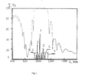
- the essence of the method is explained in Figure 1 .
- the spectral lines 3 of thermal radiation from the surface registered by multichannel pyrometer, spectral lines 4, 5 of the thermal image of the surface registered by the videocamera , and the spectral line of a illumination source 2 lay in the passband of the galvanometer scanner in the immediate vicinity of the laser wavelength 1 . This provides minimal distortion and high accuracy measurement results because of the small aberrations F-teta lens in this wavelength region .
- An apparatus for measuring the surface temperature , its distribution in the laser irradiation area and for obtaining images of the surface
- Device consists of galvanometer scanner with F-teta lens, multichannel optical pyrometer with lens , camera with lens and source of surface illumination.
- a rotary mirrors with variable reflectance over the surface the laser radiation is introduced into the scanner through the mirrors central area with 100% or 0% reflection.
- Thermal radiation of the surface and radiation of the illumination source scattered by the surface are directed to pyrometer and videocamera through the peripheral areas of the mirrors outside the laser line but in its immediate vicinity.
- FIG. 2 The essence of the claimed device is explained in the drawing ( FIG. 2 ), where 1 is a laser, 2 - rotary mirror, 3 - galvanometer scanner, 4 - lens, 5 - the surface being treated , 6 - F-teta lens, dichroic mirror -7, 8 - the diaphragm of pyrometer, 9 - fiber, 10 - pyrometer, 11 - filters, 12 - lens, 13 - videocamera .
- the device operates as follows. Radiation of laser 1 passes through the central area of the rotary mirror and is introduced onto galvanometer scanner mirror 3 and using F-teta lens 6 focuses on the surface 5 . When scanner mirrors rotate laser focus is moved over the surface 5 . Image of the focal region is projected on the diaphragm of the pyrometer 8 with F-teta lens and lens of the pyrometer 4. Pyrometer 10 detects the thermal radiation of the heated surface in narrow spectral regions from small surface area defined by the size of hole of diaphragm.
- lens 12 and F-teta lens image of the surface at a wavelength of filter 11 is recorded by camera 13 .
- the laser light is passed through central elliptical region with 100% transmittance. Since the measurements are made at wavelengths near the line of the laser, the small chromatic aberration of the F-teta lens will lead to negligible shift the image on the diaphragm of the pyrometer and minimal distortion of the image recorded by videocamera occurs.
- Multichannel pyrometer with 3 number of channels allows determine the emissivity of the surface, which allows to get distribution of the thermodynamic temperature.
- the device at Figure 3 has 100 % reflective mirror at laser wavelength at the central region and 100 % passing periphery of the mirror in a wide range.
- the device at Fig.4 additionally includes a illumination source 16 for backlight of the surface whose radiation using a telescope 17 and rotating mirror 18 and mirror 2 is introduced into galvanometer scanner and focuses in the treatment area.
- the surface image at source wavelength is constructed using the F-teta lens and lens 4 in the plane 12 of the matrix of videocamera 13 through the filters 11 which allocates either source radiation or thermal radiation of the surface.
- the claimed method and apparatus provide complete monitoring of the surface in the area of laser irradiation during its scan using galvanometer scanner with F-teta lens with precision and accuracy using standard optics.
Landscapes
- Physics & Mathematics (AREA)
- General Physics & Mathematics (AREA)
- Spectroscopy & Molecular Physics (AREA)
- Optics & Photonics (AREA)
- Engineering & Computer Science (AREA)
- Plasma & Fusion (AREA)
- Mechanical Engineering (AREA)
- Human Computer Interaction (AREA)
- Radiation Pyrometers (AREA)
- Laser Beam Processing (AREA)
Applications Claiming Priority (2)
| Application Number | Priority Date | Filing Date | Title |
|---|---|---|---|
| RU2011137685/28A RU2520944C2 (ru) | 2011-09-13 | 2011-09-13 | Способ оптического мониторинга поверхности в области воздействия лазерного излучения и устройство для его осуществления |
| PCT/IB2012/001793 WO2013038263A2 (fr) | 2011-09-13 | 2012-09-13 | Procédé de monitorage optique de la surface dans le domaine de l'action du rayonnement laser et dispositif pour sa mise en oeuvre |
Publications (2)
| Publication Number | Publication Date |
|---|---|
| EP2905104A2 true EP2905104A2 (fr) | 2015-08-12 |
| EP2905104A4 EP2905104A4 (fr) | 2016-08-10 |
Family
ID=47883855
Family Applications (1)
| Application Number | Title | Priority Date | Filing Date |
|---|---|---|---|
| EP12831885.4A Withdrawn EP2905104A4 (fr) | 2011-09-13 | 2012-09-13 | Procédé de monitorage optique de la surface dans le domaine de l'action du rayonnement laser et dispositif pour sa mise en oeuvre |
Country Status (3)
| Country | Link |
|---|---|
| EP (1) | EP2905104A4 (fr) |
| RU (1) | RU2520944C2 (fr) |
| WO (1) | WO2013038263A2 (fr) |
Cited By (3)
| Publication number | Priority date | Publication date | Assignee | Title |
|---|---|---|---|---|
| WO2017051168A1 (fr) * | 2015-09-21 | 2017-03-30 | Renishaw Plc | Appareil de fabrication additive et module optique destiné à être utilisé dans ledit appareil |
| CN108127206A (zh) * | 2017-12-21 | 2018-06-08 | 武汉比天科技有限责任公司 | 一种激光钎焊工艺移植方法及可移植数据的激光钎焊装置 |
| EP3909706A1 (fr) * | 2020-05-13 | 2021-11-17 | National Chung Shan Institute of Science and Technology | Système d'évaluation d'image de rayonnement thermique coaxial à insert |
Families Citing this family (1)
| Publication number | Priority date | Publication date | Assignee | Title |
|---|---|---|---|---|
| DE102014101576B4 (de) | 2014-02-07 | 2019-10-02 | Dr. Mergenthaler Gmbh & Co. Kg | Vorrichtung zur Bearbeitung von Werkstücken |
Family Cites Families (13)
| Publication number | Priority date | Publication date | Assignee | Title |
|---|---|---|---|---|
| JPS6186636A (ja) * | 1984-10-05 | 1986-05-02 | Kawasaki Steel Corp | 鋼のレ−ザ発光分光分析方法 |
| KR950010392B1 (ko) * | 1991-07-31 | 1995-09-16 | 한국과학기술원 | 표면 열진동을 이용한 초소성 성형 제품의 내부 기공 측정 장치 및 방법 |
| US5427733A (en) | 1993-10-20 | 1995-06-27 | United Technologies Corporation | Method for performing temperature-controlled laser sintering |
| RU2083973C1 (ru) * | 1994-10-11 | 1997-07-10 | Научно-исследовательский центр по технологическим лазерам РАН | Способ неразрушающего контроля поверхности |
| JPH1128900A (ja) * | 1997-05-12 | 1999-02-02 | Sumitomo Heavy Ind Ltd | レーザ光を用いた塗装除去方法及びレーザ処理装置 |
| KR100346090B1 (ko) * | 2000-05-30 | 2002-11-23 | 한국원자력연구소 | 레이저 용접시 용접 풀 크기감시 및 초점제어 방법 및장치 |
| BE1014222A3 (fr) * | 2001-06-13 | 2003-06-03 | Ct Rech Metallurgiques Asbl | Procede de caracterisation en ligne d'une surface en mouvement et dispositif pour sa mise en oeuvre. |
| JP2006185933A (ja) * | 2004-12-24 | 2006-07-13 | Advanced Lcd Technologies Development Center Co Ltd | レーザアニール方法およびレーザアニール装置 |
| JP2007190576A (ja) | 2006-01-17 | 2007-08-02 | Japan Unix Co Ltd | レーザー式はんだ付け装置 |
| US7676061B2 (en) * | 2006-05-02 | 2010-03-09 | Telesis Technologies, Inc. | Laser safety system |
| WO2007147221A1 (fr) * | 2006-06-20 | 2007-12-27 | Katholieke Universiteit Leuven | Procédure et appareil pour la surveillance in situ et la commande par rétroaction d'un traitement sélectif de poudre laser |
| RU2371704C1 (ru) | 2008-07-25 | 2009-10-27 | Государственное Научное Учреждение "Институт Физики Имени Б.И. Степанова Национальной Академии Наук Беларуси" | Устройство для контроля лазерных технологических процессов |
| RU2460992C2 (ru) * | 2010-03-02 | 2012-09-10 | Юрий Александрович Чивель | Способ измерения яркостной и цветовой температуры поверхности в области воздействия лазерного излучения и устройство для его осуществления |
-
2011
- 2011-09-13 RU RU2011137685/28A patent/RU2520944C2/ru not_active IP Right Cessation
-
2012
- 2012-09-13 WO PCT/IB2012/001793 patent/WO2013038263A2/fr not_active Ceased
- 2012-09-13 EP EP12831885.4A patent/EP2905104A4/fr not_active Withdrawn
Cited By (5)
| Publication number | Priority date | Publication date | Assignee | Title |
|---|---|---|---|---|
| WO2017051168A1 (fr) * | 2015-09-21 | 2017-03-30 | Renishaw Plc | Appareil de fabrication additive et module optique destiné à être utilisé dans ledit appareil |
| CN108025361A (zh) * | 2015-09-21 | 2018-05-11 | 瑞尼斯豪公司 | 增材制造设备和用于增材制造设备的光学模块 |
| CN108127206A (zh) * | 2017-12-21 | 2018-06-08 | 武汉比天科技有限责任公司 | 一种激光钎焊工艺移植方法及可移植数据的激光钎焊装置 |
| CN108127206B (zh) * | 2017-12-21 | 2020-07-07 | 武汉比天科技有限责任公司 | 一种激光钎焊工艺移植方法及可移植数据的激光钎焊装置 |
| EP3909706A1 (fr) * | 2020-05-13 | 2021-11-17 | National Chung Shan Institute of Science and Technology | Système d'évaluation d'image de rayonnement thermique coaxial à insert |
Also Published As
| Publication number | Publication date |
|---|---|
| WO2013038263A3 (fr) | 2013-06-13 |
| EP2905104A4 (fr) | 2016-08-10 |
| RU2520944C2 (ru) | 2014-06-27 |
| WO2013038263A2 (fr) | 2013-03-21 |
| WO2013038263A4 (fr) | 2013-08-01 |
| RU2011137685A (ru) | 2013-03-27 |
Similar Documents
| Publication | Publication Date | Title |
|---|---|---|
| US8546725B2 (en) | Laser beam machining device and method for adjusting the focal position | |
| US7697124B2 (en) | Apparatus for measuring stray light in lens module | |
| CN110062678A (zh) | 包括两个窗口、光学元件和xy-偏转装置的偏转单元 | |
| US8804111B2 (en) | Multichip CCD camera inspection system | |
| US7414740B2 (en) | Method and apparatus for contactless optical measurement of the thickness of a hot glass body by optical dispersion | |
| EP2905104A2 (fr) | Procédé de monitorage optique de la surface dans le domaine de l'action du rayonnement laser et dispositif pour sa mise en oeuvre | |
| CN112212977A (zh) | 高速高分辨高精度超高温熔池温度场在线监测装置与方法 | |
| CN101019057A (zh) | 透镜系统调整装置和使用该装置的透镜系统调整方法以及摄像装置的制造装置和摄像装置的制造方法 | |
| US10197777B2 (en) | Optical lens | |
| CN109974861A (zh) | 基于场景自适应的红外光电传感器非均匀校正方法 | |
| JP2001281101A (ja) | 空間分解能により屈折力を決定するための装置および方法 | |
| RU2460992C2 (ru) | Способ измерения яркостной и цветовой температуры поверхности в области воздействия лазерного излучения и устройство для его осуществления | |
| JP5601442B2 (ja) | 赤外線光学系の評価装置 | |
| CN114323275A (zh) | 一种基于lctf的水下对空多光谱成像装置和方法 | |
| JP2023520406A (ja) | 多重波長光学系の焦点補正式光学フィルタ装置 | |
| JP2008064933A (ja) | 光学ユニット | |
| RU2466363C2 (ru) | Устройство для измерения температуры поверхности в области воздействия лазерного излучения | |
| JP4807659B2 (ja) | セル内膜厚測定装置 | |
| JP4774246B2 (ja) | 光分散を用いた熱ガラス体厚の無接触光学測定方法及び装置 | |
| US9910252B2 (en) | Optical lens | |
| TWI770182B (zh) | 測量系統及測量方法 | |
| CN121090051B (zh) | 一种微透镜阵列最佳焦面定位装置与方法 | |
| KR20260038356A (ko) | 피부에 스팟 온도를 표시하는 레이저 어플리케이터 | |
| WO2012173009A1 (fr) | Dispositif de capture d'image spectrale et procédé de capture d'image spectrale | |
| TWI675225B (zh) | 微距離的鏡頭檢測裝置 |
Legal Events
| Date | Code | Title | Description |
|---|---|---|---|
| PUAI | Public reference made under article 153(3) epc to a published international application that has entered the european phase |
Free format text: ORIGINAL CODE: 0009012 |
|
| 17P | Request for examination filed |
Effective date: 20140804 |
|
| AK | Designated contracting states |
Kind code of ref document: A2 Designated state(s): AL AT BE BG CH CY CZ DE DK EE ES FI FR GB GR HR HU IE IS IT LI LT LU LV MC MK MT NL NO PL PT RO RS SE SI SK SM TR |
|
| A4 | Supplementary search report drawn up and despatched |
Effective date: 20160712 |
|
| RIC1 | Information provided on ipc code assigned before grant |
Ipc: G01N 21/63 20060101ALI20160706BHEP Ipc: G01J 5/00 20060101ALI20160706BHEP Ipc: B23K 26/03 20060101ALI20160706BHEP Ipc: B23K 26/02 20060101AFI20160706BHEP Ipc: B23K 26/06 20060101ALI20160706BHEP |
|
| STAA | Information on the status of an ep patent application or granted ep patent |
Free format text: STATUS: EXAMINATION IS IN PROGRESS |
|
| 17Q | First examination report despatched |
Effective date: 20190813 |
|
| GRAP | Despatch of communication of intention to grant a patent |
Free format text: ORIGINAL CODE: EPIDOSNIGR1 |
|
| STAA | Information on the status of an ep patent application or granted ep patent |
Free format text: STATUS: GRANT OF PATENT IS INTENDED |
|
| INTG | Intention to grant announced |
Effective date: 20220930 |
|
| RAP3 | Party data changed (applicant data changed or rights of an application transferred) |
Owner name: CHIVEL, YURI |
|
| RIN1 | Information on inventor provided before grant (corrected) |
Inventor name: CHIVEL, YURI |
|
| STAA | Information on the status of an ep patent application or granted ep patent |
Free format text: STATUS: THE APPLICATION IS DEEMED TO BE WITHDRAWN |
|
| 18D | Application deemed to be withdrawn |
Effective date: 20230211 |