EP2905116A1 - Procédé de fabrication d'éléments en sandwich en polyuréthane - Google Patents
Procédé de fabrication d'éléments en sandwich en polyuréthane Download PDFInfo
- Publication number
- EP2905116A1 EP2905116A1 EP14154644.0A EP14154644A EP2905116A1 EP 2905116 A1 EP2905116 A1 EP 2905116A1 EP 14154644 A EP14154644 A EP 14154644A EP 2905116 A1 EP2905116 A1 EP 2905116A1
- Authority
- EP
- European Patent Office
- Prior art keywords
- layer
- layers
- polyurethane
- core layer
- foamed
- Prior art date
- Legal status (The legal status is an assumption and is not a legal conclusion. Google has not performed a legal analysis and makes no representation as to the accuracy of the status listed.)
- Withdrawn
Links
Images
Classifications
-
- B—PERFORMING OPERATIONS; TRANSPORTING
- B29—WORKING OF PLASTICS; WORKING OF SUBSTANCES IN A PLASTIC STATE IN GENERAL
- B29C—SHAPING OR JOINING OF PLASTICS; SHAPING OF MATERIAL IN A PLASTIC STATE, NOT OTHERWISE PROVIDED FOR; AFTER-TREATMENT OF THE SHAPED PRODUCTS, e.g. REPAIRING
- B29C44/00—Shaping by internal pressure generated in the material, e.g. swelling or foaming ; Producing porous or cellular expanded plastics articles
- B29C44/34—Auxiliary operations
- B29C44/56—After-treatment of articles, e.g. for altering the shape
- B29C44/5627—After-treatment of articles, e.g. for altering the shape by mechanical deformation, e.g. crushing, embossing, stretching
- B29C44/5654—Subdividing foamed articles to obtain particular surface properties, e.g. on multiple modules
-
- B—PERFORMING OPERATIONS; TRANSPORTING
- B29—WORKING OF PLASTICS; WORKING OF SUBSTANCES IN A PLASTIC STATE IN GENERAL
- B29C—SHAPING OR JOINING OF PLASTICS; SHAPING OF MATERIAL IN A PLASTIC STATE, NOT OTHERWISE PROVIDED FOR; AFTER-TREATMENT OF THE SHAPED PRODUCTS, e.g. REPAIRING
- B29C44/00—Shaping by internal pressure generated in the material, e.g. swelling or foaming ; Producing porous or cellular expanded plastics articles
- B29C44/20—Shaping by internal pressure generated in the material, e.g. swelling or foaming ; Producing porous or cellular expanded plastics articles for articles of indefinite length
- B29C44/26—Shaping by internal pressure generated in the material, e.g. swelling or foaming ; Producing porous or cellular expanded plastics articles for articles of indefinite length using several expanding steps
-
- B—PERFORMING OPERATIONS; TRANSPORTING
- B29—WORKING OF PLASTICS; WORKING OF SUBSTANCES IN A PLASTIC STATE IN GENERAL
- B29C—SHAPING OR JOINING OF PLASTICS; SHAPING OF MATERIAL IN A PLASTIC STATE, NOT OTHERWISE PROVIDED FOR; AFTER-TREATMENT OF THE SHAPED PRODUCTS, e.g. REPAIRING
- B29C44/00—Shaping by internal pressure generated in the material, e.g. swelling or foaming ; Producing porous or cellular expanded plastics articles
- B29C44/20—Shaping by internal pressure generated in the material, e.g. swelling or foaming ; Producing porous or cellular expanded plastics articles for articles of indefinite length
- B29C44/32—Incorporating or moulding on preformed parts, e.g. linings, inserts or reinforcements
- B29C44/321—Incorporating or moulding on preformed parts, e.g. linings, inserts or reinforcements the preformed part being a lining, e.g. a film or a support lining
-
- B—PERFORMING OPERATIONS; TRANSPORTING
- B29—WORKING OF PLASTICS; WORKING OF SUBSTANCES IN A PLASTIC STATE IN GENERAL
- B29C—SHAPING OR JOINING OF PLASTICS; SHAPING OF MATERIAL IN A PLASTIC STATE, NOT OTHERWISE PROVIDED FOR; AFTER-TREATMENT OF THE SHAPED PRODUCTS, e.g. REPAIRING
- B29C44/00—Shaping by internal pressure generated in the material, e.g. swelling or foaming ; Producing porous or cellular expanded plastics articles
- B29C44/20—Shaping by internal pressure generated in the material, e.g. swelling or foaming ; Producing porous or cellular expanded plastics articles for articles of indefinite length
- B29C44/32—Incorporating or moulding on preformed parts, e.g. linings, inserts or reinforcements
- B29C44/326—Joining the preformed parts, e.g. to make flat or profiled sandwich laminates
-
- B—PERFORMING OPERATIONS; TRANSPORTING
- B29—WORKING OF PLASTICS; WORKING OF SUBSTANCES IN A PLASTIC STATE IN GENERAL
- B29K—INDEXING SCHEME ASSOCIATED WITH SUBCLASSES B29B, B29C OR B29D, RELATING TO MOULDING MATERIALS OR TO MATERIALS FOR MOULDS, REINFORCEMENTS, FILLERS OR PREFORMED PARTS, e.g. INSERTS
- B29K2075/00—Use of PU, i.e. polyureas or polyurethanes or derivatives thereof, as moulding material
Definitions
- the invention relates to a method for producing multilayer composite elements of polyurethane, which are composed of at least a lower cover layer, an upper cover layer, a foamed core layer and an intermediate layer lying above the core layer and an intermediate layer below the core layer, the intermediate layers consisting of the split of a first foamed Kemtik are formed.
- polyurethane sandwich panels panels
- DTB double belt conveyor
- the DTB usually consists of a circumferential upper belt for guiding the upper cover layer, a circumferential lower belt for guiding the lower cover layer, a feed device for the upper cover layer, a feed device for the lower cover layer, a molding section, within which the polyurethane reaction mixture between the upper cover layer and the lower cover layer is foamed and reacted, a cutting device for the panel produced and a dosing station with a mixing head for applying the polyurethane reaction mixture to the lower cover layer.
- a prior art DTB is, for example, in FIG. 1 of the EP 1 518 654 A shown or in the German patent application DE 2232976 or the literature cited therein.
- EP 1 518 654 A describes a modification of this standard method in which the polyurethane layer is applied to both the upper side of the lower cover layer and to the lower side of the upper cover layer.
- This method is intended to produce sandwich panels in which the foamed polyurethane core layer has a particularly low bulk density.
- the spray application on the underside of the upper cover layer has the disadvantage that overspray is not too is avoided (overspray is the proportion of spilled material, which escapes in the form of spray into the environment).
- a method for producing sandwich composite elements which have a first cover layer and a second cover layer, and a polyurethane foam core body is arranged between the cover layers.
- the polyurethane foam core body is provided by applying an intumescent reaction mixture to one of the cover layers.
- multi-layer elements In addition to the already mentioned two outer layers, optionally adhesion promoter layers and a polyurethane core layer, the presence of further layers in the panel may be desirable to introduce additional functionalities.
- such panels which differ from the simple sandwich panels by the presence of further foamed polyurethane layers, called "multi-layer elements".
- the multi-layer element (M) is a plate containing a plurality of interconnected layers which comprise at least a lower cover layer, an upper cover layer, a foamed core layer and an intermediate layer overlying the core layer and one below the core layer Intermediate layer is constructed, wherein the intermediate layers are formed from the cleavage of a first foamed core layer.
- the object of the present invention is therefore to provide a simple and economical method and a suitable apparatus for producing a multi-layer element M.
- the steps a, b, c and d) are preferably carried out in such a way that the sequential construction of the multilayer element M takes place continuously in the longitudinal direction.
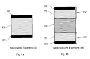
- FIG. 1b An exemplary embodiment of such a multilayer element M is shown in FIG. 1b ).
- D1 means the lower cover layer and D2 the upper cover layer.
- At least one foamed core layer K2 the intermediate layer Z1 below the core layer K2 and the intermediate layer Z2 above the core layer are formed between the two cover layers, the layers Z1 and Z2 originating from the cleavage of a first core layer K1 of a sandwich element S, which is an example in FIG. 1a ) is shown.
- both the layers Z1 and Z2 and the layer K2 are made of foamed polyurethane.
- the possible embodiments of the multilayer element M or of the sandwich panel S include those in which one or both cover layers D1 and / or D2 itself consist of several layers, or the cover layers D1 and / or D2 before the manufacture of the Sandwich panels are provided with an additional layer (eg by spraying or dipping).
- an additional layer eg by spraying or dipping.
- a bonding agent layer HV should be mentioned, as it is also described in the prior art.
- lower cover layers containing mats, scrims, knitted fabrics made of glass, plastic, carbon or natural fibers can be used in the multi-layer element.
- the multilayer element M preferably has the layer sequence D1- (HV) -Z1-K2-Z2- (HV) -D2.
- the core layer K1 In order to ensure a good cleavage of the core layer K1, it must have a certain minimum thickness before cleavage.
- the minimum thickness is preferably 10 mm and more preferably 30 mm. Due to the process step of cleavage of the core layer K1, it is imperative that the multilayered product of the process according to the invention has two identical layers Z1 and Z2 in their chemical composition.
- the cleavage of the core layer K1 provided in the method according to the invention occurs at a point in time at which the polyurethane layer K1 reacts out and is stable, but still deformable. This point in time is determined by the parameter reaction speed of PUR1, transport speed of the sandwich panel S and distance between means for producing S and the splitter. These parameters are set at the beginning of the procedure.
- a standing blade, a saw, a wire or other sawing / cutting / splitting tool can be used for cleaving the layer K1.
- the cleavage takes place in the horizontal direction parallel to the lower cover layer D1.
- a minimum thickness of 5 mm per layer Z1 or Z2 should be maintained.
- the cleavage of the two layers does not have to be exactly in the middle, so that the resulting layers Z1 and Z2 or the two layers H1 and H2 can have different thicknesses.
- dust and other contaminants are removed from the two surfaces of the resulting layers Z1 and Z2, for example, by a fan.
- the lower layer H1 is transported further horizontally, and the upper layer is removed from the lower layer by a guide so far that the second core layer K2 can be introduced.
- the polyurethane layers K1 and K2 can each be formed from an intumescent reaction mixture comprising the polyurethane systems PUR1 or PUR2, which are provided at least from the combined mixing components isocyanate and polyol and form a PUR and / or a PIR foam.
- the mixing components are preferably combined in a mixing head.
- the possible starting materials for the layers K1 and K2 used in the polyurethane systems include all raw materials used in the PUR / PIR chemistry, with which it makes sense to form known prior art polyurethane foam materials from which multilayer elements can be produced.
- the layers K1 and K2 may differ in their chemical composition and / or in their physical properties. Therefore, it is possible to adjust the properties of the finished multi-layer element by means of the composition of the individual layers, their thickness and their sequence.
- the layers K1 and K2 may be foamed with a different amount of blowing agent with otherwise identical chemical composition, so that they have different densities. Over this example, the strength and weight of the plate can be adjusted.
- blowing agents for the foamed polyurethane layers K1 and K2 hydrocarbons eg.
- the isomers of pentane or fluorohydrocarbons e.g. HFC 245fa (1,1,1,3,3-pentafluoropropane), HFC 365mfc (1,1,1,3,3-pentafluorobutane) or mixtures thereof with HFC 227ea (heptafluoropropane).
- HFC 245fa 1,1,1,3,3-pentafluoropropane
- HFC 365mfc 1,1,3,3-pentafluorobutane
- mixtures thereof with HFC 227ea heptafluoropropane
- propellant classes e.g.
- co-blowing agents added to the intumescent reaction mixture of the isocyanate component and the polyol component it is possible to use water and / or formic acid or other organic carboxylic acids.
- additional propellant gases carbon dioxide
- catalysts, stabilizers and other auxiliaries and additives can be added to the PUR / PIR reaction mixtures for polyurethane systems PUR1 and PUR2.
- auxiliaries and additives, catalysts and the like to the reaction mixture can be supplied before or during the mixing of the polyol and isocyanate components.
- the polyurethane systems PUR1 and PUR2 can be applied in the respective DTB process, for example, with at least one slot die, with a spray head, with a quiescent or oscillating casting rake or a squeegee or any other known from the prior art applicator.
- Upper and lower cover layers of the multi-layer element may be constructed of the same material or different materials.
- cover layers for example, metal sheets or plastic or paper materials can be used.
- FIG. 1 1 shows the exemplary construction of a multilayer element M, as can be produced by the method according to the invention, and its precursor, an embodiment of the sandwich element S.
- the sandwich element (FIG. FIG. 1a ) comprises a lower cover layer D1 and an upper cover layer D2 and an intervening, first foamed polyurethane core layer K1.
- the multilayer element M (M) produced by the process according to the invention FIG. 1b ) has a second foamed polyurethane core layer K2, which is surrounded by the two polyurethane foam layers Z1 and Z2, which are formed by cleavage of the sandwich panel S from the foamed first polyurethane core layer K1.
- the cover layers D1 and D2 correspond to the cover layers of the initially produced sandwich element S.
- the layers H1 and H2 each comprise the layers D1 and Z1 or D2 and Z2.
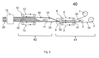
- FIG. 2 shows a device according to the invention for the production of polyurethane multilayer elements.
- the two main conveyor components are the two double belt conveyors 8 and 14 and the splitting device 9.
- the two cover layers 33 and 34 are conveyed by the respective rollers 1 and 2 so that a gap runs between them.
- the polyurethane mixture PUR1 is applied to the lower cover layer D1 with the aid of the mixing head 5.
- the double-belt conveyor 8 consisting of upper conveyor belt 6 and lower conveyor belt 7, which rotate in the direction of the arrow, the polyurethane system foams PUR1 to layer K1 and there is the sandwich element S.
- the subsequent splitting device 9 is the Sandwich element S in the core layer K1 divided into two layers (H1 and H2), each comprising a cover layer and a sub-layer of the core layer K1.
- a deflection roller 10 By a deflection roller 10, the upper layer 36 of the lower layer 35 so far away that between the two layers H1 and H2, a gap is formed and the layer H2 is passed over the mixing head 11.
- the guide and deflection can also be done by baffles or other technical solutions.
- the two layers are guided parallel in the distance corresponding to the desired thickness of the polyurethane core layer K2.
- the mixing head 11 carries the polyurethane system PUR2. While going through the second Double belt conveyor 14, consisting of upper conveyor belt 12 and lower conveyor belt 13 foams the reaction mixture from the system PUR2 to the polyurethane foam K2. After cutting (singulation) in the cutting device 15, the multi-layer element M is obtained.
- the corresponding storage containers of the respective reaction components including the isocyanate and the polyol component (s), the metering devices and lines for dosing, the mixing heads and the corresponding control devices.
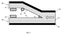
- FIG. 3 shows the details of the splitting device 9.
- a splitting blade 16 is used for splitting the polyurethane foam K1 .
- the upper layer of the sandwich element is then guided upwards by the deflection roller 10.
- the deflection roller 10 By means of two dust extractors, above 17 and below 18, the surface of the two foam layers (H1 and H2) is cleaned.
Landscapes
- Engineering & Computer Science (AREA)
- Mechanical Engineering (AREA)
- Casting Or Compression Moulding Of Plastics Or The Like (AREA)
Priority Applications (1)
| Application Number | Priority Date | Filing Date | Title |
|---|---|---|---|
| EP14154644.0A EP2905116A1 (fr) | 2014-02-11 | 2014-02-11 | Procédé de fabrication d'éléments en sandwich en polyuréthane |
Applications Claiming Priority (1)
| Application Number | Priority Date | Filing Date | Title |
|---|---|---|---|
| EP14154644.0A EP2905116A1 (fr) | 2014-02-11 | 2014-02-11 | Procédé de fabrication d'éléments en sandwich en polyuréthane |
Publications (1)
| Publication Number | Publication Date |
|---|---|
| EP2905116A1 true EP2905116A1 (fr) | 2015-08-12 |
Family
ID=50101728
Family Applications (1)
| Application Number | Title | Priority Date | Filing Date |
|---|---|---|---|
| EP14154644.0A Withdrawn EP2905116A1 (fr) | 2014-02-11 | 2014-02-11 | Procédé de fabrication d'éléments en sandwich en polyuréthane |
Country Status (1)
| Country | Link |
|---|---|
| EP (1) | EP2905116A1 (fr) |
Cited By (1)
| Publication number | Priority date | Publication date | Assignee | Title |
|---|---|---|---|---|
| CN114876079A (zh) * | 2022-04-27 | 2022-08-09 | 万华节能科技(烟台)有限公司 | 一种新型双面阻燃保温夹芯板及其连续化生产方法 |
Citations (3)
| Publication number | Priority date | Publication date | Assignee | Title |
|---|---|---|---|---|
| DE1504546A1 (de) * | 1962-10-25 | 1969-04-03 | Monsanto Co | Geschichtetes Gebilde und Verfahren zu seiner Herstellung |
| FR2628355A1 (fr) * | 1988-03-08 | 1989-09-15 | Roth Sa Freres | Procede de fabrication d'un coussin a garnissage integre par coulee in situ, melange moussant et dispositif pour la mise en oeuvre de ce procede et coussin ainsi obtenu |
| DE19949775A1 (de) * | 1999-10-15 | 2001-04-19 | Alusuisse Kapa Gmbh | Verfahren und Vorrichtung zur Herstellung geschäumter Plattenware |
-
2014
- 2014-02-11 EP EP14154644.0A patent/EP2905116A1/fr not_active Withdrawn
Patent Citations (3)
| Publication number | Priority date | Publication date | Assignee | Title |
|---|---|---|---|---|
| DE1504546A1 (de) * | 1962-10-25 | 1969-04-03 | Monsanto Co | Geschichtetes Gebilde und Verfahren zu seiner Herstellung |
| FR2628355A1 (fr) * | 1988-03-08 | 1989-09-15 | Roth Sa Freres | Procede de fabrication d'un coussin a garnissage integre par coulee in situ, melange moussant et dispositif pour la mise en oeuvre de ce procede et coussin ainsi obtenu |
| DE19949775A1 (de) * | 1999-10-15 | 2001-04-19 | Alusuisse Kapa Gmbh | Verfahren und Vorrichtung zur Herstellung geschäumter Plattenware |
Cited By (1)
| Publication number | Priority date | Publication date | Assignee | Title |
|---|---|---|---|---|
| CN114876079A (zh) * | 2022-04-27 | 2022-08-09 | 万华节能科技(烟台)有限公司 | 一种新型双面阻燃保温夹芯板及其连续化生产方法 |
Similar Documents
| Publication | Publication Date | Title |
|---|---|---|
| EP2661346B1 (fr) | Procédé et dispositif destinés à appliquer des mélanges réactionnels liquides sur une couche de recouvrement | |
| DE1932761A1 (de) | Isolierplatten und Verfahren zu deren Herstellung | |
| DE3620317A1 (de) | Verfahren und doppeltransportband zum kontinuierlichen herstellen von mit deckschichten kaschierten schaumstoffbahnen | |
| DE2748238A1 (de) | Verfahren und vorrichtung zur kontinuierlichen herstellung von mit fasern verstaerktem zement | |
| DE2307577B2 (de) | Verfahren zum herstellen von ebenen mineralwollplatten sowie anlage zur durchfuehrung des verfahrens | |
| DE2461714A1 (de) | Verfahren zur herstellung eines gegen feuer bestaendigen aus teilchen bestehenden brettes | |
| DE102018112727B4 (de) | Verfahren und Anlage zur Herstellung einer Werkstoffplatte sowie Pressgutmatte | |
| EP2905116A1 (fr) | Procédé de fabrication d'éléments en sandwich en polyuréthane | |
| EP3395520A1 (fr) | Procédé de fabrication de panneaux de lamelles orientées osb à faible émission sur des composés organiques volatils (cov) | |
| EP2905117A1 (fr) | Procédé de fabrication d'éléments multicouches en polyuréthane | |
| EP0000058A1 (fr) | Procédé et installation pour la fabrication continue de blocs de mousse à section rectangulaire | |
| EP2860007A1 (fr) | Procédé de fabrication continue d'un faisceau en plastique réactif | |
| DE68921221T2 (de) | Verfahren und vorrichtung zum herstellen von platten aus mineralwolle. | |
| DE2443117A1 (de) | Verfahren zum kontinuierlichen herstellen von faserverstaerkten schichtgebilden | |
| EP0185275B1 (fr) | Procédé et dispositif pour la production de panneaux en mousse rigide, en particulier de polyuréthane | |
| DE2205603A1 (de) | Automatisiertes fliessband fuer gipsabguesse | |
| DE2144721A1 (de) | Verfahren zur kontinuierlichen Herstellung von schaumstoffgefüllten Platten | |
| DE2250488A1 (de) | Verfahren und vorrichtung zum kontinuierlichen herstellen von verbundplatten | |
| DE2653829A1 (de) | Vorrichtung und verfahren zur kontinuierlichen abscheidung | |
| DE2424322C3 (de) | Verfahren zum kontinuierlichen Herstellen von Schaumstoffblöcken | |
| DE2439649A1 (de) | Mit geschnittenen und endlosen fasern verstaerkte kunstharzformmasse in bandform | |
| EP1093859B1 (fr) | Application d'un matériau fluide sur un substrat plat | |
| DE655829C (de) | Verfahren zur Herstellung von impraegnierten Zuendstaebchen aus Pappe oder Papier | |
| DE7237770U (de) | Vorrichtung zum kontinuierlichen Her stellen von Verbundplatten | |
| DE2233208C2 (de) | Verfahren zur Herstellung von Senkstücken sowie Vorrichtung zur Durchführung des Verfahrens |
Legal Events
| Date | Code | Title | Description |
|---|---|---|---|
| PUAI | Public reference made under article 153(3) epc to a published international application that has entered the european phase |
Free format text: ORIGINAL CODE: 0009012 |
|
| AK | Designated contracting states |
Kind code of ref document: A1 Designated state(s): AL AT BE BG CH CY CZ DE DK EE ES FI FR GB GR HR HU IE IS IT LI LT LU LV MC MK MT NL NO PL PT RO RS SE SI SK SM TR |
|
| AX | Request for extension of the european patent |
Extension state: BA ME |
|
| STAA | Information on the status of an ep patent application or granted ep patent |
Free format text: STATUS: THE APPLICATION HAS BEEN WITHDRAWN |
|
| 18W | Application withdrawn |
Effective date: 20150918 |
|
| RAP1 | Party data changed (applicant data changed or rights of an application transferred) |
Owner name: COVESTRO DEUTSCHLAND AG |