EP2905190A1 - Dispositif de frein de stationnement d'une installation de freinage pneumatique - Google Patents
Dispositif de frein de stationnement d'une installation de freinage pneumatique Download PDFInfo
- Publication number
- EP2905190A1 EP2905190A1 EP15000121.2A EP15000121A EP2905190A1 EP 2905190 A1 EP2905190 A1 EP 2905190A1 EP 15000121 A EP15000121 A EP 15000121A EP 2905190 A1 EP2905190 A1 EP 2905190A1
- Authority
- EP
- European Patent Office
- Prior art keywords
- brake
- valve
- parking brake
- pressure port
- towing vehicle
- Prior art date
- Legal status (The legal status is an assumption and is not a legal conclusion. Google has not performed a legal analysis and makes no representation as to the accuracy of the status listed.)
- Granted
Links
Images


Classifications
-
- B—PERFORMING OPERATIONS; TRANSPORTING
- B60—VEHICLES IN GENERAL
- B60T—VEHICLE BRAKE CONTROL SYSTEMS OR PARTS THEREOF; BRAKE CONTROL SYSTEMS OR PARTS THEREOF, IN GENERAL; ARRANGEMENT OF BRAKING ELEMENTS ON VEHICLES IN GENERAL; PORTABLE DEVICES FOR PREVENTING UNWANTED MOVEMENT OF VEHICLES; VEHICLE MODIFICATIONS TO FACILITATE COOLING OF BRAKES
- B60T13/00—Transmitting braking action from initiating means to ultimate brake actuator with power assistance or drive; Brake systems incorporating such transmitting means, e.g. air-pressure brake systems
- B60T13/10—Transmitting braking action from initiating means to ultimate brake actuator with power assistance or drive; Brake systems incorporating such transmitting means, e.g. air-pressure brake systems with fluid assistance, drive, or release
- B60T13/66—Electrical control in fluid-pressure brake systems
- B60T13/68—Electrical control in fluid-pressure brake systems by electrically-controlled valves
- B60T13/683—Electrical control in fluid-pressure brake systems by electrically-controlled valves in pneumatic systems or parts thereof
-
- B—PERFORMING OPERATIONS; TRANSPORTING
- B60—VEHICLES IN GENERAL
- B60T—VEHICLE BRAKE CONTROL SYSTEMS OR PARTS THEREOF; BRAKE CONTROL SYSTEMS OR PARTS THEREOF, IN GENERAL; ARRANGEMENT OF BRAKING ELEMENTS ON VEHICLES IN GENERAL; PORTABLE DEVICES FOR PREVENTING UNWANTED MOVEMENT OF VEHICLES; VEHICLE MODIFICATIONS TO FACILITATE COOLING OF BRAKES
- B60T15/00—Construction arrangement, or operation of valves incorporated in power brake systems and not covered by groups B60T11/00 or B60T13/00
- B60T15/02—Application and release valves
- B60T15/04—Driver's valves
- B60T15/041—Driver's valves controlling auxiliary pressure brakes, e.g. parking or emergency brakes
Definitions
- the invention relates to a parking brake device of a pneumatic brake system of a tractor designed as a towing vehicle with the features of the preamble of claim 1.
- WABCO publication entitled "Training documents, basic course part 4", page 2 are known, in addition to the usual in compressed air brake systems in commercial vehicles components, such as reservoir, compressors, air dryers, foot brake valves, etc. also a parking brake device, which conventionally constructed air brake systems a parking brake operating device designed as a parking brake device. If the commercial vehicle has assumed a desired parking position, the driver of the utility vehicle actuates the parking brake device, whereby at least the parking brake cylinders of an axle are vented, which causes the brakes of at least one axle to be permanently fixed.
- Conventional brake systems also have a towing vehicle arranged on the trailer control valve, through which compressed air is also supplied to the towing vehicle coupling heads "brake" and "supply" is supplied.
- the towing vehicle compressed air reaches the towing vehicle coupled to the trailer, which has its own brake system.
- the injected into the trailer vehicle compressed air causes a braking of the trailer vehicle according to the braking request of the driver of the towing vehicle.
- an actuation of the parking brake device not only causes a brake application of the parking brake of the towing vehicle, but also via appropriate control and brake lines of the trailer control valve, a brake application of the trailer vehicle, as normally when reaching a parking position, not only the towing vehicle, but also the trailer vehicle permanently braked.
- a release valve is usually arranged on the trailer, by which the parking brake can be manually released. This release valve arranged on the trailer vehicle has been marketed by WABCO under the part number 963 006 001 0 for years and is described in a WABCO publication, which is available on the Internet at the following link:
- APM Air Processing Module
- Such APM are for example from the DE 10 2004 051 309 A1 , of the DE 10 2005 026 343 A1 , of the DE 10 2006 055 570 A1 , of the DE 10 2006 055 569 A1 , of the EP 1 731 393 B1 , of the EP 1 731 394 B1 and the EP 1 731 395 B1 known.
- no mechanical-pneumatic parking brake device is present; the driver initializes the parking brakes of at least the towing vehicle by operating an electrical switch.
- the invention is based on the surprising finding that the object can be achieved by arranging a valve device between the line leading from the trailer control valve to the "brake” coupling head, through which the compressed air line leading to the "brake” coupling head is connected to the coupling head " Stock "leading line can be connected.
- This valve device is arranged on the towing vehicle so that the driver entrusted with the loading and unloading can be conveniently supplied with compressed air to the trailer vehicle and thereby compressed air to the parking brakes of the trailer vehicle.
- the invention is characterized in that between the towing vehicle arranged trailer control valve and arranged on the towing vehicle coupling heads arranged on the towing vehicle valve means is arranged, through which a pneumatic connection of the brake coupling head is connectable either to a brake pressure port of the trailer control valve or to a supply pressure port of the trailer control valve and the supply coupling head.
- a particularly simple and economically favorable solution results from the fact that as a valve device such is used, which has hitherto been used exclusively for trailer vehicles as a release valve. While the release valve was otherwise used to release the brake of the trailer vehicle, it is now used in reverse action, that is, by the release valve now serving as a release valve, the parking brake of the trailer vehicle is operated.
- An advantage of using a known release valve which, for example, from WABCO under the part no. 963 006 001 0 or from the company Knorr-Bremse Systems for commercial vehicles under the part no.
- AE4261 also results from the fact that the valve is designed so that the first time the brake is applied after restart of the towing vehicle automatically a lower pressure of about 2.5 bar is applied to the connecting line of the release valve, whereby the actuating piston of the release valve automatically gets into its initial position, causing a release of the brake of the trailer vehicle.
- This allows a particularly ergonomic mode of operation of the commercial vehicle, because the driver only has to actuate the valve device for inserting the brake of the trailer vehicle, but this does not bring by separate handles back to its starting position, as the system takes over this virtually automatically, which excludes incorrect conditions.
- valve device is designed as a 2/3-way valve, wherein in a lower position of the valve device is a connection of the brake pressure port of the trailer control valve via an input port of the valve device with the brake pressure port of the brake coupling head and wherein in an upper position of the valve means there is a connection of the reservoir pressure port of the trailer control valve and the reservoir pressure port of the supply coupling head to the brake pressure port of the brake coupling head.
- the valve device is designed as a 3/3-way valve, wherein in a lower position of the valve device, a connection of the brake pressure port of the trailer control valve via an input port of the valve device with the brake pressure port of the brake coupling head, and wherein in an upper position the valve means comprises a connection of the reservoir pressure port of the trailer control valve and the reservoir pressure port of the supply coupling head with the brake pressure port of the brake coupling head, and wherein in a middle position between the lower position and the upper position of the valve means, both the brake pressure port of the brake coupling head, and the Supply pressure port of the supply coupling head are shut off.
- valve device has a housing, along the longitudinal axis of which a valve piston is displaceably arranged, which is connected to an actuating knob.
- valve device is fastened with its actuating knob by means of a mounting flange on the outside of the frame of the towing vehicle.
- the parking brake device has a parking brake operating device designed as a hand brake valve, which is connected via a check valve to a compressed air reservoir.
- the parking brake device has an air processing module with an electronically controlled air treatment unit, wherein an electronically controlled parking brake module is flanged to the air treatment unit.
- trailer control valve is designed as a trailer brake module, to which the valve device can be flanged in a modular design.
- valve device is arranged in the cab of the towing vehicle.
- valve device is designed as a solenoid valve.
- the components of the parking brake device according to the invention are provided with normal reference numerals, while the pneumatic connections or lines are marked according to DIN / ISO 6786, in deviation to DIN / ISO 8786 but each with an "L” as a prefix for better demarcation the reference numerals are indicated.
- the connection "L21" thus corresponds to the connection 21 of DIN / ISO 6786.
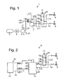
- Fig. 1 1 shows a first exemplary embodiment of a parking brake device 1 of a pneumatic brake system of a commercial vehicle designed as a towing vehicle, with only the essential components of the parking brake device being illustrated, while the other usual components of a pneumatic brake system in Fig. 1 not shown.
- the parking brake device 1 has a parking brake operating device 2, which is designed as a hand brake valve 3, is connected via a check valve 4 to a compressed air reservoir 5.
- a line L21 leads to a parking brake device, not shown, of the towing vehicle.
- a lever 6 of the hand brake valve 3 If a lever 6 of the hand brake valve 3 is actuated, compressed air from the compressed air reservoir passes via the connection L21 to the parking brake of the towing vehicle and via a brake pressure connection L22 to a brake pressure or control pressure port L43 of a trailer control valve 7, shown only schematically, known per se.
- the trailer control valve 7 has more Control terminals L11, L42 and L41 on, but it does not matter below.
- a supply pressure is looped through the supply pressure port L12 to a supply coupling head 8; the coupling head "supply” 8 is connected in the coupled vehicle of a trailer vehicle with a corresponding control line of the trailer vehicle and supplies supply pressure of the brake system of the trailer vehicle.
- An actuated brake pressure leaves the trailer control valve 7 via the brake pressure connection L22 and arrives at a coupling head "brake” or a brake coupling head 9.
- actuation of the parking brake actuator 2 would also cause a brake pressure across the brake Coupling head 9 would be controlled by the corresponding brake line of the trailer vehicle, whereby the brake of the trailer vehicle would be actuated.
- the controlled brake pressure is not controlled through to the brake of the trailer, so that the brake of the trailer remains unconfirmed.
- a valve device 10 is disposed between the brake pressure port L22 on the trailer control valve 7 and the brake pressure port L2 of the brake coupling head 9. This valve device 10 is arranged on the towing vehicle, which is based on Fig. 5 will be explained in more detail.
- the valve device 10 whose structural design in connection with Fig. 3 will be explained in more detail, is designed as a 3/3-way valve and has an actuating knob 11. In the normal state of a lower position 10a, which in Fig. 1 is shown, there is a connection from the brake pressure port L22 to the brake pressure port L2 of the brake coupling head 9, so that the brake cylinder of the parking brake system of the trailer vehicle ventilated and its brake is thus ineffective.
- the valve When the button 11 is depressed, the valve is shifted from the lower position 10a via a middle position 10b to an upper position 10c, whereby the terminals L22 of the trailer brake valve 7 and the port L2 of the brake coupling head 9 separated and instead the supply terminal L12 with the terminal L2 of the brake coupling head 9 are connected, whereby the brakes of the trailer vehicle are activated.
- the driver then starts after successful loading and unloading the towing vehicle and activates the brake system of the vehicle for the first time, passes a minimum pressure of about 2.5 bar via the input terminal L11 in the valve device 10, which causes the valve piston of the valve device 10 is pushed up and the terminal L22 is reconnected to the terminal L2 of the brake coupling head 9, which in turn results in that the braking device of the trailer vehicle is released.
- a second embodiment of a parking brake device 1 a is shown, in which the same reference numerals and terminal identifiers are used for the same parts.
- the parking brake device 1 a according to Fig. 2 differs from the parking brake device 1 according to Fig. 1 in that no mechanical-pneumatic parking brake device is present here.
- a so-called "Air Processing Module 12" or APM 12 is present in the parking brake device 1 a according to Fig. 2 Instead, a so-called "Air Processing Module 12" or APM 12 is present.
- This consists of an electronically controlled air treatment unit 13, which electronically controlled by a compressor connected to the engine of the towing vehicle compressor cleans and a in Fig. 2 not shown supply reservoir.
- an electronically controlled parking brake module 14 is flanged.
- a trailer brake module 15 This is activated by an in-cab switch for activating the parking brake.
- air pressure via a port L28.1 to parking brakes, not shown the towing vehicle and via terminals L28.2 and L23 to terminals L1 and L43 of a trailer brake module 15 indicated only schematically.
- This takes over the function of the trailer control valve 7 Fig. 1 and can be constructed like this.
- the trailer brake module 15 fulfills further functions and is provided with independent control logic, wherein it is also possible to hook the trailer brake module 15 to the air conditioning unit 13 or to the parking brake module 14, so that in this case a structural unit of air conditioning unit 13, parking brake module 14 and trailer brake module 15 results.
- the other components of the parking brake device 1a according to Fig. 2 correspond to those from Fig. 1 What applies in particular with regard to the valve device 10.
- the valve device 10 in deviation from the illustration according to the Fig. 1 and 2 be designed as a 2/3-way valve.
- the middle position 10b would be omitted, in which all three ports L11, L12, L2 are separated from each other.
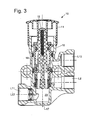
- Fig. 3 is the valve device 10 of Figures 1 and 2 shown in longitudinal section.
- the valve device 10 corresponds in construction terms to a release valve known valve, which is sold by the company WABCO under the part number 963 006 001 0.
- the valve device 10 according to the invention but not as a release valve, but as a check valve, since after pressing, that is, depression, the operating knob 11, first, the terminals L11, L22 and L2 are separated from each other - which the middle position 10b of Fig. 1 and 2 corresponds to - then, ie when reaching the upper position 10c, the terminals L2 and L12 are connected to each other, resulting in the actuation of the braking device of the trailer vehicle.
- the valve device 10 has a housing 16, along the longitudinal axis 17, a valve piston 18 is slidably disposed.
- the valve piston 18 is connected by means of a screw 19 with the actuating knob 11.
- the valve piston 18 is in its maximum extended, that is axially upper position, which is the lower position 10a of Fig. 1 and 2 equivalent.
- the device port L11 or L22 is connected to the brake pressure port L2.
- the brake pressure port L2 is connected to the supply port L12. This causes the brake of the trailer vehicle is activated. The trailer is then braked.
- an "X" means the minimum pressure that is necessary to bring the valve piston 18 of the valve device in its release position, ie upwards. As a rule, this minimum value is approx. 2.5 bar.
- a commercial vehicle 21 is shown from the side.
- the commercial vehicle 21 consists of a combination of a towing vehicle 22 and a trailer vehicle 23, wherein the trailer vehicle 23 is shown only very schematically.
- the trailer vehicle 23 is mechanically coupled to the tractor 22 in a suitable manner, not shown.
- the trailer vehicle 23 may also be a semi-trailer, which rests on a frame 24 of the towing vehicle.
- the parking brake device 1a from Fig. 2 attached to the frame 24 of the towing vehicle.
- the air processing module 12 which has an air treatment unit 13 with attached filter cartridge 25.
- the parking brake module 14 is flanged to the air treatment unit 13.
- the parking brake module 14 is connected to the trailer brake module 15 via lines L23 and L28.2.
- the terminal L22 of the trailer brake module 15 is pneumatically connected via a connecting line 27 with the in Fig. 5 not shown input terminal L11 of the valve device 10 connected.
- the valve device 10 is in turn connected via a connecting line not shown with a brake line 28 to the brake pressure port L2 of the brake coupling head 9, which in turn is connected via a brake line 29 to the brake system of the trailer vehicle 23, not shown.
- the valve device 10 is connected via a connecting line, not shown, with a supply line 30 to the supply terminal L12 of the supply coupling head 8, which is connected via a supply line 31 with the brake system of the trailer vehicle 23, not shown.
- valve device 10 is screwed quasi-lying with its operating knob 11 via a mounting flange 32 on the frame 24 of the towing vehicle 22.
- the installation position shown on towing vehicle 22 allows the driver to conveniently press the actuating head 11 before loading and unloading, whereby the parking brake of the trailer vehicle 23 is actuated.
- valve device 10 at another point of the towing vehicle, for example, it is possible to flangle the valve device 10 in a modular design on the trailer braking module 15. Also conceivable is an attachment of the valve device in the cab 33rd However, for safety reasons, an attachment outside of the towing vehicle 22 will be preferred.
- valve device 10 could be electrically operated, for example by simply pressing a on or in the towing vehicle 22 arranged pushbutton.
- the motorized actuator can be wired or wireless.
- the remote control can be designed as a special software program or "app" of a smartphone.
- remote control could be further functions of the commercial vehicle 21 control during loading and unloading, such as lifting and lowering the trailer vehicle, the lifting and lowering a towing axle, and the like.
- valve device 10 it is also possible to design the valve device 10 as a solenoid valve. In this case, the control of the valve device would be purely electrical or electronic. In this case too, it would be possible to switch the valve device 10 embodied as a solenoid valve by means of a remote control, which may be designed as shown above.
Landscapes
- Engineering & Computer Science (AREA)
- Transportation (AREA)
- Mechanical Engineering (AREA)
- Valves And Accessory Devices For Braking Systems (AREA)
- Regulating Braking Force (AREA)
- Braking Systems And Boosters (AREA)
Applications Claiming Priority (1)
| Application Number | Priority Date | Filing Date | Title |
|---|---|---|---|
| DE102014001237.9A DE102014001237A1 (de) | 2014-01-28 | 2014-01-28 | Feststellbremsvorrichtung einer pneumatischen Bremsanlage |
Publications (2)
| Publication Number | Publication Date |
|---|---|
| EP2905190A1 true EP2905190A1 (fr) | 2015-08-12 |
| EP2905190B1 EP2905190B1 (fr) | 2016-09-21 |
Family
ID=52394877
Family Applications (1)
| Application Number | Title | Priority Date | Filing Date |
|---|---|---|---|
| EP15000121.2A Active EP2905190B1 (fr) | 2014-01-28 | 2015-01-17 | Dispositif de frein de stationnement d'une installation de freinage pneumatique |
Country Status (2)
| Country | Link |
|---|---|
| EP (1) | EP2905190B1 (fr) |
| DE (1) | DE102014001237A1 (fr) |
Cited By (1)
| Publication number | Priority date | Publication date | Assignee | Title |
|---|---|---|---|---|
| WO2018183305A1 (fr) * | 2017-03-27 | 2018-10-04 | Bendix Commercial Vehicle Systems Llc | Système de soupape et procédé de commande associé |
Families Citing this family (1)
| Publication number | Priority date | Publication date | Assignee | Title |
|---|---|---|---|---|
| DE102021118755A1 (de) | 2021-07-20 | 2023-01-26 | Man Truck & Bus Se | Nutzfahrzeug mit einer Schnittstelle zum Verbinden mit einem Notsteuergerät und entsprechendes Notsteuergerät |
Citations (9)
| Publication number | Priority date | Publication date | Assignee | Title |
|---|---|---|---|---|
| FR2651196A1 (fr) * | 1989-08-31 | 1991-03-01 | Bosch Gmbh Robert | Robinet de commande de remorque pour freins de vehicules automobiles. |
| EP0941905A2 (fr) * | 1998-03-12 | 1999-09-15 | DaimlerChrysler AG | Procédé pour la stabilisation des attelages et système de freinage pour attelages |
| EP1188634A2 (fr) * | 2000-09-14 | 2002-03-20 | WABCO GmbH & Co. OHG | Soupape de frein de remorque pour remorques à commande de freinage électronique et à sécurité améliorée de remorque stationnée |
| DE102004051309A1 (de) | 2004-10-21 | 2006-05-11 | Knorr-Bremse Systeme für Nutzfahrzeuge GmbH | Aus Moduln mit elektrischen und/oder pneumatischen Komponenten aufgebaute elektro-pneumatische Zentraleinheit eines Nutzfahzeugs |
| DE102005026343A1 (de) | 2005-06-08 | 2006-12-14 | Knorr-Bremse Systeme für Nutzfahrzeuge GmbH | Druckluftversorgungseinrichtung |
| DE102006055569A1 (de) | 2006-11-24 | 2008-05-29 | Knorr-Bremse Systeme für Nutzfahrzeuge GmbH | Feststellbremsvorrichtung mit Druckluftversorgungsleitungen für eine Feststellbremse |
| DE102006055570A1 (de) | 2006-11-24 | 2008-05-29 | Knorr-Bremse Systeme für Nutzfahrzeuge GmbH | Feststellbremsvorrichtung mit einer Feststellbremse-Notlöseeinrichtung |
| EP1731394B1 (fr) | 2005-06-08 | 2009-01-07 | KNORR-BREMSE SYSTEME FÜR NUTZFAHRZEUGE GmbH | Installation d'alimentation en air comprimé |
| EP1731393B1 (fr) | 2005-06-10 | 2013-03-20 | KNORR-BREMSE Systeme für Nutzfahrzeuge GmbH | Système de traitement d'air et module de frein de stationnement pour un système de freinage d'un véhicule utilitaire |
-
2014
- 2014-01-28 DE DE102014001237.9A patent/DE102014001237A1/de not_active Withdrawn
-
2015
- 2015-01-17 EP EP15000121.2A patent/EP2905190B1/fr active Active
Patent Citations (10)
| Publication number | Priority date | Publication date | Assignee | Title |
|---|---|---|---|---|
| FR2651196A1 (fr) * | 1989-08-31 | 1991-03-01 | Bosch Gmbh Robert | Robinet de commande de remorque pour freins de vehicules automobiles. |
| EP0941905A2 (fr) * | 1998-03-12 | 1999-09-15 | DaimlerChrysler AG | Procédé pour la stabilisation des attelages et système de freinage pour attelages |
| EP1188634A2 (fr) * | 2000-09-14 | 2002-03-20 | WABCO GmbH & Co. OHG | Soupape de frein de remorque pour remorques à commande de freinage électronique et à sécurité améliorée de remorque stationnée |
| DE102004051309A1 (de) | 2004-10-21 | 2006-05-11 | Knorr-Bremse Systeme für Nutzfahrzeuge GmbH | Aus Moduln mit elektrischen und/oder pneumatischen Komponenten aufgebaute elektro-pneumatische Zentraleinheit eines Nutzfahzeugs |
| DE102005026343A1 (de) | 2005-06-08 | 2006-12-14 | Knorr-Bremse Systeme für Nutzfahrzeuge GmbH | Druckluftversorgungseinrichtung |
| EP1731394B1 (fr) | 2005-06-08 | 2009-01-07 | KNORR-BREMSE SYSTEME FÜR NUTZFAHRZEUGE GmbH | Installation d'alimentation en air comprimé |
| EP1731395B1 (fr) | 2005-06-08 | 2010-07-28 | KNORR-BREMSE Systeme für Nutzfahrzeuge GmbH | Installation d'alimentation en air comprimé |
| EP1731393B1 (fr) | 2005-06-10 | 2013-03-20 | KNORR-BREMSE Systeme für Nutzfahrzeuge GmbH | Système de traitement d'air et module de frein de stationnement pour un système de freinage d'un véhicule utilitaire |
| DE102006055569A1 (de) | 2006-11-24 | 2008-05-29 | Knorr-Bremse Systeme für Nutzfahrzeuge GmbH | Feststellbremsvorrichtung mit Druckluftversorgungsleitungen für eine Feststellbremse |
| DE102006055570A1 (de) | 2006-11-24 | 2008-05-29 | Knorr-Bremse Systeme für Nutzfahrzeuge GmbH | Feststellbremsvorrichtung mit einer Feststellbremse-Notlöseeinrichtung |
Cited By (1)
| Publication number | Priority date | Publication date | Assignee | Title |
|---|---|---|---|---|
| WO2018183305A1 (fr) * | 2017-03-27 | 2018-10-04 | Bendix Commercial Vehicle Systems Llc | Système de soupape et procédé de commande associé |
Also Published As
| Publication number | Publication date |
|---|---|
| EP2905190B1 (fr) | 2016-09-21 |
| DE102014001237A1 (de) | 2015-07-30 |
Similar Documents
| Publication | Publication Date | Title |
|---|---|---|
| EP2567874B1 (fr) | Composant de soupape pour une installation de freinage d'une remorque | |
| EP1963151B1 (fr) | Dispositif électropneumatique de commande de frein | |
| EP2121397B1 (fr) | Module frein de stationnement pour dispositif de freinage actionné par fluide sous pression | |
| EP3668767B1 (fr) | Module de frein de stationnement électropneumatique avec vannes à commande directe | |
| EP3129265B1 (fr) | Dispositif de commande électromagnétique de frein destiné à commander un frein à ressort accumulateur | |
| EP3022099B1 (fr) | Dispositif de freinage de stationnement pour un véhicule tracteur d'une combinaison de véhicule tracteur-remorque présentant un dispositif de soupape pour frein de maintien en ligne pouvant être rattrapé | |
| EP3145769B1 (fr) | Moyen de commande de freinage électropneumatique avec purge automatique du frein à accumulation en cas de panne de courant | |
| EP2055542B1 (fr) | Dispositif de frein actionné par un moyen de pression d'un véhicule sur rail doté d'un module de frein fixe produisant une pression contraire pour des freins de remorque | |
| EP3515770B1 (fr) | Arrangement de vannes de frein de stationnement pour commander un frein d'immobilisation à ressort accumulateur | |
| EP3823868B1 (fr) | Module de frein de stationnement électropneumatique pourvu de soupapes à commande directe et d'un raccord de non-addition des efforts de freinage | |
| EP1464557A1 (fr) | Dispositif de traitement d'air comprimé | |
| DE102007053767B3 (de) | Feststellbremsventil für eine Steueranlage für Kraftfahrzeug-Anhänger mit Betriebsbremse, Feststellbremse und Luftfederung | |
| DE102017008184A1 (de) | Parkbrems-Ventileinrichtung | |
| EP3971046B1 (fr) | Agencement de soupape d'un véhicule tracteur destiné à la commande d'une installation pneumatique de freinage d'un véhicule remorque et son procédé de commande | |
| EP3307594B1 (fr) | Système de frein pneumatique pour un véhicule tracté | |
| EP3368387A1 (fr) | Dispositif de frein de stationnement électro-pneumatique à commande pneumatique redondante | |
| EP3829946B2 (fr) | Frein à main électropneumatique (ebh) avec tcv partiellement decouplé (type d'activation européen) | |
| DE102019125747A1 (de) | Elektropneumatische Parkbremsventileinheit | |
| EP3774403B1 (fr) | Dispositif de régulation de la pression des pneumatiques d'un véhicule hors route monté sur pneumatiques | |
| DE202018001859U1 (de) | Bremssystem eines Zugfahrzeugs | |
| EP2082935B1 (fr) | Dispositif de freinage d'une remorque ayant au moins deux axes et comprenant un axe avant articulé d'une combinaison de remorque de véhicule de traction | |
| EP3253630A1 (fr) | Procédé permettant de régler les pressions de freinage d'un véhicule automobile par commande d'une soupape de commande de pression, système de freinage permettant la mise en uvre du procédé, et véhicule automobile | |
| EP2905190B1 (fr) | Dispositif de frein de stationnement d'une installation de freinage pneumatique | |
| AT408213B (de) | Hydraulische bremsanlage | |
| DE1119686B (de) | Druckluftverteilanlage fuer pneumatische Federungen, insbesondere von Anhaengerfahrzeugen |
Legal Events
| Date | Code | Title | Description |
|---|---|---|---|
| PUAI | Public reference made under article 153(3) epc to a published international application that has entered the european phase |
Free format text: ORIGINAL CODE: 0009012 |
|
| AK | Designated contracting states |
Kind code of ref document: A1 Designated state(s): AL AT BE BG CH CY CZ DE DK EE ES FI FR GB GR HR HU IE IS IT LI LT LU LV MC MK MT NL NO PL PT RO RS SE SI SK SM TR |
|
| AX | Request for extension of the european patent |
Extension state: BA ME |
|
| 17P | Request for examination filed |
Effective date: 20160212 |
|
| RBV | Designated contracting states (corrected) |
Designated state(s): AL AT BE BG CH CY CZ DE DK EE ES FI FR GB GR HR HU IE IS IT LI LT LU LV MC MK MT NL NO PL PT RO RS SE SI SK SM TR |
|
| GRAP | Despatch of communication of intention to grant a patent |
Free format text: ORIGINAL CODE: EPIDOSNIGR1 |
|
| RIC1 | Information provided on ipc code assigned before grant |
Ipc: B60T 13/68 20060101AFI20160530BHEP Ipc: B60T 15/04 20060101ALI20160530BHEP |
|
| INTG | Intention to grant announced |
Effective date: 20160630 |
|
| GRAS | Grant fee paid |
Free format text: ORIGINAL CODE: EPIDOSNIGR3 |
|
| GRAA | (expected) grant |
Free format text: ORIGINAL CODE: 0009210 |
|
| AK | Designated contracting states |
Kind code of ref document: B1 Designated state(s): AL AT BE BG CH CY CZ DE DK EE ES FI FR GB GR HR HU IE IS IT LI LT LU LV MC MK MT NL NO PL PT RO RS SE SI SK SM TR |
|
| REG | Reference to a national code |
Ref country code: GB Ref legal event code: FG4D Free format text: NOT ENGLISH |
|
| REG | Reference to a national code |
Ref country code: CH Ref legal event code: EP |
|
| REG | Reference to a national code |
Ref country code: AT Ref legal event code: REF Ref document number: 830766 Country of ref document: AT Kind code of ref document: T Effective date: 20161015 |
|
| REG | Reference to a national code |
Ref country code: IE Ref legal event code: FG4D Free format text: LANGUAGE OF EP DOCUMENT: GERMAN |
|
| REG | Reference to a national code |
Ref country code: DE Ref legal event code: R096 Ref document number: 502015000159 Country of ref document: DE |
|
| REG | Reference to a national code |
Ref country code: NL Ref legal event code: FP |
|
| REG | Reference to a national code |
Ref country code: SE Ref legal event code: TRGR |
|
| REG | Reference to a national code |
Ref country code: FR Ref legal event code: PLFP Year of fee payment: 3 |
|
| REG | Reference to a national code |
Ref country code: LT Ref legal event code: MG4D |
|
| PG25 | Lapsed in a contracting state [announced via postgrant information from national office to epo] |
Ref country code: NO Free format text: LAPSE BECAUSE OF FAILURE TO SUBMIT A TRANSLATION OF THE DESCRIPTION OR TO PAY THE FEE WITHIN THE PRESCRIBED TIME-LIMIT Effective date: 20161221 Ref country code: RS Free format text: LAPSE BECAUSE OF FAILURE TO SUBMIT A TRANSLATION OF THE DESCRIPTION OR TO PAY THE FEE WITHIN THE PRESCRIBED TIME-LIMIT Effective date: 20160921 Ref country code: LT Free format text: LAPSE BECAUSE OF FAILURE TO SUBMIT A TRANSLATION OF THE DESCRIPTION OR TO PAY THE FEE WITHIN THE PRESCRIBED TIME-LIMIT Effective date: 20160921 Ref country code: FI Free format text: LAPSE BECAUSE OF FAILURE TO SUBMIT A TRANSLATION OF THE DESCRIPTION OR TO PAY THE FEE WITHIN THE PRESCRIBED TIME-LIMIT Effective date: 20160921 |
|
| PG25 | Lapsed in a contracting state [announced via postgrant information from national office to epo] |
Ref country code: LV Free format text: LAPSE BECAUSE OF FAILURE TO SUBMIT A TRANSLATION OF THE DESCRIPTION OR TO PAY THE FEE WITHIN THE PRESCRIBED TIME-LIMIT Effective date: 20160921 Ref country code: GR Free format text: LAPSE BECAUSE OF FAILURE TO SUBMIT A TRANSLATION OF THE DESCRIPTION OR TO PAY THE FEE WITHIN THE PRESCRIBED TIME-LIMIT Effective date: 20161222 |
|
| PG25 | Lapsed in a contracting state [announced via postgrant information from national office to epo] |
Ref country code: EE Free format text: LAPSE BECAUSE OF FAILURE TO SUBMIT A TRANSLATION OF THE DESCRIPTION OR TO PAY THE FEE WITHIN THE PRESCRIBED TIME-LIMIT Effective date: 20160921 Ref country code: RO Free format text: LAPSE BECAUSE OF FAILURE TO SUBMIT A TRANSLATION OF THE DESCRIPTION OR TO PAY THE FEE WITHIN THE PRESCRIBED TIME-LIMIT Effective date: 20160921 |
|
| PG25 | Lapsed in a contracting state [announced via postgrant information from national office to epo] |
Ref country code: SM Free format text: LAPSE BECAUSE OF FAILURE TO SUBMIT A TRANSLATION OF THE DESCRIPTION OR TO PAY THE FEE WITHIN THE PRESCRIBED TIME-LIMIT Effective date: 20160921 Ref country code: PL Free format text: LAPSE BECAUSE OF FAILURE TO SUBMIT A TRANSLATION OF THE DESCRIPTION OR TO PAY THE FEE WITHIN THE PRESCRIBED TIME-LIMIT Effective date: 20160921 Ref country code: IS Free format text: LAPSE BECAUSE OF FAILURE TO SUBMIT A TRANSLATION OF THE DESCRIPTION OR TO PAY THE FEE WITHIN THE PRESCRIBED TIME-LIMIT Effective date: 20170121 Ref country code: SK Free format text: LAPSE BECAUSE OF FAILURE TO SUBMIT A TRANSLATION OF THE DESCRIPTION OR TO PAY THE FEE WITHIN THE PRESCRIBED TIME-LIMIT Effective date: 20160921 Ref country code: ES Free format text: LAPSE BECAUSE OF FAILURE TO SUBMIT A TRANSLATION OF THE DESCRIPTION OR TO PAY THE FEE WITHIN THE PRESCRIBED TIME-LIMIT Effective date: 20160921 Ref country code: BE Free format text: LAPSE BECAUSE OF NON-PAYMENT OF DUE FEES Effective date: 20170131 Ref country code: CZ Free format text: LAPSE BECAUSE OF FAILURE TO SUBMIT A TRANSLATION OF THE DESCRIPTION OR TO PAY THE FEE WITHIN THE PRESCRIBED TIME-LIMIT Effective date: 20160921 Ref country code: PT Free format text: LAPSE BECAUSE OF FAILURE TO SUBMIT A TRANSLATION OF THE DESCRIPTION OR TO PAY THE FEE WITHIN THE PRESCRIBED TIME-LIMIT Effective date: 20170123 Ref country code: BG Free format text: LAPSE BECAUSE OF FAILURE TO SUBMIT A TRANSLATION OF THE DESCRIPTION OR TO PAY THE FEE WITHIN THE PRESCRIBED TIME-LIMIT Effective date: 20161221 |
|
| REG | Reference to a national code |
Ref country code: DE Ref legal event code: R097 Ref document number: 502015000159 Country of ref document: DE |
|
| PG25 | Lapsed in a contracting state [announced via postgrant information from national office to epo] |
Ref country code: IT Free format text: LAPSE BECAUSE OF FAILURE TO SUBMIT A TRANSLATION OF THE DESCRIPTION OR TO PAY THE FEE WITHIN THE PRESCRIBED TIME-LIMIT Effective date: 20160921 |
|
| PLBE | No opposition filed within time limit |
Free format text: ORIGINAL CODE: 0009261 |
|
| STAA | Information on the status of an ep patent application or granted ep patent |
Free format text: STATUS: NO OPPOSITION FILED WITHIN TIME LIMIT |
|
| PG25 | Lapsed in a contracting state [announced via postgrant information from national office to epo] |
Ref country code: DK Free format text: LAPSE BECAUSE OF FAILURE TO SUBMIT A TRANSLATION OF THE DESCRIPTION OR TO PAY THE FEE WITHIN THE PRESCRIBED TIME-LIMIT Effective date: 20160921 |
|
| 26N | No opposition filed |
Effective date: 20170622 |
|
| PG25 | Lapsed in a contracting state [announced via postgrant information from national office to epo] |
Ref country code: MC Free format text: LAPSE BECAUSE OF FAILURE TO SUBMIT A TRANSLATION OF THE DESCRIPTION OR TO PAY THE FEE WITHIN THE PRESCRIBED TIME-LIMIT Effective date: 20160921 |
|
| REG | Reference to a national code |
Ref country code: IE Ref legal event code: MM4A |
|
| PG25 | Lapsed in a contracting state [announced via postgrant information from national office to epo] |
Ref country code: SI Free format text: LAPSE BECAUSE OF FAILURE TO SUBMIT A TRANSLATION OF THE DESCRIPTION OR TO PAY THE FEE WITHIN THE PRESCRIBED TIME-LIMIT Effective date: 20160921 Ref country code: LU Free format text: LAPSE BECAUSE OF NON-PAYMENT OF DUE FEES Effective date: 20170117 |
|
| REG | Reference to a national code |
Ref country code: DE Ref legal event code: R081 Ref document number: 502015000159 Country of ref document: DE Owner name: WABCO EUROPE BVBA, BE Free format text: FORMER OWNER: WABCO GMBH, 30453 HANNOVER, DE |
|
| REG | Reference to a national code |
Ref country code: FR Ref legal event code: PLFP Year of fee payment: 4 |
|
| REG | Reference to a national code |
Ref country code: BE Ref legal event code: MM Effective date: 20170131 |
|
| PG25 | Lapsed in a contracting state [announced via postgrant information from national office to epo] |
Ref country code: IE Free format text: LAPSE BECAUSE OF NON-PAYMENT OF DUE FEES Effective date: 20170117 |
|
| REG | Reference to a national code |
Ref country code: CH Ref legal event code: PL |
|
| PG25 | Lapsed in a contracting state [announced via postgrant information from national office to epo] |
Ref country code: MT Free format text: LAPSE BECAUSE OF FAILURE TO SUBMIT A TRANSLATION OF THE DESCRIPTION OR TO PAY THE FEE WITHIN THE PRESCRIBED TIME-LIMIT Effective date: 20160921 |
|
| PG25 | Lapsed in a contracting state [announced via postgrant information from national office to epo] |
Ref country code: AL Free format text: LAPSE BECAUSE OF FAILURE TO SUBMIT A TRANSLATION OF THE DESCRIPTION OR TO PAY THE FEE WITHIN THE PRESCRIBED TIME-LIMIT Effective date: 20160921 |
|
| PG25 | Lapsed in a contracting state [announced via postgrant information from national office to epo] |
Ref country code: LI Free format text: LAPSE BECAUSE OF NON-PAYMENT OF DUE FEES Effective date: 20180131 Ref country code: CH Free format text: LAPSE BECAUSE OF NON-PAYMENT OF DUE FEES Effective date: 20180131 |
|
| PG25 | Lapsed in a contracting state [announced via postgrant information from national office to epo] |
Ref country code: HU Free format text: LAPSE BECAUSE OF FAILURE TO SUBMIT A TRANSLATION OF THE DESCRIPTION OR TO PAY THE FEE WITHIN THE PRESCRIBED TIME-LIMIT; INVALID AB INITIO Effective date: 20150117 |
|
| GBPC | Gb: european patent ceased through non-payment of renewal fee |
Effective date: 20190117 |
|
| PG25 | Lapsed in a contracting state [announced via postgrant information from national office to epo] |
Ref country code: CY Free format text: LAPSE BECAUSE OF FAILURE TO SUBMIT A TRANSLATION OF THE DESCRIPTION OR TO PAY THE FEE WITHIN THE PRESCRIBED TIME-LIMIT Effective date: 20160921 |
|
| PG25 | Lapsed in a contracting state [announced via postgrant information from national office to epo] |
Ref country code: MK Free format text: LAPSE BECAUSE OF FAILURE TO SUBMIT A TRANSLATION OF THE DESCRIPTION OR TO PAY THE FEE WITHIN THE PRESCRIBED TIME-LIMIT Effective date: 20160921 |
|
| PG25 | Lapsed in a contracting state [announced via postgrant information from national office to epo] |
Ref country code: GB Free format text: LAPSE BECAUSE OF NON-PAYMENT OF DUE FEES Effective date: 20190117 |
|
| PG25 | Lapsed in a contracting state [announced via postgrant information from national office to epo] |
Ref country code: TR Free format text: LAPSE BECAUSE OF FAILURE TO SUBMIT A TRANSLATION OF THE DESCRIPTION OR TO PAY THE FEE WITHIN THE PRESCRIBED TIME-LIMIT Effective date: 20160921 |
|
| PG25 | Lapsed in a contracting state [announced via postgrant information from national office to epo] |
Ref country code: HR Free format text: LAPSE BECAUSE OF FAILURE TO SUBMIT A TRANSLATION OF THE DESCRIPTION OR TO PAY THE FEE WITHIN THE PRESCRIBED TIME-LIMIT Effective date: 20160921 |
|
| REG | Reference to a national code |
Ref country code: AT Ref legal event code: MM01 Ref document number: 830766 Country of ref document: AT Kind code of ref document: T Effective date: 20200117 |
|
| PG25 | Lapsed in a contracting state [announced via postgrant information from national office to epo] |
Ref country code: AT Free format text: LAPSE BECAUSE OF NON-PAYMENT OF DUE FEES Effective date: 20200117 |
|
| PGFP | Annual fee paid to national office [announced via postgrant information from national office to epo] |
Ref country code: FR Payment date: 20230123 Year of fee payment: 9 |
|
| REG | Reference to a national code |
Ref country code: DE Ref legal event code: R081 Ref document number: 502015000159 Country of ref document: DE Owner name: ZF CV SYSTEMS EUROPE BV, BE Free format text: FORMER OWNER: WABCO EUROPE BVBA, BRUESSEL, BE |
|
| PGFP | Annual fee paid to national office [announced via postgrant information from national office to epo] |
Ref country code: NL Payment date: 20230124 Year of fee payment: 9 |
|
| P01 | Opt-out of the competence of the unified patent court (upc) registered |
Effective date: 20230528 |
|
| REG | Reference to a national code |
Ref country code: NL Ref legal event code: MM Effective date: 20240201 |
|
| PG25 | Lapsed in a contracting state [announced via postgrant information from national office to epo] |
Ref country code: FR Free format text: LAPSE BECAUSE OF NON-PAYMENT OF DUE FEES Effective date: 20240131 |
|
| PG25 | Lapsed in a contracting state [announced via postgrant information from national office to epo] |
Ref country code: NL Free format text: LAPSE BECAUSE OF NON-PAYMENT OF DUE FEES Effective date: 20240201 |
|
| PG25 | Lapsed in a contracting state [announced via postgrant information from national office to epo] |
Ref country code: NL Free format text: LAPSE BECAUSE OF NON-PAYMENT OF DUE FEES Effective date: 20240201 Ref country code: FR Free format text: LAPSE BECAUSE OF NON-PAYMENT OF DUE FEES Effective date: 20240131 |
|
| PGFP | Annual fee paid to national office [announced via postgrant information from national office to epo] |
Ref country code: SE Payment date: 20251210 Year of fee payment: 12 |
|
| PGFP | Annual fee paid to national office [announced via postgrant information from national office to epo] |
Ref country code: DE Payment date: 20251203 Year of fee payment: 12 |