EP2905191A1 - Fahrzeugluftkompressorvorrichtung für ein Druckluftbremssystem für Schwerfahrzeuge - Google Patents
Fahrzeugluftkompressorvorrichtung für ein Druckluftbremssystem für Schwerfahrzeuge Download PDFInfo
- Publication number
- EP2905191A1 EP2905191A1 EP15153171.2A EP15153171A EP2905191A1 EP 2905191 A1 EP2905191 A1 EP 2905191A1 EP 15153171 A EP15153171 A EP 15153171A EP 2905191 A1 EP2905191 A1 EP 2905191A1
- Authority
- EP
- European Patent Office
- Prior art keywords
- jumper
- air
- cylinder head
- discharge
- head assembly
- Prior art date
- Legal status (The legal status is an assumption and is not a legal conclusion. Google has not performed a legal analysis and makes no representation as to the accuracy of the status listed.)
- Granted
Links
- 238000001816 cooling Methods 0.000 claims abstract description 100
- 238000007906 compression Methods 0.000 claims abstract description 10
- 230000006835 compression Effects 0.000 claims abstract description 9
- 230000000712 assembly Effects 0.000 claims description 8
- 238000000429 assembly Methods 0.000 claims description 8
- 238000004891 communication Methods 0.000 claims description 7
- 239000012530 fluid Substances 0.000 claims description 7
- 238000000034 method Methods 0.000 claims description 4
- 238000009420 retrofitting Methods 0.000 claims 1
- 239000003570 air Substances 0.000 description 163
- 239000012080 ambient air Substances 0.000 description 6
- 239000002826 coolant Substances 0.000 description 5
- 238000010276 construction Methods 0.000 description 4
- 239000000463 material Substances 0.000 description 4
- 230000008901 benefit Effects 0.000 description 3
- 230000004048 modification Effects 0.000 description 3
- 238000012986 modification Methods 0.000 description 3
- 238000010926 purge Methods 0.000 description 3
- 238000007605 air drying Methods 0.000 description 2
- 239000007769 metal material Substances 0.000 description 2
- 238000012544 monitoring process Methods 0.000 description 2
- 230000008569 process Effects 0.000 description 2
- 230000009467 reduction Effects 0.000 description 2
- OKTJSMMVPCPJKN-UHFFFAOYSA-N Carbon Chemical compound [C] OKTJSMMVPCPJKN-UHFFFAOYSA-N 0.000 description 1
- 229910052782 aluminium Inorganic materials 0.000 description 1
- XAGFODPZIPBFFR-UHFFFAOYSA-N aluminium Chemical compound [Al] XAGFODPZIPBFFR-UHFFFAOYSA-N 0.000 description 1
- 229910052799 carbon Inorganic materials 0.000 description 1
- 230000008859 change Effects 0.000 description 1
- 230000008878 coupling Effects 0.000 description 1
- 238000010168 coupling process Methods 0.000 description 1
- 238000005859 coupling reaction Methods 0.000 description 1
- 230000007423 decrease Effects 0.000 description 1
- 238000013461 design Methods 0.000 description 1
- 238000010586 diagram Methods 0.000 description 1
- 238000009434 installation Methods 0.000 description 1
- 238000003754 machining Methods 0.000 description 1
- 229910052751 metal Inorganic materials 0.000 description 1
- 239000002184 metal Substances 0.000 description 1
- 239000010705 motor oil Substances 0.000 description 1
- 238000012360 testing method Methods 0.000 description 1
Images


Classifications
-
- F—MECHANICAL ENGINEERING; LIGHTING; HEATING; WEAPONS; BLASTING
- F04—POSITIVE - DISPLACEMENT MACHINES FOR LIQUIDS; PUMPS FOR LIQUIDS OR ELASTIC FLUIDS
- F04B—POSITIVE-DISPLACEMENT MACHINES FOR LIQUIDS; PUMPS
- F04B39/00—Component parts, details, or accessories, of pumps or pumping systems specially adapted for elastic fluids, not otherwise provided for in, or of interest apart from, groups F04B25/00 - F04B37/00
- F04B39/06—Cooling; Heating; Prevention of freezing
-
- B—PERFORMING OPERATIONS; TRANSPORTING
- B60—VEHICLES IN GENERAL
- B60T—VEHICLE BRAKE CONTROL SYSTEMS OR PARTS THEREOF; BRAKE CONTROL SYSTEMS OR PARTS THEREOF, IN GENERAL; ARRANGEMENT OF BRAKING ELEMENTS ON VEHICLES IN GENERAL; PORTABLE DEVICES FOR PREVENTING UNWANTED MOVEMENT OF VEHICLES; VEHICLE MODIFICATIONS TO FACILITATE COOLING OF BRAKES
- B60T17/00—Component parts, details, or accessories of power brake systems not covered by groups B60T8/00, B60T13/00 or B60T15/00, or presenting other characteristic features
- B60T17/002—Air treatment devices
- B60T17/004—Draining and drying devices
-
- B—PERFORMING OPERATIONS; TRANSPORTING
- B60—VEHICLES IN GENERAL
- B60T—VEHICLE BRAKE CONTROL SYSTEMS OR PARTS THEREOF; BRAKE CONTROL SYSTEMS OR PARTS THEREOF, IN GENERAL; ARRANGEMENT OF BRAKING ELEMENTS ON VEHICLES IN GENERAL; PORTABLE DEVICES FOR PREVENTING UNWANTED MOVEMENT OF VEHICLES; VEHICLE MODIFICATIONS TO FACILITATE COOLING OF BRAKES
- B60T17/00—Component parts, details, or accessories of power brake systems not covered by groups B60T8/00, B60T13/00 or B60T15/00, or presenting other characteristic features
- B60T17/02—Arrangements of pumps or compressors, or control devices therefor
-
- F—MECHANICAL ENGINEERING; LIGHTING; HEATING; WEAPONS; BLASTING
- F04—POSITIVE - DISPLACEMENT MACHINES FOR LIQUIDS; PUMPS FOR LIQUIDS OR ELASTIC FLUIDS
- F04B—POSITIVE-DISPLACEMENT MACHINES FOR LIQUIDS; PUMPS
- F04B39/00—Component parts, details, or accessories, of pumps or pumping systems specially adapted for elastic fluids, not otherwise provided for in, or of interest apart from, groups F04B25/00 - F04B37/00
- F04B39/12—Casings; Cylinders; Cylinder heads; Fluid connections
- F04B39/121—Casings
-
- F—MECHANICAL ENGINEERING; LIGHTING; HEATING; WEAPONS; BLASTING
- F04—POSITIVE - DISPLACEMENT MACHINES FOR LIQUIDS; PUMPS FOR LIQUIDS OR ELASTIC FLUIDS
- F04B—POSITIVE-DISPLACEMENT MACHINES FOR LIQUIDS; PUMPS
- F04B39/00—Component parts, details, or accessories, of pumps or pumping systems specially adapted for elastic fluids, not otherwise provided for in, or of interest apart from, groups F04B25/00 - F04B37/00
- F04B39/12—Casings; Cylinders; Cylinder heads; Fluid connections
- F04B39/123—Fluid connections
-
- Y—GENERAL TAGGING OF NEW TECHNOLOGICAL DEVELOPMENTS; GENERAL TAGGING OF CROSS-SECTIONAL TECHNOLOGIES SPANNING OVER SEVERAL SECTIONS OF THE IPC; TECHNICAL SUBJECTS COVERED BY FORMER USPC CROSS-REFERENCE ART COLLECTIONS [XRACs] AND DIGESTS
- Y10—TECHNICAL SUBJECTS COVERED BY FORMER USPC
- Y10T—TECHNICAL SUBJECTS COVERED BY FORMER US CLASSIFICATION
- Y10T29/00—Metal working
- Y10T29/49—Method of mechanical manufacture
- Y10T29/49229—Prime mover or fluid pump making
- Y10T29/49236—Fluid pump or compressor making
- Y10T29/49238—Repairing, converting, servicing or salvaging
Definitions
- the present application relates to heavy vehicle braking systems, and is particularly directed to a vehicle air compressor apparatus for a heavy vehicle air braking system, such as a truck air braking system.
- a truck air braking system includes a vehicle air compressor which builds air pressure for the air braking system.
- the compressor is typically cooled by an engine coolant system and lubricated by an engine oil supply.
- a governor controls system air pressure between a preset maximum and minimum pressure level by monitoring the air pressure in a supply reservoir. When the supply reservoir air pressure becomes greater than that of a preset "cut-out” setting of the governor, the governor controls the compressor to stop the compressor from building air and also causes an air dryer downstream from the compressor to go into purge mode. As the supply reservoir air pressure drops to a preset "cut-in” setting of the governor, the governor returns the compressor back to building air and the air dryer to air drying mode.
- a discharge line interconnects the compressor and the air dryer to deliver compressed air from the compressor to the downstream air dryer.
- the compressed air cools as the air moves from the compressor through the discharge line to the air dryer.
- a larger diameter discharge line helps to cool the compressed air more as the air moves from the compressor to the air dryer.
- a longer length discharge line helps to cool the compressed air more as the air moves from the compressor to the air dryer. It would be desirable to provide a vehicle air compressor apparatus which provides even more cooling of air discharged from the compressor.
- a vehicle air compressor apparatus for a heavy vehicle air braking system.
- the vehicle air compressor apparatus comprises a compressor crankcase assembly, and a compressor cylinder head assembly disposed on the crankcase assembly.
- the cylinder head assembly includes (i) an air inlet port through which air can be received for compression within the crankcase and cylinder head assemblies, (ii) a discharge port through which compressed air can be delivered from the cylinder head assembly, (iii) a first intermediate port through which compressed air can pass, and (iv) a second intermediate port through which cooled compressed air can pass.
- the vehicle air compressor apparatus further comprises a discharge air cooling jumper connected externally of the cylinder head assembly between the first and second intermediate ports. The discharge air cooling jumper is arranged to cool compressed air passing from the first intermediate port through a discharge air path of the jumper to the second intermediate port and thereby to provide cooler compressed air to be delivered from the cylinder head assembly through the discharge port.
- a vehicle air compressor apparatus for a heavy vehicle braking system.
- the vehicle air compressor apparatus comprises a compressor crankcase assembly, and a compressor cylinder head assembly disposed on the crankcase assembly.
- the cylinder head assembly co-operates with the crankcase assembly to generate compressed air.
- the cylinder head assembly includes (i) an air inlet port through which air can be received for compression within the crankcase and cylinder head assemblies, and (ii) a discharge port through which compressed air can be delivered from the cylinder head assembly.
- the vehicle air compressor apparatus further comprises cooling means connected externally of the crankcase and cylinder head assemblies. The cooling means is provided for cooling compressed air before the compressed air is delivered from the cylinder head assembly through the discharge port to deliver cooler compressed air through the discharge port.
- a vehicle air compressor apparatus for a heavy vehicle braking system.
- the vehicle air compressor apparatus comprises a compressor cylinder head assembly connectable to a crankcase assembly.
- the cylinder head assembly includes (i) an air inlet port through which air can be received for compression within the crankcase and cylinder head assemblies, (ii) a discharge port through which compressed air can be delivered from the cylinder head assembly, (iii) a first intermediate port through which compressed air can pass, and (iv) a second intermediate port through which cooled compressed air can pass.
- the vehicle air compressor apparatus further comprises a discharge air cooling jumper connected externally of the cylinder head assembly between the first and second intermediate ports. The discharge air cooling jumper is arranged to cool compressed air passing from the first intermediate port through a discharge air path of the jumper to the second intermediate port and thereby to provide cooler compressed air to be delivered from the cylinder head assembly through the discharge port.
- apparatus 100 is provided for use in an air brake charging system of a heavy vehicle such as a truck.
- Apparatus 100 is constructed in accordance with one embodiment.
- Air compressor 102 includes compressor cylinder head assembly 104 disposed on compressor crankcase assembly 106. Components of crankcase assembly 106 and components of cylinder head assembly 104 co-operate together to generate compressed air.
- Compressor 102 further includes discharge air cooling jumper 400 which is disposed on cylinder head assembly 104. Structure and operation of discharge air cooling jumper 400 will be described later.
- First discharge line 109 is pneumatically connected between cylinder head assembly 104 and air dryer 108.
- Second discharge line 110 is pneumatically connected between air dryer 108 and supply reservoir 112.
- Air supply line 114 is pneumatically connected between supply reservoir 112 and air braking system and air accessories (not shown) of the vehicle.
- Governor 120 controls system air pressure between a preset maximum and minimum pressure level by monitoring the air pressure in pneumatic control line 122 from supply reservoir 112. When air pressure in supply reservoir 112 becomes greater than that of a preset "cut-out” setting of governor 120, the governor controls compressor 102 on pneumatic control line 124 to stop compressor from building air. Governor 120 also controls purge valve 126 on pneumatic control line 128 to purge air from air dryer 108. When air pressure in supply reservoir 112 drops to a preset "cut-in” setting of governor 120, the governor returns compressor 102 back to building air and air dryer 108 to air drying mode.
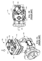
- Compressor 102 may be based on design of known "standard” Bendix BA-921® Compressor commercially available from Bendix Commercial Vehicle Systems LLC located in Elyria, Ohio.
- the known BA-921® compressor is shown in Figs. 2A and 2B , and is designated with reference numeral "202" in Figs. 2A and 2B.
- Fig. 2B is a top view, looking approximately in the direction of arrow "2B" shown in Fig. 2A .
- Compressor 202 includes compressor cylinder head assembly 204 disposed on compressor crankcase assembly 206 in known manner.
- Cylinder head assembly 204 includes air inlet port 207 through which air can be received for compression within the crankcase assembly 206 and cylinder head assembly 204.
- Cylinder head assembly 204 includes discharge port 208 through which compressed air can be delivered from the cylinder head assembly 204.
- a pair of coolant ports 210, 212 is provided through which coolant can flow to cool cylinder head assembly 204 as compressed air is being generated.
- Cylinder head assembly 204 further includes safety valve port 214, and governor port 216 which is connectable through a pneumatic control line to a governor.
- Known compressor 202 shown in Figs. 2A and 2B can be modified to provide a vehicle air compressor apparatus 100, such as shown in Fig. 1 .
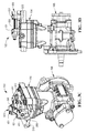
- FIG. 3A is a perspective view of compressor 102 shown in Fig. 1 .
- Fig. 3B is a top view, looking approximately in the direction of arrow "3B" shown in Fig. 3A , and showing certain parts removed so that parts of cylinder head assembly 104 ( Fig. 1 ) can be seen.
- Fig. 3C is a perspective view, looking approximately in the direction of arrow "3C” shown in Fig. 3A .
- Fig. 3D is a side view, looking approximately in the direction of arrow "3D” shown in Fig. 3A .
- compressor 102 includes cylinder head assembly 104 disposed on crankcase assembly 106.
- compressor 102 including cylinder head assembly 104 and crankcase 106 can be manufactured as a new compressor
- the known BA-921® compressor shown in Figs. 2A and 2B may be modified (i.e., retrofitted) to provide the structure and operation of compressor 102 shown in Figs. 3A, 3B , 3C, and 3D .
- Such a modification is briefly described in the next couple of paragraphs hereinbelow.
- crankcase assembly 106 shown in Fig. 1 has the same structure as legacy crankcase assembly 206 shown in Fig 2A .
- cylinder head assembly 104 shown in Figs. 3A, 3B , 3C, and 3D has a structure which is different from the structure of legacy cylinder head assembly 204 shown in Figs. 2A and 2B .
- compressor 102 shown in Figs. 3A, 3B , 3C, and 3D
- cylinder head assembly 104 includes air inlet port 307 through which air can be received for compression within crankcase assembly 106 and cylinder head assembly 104.
- Cylinder head assembly 104 also includes discharge port 308 ( Fig. 3C ) through which compressed air can be delivered from the cylinder head assembly 104.
- a pair of coolant ports 310, 312 is provided through which coolant can flow to cool cylinder head assembly 104 as compressed air is being generated.
- Cylinder head assembly 104 further includes governor port 316 ( Fig. 3C ) which is connectable through pneumatic control line 124 ( Fig. 1 ) to governor 120.
- cylinder head assembly 104 further includes first intermediate port 342 through which compressed air can pass, and second intermediate port 352 through which compressed air can pass.
- First intermediate port 342 is connectable in fluid communication to air inlet port 307 through a number of air passages which are internal to cylinder head assembly 104.
- Second intermediate port 352 is connectable in fluid communication to discharge port 308 through a number of air passages which are internal to cylinder head assembly 104.
- First cylinder head bearing surface 344 is located in the vicinity of first intermediate port 342, and first O-ring 348 is on first cylinder head bearing surface 344. Threaded bolt bores 346 are disposed on opposite sides of first intermediate port 342. Similarly, second cylinder head bearing surface 354 is located in the vicinity of second intermediate port 352, and second O-ring 358 is on second cylinder head bearing surface 354. Threaded bolt bores 356 are disposed on opposite sides of second intermediate port 352.
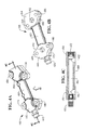
- discharge air cooling jumper 400 is illustrated.
- Fig. 4B is a bottom perspective view, looking approximately in the direction of arrow "4B" shown in Fig. 4A.
- Fig. 4C is a sectional view, taken approximately along line 4C-4C shown in Fig. 4A , and showing discharge air path 462 in discharge air cooling jumper 400.
- Discharge air cooling jumper 400 is connectable between first and second intermediate ports 342, 352 of cylinder head assembly 104 to cool compressed air passing therethrough, as will be described in detail herein.
- Discharge air cooling jumper 400 may comprise metal material which is the same or similar to material of cylinder head assembly 104.
- material of discharge air cooling jumper 400 may comprise aluminum.
- Material of discharge air cooling jumper 400 may comprise material other than metal material.
- Discharge air cooling jumper 400 includes first end portion 440, second end portion 450, and central portion 460 interconnecting first and second end portions 440, 450.
- First end portion 440 includes first port 442 located at one end of discharge air path 462.
- Second end portion 450 includes second port 452 located at opposite end of discharge air path 462. Accordingly, discharge air path 462 extends between first and second end ports 442, 452 to define a substantially U-shaped air path through jumper 400.
- Safety valve 470 is disposed at first end portion 440 of jumper 400. Machining hole plug 472 is disposed at second end portion 450 of jumper 400.
- First jumper bearing surface 444 is disposed at first end portion 440 of jumper 400, and is located in vicinity of first port 442.
- Bolt holes 446 are disposed on opposite sides of first port 442.
- second jumper bearing surface 454 is disposed at second end portion 450, and is located in vicinity of second port 452.
- Bolt holes 456 are disposed on opposite sides of second port 452.
- Discharge air cooling jumper 400 shown in Figs 4A, 4B, and 4C is connected to cylinder head assembly 104 using bolts 401 ( Figs 3A and 3C ).
- Bolts 401 pass through bolt holes 446, 456 of jumper 400, and are screwed into threaded bores 346, 356 ( Fig. 3B ) in cylinder head assembly 104.
- O-ring 348 is sandwiched between first cylinder head bearing surface 344 and first jumper bearing surface 444 to provide an airtight seal therebetween.
- O-ring 358 is sandwiched between second cylinder head bearing surface 354 and second jumper bearing surface 454 to provide an airtight seal therebetween.
- an air gap 320 (best shown in Fig. 3D ) is defined between central portion 460 of jumper 400 and cylinder head assembly 104.
- central portion 460 of jumper 400 is spaced apart from cylinder head assembly 104.
- jumper 400 The position of jumper 400 is located outside of cylinder head assembly 104, and is exposed to ambient air. As such, jumper 400 experiences temperatures less than temperatures experienced by cylinder head assembly 104. The result is that compressed air passing through jumper 400 is cooled.
- head-cooled discharge air exits cylinder head assembly 104 and enters into discharge air path 462 of discharge air cooling jumper 400. Since jumper 400 is located outside of cylinder head assembly 104 and is exposed to ambient air, the discharge air is cooled before it enters back into cylinder head assembly 104 to be delivered to discharge port 308 ( Fig. 3C ).
- a new compressor can be manufactured, or a legacy compressor can be modified to provide the additional cooling of air discharged from the compressor as described hereinabove.
- port locations of a cylinder head assembly of a commercially available vehicle air compressor i.e., the standard Bendix BA-921® Compressor in the above-described example
- a commercially available vehicle air compressor i.e., the standard Bendix BA-921® Compressor in the above-described example
- port locations of the BA-921® have been altered to facilitate installation of discharge air cooling jumper 400 to provide extra cooling of air discharged from the compressor. This is achieved without having to modify the compressor crankcase assembly.
- a number of advantages result by providing either a newly-manufactured compressor or a modified commercially available vehicle air compressor in accordance with the above-described description.
- One advantage is that the overall temperature of air discharged from the discharge port of the compressor is reduced. Engineering tests have indicated a 15% to 50% reduction in the temperature of the air at the discharge port when comparing a standard BA-921® compressor without a discharge air cooling jumper to the new compressor with the discharge air cooling jumper. This temperature reduction decreases the potential of carbon buildup at the discharge port.
- Another advantage is that compressed air is supplied at a more ideal temperature to downstream components. The result is improved operation of downstream components.
- discharge air cooling jumper 400 having a shape and configuration such as shown in Figs. 3A, 3B , 3C, and 3D
- discharge air cooling jumper may have a shape and configuration involving any combination of a set of fittings and a pipe, tubing, metal couplings, and the like.
- apparatus 100 being used in a heavy vehicle such as a truck, it is conceivable that apparatus 100 may be used in other types of heavy vehicles, such as busses for example.
- Discharge air cooling jumper 500 shown in Figs. 5A and 5B has similar construction as discharge air cooling jumper 400 shown in Figs. 4A and 4B .
- Jumper 500 further includes cooling fin or rib 580 disposed longitudinally on one side of central portion 560 of jumper 500. Cooling fin 580 provides more surface area exposed to ambient air to improve cooling effectiveness of jumper 500.
- Discharge air cooling jumper 600 shown in Figs. 6A and 6B has similar construction as discharge air cooling jumper 400 shown in Figs. 4A and 4B .
- Jumper 600 further includes cooling fin or rib 680 disposed longitudinally on one side of central portion 660 of jumper 600 and another cooling fin 682 disposed longitudinally on opposite side of central portion 660 of jumper 600. Cooling fins 680, 682 provide more surface area exposed to ambient air to improve cooling effectiveness of jumper 600.
- Discharge air cooling jumper 700 shown in Figs. 7A and 7B has similar construction as discharge air cooling jumper 400 shown in Figs. 4A and 4B .
- Jumper 700 further includes at least one cooling fin 784 disposed longitudinally on top side of central portion 760 of jumper 700.
- Jumper 700 also includes at least one cooling fin 786 disposed longitudinally on bottom side of central portion 760 of jumper 700. Cooling fins 784, 786 provide more surface area exposed to ambient air to improve cooling effectiveness of jumper 700.
- any number of cooling fins be disposed on top side of central portion 760, and that any number of cooling fins be disposed on bottom side of central portion 760. It is also conceivable that only cooling fins are disposed on top side without any cooling fins disposed on bottom side, or only cooling fins are disposed on bottom side without any cooling fins disposed on top side.
- Discharge air cooling jumper 800 shown in Figs. 8A and 8B has similar construction as discharge air cooling jumper 400 shown in Figs. 4A and 4B .
- Jumper 800 further includes at least one cooling fin or rib 888 disposed radially on central portion 860 of jumper 800. Radial cooling fin 888 provides more surface area exposed to ambient air to improve cooling effectiveness of jumper 800.
- cooling fins or ribs change the geometry of the jumper to improve cooling effectiveness of the jumper and thereby to provide extra cooling of compressed air traveling through the jumper.
- the number of cooling fins may be any combination of side fins, top fins, bottom fins, or radial fins.
Landscapes
- Engineering & Computer Science (AREA)
- Mechanical Engineering (AREA)
- General Engineering & Computer Science (AREA)
- Transportation (AREA)
- Compressor (AREA)
Applications Claiming Priority (1)
| Application Number | Priority Date | Filing Date | Title |
|---|---|---|---|
| US14/174,434 US20150219083A1 (en) | 2014-02-06 | 2014-02-06 | Vehicle Air Compressor Apparatus for a Heavy Vehicle Air Braking System |
Publications (2)
| Publication Number | Publication Date |
|---|---|
| EP2905191A1 true EP2905191A1 (de) | 2015-08-12 |
| EP2905191B1 EP2905191B1 (de) | 2019-07-17 |
Family
ID=52423652
Family Applications (1)
| Application Number | Title | Priority Date | Filing Date |
|---|---|---|---|
| EP15153171.2A Active EP2905191B1 (de) | 2014-02-06 | 2015-01-30 | Fahrzeugluftkompressorvorrichtung für ein Druckluftbremssystem für Schwerfahrzeuge |
Country Status (2)
| Country | Link |
|---|---|
| US (1) | US20150219083A1 (de) |
| EP (1) | EP2905191B1 (de) |
Cited By (1)
| Publication number | Priority date | Publication date | Assignee | Title |
|---|---|---|---|---|
| CN105276031A (zh) * | 2015-10-20 | 2016-01-27 | 浙江西田机械有限公司 | 无油空气压缩机一体式制动器 |
Families Citing this family (7)
| Publication number | Priority date | Publication date | Assignee | Title |
|---|---|---|---|---|
| US10379143B2 (en) | 2014-07-23 | 2019-08-13 | Cummins, Inc. | System and method for improving a battery management and accumulator system |
| CN106573530B (zh) | 2014-08-26 | 2018-08-03 | 康明斯有限公司 | 电动发动机附件控制 |
| EP3966511B1 (de) | 2019-02-06 | 2025-10-08 | Jeffrey A. Weston | Hydronisches system und betriebsverfahren |
| US11333140B2 (en) * | 2019-06-11 | 2022-05-17 | Caterpillar Inc. | Cooling block for multi-cylinder air compressor |
| US20240149856A1 (en) * | 2022-11-07 | 2024-05-09 | Bendix Commercial Vehicle Systems Llc | Redundant governor apparatus for a vehicle air brake charging system |
| CN116146461B (zh) * | 2023-02-28 | 2025-06-03 | 采埃孚商用车系统(青岛)有限公司 | 空气压缩机缸头和空气压缩机 |
| CN224017370U (zh) * | 2024-03-14 | 2026-03-20 | 精达科技(安徽)有限公司 | 一种乘用车集成系统 |
Citations (11)
| Publication number | Priority date | Publication date | Assignee | Title |
|---|---|---|---|---|
| GB1357078A (en) * | 1972-11-21 | 1974-06-19 | Lapco Warehousing Mfg Ltd | Aftercooler having an extruded aluminium casing |
| DE2410705A1 (de) * | 1974-03-06 | 1975-09-18 | Knorr Bremse Gmbh | Kompressor |
| DE2422448A1 (de) * | 1974-05-09 | 1975-11-13 | Knorr Bremse Gmbh | Kompakte anordnung einer luftpressereinheit mit dem antriebsaggregat |
| FR2449211A1 (fr) * | 1979-02-15 | 1980-09-12 | Wabco Fahrzeugbremsen Gmbh | Culasse de compresseur d'air a plusieurs etages |
| DE19535079A1 (de) * | 1994-10-13 | 1996-04-18 | Wabco Gmbh | Verdichter |
| JPH11218079A (ja) * | 1998-01-30 | 1999-08-10 | Sanwa Seiki Co Ltd | エアコンプレッサ |
| US6062825A (en) * | 1998-01-21 | 2000-05-16 | Chovan; Dale A. | Air compressor aftercooler with automatic heated drain valve and start-up shut-off |
| WO2006057667A2 (en) * | 2004-11-29 | 2006-06-01 | Haldex Brake Corporation | Compressor with fortified piston channel |
| DE102008018467A1 (de) * | 2008-04-11 | 2009-10-15 | Knorr-Bremse Systeme für Nutzfahrzeuge GmbH | Ventilplatte für einen Kompressor und Verfahren zur Kühlung komprimierter Luft in einer Ventilplatte eines Kompressors |
| DE102010024346A1 (de) * | 2010-06-18 | 2011-12-22 | Knorr-Bremse Systeme für Schienenfahrzeuge GmbH | Luftgekühlter Kolbenkompressor mit spezieller Kühlluftführung |
| AT512923A4 (de) * | 2013-01-25 | 2013-12-15 | Hoerbiger Kompressortech Hold | Zylinderkopf für zweistufigen Hubkolbenverdichter |
Family Cites Families (2)
| Publication number | Priority date | Publication date | Assignee | Title |
|---|---|---|---|---|
| US6183211B1 (en) * | 1999-02-09 | 2001-02-06 | Devilbiss Air Power Company | Two stage oil free air compressor |
| US7422422B2 (en) * | 2004-08-24 | 2008-09-09 | Tecumseh Products Company | Compressor assembly with pressure relief valve fittings |
-
2014
- 2014-02-06 US US14/174,434 patent/US20150219083A1/en not_active Abandoned
-
2015
- 2015-01-30 EP EP15153171.2A patent/EP2905191B1/de active Active
Patent Citations (11)
| Publication number | Priority date | Publication date | Assignee | Title |
|---|---|---|---|---|
| GB1357078A (en) * | 1972-11-21 | 1974-06-19 | Lapco Warehousing Mfg Ltd | Aftercooler having an extruded aluminium casing |
| DE2410705A1 (de) * | 1974-03-06 | 1975-09-18 | Knorr Bremse Gmbh | Kompressor |
| DE2422448A1 (de) * | 1974-05-09 | 1975-11-13 | Knorr Bremse Gmbh | Kompakte anordnung einer luftpressereinheit mit dem antriebsaggregat |
| FR2449211A1 (fr) * | 1979-02-15 | 1980-09-12 | Wabco Fahrzeugbremsen Gmbh | Culasse de compresseur d'air a plusieurs etages |
| DE19535079A1 (de) * | 1994-10-13 | 1996-04-18 | Wabco Gmbh | Verdichter |
| US6062825A (en) * | 1998-01-21 | 2000-05-16 | Chovan; Dale A. | Air compressor aftercooler with automatic heated drain valve and start-up shut-off |
| JPH11218079A (ja) * | 1998-01-30 | 1999-08-10 | Sanwa Seiki Co Ltd | エアコンプレッサ |
| WO2006057667A2 (en) * | 2004-11-29 | 2006-06-01 | Haldex Brake Corporation | Compressor with fortified piston channel |
| DE102008018467A1 (de) * | 2008-04-11 | 2009-10-15 | Knorr-Bremse Systeme für Nutzfahrzeuge GmbH | Ventilplatte für einen Kompressor und Verfahren zur Kühlung komprimierter Luft in einer Ventilplatte eines Kompressors |
| DE102010024346A1 (de) * | 2010-06-18 | 2011-12-22 | Knorr-Bremse Systeme für Schienenfahrzeuge GmbH | Luftgekühlter Kolbenkompressor mit spezieller Kühlluftführung |
| AT512923A4 (de) * | 2013-01-25 | 2013-12-15 | Hoerbiger Kompressortech Hold | Zylinderkopf für zweistufigen Hubkolbenverdichter |
Cited By (1)
| Publication number | Priority date | Publication date | Assignee | Title |
|---|---|---|---|---|
| CN105276031A (zh) * | 2015-10-20 | 2016-01-27 | 浙江西田机械有限公司 | 无油空气压缩机一体式制动器 |
Also Published As
| Publication number | Publication date |
|---|---|
| US20150219083A1 (en) | 2015-08-06 |
| EP2905191B1 (de) | 2019-07-17 |
Similar Documents
| Publication | Publication Date | Title |
|---|---|---|
| EP2905191A1 (de) | Fahrzeugluftkompressorvorrichtung für ein Druckluftbremssystem für Schwerfahrzeuge | |
| US9657733B2 (en) | Compressor for a vehicle air supply system | |
| US11365670B2 (en) | Method of modifying an engine oil cooling system | |
| US8337177B2 (en) | Valve plate for a compressor, and method for cooling compressed air in a valve plate of a compressor | |
| US9658001B2 (en) | Stuffing box cooling system | |
| CN104454461A (zh) | 具有热激活性热交换器的压缩机系统 | |
| US9951762B2 (en) | Compressor with crankshaft and insert | |
| EP3895992B1 (de) | Luftkreislaufmaschinenmodulluftgatterdichtung für klimaregelungssysteme | |
| CN101331319B (zh) | 水冷却的活塞式压气机 | |
| CN105857618A (zh) | 利用并联冲压式热交换器的环境控制系统 | |
| US20150204323A1 (en) | Compressor Cylinder Head for a Compressor, Vehicle Therewith and Method for Cooling and Producing Such a Compressor Cylinder Head | |
| SE541131C2 (sv) | Avluftningskrets för ett kylsystem vid en förbränningsmotor | |
| US10920628B2 (en) | Cooling assembly for a filter head of an engine | |
| US9556872B2 (en) | Gas compressor formed with a high-pressure supply hole | |
| CN106662095A (zh) | 用于压缩机的完全集成的缸盖 | |
| TWI527684B (zh) | 空氣壓縮系統及其冷卻結構 | |
| CN107667239B (zh) | 用于空气压缩机的卸载阀的活塞组件 | |
| CN103835921A (zh) | 一种自润滑高效油冷空气压缩机 | |
| CN206968636U (zh) | 一种制动鼓风冷装置 | |
| US9651040B2 (en) | Unloader valve apparatus for an air compressor | |
| US9920763B2 (en) | Contact cooled rotary airend injection spray insert | |
| EP3359816B1 (de) | Geschlossener trockenkolben-bahnkompressor mit schalldämmendem schutzgehäuse | |
| KR20140010053A (ko) | 매니폴드 이음부 밀봉체 | |
| US7621251B1 (en) | Lubrication cooling system for a vehicle | |
| CN110594320B (zh) | 一种带驻车制动的湿式制动器 |
Legal Events
| Date | Code | Title | Description |
|---|---|---|---|
| PUAI | Public reference made under article 153(3) epc to a published international application that has entered the european phase |
Free format text: ORIGINAL CODE: 0009012 |
|
| AK | Designated contracting states |
Kind code of ref document: A1 Designated state(s): AL AT BE BG CH CY CZ DE DK EE ES FI FR GB GR HR HU IE IS IT LI LT LU LV MC MK MT NL NO PL PT RO RS SE SI SK SM TR |
|
| AX | Request for extension of the european patent |
Extension state: BA ME |
|
| 17P | Request for examination filed |
Effective date: 20160128 |
|
| RBV | Designated contracting states (corrected) |
Designated state(s): AL AT BE BG CH CY CZ DE DK EE ES FI FR GB GR HR HU IE IS IT LI LT LU LV MC MK MT NL NO PL PT RO RS SE SI SK SM TR |
|
| STAA | Information on the status of an ep patent application or granted ep patent |
Free format text: STATUS: EXAMINATION IS IN PROGRESS |
|
| 17Q | First examination report despatched |
Effective date: 20181016 |
|
| GRAP | Despatch of communication of intention to grant a patent |
Free format text: ORIGINAL CODE: EPIDOSNIGR1 |
|
| STAA | Information on the status of an ep patent application or granted ep patent |
Free format text: STATUS: GRANT OF PATENT IS INTENDED |
|
| INTG | Intention to grant announced |
Effective date: 20190307 |
|
| GRAS | Grant fee paid |
Free format text: ORIGINAL CODE: EPIDOSNIGR3 |
|
| GRAA | (expected) grant |
Free format text: ORIGINAL CODE: 0009210 |
|
| STAA | Information on the status of an ep patent application or granted ep patent |
Free format text: STATUS: THE PATENT HAS BEEN GRANTED |
|
| AK | Designated contracting states |
Kind code of ref document: B1 Designated state(s): AL AT BE BG CH CY CZ DE DK EE ES FI FR GB GR HR HU IE IS IT LI LT LU LV MC MK MT NL NO PL PT RO RS SE SI SK SM TR |
|
| REG | Reference to a national code |
Ref country code: GB Ref legal event code: FG4D |
|
| REG | Reference to a national code |
Ref country code: CH Ref legal event code: EP |
|
| REG | Reference to a national code |
Ref country code: IE Ref legal event code: FG4D |
|
| REG | Reference to a national code |
Ref country code: DE Ref legal event code: R096 Ref document number: 602015033798 Country of ref document: DE |
|
| REG | Reference to a national code |
Ref country code: AT Ref legal event code: REF Ref document number: 1155579 Country of ref document: AT Kind code of ref document: T Effective date: 20190815 |
|
| REG | Reference to a national code |
Ref country code: SE Ref legal event code: TRGR |
|
| REG | Reference to a national code |
Ref country code: NL Ref legal event code: FP |
|
| REG | Reference to a national code |
Ref country code: LT Ref legal event code: MG4D |
|
| REG | Reference to a national code |
Ref country code: AT Ref legal event code: MK05 Ref document number: 1155579 Country of ref document: AT Kind code of ref document: T Effective date: 20190717 |
|
| PG25 | Lapsed in a contracting state [announced via postgrant information from national office to epo] |
Ref country code: LT Free format text: LAPSE BECAUSE OF FAILURE TO SUBMIT A TRANSLATION OF THE DESCRIPTION OR TO PAY THE FEE WITHIN THE PRESCRIBED TIME-LIMIT Effective date: 20190717 Ref country code: HR Free format text: LAPSE BECAUSE OF FAILURE TO SUBMIT A TRANSLATION OF THE DESCRIPTION OR TO PAY THE FEE WITHIN THE PRESCRIBED TIME-LIMIT Effective date: 20190717 Ref country code: AT Free format text: LAPSE BECAUSE OF FAILURE TO SUBMIT A TRANSLATION OF THE DESCRIPTION OR TO PAY THE FEE WITHIN THE PRESCRIBED TIME-LIMIT Effective date: 20190717 Ref country code: BG Free format text: LAPSE BECAUSE OF FAILURE TO SUBMIT A TRANSLATION OF THE DESCRIPTION OR TO PAY THE FEE WITHIN THE PRESCRIBED TIME-LIMIT Effective date: 20191017 Ref country code: PT Free format text: LAPSE BECAUSE OF FAILURE TO SUBMIT A TRANSLATION OF THE DESCRIPTION OR TO PAY THE FEE WITHIN THE PRESCRIBED TIME-LIMIT Effective date: 20191118 Ref country code: NO Free format text: LAPSE BECAUSE OF FAILURE TO SUBMIT A TRANSLATION OF THE DESCRIPTION OR TO PAY THE FEE WITHIN THE PRESCRIBED TIME-LIMIT Effective date: 20191017 Ref country code: FI Free format text: LAPSE BECAUSE OF FAILURE TO SUBMIT A TRANSLATION OF THE DESCRIPTION OR TO PAY THE FEE WITHIN THE PRESCRIBED TIME-LIMIT Effective date: 20190717 |
|
| PG25 | Lapsed in a contracting state [announced via postgrant information from national office to epo] |
Ref country code: RS Free format text: LAPSE BECAUSE OF FAILURE TO SUBMIT A TRANSLATION OF THE DESCRIPTION OR TO PAY THE FEE WITHIN THE PRESCRIBED TIME-LIMIT Effective date: 20190717 Ref country code: IS Free format text: LAPSE BECAUSE OF FAILURE TO SUBMIT A TRANSLATION OF THE DESCRIPTION OR TO PAY THE FEE WITHIN THE PRESCRIBED TIME-LIMIT Effective date: 20191117 Ref country code: GR Free format text: LAPSE BECAUSE OF FAILURE TO SUBMIT A TRANSLATION OF THE DESCRIPTION OR TO PAY THE FEE WITHIN THE PRESCRIBED TIME-LIMIT Effective date: 20191018 Ref country code: ES Free format text: LAPSE BECAUSE OF FAILURE TO SUBMIT A TRANSLATION OF THE DESCRIPTION OR TO PAY THE FEE WITHIN THE PRESCRIBED TIME-LIMIT Effective date: 20190717 Ref country code: LV Free format text: LAPSE BECAUSE OF FAILURE TO SUBMIT A TRANSLATION OF THE DESCRIPTION OR TO PAY THE FEE WITHIN THE PRESCRIBED TIME-LIMIT Effective date: 20190717 Ref country code: AL Free format text: LAPSE BECAUSE OF FAILURE TO SUBMIT A TRANSLATION OF THE DESCRIPTION OR TO PAY THE FEE WITHIN THE PRESCRIBED TIME-LIMIT Effective date: 20190717 |
|
| PG25 | Lapsed in a contracting state [announced via postgrant information from national office to epo] |
Ref country code: TR Free format text: LAPSE BECAUSE OF FAILURE TO SUBMIT A TRANSLATION OF THE DESCRIPTION OR TO PAY THE FEE WITHIN THE PRESCRIBED TIME-LIMIT Effective date: 20190717 |
|
| PG25 | Lapsed in a contracting state [announced via postgrant information from national office to epo] |
Ref country code: DK Free format text: LAPSE BECAUSE OF FAILURE TO SUBMIT A TRANSLATION OF THE DESCRIPTION OR TO PAY THE FEE WITHIN THE PRESCRIBED TIME-LIMIT Effective date: 20190717 Ref country code: EE Free format text: LAPSE BECAUSE OF FAILURE TO SUBMIT A TRANSLATION OF THE DESCRIPTION OR TO PAY THE FEE WITHIN THE PRESCRIBED TIME-LIMIT Effective date: 20190717 Ref country code: RO Free format text: LAPSE BECAUSE OF FAILURE TO SUBMIT A TRANSLATION OF THE DESCRIPTION OR TO PAY THE FEE WITHIN THE PRESCRIBED TIME-LIMIT Effective date: 20190717 Ref country code: PL Free format text: LAPSE BECAUSE OF FAILURE TO SUBMIT A TRANSLATION OF THE DESCRIPTION OR TO PAY THE FEE WITHIN THE PRESCRIBED TIME-LIMIT Effective date: 20190717 |
|
| PG25 | Lapsed in a contracting state [announced via postgrant information from national office to epo] |
Ref country code: SM Free format text: LAPSE BECAUSE OF FAILURE TO SUBMIT A TRANSLATION OF THE DESCRIPTION OR TO PAY THE FEE WITHIN THE PRESCRIBED TIME-LIMIT Effective date: 20190717 Ref country code: SK Free format text: LAPSE BECAUSE OF FAILURE TO SUBMIT A TRANSLATION OF THE DESCRIPTION OR TO PAY THE FEE WITHIN THE PRESCRIBED TIME-LIMIT Effective date: 20190717 Ref country code: CZ Free format text: LAPSE BECAUSE OF FAILURE TO SUBMIT A TRANSLATION OF THE DESCRIPTION OR TO PAY THE FEE WITHIN THE PRESCRIBED TIME-LIMIT Effective date: 20190717 Ref country code: IS Free format text: LAPSE BECAUSE OF FAILURE TO SUBMIT A TRANSLATION OF THE DESCRIPTION OR TO PAY THE FEE WITHIN THE PRESCRIBED TIME-LIMIT Effective date: 20200224 |
|
| REG | Reference to a national code |
Ref country code: DE Ref legal event code: R097 Ref document number: 602015033798 Country of ref document: DE |
|
| PLBE | No opposition filed within time limit |
Free format text: ORIGINAL CODE: 0009261 |
|
| STAA | Information on the status of an ep patent application or granted ep patent |
Free format text: STATUS: NO OPPOSITION FILED WITHIN TIME LIMIT |
|
| PG2D | Information on lapse in contracting state deleted |
Ref country code: IS |
|
| 26N | No opposition filed |
Effective date: 20200603 |
|
| PG25 | Lapsed in a contracting state [announced via postgrant information from national office to epo] |
Ref country code: SI Free format text: LAPSE BECAUSE OF FAILURE TO SUBMIT A TRANSLATION OF THE DESCRIPTION OR TO PAY THE FEE WITHIN THE PRESCRIBED TIME-LIMIT Effective date: 20190717 Ref country code: MC Free format text: LAPSE BECAUSE OF FAILURE TO SUBMIT A TRANSLATION OF THE DESCRIPTION OR TO PAY THE FEE WITHIN THE PRESCRIBED TIME-LIMIT Effective date: 20190717 |
|
| REG | Reference to a national code |
Ref country code: CH Ref legal event code: PL |
|
| GBPC | Gb: european patent ceased through non-payment of renewal fee |
Effective date: 20200130 |
|
| REG | Reference to a national code |
Ref country code: BE Ref legal event code: MM Effective date: 20200131 |
|
| PG25 | Lapsed in a contracting state [announced via postgrant information from national office to epo] |
Ref country code: GB Free format text: LAPSE BECAUSE OF NON-PAYMENT OF DUE FEES Effective date: 20200130 Ref country code: LU Free format text: LAPSE BECAUSE OF NON-PAYMENT OF DUE FEES Effective date: 20200130 |
|
| PG25 | Lapsed in a contracting state [announced via postgrant information from national office to epo] |
Ref country code: CH Free format text: LAPSE BECAUSE OF NON-PAYMENT OF DUE FEES Effective date: 20200131 Ref country code: LI Free format text: LAPSE BECAUSE OF NON-PAYMENT OF DUE FEES Effective date: 20200131 Ref country code: BE Free format text: LAPSE BECAUSE OF NON-PAYMENT OF DUE FEES Effective date: 20200131 |
|
| PG25 | Lapsed in a contracting state [announced via postgrant information from national office to epo] |
Ref country code: IE Free format text: LAPSE BECAUSE OF NON-PAYMENT OF DUE FEES Effective date: 20200130 |
|
| PGFP | Annual fee paid to national office [announced via postgrant information from national office to epo] |
Ref country code: FR Payment date: 20210122 Year of fee payment: 7 Ref country code: IT Payment date: 20210121 Year of fee payment: 7 Ref country code: NL Payment date: 20210120 Year of fee payment: 7 |
|
| PGFP | Annual fee paid to national office [announced via postgrant information from national office to epo] |
Ref country code: DE Payment date: 20210120 Year of fee payment: 7 Ref country code: SE Payment date: 20210120 Year of fee payment: 7 |
|
| PG25 | Lapsed in a contracting state [announced via postgrant information from national office to epo] |
Ref country code: MT Free format text: LAPSE BECAUSE OF FAILURE TO SUBMIT A TRANSLATION OF THE DESCRIPTION OR TO PAY THE FEE WITHIN THE PRESCRIBED TIME-LIMIT Effective date: 20190717 Ref country code: CY Free format text: LAPSE BECAUSE OF FAILURE TO SUBMIT A TRANSLATION OF THE DESCRIPTION OR TO PAY THE FEE WITHIN THE PRESCRIBED TIME-LIMIT Effective date: 20190717 |
|
| PG25 | Lapsed in a contracting state [announced via postgrant information from national office to epo] |
Ref country code: MK Free format text: LAPSE BECAUSE OF FAILURE TO SUBMIT A TRANSLATION OF THE DESCRIPTION OR TO PAY THE FEE WITHIN THE PRESCRIBED TIME-LIMIT Effective date: 20190717 |
|
| REG | Reference to a national code |
Ref country code: DE Ref legal event code: R119 Ref document number: 602015033798 Country of ref document: DE |
|
| REG | Reference to a national code |
Ref country code: SE Ref legal event code: EUG |
|
| REG | Reference to a national code |
Ref country code: NL Ref legal event code: MM Effective date: 20220201 |
|
| PG25 | Lapsed in a contracting state [announced via postgrant information from national office to epo] |
Ref country code: SE Free format text: LAPSE BECAUSE OF NON-PAYMENT OF DUE FEES Effective date: 20220131 Ref country code: NL Free format text: LAPSE BECAUSE OF NON-PAYMENT OF DUE FEES Effective date: 20220201 Ref country code: DE Free format text: LAPSE BECAUSE OF NON-PAYMENT OF DUE FEES Effective date: 20220802 |
|
| PG25 | Lapsed in a contracting state [announced via postgrant information from national office to epo] |
Ref country code: FR Free format text: LAPSE BECAUSE OF NON-PAYMENT OF DUE FEES Effective date: 20220131 |
|
| PG25 | Lapsed in a contracting state [announced via postgrant information from national office to epo] |
Ref country code: IT Free format text: LAPSE BECAUSE OF NON-PAYMENT OF DUE FEES Effective date: 20220130 |
|
| P01 | Opt-out of the competence of the unified patent court (upc) registered |
Effective date: 20230508 |