EP2905211B1 - Frein hydraulique sur jante - Google Patents
Frein hydraulique sur jante Download PDFInfo
- Publication number
- EP2905211B1 EP2905211B1 EP15000831.6A EP15000831A EP2905211B1 EP 2905211 B1 EP2905211 B1 EP 2905211B1 EP 15000831 A EP15000831 A EP 15000831A EP 2905211 B1 EP2905211 B1 EP 2905211B1
- Authority
- EP
- European Patent Office
- Prior art keywords
- brake
- adjust
- arm
- piston
- hydraulic
- Prior art date
- Legal status (The legal status is an assumption and is not a legal conclusion. Google has not performed a legal analysis and makes no representation as to the accuracy of the status listed.)
- Not-in-force
Links
Images










Classifications
-
- B—PERFORMING OPERATIONS; TRANSPORTING
- B62—LAND VEHICLES FOR TRAVELLING OTHERWISE THAN ON RAILS
- B62L—BRAKES SPECIALLY ADAPTED FOR CYCLES
- B62L1/00—Brakes; Arrangements thereof
- B62L1/02—Brakes; Arrangements thereof in which cycle wheels are engaged by brake elements
- B62L1/06—Brakes; Arrangements thereof in which cycle wheels are engaged by brake elements the wheel rim being engaged
- B62L1/10—Brakes; Arrangements thereof in which cycle wheels are engaged by brake elements the wheel rim being engaged by the elements moving substantially parallel to the wheel axis
- B62L1/12—Brakes; Arrangements thereof in which cycle wheels are engaged by brake elements the wheel rim being engaged by the elements moving substantially parallel to the wheel axis the elements being mounted on levers pivotable about a common axis
-
- B—PERFORMING OPERATIONS; TRANSPORTING
- B60—VEHICLES IN GENERAL
- B60T—VEHICLE BRAKE CONTROL SYSTEMS OR PARTS THEREOF; BRAKE CONTROL SYSTEMS OR PARTS THEREOF, IN GENERAL; ARRANGEMENT OF BRAKING ELEMENTS ON VEHICLES IN GENERAL; PORTABLE DEVICES FOR PREVENTING UNWANTED MOVEMENT OF VEHICLES; VEHICLE MODIFICATIONS TO FACILITATE COOLING OF BRAKES
- B60T1/00—Arrangements of braking elements, i.e. of those parts where braking effect occurs specially for vehicles
- B60T1/02—Arrangements of braking elements, i.e. of those parts where braking effect occurs specially for vehicles acting by retarding wheels
- B60T1/06—Arrangements of braking elements, i.e. of those parts where braking effect occurs specially for vehicles acting by retarding wheels acting otherwise than on tread, e.g. employing rim, drum, disc, or transmission or on double wheels
-
- F—MECHANICAL ENGINEERING; LIGHTING; HEATING; WEAPONS; BLASTING
- F16—ENGINEERING ELEMENTS AND UNITS; GENERAL MEASURES FOR PRODUCING AND MAINTAINING EFFECTIVE FUNCTIONING OF MACHINES OR INSTALLATIONS; THERMAL INSULATION IN GENERAL
- F16D—COUPLINGS FOR TRANSMITTING ROTATION; CLUTCHES; BRAKES
- F16D65/00—Parts or details
- F16D65/14—Actuating mechanisms for brakes; Means for initiating operation at a predetermined position
- F16D65/16—Actuating mechanisms for brakes; Means for initiating operation at a predetermined position arranged in or on the brake
- F16D65/18—Actuating mechanisms for brakes; Means for initiating operation at a predetermined position arranged in or on the brake adapted for drawing members together, e.g. for disc brakes
-
- F—MECHANICAL ENGINEERING; LIGHTING; HEATING; WEAPONS; BLASTING
- F16—ENGINEERING ELEMENTS AND UNITS; GENERAL MEASURES FOR PRODUCING AND MAINTAINING EFFECTIVE FUNCTIONING OF MACHINES OR INSTALLATIONS; THERMAL INSULATION IN GENERAL
- F16D—COUPLINGS FOR TRANSMITTING ROTATION; CLUTCHES; BRAKES
- F16D2121/00—Type of actuator operation force
- F16D2121/02—Fluid pressure
- F16D2121/04—Fluid pressure acting on a piston-type actuator, e.g. for liquid pressure
Definitions
- This invention relates to brake systems, and more particularly, to a hydraulic rim brake, preferably for a bicycle.
- Hydraulic rim brakes While there are some examples of hydraulically actuated rim brakes for bicycles, hydraulic brake systems for bicycles have been more successful when used to actuate disc brakes with calipers. Hydraulic rim brakes marketed to date tend to be complex and heavy, but have found some success in the comfort bike and urban bike market, where light weight is not a primary concern.
- hydraulic rim brakes might be preferred over cable actuated brakes is the increase in braking power that can be generated and the numerous routing options of the hydraulic tubing.
- the invention provides a bicycle with a hydraulic rim brake that is not heavy or complex and has suitable performance characteristics.
- US 3 338 337 A on which the preamble of claim 1 is based, discloses a brake unit comprising a first cylinder, a lever, brake arms, a second cylinder and a piston rod.
- the second cylinder is provided with a fixed extension that is pivotally connected to the end portion of one of the arms.
- FR 868 090 A discloses a hydraulic brake for a bicycle comprising two arms pivotally arranged about a pivot, a hydraulic piston with a movable piston.
- the piston is pivotally arranged with respect to the arm.
- US 3,899,056 discloses a brake assembly having first and second arms.
- the arms include second ends that are of substantial thickness and have sockets formed therein.
- a tensioned spring extends between the second arm end portions .
- a hydraulic cylinder is provided that is in communication with a tube, with the cylinder having a piston mounted therein from which a piston rod extends outwardly through a first end of the cylinder to engage a first socket 80.
- GB 745,061 discloses a fluid pressure brake within cylindrical projections of a housing, which are arranged at either sides of the expansible member, pistons the inner faces thereof present a concavity corresponding with the convexity of said expansible member, and their other faces carry studs contacting the ends of sliding members loosely mounted in holes formed in cap members of the cylindrical projections.
- Each of the sliding members has a screw-threaded bore into which are screwed adjusting screws and formed with limiting flanges for adjusting and centering the brake shoe-carrying levers d, and said screws are formed in the outer face of their heads with grooves for accommodating the upper end of said levers d, in order to maintain these ends constantly in contact with said screws under the influence of a helical tension spring connected at its ends to the levers.
- JP 2011143764 discloses a brake comprising a brake body including a pair of arm members.
- An urging member urges a pair of the arm members in the separating direction of the brake shoes from the rim.
- the brake force generation part includes a mechanism arranged between the pair of the arm members to extend and contract freely, and presses the pair of the arm members when it is extended to bring the pair of the brake shoes into pressure contact with the rim.
- One aspect of the invention provides a hydraulic brake assembly for a bicycle, the bicycle including a master cylinder operated by a brake lever, the hydraulic brake assembly including a first brake arm and a second brake arm, wherein the first and the second arm are pivotally connected to a frame member of the bicycle on a common pivot.
- the cylinder is in fluid communication with the master cylinder, wherein the cylinder is formed in one of the first and second brake arms.
- a piston is slidably disposed in the cylinder and configured such that movement of the piston in response to fluid displacement in the hydraulic brake assembly causes the first brake arm and the second brake arm to pivot.
- a link member may be configured to be responsive to movements of the piston such that movement of the piston is conveyed by the link member to the other of the first and second brake arms.
- the link member may be part of the other of the first and second brake arms.
- the hydraulic brake may further include an adjust mechanism configured to act upon the link member to adjust the spacing between the first and second brake arms.
- the hydraulic brake assembly may provide a link member having a first end in contact with the piston and a second end opposite the first end in contact with the other of the first and the second brake arms, the second end having a head.
- the adjust mechanism may include an adjust knob engaged with and displacing the link member second end to adjust the spacing between the first and second brake arms.
- the adjust knob may have an internal configuration shaped to engage the head of the link member.
- the adjust mechanism may include a spring positioned between the adjust knob and the head of the link member.
- the adjust mechanism may include a detent block having an first (axial) through bore through which a cylindrical boss portion of the receiver is positioned and a second (transverse) hole through which the link member is received, the detent block having one or more projections positioned and shaped to cooperate with corresponding features on the adjust knob.
- the hydraulic brake assembly may include a receiver disposed in the other of the first and second brake arms wherein the link member is engaged with the receiver.
- the link member may be threadably engaged with the receiver.
- the adjust knob may cause the link member to displace the receiver through action of the threaded engagement.
- the hydraulic brake assembly may further comprise a quick-release mechanism configured to act upon the link member to adjust the spacing between the first and second brake arms.
- the quick-release mechanism may include a quick-release lever positioned on the other of the first and second brake arms, the quick-release lever operatively displacing the link member.
- the receiver may be displaceable by the quick-release mechanism, the receiver being disposed in the other of the first and second brake arms wherein the link member is engaged with the receiver.
- the receiver may be disposed in a lever bore formed off center through the quick-release lever such that the quick-release lever imparts a cam action to the receiver when the quick-release lever is rotated.
- the first brake arm and the second brake arm may share a common pivot.
- the hydraulic brake assembly may include a return spring positioned to bias the first brake arm and the second brake arm apart.
- the fluid communication between the cylinder and the master cylinder may include a fluid passageway formed in the one of the first and second brake arms.
- One of the first and second brake arms may include a bleed port formed in communication with the fluid passageway to permit the release of fluid from the fluid passageway.
- the other of the first and second brake arms may include an upper end having a fork arrangement and wherein a combined adjust mechanism and a quick-release mechanism are disposed at the fork arrangement.
- the invention generally includes a brake assembly 50, with a first brake pad assembly 4 and a second brake pad assembly 5 secured to first brake arm 2 and second brake arm 3, respectively, in a manner that is well known in the art.
- a return spring 11 biases first brake pad assembly 4 and second brake pad assembly 5 apart from each other as shown in FIG. 4 by acting on the first and second brake arms 2, 3.
- Hydraulic fluid entering the brake assembly 50 from line 8 causes the first brake pad assembly 4 and second brake pad assembly 5 to draw together and conversely, permits the spring 11 to urge the first and second brake arms, and thus the brake pad assemblies 4, 5 apart when fluid leaves the brake assembly.
- brake assembly 50 is attachable to a bicycle frame member 10.
- the bicycle frame member 10 can be, for example, either a bicycle seat stay in the case of a rear brake, or a bicycle fork in the case of a front brake or an immobile part attached to the bicycle frame.
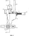
- Pivot bolt 1 is insertable into a hole 1a in bicycle frame member 10.
- Mounting nut 9 is inserted into this same hole 1a from the opposite side, and threadably engages pivot bolt 1.
- Mounting nut 9 is tightened until the head of mounting nut 9 is fully seated in a counter bore 1b in the hole 1a in bicycle frame member 10 and serrated washer 14 is tightly pressed against the surface of bicycle frame member 10 as shown in FIG. 2 .
- pivot bolt 1 is non-rotatable relative to bicycle frame member 10. It will be understood that other mounting arrangements are contemplated by the invention, for example a mounting arrangement with dual or multiple pivot points.
- brake assembly 50 may be constructed as follows. Referring to FIGS. 1 and 5 , thrust washer 19 is rotatable relative to pivot bolt 1. Bearing 21 is rotatably received in a hole 21a in first brake arm 2, and is rotatable relative to pivot bolt 1. Thrust washers 18 are rotatable relative to each other and relative to pivot bolt 1. Bearing 20 is rotatably received in a hole 20a in second brake arm 3, and is rotatable relative to pivot bolt 1. Thrust washers 17 are rotatable relative to each other and relative to pivot bolt 1.
- Nut 16 is threadably engaged with pivot bolt 1, and is axially positioned such that there is little to no axial play between nut 16, thrust washers 17, second brake arm 3, thrust washers 18, first brake arm 2, thrust washer 19, and the head of pivot bolt 1.
- Jam nut 15 is threadably engaged with pivot bolt 1, and is tightened securely against nut 16. After tightening, jam nut 15, nut 16 and pivot bolt 1 are fixed (i.e. non-rotatable) relative to each other.
- Serrated washer 14 is rotatable relative to pivot bolt 1.
- the middle portion of return spring 11 engages a slot in nut 16. This middle portion of return spring 11 cannot rotate relative to nut 16, and therefore cannot rotate relative to pivot bolt 1. Since pivot bolt 1 is non-rotatable relative to bicycle frame member 10, the middle portion of return spring 11 is also non-rotatable relative to bicycle frame member 10.
- the two ends of return spring 11 are slidably engaged with spring leg holders 12 and 13, respectively, and spring leg holders 12 and 13 are received in holes in second brake arm 3 and first brake arm 2, respectively, in a manner that is well known in the art.
- Return spring 11 urges spring leg holder 12 and second brake arm 3 to rotate clockwise around pivot bolt 1 in FIG. 4
- return spring 11 urges spring leg holder 13 and first brake arm 2 to rotate counterclockwise around pivot bolt 1 as shown in FIG. 4 .
- FIGS. 7a and 7b show a rear view and a side view of quick-release lever 6, which forms part of and actuates a quick-release mechanism 94 ( FIG. 17 ) of the brake assembly 50.
- Quick-release lever 6 has a cylindrical boss 6a, and a through bore 6b, which will also be referred to as a lever bore, that is not concentric with cylindrical boss 6a.
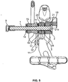
- FIG. 6 is a cross-sectional view of section B-B in FIG. 1 . Referring to FIG. 6 , cylindrical boss 6a of quick-release lever 6 is rotatably received in a hole 6c in first brake arm 2. Receiver 23 is rotatably received in bore 6b of quick-release lever 6. Referring to FIGS.
- distal end of receiver 23 is rotatably received in through bore or first hole 33a of detent block 33.
- Adjust bolt 22 is rotatably and slidably received in through hole or second hole 33b of detent block 33 and is threadably engaged with a threaded hole 23a in adjust bolt receiver 23.
- Adjust bolt 22 will also be referred to herein as a link member, rod or piston rod.
- square head 22a of adjust bolt 22 is slidably and non-rotatably received in square hole 7a of adjust knob 7.
- Detent spring 32 is received in square hole 7a of adjust knob 7. A first end of detent spring 32 pushes against square head 22a of adjust bolt 22, and a second end of detent spring 32 pushes against the bottom of square hole 7a of adjust knob 7. Thus, detent spring 32 biases adjust knob 7 against detent block 33 in FIG. 13 .
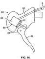
- a first end of a hydraulic brake line 8 is connected to a handlebar mounted actuator 80 (see FIG. 16 ), and a second end of hydraulic brake line 8 is connected to brake assembly 50 in a manner that is well known in the art and is described as follows.
- Barbed fitting 30 has a barbed cylindrical portion that is received in the second end of hydraulic brake line 8.
- One end of a compression ring 29 abuts a tapered section of a bore in second brake arm 3.
- the top portion of the tapered bore is threaded, and threadably receives a compression nut 31.
- Hydraulic brake line 8, along with barbed fitting 30, is also received in the bore in second brake arm 3.
- Compression nut 31 is tightened to a specified torque, deforming compression ring 29 such that compression ring 29, hydraulic brake line 8, and barbed fitting 30 form a leak-proof seal.
- the connection of the hydraulic line can include any suitable connection.
- a piston 24 is received in a piston bore or cylinder 24a formed in second brake arm 3.
- Piston 24 has a circumferential groove in which is located a seal, which may be in the form of an O-ring 26 and a back-up ring 25.
- a first end of piston 24 preferably has a tapered bore with a spherically shaped bottom against which is abutted a corresponding spherically shaped end of adjust bolt 22.
- cross-drilled hole 3a of second brake arm 3 runs transversely across the bore that receives piston 24 and the bore that receives hydraulic brake line 8.
- Connecting holes 34, 35 connect cross-drilled hole 3a to the cylinder 24a that receives piston 24 and the bore that receives hydraulic brake line 8.
- hydraulic brake line 8 and the bore 24a that receives piston 24 are in fluid communication with each other.
- An open end of cross-drilled hole 3a is threaded and receives a small O-ring 28.
- a bleed screw 27 is threadably received in the open end of cross-drilled hole 3a, and is tightened against O-ring 28 to form a leak-proof seal.
- the piston 24 and cylinder 24a may be disposed separate from the brake arms 2, 3 but configured to operate therebetween.
- FIGS. 4 and 11 show brake assembly 50 in its unactuated state.
- return spring 11 urges first brake arm 2 in a counter-clockwise direction around pivot bolt 1
- return spring 11 urges second brake arm 3 in a clockwise direction around pivot bolt 1.
- counter-clockwise rotation of first brake arm 2 and clockwise rotation of second brake arm 3 are prevented by the abutment of the bottom of piston 24 with the bottom of the bore 24a in second brake arm 3 that receives piston 24.
- first brake arm 2 and second brake arm 3 are sprung against each other by spring 11.
- the parts of the arms 2, 3 that hold respective brake pad assemblies are biased into an open or apart condition.
- hydraulic brake line 8, cross-drilled hole 3a, connecting holes 34, 35 and the handlebar-mounted actuator 80 are filled with one continuous volume of any suitable hydraulic fluid.
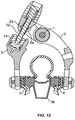
- the handlebar-mounted actuator 80 is actuated by manipulating lever 82, advancing piston 84 within master cylinder 86 displaces a volume of fluid from reservoir 88 through fluid passageway 90 to flow through hydraulic brake line 8, through cross-drilled hole 3a, and upwards into the bore 24a that receives piston 24, pushing piston 24 upwards as shown in FIG. 12 .
- the piston 84 preferably has seals 92. This upwards force on piston 24 causes first brake arm 2 to rotate clockwise (in FIG.
- first brake arm 2 and second brake arm 3 continue to rotate about pivot bolt 1 until brake pad assemblies 4, 5 contact side walls of a bicycle rim 36, providing a braking force to slow rotational motion of bicycle rim 36. Further clockwise movement of first brake arm 2 and counter-clockwise movement of second brake arm 3 is prevented by the presence of bicycle rim 36.
- first brake arm 2 rotates counter-clockwise and second brake arm 3 rotates clockwise due to the urging force of return spring 11, and piston 24 pushes hydraulic fluid out of the bore 24a that receives piston 24 and back towards the handlebar-mounted actuator, until brake assembly 50 is again positioned in the unactuated state shown in FIG. 11 .
- first brake pad assembly 4 and second brake pad assembly 5 are separated by a distance D1.
- adjust knob 7 which forms part of and actuates an adjust mechanism 96 (see also FIG.
- adjust knob 7 is simply rotated in a second direction opposite the first direction, causing adjust bolt 22 to move axially in the opposite direction, in turn causing first brake arm 2 to rotate clockwise (in FIG. 13 ) and causing second brake arm 3 to rotate counter-clockwise against the urging force of return spring 11 until brake pad assemblies 4, 5 are separated by the desired third distance D3 that is less than D1.
- Another feature of a preferred embodiment of the invention is the ability to quickly move brake pad assemblies 4, 5 apart to facilitate wheel removal.
- This feature is known as "quick-release", and is described as follows, referring to parts of the brake assembly 50 that form the quick-release mechanism 94.
- detent block 33 is omitted so that other structure can be seen more clearly.
- brake assembly 50 is shown in the same non-actuated state as shown in FIG. 11 , with quick-release lever 6 in the closed position.
- bore 6b of quick-release lever 6 and adjust bolt receiver 23 are oriented towards piston 24.
- quick-release lever 6 is simply rotated back to the closed position shown in FIG. 1 , which re-orients bore 6b and adjust bolt receiver 23 towards piston 24 as shown in FIG. 14 , causing adjust bolt 22 to move relative to first brake arm 2 as shown in FIG. 14 , forcing first brake arm 2 to rotate clockwise (in FIG. 14 ) against the urging force of return spring 11, and forcing second brake arm 3 to rotate counter-clockwise (in FIG. 14 ) against the urging force of return spring 11, until brake pad assemblies 4, 5 are once again separated by a distance D1.
- FIG. 11a shows a hydraulic brake assembly according to another embodiment of the invention.
- a first brake arm 202 and brake pad assembly 4 is pivotally connected to a bicycle at pivot element 1.
- a second brake arm 203 and brake pad assembly 5 is configured to pivot relative to the first brake arm.
- a piston 224 is received in a piston bore or cylinder 224a formed in second brake arm 203.
- Piston 224 has a circumferential groove in which is located a seal, which may be in the form of an O-ring 226 and a back-up ring 225.
- Piston 224 has a bearing end 224b that extends from the cylinder 224a of the second arm 203 in the direction of the upper end 200a of the first arm 202.
- the first arm 202 includes, at or near the upper end 200a, a surface 222, preferably in the form of a curved surface that is shaped and positioned to contact the bearing end 224b of piston 224.
- fluid entering cylinder 224a displaces piston 224 in brake arm 203 in the direction of the upper end 200a of first arm 202.
- the piston bearing end 224b pushes against surface 222, and thus the upper end 200a, in order to cause the arms 202, 203 to pivot.
- the pivoting of arms 202, 204 cause the brake pad assemblies 4, 5 to be drawn towards each other when piston 224 is displaced outwardly from cylinder 224a.
- FIGS. 18-21 shows yet another embodiment of the invention, wherein most of the components are the same as or are similar to those shown in FIGS. 1-17 and described herein.
- the brake assembly 150 includes first brake arm 102 and second brake arm 103, both may be pivotally connected to a frame member. Most of the components of a quick-release mechanism 194 and the adjust mechanism 196 are generally positioned at or within a fork arrangement 198 of an upper end 200 of arm 102.
- Adjust mechanism 196 includes an adjust lever 107 that extends from the adjust mechanism on arm 102. Operation of the adjust lever 107 causes the movement of the link member 122.
- Quick-release mechanism 194 includes a quick-release lever 106 that extends from the quick-release mechanism on arm 102. Operation of the quick-release lever 106 also causes movement of the link member 122.
- Both quick-release mechanism 194 and adjust mechanism 196 act on link member 122, which acts on piston 124 disposed in arm 103.
- the hydraulic brake line 8 ( FIG. 18 ) is connected to arm 103 via fitting 31 in the same fashion as in the previous embodiment.
- FIG. 19 shows the opening 204 in the arm 103, into which the fitting 31 is fitted into the arm and through which hydraulic fluid passes to and from the cylinder 24a formed in the arm.
- Adjust knob 107 has internal threads 107a that threadably connect the adjust knob to the link member 122.
- a spring 32 biases the knob 107 and the head 22a apart.
- Both the adjust knob 107 and the link member 122 pass through receiver 123, although receiver has a smooth walled interior 123a. For adjustment of the adjustment mechanism 196 to occur, when the knob 107 is turned, the link member 122 should be prevented from turning.
- the arrangement includes a piston 124 in cylinder 124a that is prevented by turning, for example, by providing the piston and seal 126 in a non-cylindrical shape, for example an oval shape, which is reciprocally disposed in a matching cylinder 124a (for example a corresponding oval shape).
- the piston 124 also has a socket 124b that is non-round and an end profile 122a on the link member 122 that non-rotatably fits within the socket.
- the piston 124 constrains the link member 122 from turning by virtue of the non-round configuration of the piston and cylinder 124a in combination with the locking socket 124b and end profile 122a.
Landscapes
- Engineering & Computer Science (AREA)
- Mechanical Engineering (AREA)
- General Engineering & Computer Science (AREA)
- Transportation (AREA)
- Transmission Of Braking Force In Braking Systems (AREA)
- Braking Arrangements (AREA)
Claims (4)
- Ensemble de frein hydraulique (50) pour une bicyclette, la bicyclette comprenant un maître-cylindre (86) actionné par un levier de frein (82), l'ensemble de frein hydraulique (50) comprenant :un premier bras de frein (2) ;un deuxième bras de frein (3), dans lequel les premiers et deuxième bras de frein sont connectés de manière pivotante à un élément de cadre de la bicyclette sur un pivot commun ;un cylindre (24a) étant adapté pour être en communication fluidique avec le maître-cylindre (86) ;un piston (24) disposé de manière coulissante dans le cylindre (24a) et configuré d'une manière telle que le déplacement du piston (24) en réponse à un déplacement fluidique dans l'ensemble de frein hydraulique (50) amène le premier bras de frein (2) et le deuxième bras de frein (3) à pivoter, caractérisé en ce que le cylindre (24a) est formé dans l'un parmi les premier et deuxième bras de frein (2, 3).
- Ensemble de frein hydraulique (50) selon la revendication 1, comprenant en outre un mécanisme à libération rapide (94) et un mécanisme de réglage (196) configurés sur l'autre parmi les premier et deuxième bras de frein (2, 3) pour agir entre les premier et deuxième bras de frein (2, 3) pour régler l'espace entre eux, dans lequel en particulier l'autre parmi les premier et deuxième bras de frein (2, 3) comprend une extrémité supérieure sur un système de fourche et dans lequel le mécanisme de réglage (196) et le mécanisme à libération rapide (94) sont disposés au niveau du système de fourche.
- Ensemble de frein hydraulique (50) selon la revendication 2, comprenant en outre un élément de liaison (122) qui s'étend entre les premier et deuxième bras de frein (2, 3) et dans lequel le mécanisme à libération rapide (94) et le mécanisme de réglage (196) partagent l'élément de liaison (122), dans lequel en particulier le mécanisme à libération rapide (94) et le mécanisme de réglage (196) agissent sur l'élément de liaison (122) pour régler l'espace entre les premier et deuxième bras de frein (2, 3).
- Ensemble de frein hydraulique (50) selon la revendication 3, dans lequel l'élément de liaison (122) contacte le piston et agit sur le piston pour régler l'espace entre les premier et deuxième bras de frein (2, 3).
Applications Claiming Priority (2)
| Application Number | Priority Date | Filing Date | Title |
|---|---|---|---|
| US13/291,797 US9663184B2 (en) | 2011-11-08 | 2011-11-08 | Hydraulic rim brake |
| EP12007592.4A EP2591959B1 (fr) | 2011-11-08 | 2012-11-08 | Frein hydraulique sur jante |
Related Parent Applications (2)
| Application Number | Title | Priority Date | Filing Date |
|---|---|---|---|
| EP12007592.4A Division-Into EP2591959B1 (fr) | 2011-11-08 | 2012-11-08 | Frein hydraulique sur jante |
| EP12007592.4A Division EP2591959B1 (fr) | 2011-11-08 | 2012-11-08 | Frein hydraulique sur jante |
Publications (2)
| Publication Number | Publication Date |
|---|---|
| EP2905211A1 EP2905211A1 (fr) | 2015-08-12 |
| EP2905211B1 true EP2905211B1 (fr) | 2018-09-19 |
Family
ID=47225893
Family Applications (2)
| Application Number | Title | Priority Date | Filing Date |
|---|---|---|---|
| EP12007592.4A Not-in-force EP2591959B1 (fr) | 2011-11-08 | 2012-11-08 | Frein hydraulique sur jante |
| EP15000831.6A Not-in-force EP2905211B1 (fr) | 2011-11-08 | 2012-11-08 | Frein hydraulique sur jante |
Family Applications Before (1)
| Application Number | Title | Priority Date | Filing Date |
|---|---|---|---|
| EP12007592.4A Not-in-force EP2591959B1 (fr) | 2011-11-08 | 2012-11-08 | Frein hydraulique sur jante |
Country Status (5)
| Country | Link |
|---|---|
| US (1) | US9663184B2 (fr) |
| EP (2) | EP2591959B1 (fr) |
| CN (1) | CN103085927B (fr) |
| DE (1) | DE102012021826A1 (fr) |
| TW (1) | TWI520873B (fr) |
Families Citing this family (11)
| Publication number | Priority date | Publication date | Assignee | Title |
|---|---|---|---|---|
| US8869949B2 (en) | 2012-06-26 | 2014-10-28 | Sram, Llc | Rim brake |
| US9233731B1 (en) * | 2014-07-30 | 2016-01-12 | Shimano Inc. | Bicycle rim brake |
| CN105620639A (zh) * | 2014-11-03 | 2016-06-01 | 张瑞龙 | 脚踏车的油压煞车装置 |
| US9701362B2 (en) | 2015-02-27 | 2017-07-11 | Shimano Inc. | Bicycle brake device |
| US9764794B2 (en) * | 2015-02-27 | 2017-09-19 | Shimano Inc. | Bicycle brake device and bicycle rim brake device |
| US9415830B1 (en) | 2015-03-09 | 2016-08-16 | Shimano Inc. | Bicycle rim brake |
| US9908586B2 (en) | 2015-03-09 | 2018-03-06 | Shimano Inc. | Bicycle rim brake |
| CN105905221B (zh) * | 2016-06-03 | 2019-03-29 | 温芫鋐 | 自行车刹车器 |
| US11745549B2 (en) * | 2017-08-21 | 2023-09-05 | Sram. Llc | Pressure sensing assembly for a bicycle wheel |
| WO2022220826A1 (fr) * | 2021-04-14 | 2022-10-20 | Ox-Motorcycle Products, LLC | Système et dispositif de freinage hydraulique réglable pour motocyclette |
| US11325674B1 (en) * | 2021-05-25 | 2022-05-10 | Shimano Inc. | Operating device for human-powered vehicle |
Citations (1)
| Publication number | Priority date | Publication date | Assignee | Title |
|---|---|---|---|---|
| EP0601591A1 (fr) * | 1992-12-10 | 1994-06-15 | FICHTEL & SACHS AG | Dispositif de commande hydraulique pour freins et dérailleurs des bicyclettes ou des véhicules similaires |
Family Cites Families (18)
| Publication number | Priority date | Publication date | Assignee | Title |
|---|---|---|---|---|
| FR868090A (fr) | 1940-12-13 | 1941-12-15 | Freins à patins ou à tambour à commande hydraulique avec pompe de commande par rétropédalage | |
| BE537716A (fr) | 1953-02-25 | |||
| US3338337A (en) | 1965-12-15 | 1967-08-29 | Elmer E Freeland | Hydraulic cycle brake |
| US3554334A (en) * | 1968-06-17 | 1971-01-12 | Keizo Shimano | Hydraulic bicycle brake system |
| US3776333A (en) * | 1971-09-09 | 1973-12-04 | W Mathauser | Bicycle brake arrangement |
| US3899057A (en) * | 1972-01-25 | 1975-08-12 | Dba Sa | Hydraulic control circuit |
| US3899056A (en) * | 1973-04-30 | 1975-08-12 | Carl L Doerr | Hydraulic bicycle brake assembly |
| US4391353A (en) * | 1981-01-23 | 1983-07-05 | Mathauser William R | Hand operated hydraulic bicycle brake |
| US4632225A (en) * | 1985-05-08 | 1986-12-30 | Mathauser William R | Brake device for bicycles |
| US5813501A (en) * | 1996-10-18 | 1998-09-29 | Terry, Sr.; Maurice C. | Hand operated hydraulic vehicle brake |
| US6334513B1 (en) * | 2000-01-27 | 2002-01-01 | Yih Cherng Co., Ltd. | Disc brake assembly for a bicycle |
| US7975810B2 (en) * | 2007-08-10 | 2011-07-12 | Liu Robert Z | Cam activated bicycle wheel brake |
| US8061487B2 (en) * | 2009-03-23 | 2011-11-22 | Szu-Fang Tsai | Mechanism for quickly loosening and tightening brake cable in caliper brake of bicycle |
| US8678144B2 (en) * | 2009-07-17 | 2014-03-25 | Shimano, Inc. | Hydraulic caliper brake for a bicycle |
| US8459416B2 (en) * | 2009-07-17 | 2013-06-11 | Shimano, Inc. | Quick-release apparatus for a bicycle hydraulic caliper brake |
| JP2011143764A (ja) | 2010-01-12 | 2011-07-28 | Tokyo R & D Co Ltd | 自転車用ブレーキ及び自転車 |
| US8720651B2 (en) * | 2010-05-27 | 2014-05-13 | Shimano, Inc. | Reversible hydraulic caliper brake for a bicycle |
| EP3000708B1 (fr) * | 2011-03-04 | 2020-06-17 | Shimano Inc. | Ensemble de frein de bicyclette |
-
2011
- 2011-11-08 US US13/291,797 patent/US9663184B2/en not_active Expired - Fee Related
-
2012
- 2012-10-26 TW TW101139739A patent/TWI520873B/zh active
- 2012-11-08 EP EP12007592.4A patent/EP2591959B1/fr not_active Not-in-force
- 2012-11-08 DE DE102012021826A patent/DE102012021826A1/de active Pending
- 2012-11-08 CN CN201210443864.1A patent/CN103085927B/zh active Active
- 2012-11-08 EP EP15000831.6A patent/EP2905211B1/fr not_active Not-in-force
Patent Citations (1)
| Publication number | Priority date | Publication date | Assignee | Title |
|---|---|---|---|---|
| EP0601591A1 (fr) * | 1992-12-10 | 1994-06-15 | FICHTEL & SACHS AG | Dispositif de commande hydraulique pour freins et dérailleurs des bicyclettes ou des véhicules similaires |
Also Published As
| Publication number | Publication date |
|---|---|
| CN103085927B (zh) | 2015-12-02 |
| EP2591959A3 (fr) | 2014-02-05 |
| TW201325983A (zh) | 2013-07-01 |
| EP2591959B1 (fr) | 2015-06-24 |
| TWI520873B (zh) | 2016-02-11 |
| US9663184B2 (en) | 2017-05-30 |
| EP2591959A2 (fr) | 2013-05-15 |
| DE102012021826A1 (de) | 2013-05-08 |
| US20130112510A1 (en) | 2013-05-09 |
| CN103085927A (zh) | 2013-05-08 |
| EP2905211A1 (fr) | 2015-08-12 |
Similar Documents
| Publication | Publication Date | Title |
|---|---|---|
| US9663184B2 (en) | Hydraulic rim brake | |
| EP2275335B1 (fr) | Frein hydraulique à mâchoires pour bicyclette | |
| US9840304B2 (en) | Hydraulic brake actuation device | |
| CN103359246B (zh) | 自行车液压部件操作设备 | |
| US7942250B2 (en) | Bicycle hydraulic brake device | |
| US8201670B2 (en) | Bicycle hydraulic brake actuation device | |
| EP2275334B1 (fr) | Appareil de libération rapide pour frein hydraulique à mâchoires de bicyclette | |
| US6394236B1 (en) | Cable disc brake | |
| US9096288B2 (en) | Dual hydraulic controller for bicycle components | |
| US6557671B1 (en) | Cable disc brake | |
| US20110290595A1 (en) | Reversible hydraulic caliper brake for a bicycle | |
| US8651244B2 (en) | Hydraulic brake device | |
| EP1325863B1 (fr) | Maítre cylindre pour frein à disque ayant une ajustabilité à la volée | |
| US10710672B2 (en) | Bicycle rim brake | |
| US8336680B2 (en) | Center-pull bicycle brake with synchronized brake arms | |
| US8336308B2 (en) | Lever device for operating a hydraulic actuator, particularly for motorcycles | |
| US20120124991A1 (en) | Method and apparatus for lever stroke adjustment | |
| EP1595782B1 (fr) | Maître cylindre pour frein à disque ayant une ajustabilité à la volée | |
| US10384741B2 (en) | Bicycle hydraulic operating device | |
| US20160264212A1 (en) | Bicycle rim brake | |
| US10155562B2 (en) | Hydraulic braking device |
Legal Events
| Date | Code | Title | Description |
|---|---|---|---|
| PUAI | Public reference made under article 153(3) epc to a published international application that has entered the european phase |
Free format text: ORIGINAL CODE: 0009012 |
|
| AC | Divisional application: reference to earlier application |
Ref document number: 2591959 Country of ref document: EP Kind code of ref document: P |
|
| AK | Designated contracting states |
Kind code of ref document: A1 Designated state(s): AL AT BE BG CH CY CZ DE DK EE ES FI FR GB GR HR HU IE IS IT LI LT LU LV MC MK MT NL NO PL PT RO RS SE SI SK SM TR |
|
| 17P | Request for examination filed |
Effective date: 20160204 |
|
| RBV | Designated contracting states (corrected) |
Designated state(s): AL AT BE BG CH CY CZ DE DK EE ES FI FR GB GR HR HU IE IS IT LI LT LU LV MC MK MT NL NO PL PT RO RS SE SI SK SM TR |
|
| STAA | Information on the status of an ep patent application or granted ep patent |
Free format text: STATUS: EXAMINATION IS IN PROGRESS |
|
| 17Q | First examination report despatched |
Effective date: 20171019 |
|
| GRAP | Despatch of communication of intention to grant a patent |
Free format text: ORIGINAL CODE: EPIDOSNIGR1 |
|
| STAA | Information on the status of an ep patent application or granted ep patent |
Free format text: STATUS: GRANT OF PATENT IS INTENDED |
|
| INTG | Intention to grant announced |
Effective date: 20180404 |
|
| GRAS | Grant fee paid |
Free format text: ORIGINAL CODE: EPIDOSNIGR3 |
|
| GRAA | (expected) grant |
Free format text: ORIGINAL CODE: 0009210 |
|
| STAA | Information on the status of an ep patent application or granted ep patent |
Free format text: STATUS: THE PATENT HAS BEEN GRANTED |
|
| AC | Divisional application: reference to earlier application |
Ref document number: 2591959 Country of ref document: EP Kind code of ref document: P |
|
| AK | Designated contracting states |
Kind code of ref document: B1 Designated state(s): AL AT BE BG CH CY CZ DE DK EE ES FI FR GB GR HR HU IE IS IT LI LT LU LV MC MK MT NL NO PL PT RO RS SE SI SK SM TR |
|
| REG | Reference to a national code |
Ref country code: GB Ref legal event code: FG4D |
|
| REG | Reference to a national code |
Ref country code: CH Ref legal event code: EP |
|
| REG | Reference to a national code |
Ref country code: AT Ref legal event code: REF Ref document number: 1042938 Country of ref document: AT Kind code of ref document: T Effective date: 20181015 |
|
| REG | Reference to a national code |
Ref country code: IE Ref legal event code: FG4D Ref country code: FR Ref legal event code: PLFP Year of fee payment: 7 |
|
| REG | Reference to a national code |
Ref country code: DE Ref legal event code: R096 Ref document number: 602012051424 Country of ref document: DE |
|
| REG | Reference to a national code |
Ref country code: NL Ref legal event code: FP |
|
| PGFP | Annual fee paid to national office [announced via postgrant information from national office to epo] |
Ref country code: NL Payment date: 20181030 Year of fee payment: 7 |
|
| PG25 | Lapsed in a contracting state [announced via postgrant information from national office to epo] |
Ref country code: LT Free format text: LAPSE BECAUSE OF FAILURE TO SUBMIT A TRANSLATION OF THE DESCRIPTION OR TO PAY THE FEE WITHIN THE PRESCRIBED TIME-LIMIT Effective date: 20180919 Ref country code: RS Free format text: LAPSE BECAUSE OF FAILURE TO SUBMIT A TRANSLATION OF THE DESCRIPTION OR TO PAY THE FEE WITHIN THE PRESCRIBED TIME-LIMIT Effective date: 20180919 Ref country code: BG Free format text: LAPSE BECAUSE OF FAILURE TO SUBMIT A TRANSLATION OF THE DESCRIPTION OR TO PAY THE FEE WITHIN THE PRESCRIBED TIME-LIMIT Effective date: 20181219 Ref country code: SE Free format text: LAPSE BECAUSE OF FAILURE TO SUBMIT A TRANSLATION OF THE DESCRIPTION OR TO PAY THE FEE WITHIN THE PRESCRIBED TIME-LIMIT Effective date: 20180919 Ref country code: GR Free format text: LAPSE BECAUSE OF FAILURE TO SUBMIT A TRANSLATION OF THE DESCRIPTION OR TO PAY THE FEE WITHIN THE PRESCRIBED TIME-LIMIT Effective date: 20181220 Ref country code: NO Free format text: LAPSE BECAUSE OF FAILURE TO SUBMIT A TRANSLATION OF THE DESCRIPTION OR TO PAY THE FEE WITHIN THE PRESCRIBED TIME-LIMIT Effective date: 20181219 Ref country code: FI Free format text: LAPSE BECAUSE OF FAILURE TO SUBMIT A TRANSLATION OF THE DESCRIPTION OR TO PAY THE FEE WITHIN THE PRESCRIBED TIME-LIMIT Effective date: 20180919 |
|
| REG | Reference to a national code |
Ref country code: LT Ref legal event code: MG4D |
|
| PG25 | Lapsed in a contracting state [announced via postgrant information from national office to epo] |
Ref country code: HR Free format text: LAPSE BECAUSE OF FAILURE TO SUBMIT A TRANSLATION OF THE DESCRIPTION OR TO PAY THE FEE WITHIN THE PRESCRIBED TIME-LIMIT Effective date: 20180919 Ref country code: LV Free format text: LAPSE BECAUSE OF FAILURE TO SUBMIT A TRANSLATION OF THE DESCRIPTION OR TO PAY THE FEE WITHIN THE PRESCRIBED TIME-LIMIT Effective date: 20180919 Ref country code: AL Free format text: LAPSE BECAUSE OF FAILURE TO SUBMIT A TRANSLATION OF THE DESCRIPTION OR TO PAY THE FEE WITHIN THE PRESCRIBED TIME-LIMIT Effective date: 20180919 |
|
| PGFP | Annual fee paid to national office [announced via postgrant information from national office to epo] |
Ref country code: FR Payment date: 20181017 Year of fee payment: 7 |
|
| REG | Reference to a national code |
Ref country code: AT Ref legal event code: MK05 Ref document number: 1042938 Country of ref document: AT Kind code of ref document: T Effective date: 20180919 |
|
| PG25 | Lapsed in a contracting state [announced via postgrant information from national office to epo] |
Ref country code: RO Free format text: LAPSE BECAUSE OF FAILURE TO SUBMIT A TRANSLATION OF THE DESCRIPTION OR TO PAY THE FEE WITHIN THE PRESCRIBED TIME-LIMIT Effective date: 20180919 Ref country code: IT Free format text: LAPSE BECAUSE OF FAILURE TO SUBMIT A TRANSLATION OF THE DESCRIPTION OR TO PAY THE FEE WITHIN THE PRESCRIBED TIME-LIMIT Effective date: 20180919 Ref country code: CZ Free format text: LAPSE BECAUSE OF FAILURE TO SUBMIT A TRANSLATION OF THE DESCRIPTION OR TO PAY THE FEE WITHIN THE PRESCRIBED TIME-LIMIT Effective date: 20180919 Ref country code: EE Free format text: LAPSE BECAUSE OF FAILURE TO SUBMIT A TRANSLATION OF THE DESCRIPTION OR TO PAY THE FEE WITHIN THE PRESCRIBED TIME-LIMIT Effective date: 20180919 Ref country code: AT Free format text: LAPSE BECAUSE OF FAILURE TO SUBMIT A TRANSLATION OF THE DESCRIPTION OR TO PAY THE FEE WITHIN THE PRESCRIBED TIME-LIMIT Effective date: 20180919 Ref country code: IS Free format text: LAPSE BECAUSE OF FAILURE TO SUBMIT A TRANSLATION OF THE DESCRIPTION OR TO PAY THE FEE WITHIN THE PRESCRIBED TIME-LIMIT Effective date: 20190119 Ref country code: ES Free format text: LAPSE BECAUSE OF FAILURE TO SUBMIT A TRANSLATION OF THE DESCRIPTION OR TO PAY THE FEE WITHIN THE PRESCRIBED TIME-LIMIT Effective date: 20180919 Ref country code: PL Free format text: LAPSE BECAUSE OF FAILURE TO SUBMIT A TRANSLATION OF THE DESCRIPTION OR TO PAY THE FEE WITHIN THE PRESCRIBED TIME-LIMIT Effective date: 20180919 |
|
| PG25 | Lapsed in a contracting state [announced via postgrant information from national office to epo] |
Ref country code: SK Free format text: LAPSE BECAUSE OF FAILURE TO SUBMIT A TRANSLATION OF THE DESCRIPTION OR TO PAY THE FEE WITHIN THE PRESCRIBED TIME-LIMIT Effective date: 20180919 Ref country code: PT Free format text: LAPSE BECAUSE OF FAILURE TO SUBMIT A TRANSLATION OF THE DESCRIPTION OR TO PAY THE FEE WITHIN THE PRESCRIBED TIME-LIMIT Effective date: 20190119 Ref country code: SM Free format text: LAPSE BECAUSE OF FAILURE TO SUBMIT A TRANSLATION OF THE DESCRIPTION OR TO PAY THE FEE WITHIN THE PRESCRIBED TIME-LIMIT Effective date: 20180919 |
|
| REG | Reference to a national code |
Ref country code: DE Ref legal event code: R097 Ref document number: 602012051424 Country of ref document: DE |
|
| REG | Reference to a national code |
Ref country code: CH Ref legal event code: PL |
|
| PLBE | No opposition filed within time limit |
Free format text: ORIGINAL CODE: 0009261 |
|
| STAA | Information on the status of an ep patent application or granted ep patent |
Free format text: STATUS: NO OPPOSITION FILED WITHIN TIME LIMIT |
|
| PG25 | Lapsed in a contracting state [announced via postgrant information from national office to epo] |
Ref country code: MC Free format text: LAPSE BECAUSE OF FAILURE TO SUBMIT A TRANSLATION OF THE DESCRIPTION OR TO PAY THE FEE WITHIN THE PRESCRIBED TIME-LIMIT Effective date: 20180919 Ref country code: DK Free format text: LAPSE BECAUSE OF FAILURE TO SUBMIT A TRANSLATION OF THE DESCRIPTION OR TO PAY THE FEE WITHIN THE PRESCRIBED TIME-LIMIT Effective date: 20180919 Ref country code: LU Free format text: LAPSE BECAUSE OF NON-PAYMENT OF DUE FEES Effective date: 20181108 |
|
| REG | Reference to a national code |
Ref country code: BE Ref legal event code: MM Effective date: 20181130 |
|
| REG | Reference to a national code |
Ref country code: IE Ref legal event code: MM4A |
|
| 26N | No opposition filed |
Effective date: 20190620 |
|
| GBPC | Gb: european patent ceased through non-payment of renewal fee |
Effective date: 20181219 |
|
| PG25 | Lapsed in a contracting state [announced via postgrant information from national office to epo] |
Ref country code: LI Free format text: LAPSE BECAUSE OF NON-PAYMENT OF DUE FEES Effective date: 20181130 Ref country code: CH Free format text: LAPSE BECAUSE OF NON-PAYMENT OF DUE FEES Effective date: 20181130 |
|
| PG25 | Lapsed in a contracting state [announced via postgrant information from national office to epo] |
Ref country code: IE Free format text: LAPSE BECAUSE OF NON-PAYMENT OF DUE FEES Effective date: 20181108 Ref country code: SI Free format text: LAPSE BECAUSE OF FAILURE TO SUBMIT A TRANSLATION OF THE DESCRIPTION OR TO PAY THE FEE WITHIN THE PRESCRIBED TIME-LIMIT Effective date: 20180919 |
|
| PG25 | Lapsed in a contracting state [announced via postgrant information from national office to epo] |
Ref country code: BE Free format text: LAPSE BECAUSE OF NON-PAYMENT OF DUE FEES Effective date: 20181130 |
|
| PG25 | Lapsed in a contracting state [announced via postgrant information from national office to epo] |
Ref country code: GB Free format text: LAPSE BECAUSE OF NON-PAYMENT OF DUE FEES Effective date: 20181219 |
|
| PG25 | Lapsed in a contracting state [announced via postgrant information from national office to epo] |
Ref country code: MT Free format text: LAPSE BECAUSE OF NON-PAYMENT OF DUE FEES Effective date: 20181108 |
|
| PG25 | Lapsed in a contracting state [announced via postgrant information from national office to epo] |
Ref country code: TR Free format text: LAPSE BECAUSE OF FAILURE TO SUBMIT A TRANSLATION OF THE DESCRIPTION OR TO PAY THE FEE WITHIN THE PRESCRIBED TIME-LIMIT Effective date: 20180919 |
|
| PG25 | Lapsed in a contracting state [announced via postgrant information from national office to epo] |
Ref country code: HU Free format text: LAPSE BECAUSE OF FAILURE TO SUBMIT A TRANSLATION OF THE DESCRIPTION OR TO PAY THE FEE WITHIN THE PRESCRIBED TIME-LIMIT; INVALID AB INITIO Effective date: 20121108 Ref country code: CY Free format text: LAPSE BECAUSE OF FAILURE TO SUBMIT A TRANSLATION OF THE DESCRIPTION OR TO PAY THE FEE WITHIN THE PRESCRIBED TIME-LIMIT Effective date: 20180919 Ref country code: MK Free format text: LAPSE BECAUSE OF NON-PAYMENT OF DUE FEES Effective date: 20180919 |
|
| REG | Reference to a national code |
Ref country code: NL Ref legal event code: MM Effective date: 20191201 |
|
| PG25 | Lapsed in a contracting state [announced via postgrant information from national office to epo] |
Ref country code: NL Free format text: LAPSE BECAUSE OF NON-PAYMENT OF DUE FEES Effective date: 20191201 |
|
| PG25 | Lapsed in a contracting state [announced via postgrant information from national office to epo] |
Ref country code: FR Free format text: LAPSE BECAUSE OF NON-PAYMENT OF DUE FEES Effective date: 20191130 |
|
| REG | Reference to a national code |
Ref country code: DE Ref legal event code: R082 Ref document number: 602012051424 Country of ref document: DE Representative=s name: THUM, MOETSCH, WEICKERT PATENTANWAELTE PARTG M, DE Ref country code: DE Ref legal event code: R082 Ref document number: 602012051424 Country of ref document: DE Representative=s name: THUM & PARTNER THUM MOETSCH WEICKERT PATENTANW, DE |
|
| PGFP | Annual fee paid to national office [announced via postgrant information from national office to epo] |
Ref country code: DE Payment date: 20221012 Year of fee payment: 11 |
|
| P01 | Opt-out of the competence of the unified patent court (upc) registered |
Effective date: 20230524 |
|
| REG | Reference to a national code |
Ref country code: DE Ref legal event code: R119 Ref document number: 602012051424 Country of ref document: DE |
|
| PG25 | Lapsed in a contracting state [announced via postgrant information from national office to epo] |
Ref country code: DE Free format text: LAPSE BECAUSE OF NON-PAYMENT OF DUE FEES Effective date: 20240601 |
|
| PG25 | Lapsed in a contracting state [announced via postgrant information from national office to epo] |
Ref country code: DE Free format text: LAPSE BECAUSE OF NON-PAYMENT OF DUE FEES Effective date: 20240601 |