EP2905413A1 - Rollladenanlage und Methoden zum selektiven Öffnen und Schließen einer Klappe einer solchen Anlage - Google Patents
Rollladenanlage und Methoden zum selektiven Öffnen und Schließen einer Klappe einer solchen Anlage Download PDFInfo
- Publication number
- EP2905413A1 EP2905413A1 EP15154271.9A EP15154271A EP2905413A1 EP 2905413 A1 EP2905413 A1 EP 2905413A1 EP 15154271 A EP15154271 A EP 15154271A EP 2905413 A1 EP2905413 A1 EP 2905413A1
- Authority
- EP
- European Patent Office
- Prior art keywords
- valve
- rotation
- air
- installation
- winding shaft
- Prior art date
- Legal status (The legal status is an assumption and is not a legal conclusion. Google has not performed a legal analysis and makes no representation as to the accuracy of the status listed.)
- Withdrawn
Links
Images


Classifications
-
- E—FIXED CONSTRUCTIONS
- E06—DOORS, WINDOWS, SHUTTERS, OR ROLLER BLINDS IN GENERAL; LADDERS
- E06B—FIXED OR MOVABLE CLOSURES FOR OPENINGS IN BUILDINGS, VEHICLES, FENCES OR LIKE ENCLOSURES IN GENERAL, e.g. DOORS, WINDOWS, BLINDS, GATES
- E06B7/00—Special arrangements or measures in connection with doors or windows
- E06B7/02—Special arrangements or measures in connection with doors or windows for providing ventilation, e.g. through double windows; Arrangement of ventilation roses
-
- E—FIXED CONSTRUCTIONS
- E06—DOORS, WINDOWS, SHUTTERS, OR ROLLER BLINDS IN GENERAL; LADDERS
- E06B—FIXED OR MOVABLE CLOSURES FOR OPENINGS IN BUILDINGS, VEHICLES, FENCES OR LIKE ENCLOSURES IN GENERAL, e.g. DOORS, WINDOWS, BLINDS, GATES
- E06B9/00—Screening or protective devices for wall or similar openings, with or without operating or securing mechanisms; Closures of similar construction
- E06B9/02—Shutters, movable grilles, or other safety closing devices, e.g. against burglary
- E06B9/08—Roll-type closures
- E06B9/11—Roller shutters
- E06B9/17—Parts or details of roller shutters, e.g. suspension devices, shutter boxes, wicket doors, ventilation openings
- E06B9/17007—Shutter boxes; Details or component parts thereof
-
- E—FIXED CONSTRUCTIONS
- E06—DOORS, WINDOWS, SHUTTERS, OR ROLLER BLINDS IN GENERAL; LADDERS
- E06B—FIXED OR MOVABLE CLOSURES FOR OPENINGS IN BUILDINGS, VEHICLES, FENCES OR LIKE ENCLOSURES IN GENERAL, e.g. DOORS, WINDOWS, BLINDS, GATES
- E06B7/00—Special arrangements or measures in connection with doors or windows
- E06B7/02—Special arrangements or measures in connection with doors or windows for providing ventilation, e.g. through double windows; Arrangement of ventilation roses
- E06B7/10—Special arrangements or measures in connection with doors or windows for providing ventilation, e.g. through double windows; Arrangement of ventilation roses by special construction of the frame members
-
- E—FIXED CONSTRUCTIONS
- E06—DOORS, WINDOWS, SHUTTERS, OR ROLLER BLINDS IN GENERAL; LADDERS
- E06B—FIXED OR MOVABLE CLOSURES FOR OPENINGS IN BUILDINGS, VEHICLES, FENCES OR LIKE ENCLOSURES IN GENERAL, e.g. DOORS, WINDOWS, BLINDS, GATES
- E06B9/00—Screening or protective devices for wall or similar openings, with or without operating or securing mechanisms; Closures of similar construction
- E06B9/02—Shutters, movable grilles, or other safety closing devices, e.g. against burglary
- E06B9/08—Roll-type closures
- E06B9/11—Roller shutters
- E06B9/17—Parts or details of roller shutters, e.g. suspension devices, shutter boxes, wicket doors, ventilation openings
- E06B9/17007—Shutter boxes; Details or component parts thereof
- E06B9/17015—Shutter boxes; Details or component parts thereof made of at most two pieces; Front opening details
Definitions
- the invention relates to a rolling shutter installation, which allows to selectively close the opening of a building.
- the invention also relates to selective opening methods for an air change valve fitted to this installation.
- FR-A-2,773,584 a box for shutters, composed of two parts.
- a first part of the box is a U-shaped profile, with an open face facing the interior of the building in installed configuration of the box.
- a second part is a protective element closing the side face of the first part.
- This protective element comprises several rows of cells to avoid the formation of thermal and / or phonic bridges.
- This roller shutter installation does not include an air change valve.
- VMC controlled mechanical ventilation
- a single-flow controlled mechanical ventilation system clean air from outside is introduced into the home through windows or shutter boxes in the home.
- the management of the renewal of the air in the house can be managed manually by the inhabitant, by opening more or less the windows, or automatically by a hygro-sensitive mat, which controls the opening of a valve installed in the shutter box (s).
- This hygro-sensitive mat is housed in the outside air inlet and is able to absorb moisture. Thus, it regulates the opening of the valve or the boxes according to the moisture content absorbed, and indirectly, the humidity of the air inside the house.
- the renewal of air inside the house must be reduced to a minimum in winter to minimize heating consumption, it is called a hygienic air flow.
- a hygienic air flow when the indoor air is heavily polluted, for example with a carbon dioxide level, a sign of human presence, or too high humidity, it is advisable to increase the rate of air exchange by entering a volume. outside air more important.
- One solution is for example to install room sensors in the room to control the VMC and thus enter a volume of air adapted to the ambience of the room.
- a control unit of the VMC thus receives the information collected by the various sensors of the dwelling and regulates the opening of the air inlet valve or valves depending on the room environment. For a roller shutter, this requires to integrate into the casing of the shutter a mechanical device with electronic control valve opening, which is expensive and adds space inside the casing of the shutter.
- the invention more particularly intends to remedy by proposing a rolling shutter installation devoid of an additional mechanical device for controlling the air change valve.
- the invention relates to a rolling shutter installation, allowing the selective closure of an opening of a building, this installation comprising a receiving box of a winding shaft of the flap, and a renewal valve. air inside the building.
- the installation further comprises means of kinematic connection between the winding shaft and the valve and the selective opening of the valve is controlled by rotation of the winding shaft around its axis. axis.
- the selective opening of the valve is obtained simply by slightly rotating the winding shaft of the flap about its axis, which makes it possible to dispense with an additional mechanical device opening the valve .
- a single actuator is used to both move the shutter and open or close the valve.
- the control units for opening the flap and for moving the flap can be shared.
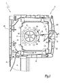
- This installation 1 comprises a housing 2, configured to be installed horizontally in the upper part of an opening of a building. More specifically, the casing 2 is installed above a frame 4 of the opening.
- the casing 2 is generally parallelepipedic and extends parallel to the ground in configuration installed in the opening of the building. It comprises a running part 24 and two end pieces, of which only one is visible at the figure 1 with the reference 22. The two end pieces 22 are arranged on both sides of the current portion 24.
- the box 2 also comprises a inspection door 20, which is formed by a side face of the box 2 facing the interior of the room. This inspection hatch 20 is removable or hinged to allow the fitter to access the interior of the casing 2 of the shutter during maintenance operations or for mounting the installation.
- a winding shaft 6 of the roller shutter is disposed inside the box 2 and extends along an axis X6, which is an axis of rotation of the shaft 6 and which is parallel to a longitudinal axis of the box 2.
- axis X6 is an axis of rotation of the shaft 6 and which is parallel to a longitudinal axis of the box 2.
- the shutter apron is not shown in the figures.
- the casing 2 comprises a slot O 1 for passage of the shutter and a guide tulip for the roller shutter within this slot O 1 .
- This tulip is not visible in the cutting planes of the Figures 1 to 6 .
- the casing 2 of the installation 1 is provided with a valve 12 for renewal of the air inside the room.
- This valve 12 is housed in an opening O 2 formed in the inspection door 20 of the box 2.
- the valve 12 can pivot about a horizontal axis X12 which is arranged on a lower edge of the opening O 2 and which is parallel to the X6 axis.
- the valve 12 is kinematically connected to the winding shaft 6. More specifically, the installation 1 comprises kinematic connection means between the valve 12 and the winding shaft 6. These means include a friction ring 8, which is fitted around the winding shaft 6 and a connecting rod 10 which connects the friction ring 8 to the valve 12.
- the rod 10 is rectilinear and articulated at its two ends, referenced 101 and 102.
- the connection between the rod 10 is the ring 8 is made by locking the end 101 of the rod 10 in a housing 80 of the ring 8 and the connection between the rod 10 and the valve 12 is formed by locking the end 102 in a spherical housing 120
- the ring 8 is thus a ring connecting the connecting rod 10 to the shaft 6 and, indirectly, the valve 12 to the shaft 6. It is immobile in translation along the winding shaft 6 and can slide around the shaft 6 or rotate integrally with it tion of the traction T1 exerted by the connecting rod 10 on the ring 8. This traction T1 opposes the rotational movement
- the valve 12 is shown in the open position at the figure 1 .
- the valve 12 delimits a passage P1 of the outside air, contained in the box 2, towards the interior of the building and vice versa.
- the flow of air flowing through the passage P1 is represented at figure 1 by a two-way arrow F2.
- a rotation R1 of the winding shaft 6 in the direction of unwinding of the flap integrally drives the rotation of the friction ring 8.
- the traction T1 exerted by the rod 10 on the ring 8 is low, that is to say that the valve 12 does not oppose the rotation of the ring 8 and rotates about the axis X12 to accompany the rotational movement of the ring 8.
- valve 12 This rotational movement tends to close the valve 12, as represented by the arrow F3, to reach the configuration of the figure 2 .
- the valve 12 closes in the direction of the interior of the box 2, that is to say that the arrow F3 is directed towards the shaft 6.
- the valve 12 When the valve 12 is completely closed, it It abuts against walls defining the opening O 2 and opposes the rotation of the ring 8 integrally with the winding shaft 6.
- the valve 12 exerts a force of retaining the rotation of the ring 8 and the traction T1 exerted by the connecting rod 6 on the ring 8 increases.
- a rotation R2 of the shaft 6 in the direction of the winding of the shutter implies, starting from the open position of the valve 12, the closure of the latter, to reach the configuration of the figure 3 .
- the ring 8 first rotates solidly with the shaft 6 and then rubs around the shaft 6 when the valve 12 is closed and when the rotation continues in the same direction the traction T1 exerted by the rod 10 then being sufficiently intense to immobilize the ring 8 in rotation.
- the traction T1 is, in practice, equal to the tension of the connecting rod 10 between its ends 101 and 102.
- the rotations R1 and R2 have an amplitude of the order of 110 ° on the Figures 1 to 3 .
- this amplitude is reduced, with the advantage of a minimal displacement of the apron during the adjustment phases of the opening / closing of the valve.
- Unrepresented room sensors are arranged in the dwelling, in particular in the most polluted parts of the dwelling such as the kitchen, the bathroom, the toilets or the bedrooms. These room sensors measure, among other things, the moisture content and / or the rate of carbon dioxide in the ambient air in these rooms and transmit this information to a unit not shown for controlling the valve 12.
- This control unit is an electronic unit housed directly in the control part of the shutter installation or in the ventilation management system to give a movement order to the roller shutter motor, which allows pooling the shutter and flap control units.
- the user actuates, for example by means of a remote control, the rise or fall of the roller shutter to reach a desired position, such as a fully closed position, fully open or halfway up.
- a desired position such as a fully closed position, fully open or halfway up.
- the control unit or control valve 12 analyzes the measurements made by the room sensors distributed within the dwelling and acts on the valve 12 accordingly, to open or close the air change valve 12. The renewal of the air in the home is therefore managed in a controlled manner.
- control unit of the valve 12 automatically sends a control signal, corresponding to a rotation of limited amplitude comparable to that of the rotations R1 and R2 to be made by the winding shaft 6 to open the valve 12.
- the valve 12 then works in all or nothing.
- This rotation of the winding shaft 6 is an additional rotation, which is performed automatically after the movement of the flap, and in the opposite direction of this movement. In other words, this additional rotation is performed in the opposite direction to the rotation performed to move or position the flap.
- the fact of performing the additional rotation in a direction opposite to the direction of movement of the flap makes it possible to avoid degrading the flap at the end of the stroke.
- the control unit When the roller shutter is actuated so that its apron is fully unwound, the additional rotation of limited amplitude of the winding shaft 6 to open the valve 12 is in the direction of the rise of the roller shutter not to degrade the blind.
- the control unit then implements the rotation R2 and the pieces 8 to 12 arrive in the configuration of the figure 3 .
- the additional rotation of limited opening amplitude of the valve 12 is the rotation R1 which is directed in the direction of the descent of the shutter.
- the displacement of the roller shutter generated by this additional rotation R1 is low, so that in fully wound position of the roller shutter inside the box 2, the flap is not caused to protrude out of the box 2 to the bottom, through the opening O 1 .
- the movement of the flap may be slightly exaggerated, relative to the target position, to compensate for the ascent or descent generated by the additional rotation R1 or R2 during the opening of the valve 12.
- the user does not generally require stop accuracy. It is therefore not necessary to anticipate this displacement.
- the room sensors record the quality of the air inside the house in real time.
- the valve 12 remains open until the interior air has been renewed enough.
- the valve 12 can be closed automatically by the control unit by means of an additional rotation R1 or R2, which in particular saves heating.
- the control unit adapts the degree of opening of the valve 12 according to the quality of the ambient air inside the house.
- the valve 12 then does not work all or nothing and can take a half-open position, in the case where a low air exchange is sufficient.
- the control unit of the valve 12 automatically sends a control signal, corresponding to an angle of rotation of the winding shaft 6 to be performed to achieve an opening degree of the desired valve 12.
- This angle of rotation depends on the atmosphere of the room, that is to say the degree of pollution. It is less than or equal to the amplitude of rotations R1 and R2.
- the variation of the degree of opening of the valve 12 makes it possible to adapt the width of the passage P1, and therefore the flow of air entering inside the dwelling.
- the closing or opening of the valve 12 is performed in a fractional manner.
- the closing of the valve 12 can be carried out in two or three motor pulses. There is talk of a progressive displacement of the valve 12.
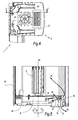
- FIG. 4 and 5 On the Figures 4 and 5 is shown a second embodiment of a rolling shutter installation 1.
- the valve 12 renewal air inside the building is disposed of an opening O 2 delimited in a tip 22 of the box 2.
- the tip 22 At the figure 4 , only a part of the tip 22 is shown to facilitate viewing of the interior of the box 2.
- valve 12 of air renewal is better visible at the figure 5 .
- the valve 12 can pivot about a vertical axis Z12 which is disposed on a lateral edge of the opening O 2 and which is perpendicular to the axis X6 of rotation of the shaft 6.
- the valve 12 is disposed behind a grid 11 on the side of the internal volume of the box 2 relative to the tip 22.
- the valve 12 is wide open during the phases of raising and lowering of the shutter.
- the valve 12 closes towards the outside of the box 2.
- the control or control unit of the valve 12 opens or closes the valve 12 according to the properties of the air inside the room. Indeed, in a similar manner to the first embodiment, room sensors are distributed within the dwelling and inform the control unit of the valve 12 of the humidity level and / or the carbon dioxide content of the indoor air. Based on these data, the control unit of the valve 12 can close the valve 12 if the ambient air has a satisfactory quality.
- the rotation shaft 6 performs an additional rotation in the direction of closing the valve 12.
- the valve 12 air exchange remains open, until the air inside the house is renewed enough.
- the valve 12 closes automatically through a rotation of the shaft 6 about the axis X6, under the control of the associated electronic control unit.
- the valve 12 also works in all or nothing. The option of a progressive displacement remains possible in the same way as in the first embodiment.
- the air change valve 12 is formed by the inspection flap 20.
- the inspection flap 20 is articulated on a lower face 26 of the casing 2, around an axis X12 parallel to the flap. X6 axis of rotation of the shaft 6.
- the inspection door 20 is linked to a friction ring 8 via a connecting rod 10 and the operation of the opening of the valve 12 is similar to that of the embodiment of the figure 1 , in particular according to the traction T1 exerted by the rod 10 on the ring 8.
- a rotation R3 of the winding shaft 6 in one direction or the other causes the closure F3 of the trapdoor visit 20, so that it remains closed during the rising and falling phases of the shutter apron and can be opened by performing an additional rotation, in the opposite direction, of the winding shaft 6, when the position of the shutter is frozen.
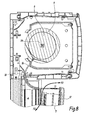
- FIG. 7 On the figure 7 is shown a fourth embodiment of a rolling shutter installation 1.
- the box 2 is raised relative to the frame 4, through a housing 14.
- the housing 14 is parallelepiped and has a length identical to that of the box 2.
- the housing 14 comprises a opening, of width less than or equal to the length of the housing 14. This opening is through so as to bring outside air inside the house.
- the opening of the housing 14 may be closed by a valve 12 and a strip of foam 15 for filtering the outside air is housed inside the opening.
- This strip of foam 15 makes it possible in particular to prevent the infiltration of dust or other particles inside the house and also plays the role of sound insulation to limit the transmission of outside noise.
- the valve 12 is articulated on the housing about an axis X12 parallel to the axis X6 of rotation of the shaft 6.
- the valve 12 is kinematically connected to the winding shaft 6 of the roller shutter. More specifically, the installation 1 comprises means of kinematic connection between the valve 12 and the winding shaft 6. These means include a friction ring 8, which is fitted around the winding shaft 6, a cable 16 of connection of the ring 8 to the valve 12 and a sheath 18 guiding the sliding of the cable 16. The sliding of the cable 16 in the sheath 18 causes the opening or closing of the valve 12.
- the selective opening of the valve 12 is managed identically to the first embodiment, that is to say that the ring 8 rotates integrally with the shaft 6 or rubs around the latter as a function of the traction T1 exerted by the cable 16, and indirectly by the valve 12, on the ring 8.
- a rotation R3 in one direction or the other of the shaft 6 causes the closure F3 of the valve 12.
- the valve 12 remains closed.
- an additional rotation of limited amplitude of the winding shaft 6 in one direction or the other can open the valve 12 to renew the air inside. of the dwelling.
- the additional rotation leading to the opening of the valve 12 is effected in the direction contrary to the movement of the flap, to avoid damaging the flap when it is in the fully open or fully closed position.
- the valve 12 is formed by a leaf 5 of the opening of the building.
- This installation of roller shutter 1 is particularly suitable for opening type tilt and turn, or opening "French".
- the leaf is formed by a single window, which is articulated on a lower or side wall of the frame 4 of the opening about an axis parallel to the axis X6 of rotation of the shaft 6.
- the operation of the valve 12 is similar to that of the first embodiment in that, during the rising and falling phases of the roller shutter, the leaf 5 is closed.
- the kinematic connecting means between the valve 12 and the winding shaft 6 include a friction ring 8, fitted around the shaft 6 and connected to the valve 12 by a cable 16, which is guided in a sheath 18 and allows to exert on the ring 8 a tensile force T1.
- a mosquito net may be installed within each valve 12 of air renewal to prevent the infiltration of insects inside the building.
- the winding shaft 6 is kinematically connected to a plurality of valves, which are selectively open by rotation of the shaft 6 about its axis.
- kinematic connection means are possible between the shaft 6 and the valve 12.
- the ring 8 is connected to the end of the winding shaft 6, with a similar kinematics available to the Figures 1 to 8 , that is to say that the ring 8 is first driven integrally in rotation with the shaft 6 and slides when the tensile force of the connecting rod or cable increases.
Landscapes
- Engineering & Computer Science (AREA)
- Structural Engineering (AREA)
- Civil Engineering (AREA)
- Architecture (AREA)
- Operating, Guiding And Securing Of Roll- Type Closing Members (AREA)
Applications Claiming Priority (1)
| Application Number | Priority Date | Filing Date | Title |
|---|---|---|---|
| FR1451008A FR3017409B1 (fr) | 2014-02-10 | 2014-02-10 | Installation de volet roulant et methodes d'ouverture et de fermeture selective d'un clapet d'une telle installation |
Publications (1)
| Publication Number | Publication Date |
|---|---|
| EP2905413A1 true EP2905413A1 (de) | 2015-08-12 |
Family
ID=50549137
Family Applications (1)
| Application Number | Title | Priority Date | Filing Date |
|---|---|---|---|
| EP15154271.9A Withdrawn EP2905413A1 (de) | 2014-02-10 | 2015-02-09 | Rollladenanlage und Methoden zum selektiven Öffnen und Schließen einer Klappe einer solchen Anlage |
Country Status (2)
| Country | Link |
|---|---|
| EP (1) | EP2905413A1 (de) |
| FR (1) | FR3017409B1 (de) |
Cited By (1)
| Publication number | Priority date | Publication date | Assignee | Title |
|---|---|---|---|---|
| EP4036363B1 (de) * | 2021-01-29 | 2023-11-15 | Bhg | Halteteil für eine revisionsklappe eines rollladenkastens |
Families Citing this family (2)
| Publication number | Priority date | Publication date | Assignee | Title |
|---|---|---|---|---|
| FR3053073B1 (fr) * | 2016-06-27 | 2018-10-05 | Somfy Sas | Installation domotique et procede de mise en service de ladite installation |
| FR3053072B1 (fr) * | 2016-06-27 | 2018-10-26 | Somfy Sas | Installation domotique |
Citations (5)
| Publication number | Priority date | Publication date | Assignee | Title |
|---|---|---|---|---|
| DE9213088U1 (de) * | 1992-09-29 | 1993-01-07 | Zemann, Herbert, 6290 Weilburg | Ventilator zum Einbau in Rolladenkästen |
| FR2773584A1 (fr) | 1998-01-12 | 1999-07-16 | Ecran System | Caisson notamment pour volet roulant comprenant un couvercle apte a assurer une isolation |
| US20060226103A1 (en) * | 2005-04-12 | 2006-10-12 | Smoke Guard, Division Of Rectorseal Corporation | Closure member control systems, including door control systems for barrier housings, and associated methods |
| BE1019147A3 (nl) * | 2010-01-11 | 2012-04-03 | Brustor Nv | Inrichting voor zonwering en ventilatie van een raam of deur. |
| BE1020149A3 (nl) * | 2012-01-10 | 2013-05-07 | Timmerman Productie Nv | Lat voor rolluik en rolluik daarmee uitgerust. |
-
2014
- 2014-02-10 FR FR1451008A patent/FR3017409B1/fr active Active
-
2015
- 2015-02-09 EP EP15154271.9A patent/EP2905413A1/de not_active Withdrawn
Patent Citations (5)
| Publication number | Priority date | Publication date | Assignee | Title |
|---|---|---|---|---|
| DE9213088U1 (de) * | 1992-09-29 | 1993-01-07 | Zemann, Herbert, 6290 Weilburg | Ventilator zum Einbau in Rolladenkästen |
| FR2773584A1 (fr) | 1998-01-12 | 1999-07-16 | Ecran System | Caisson notamment pour volet roulant comprenant un couvercle apte a assurer une isolation |
| US20060226103A1 (en) * | 2005-04-12 | 2006-10-12 | Smoke Guard, Division Of Rectorseal Corporation | Closure member control systems, including door control systems for barrier housings, and associated methods |
| BE1019147A3 (nl) * | 2010-01-11 | 2012-04-03 | Brustor Nv | Inrichting voor zonwering en ventilatie van een raam of deur. |
| BE1020149A3 (nl) * | 2012-01-10 | 2013-05-07 | Timmerman Productie Nv | Lat voor rolluik en rolluik daarmee uitgerust. |
Cited By (1)
| Publication number | Priority date | Publication date | Assignee | Title |
|---|---|---|---|---|
| EP4036363B1 (de) * | 2021-01-29 | 2023-11-15 | Bhg | Halteteil für eine revisionsklappe eines rollladenkastens |
Also Published As
| Publication number | Publication date |
|---|---|
| FR3017409B1 (fr) | 2016-02-05 |
| FR3017409A1 (fr) | 2015-08-14 |
Similar Documents
| Publication | Publication Date | Title |
|---|---|---|
| EP2905413A1 (de) | Rollladenanlage und Methoden zum selektiven Öffnen und Schließen einer Klappe einer solchen Anlage | |
| EP2630322B1 (de) | Rollladen für eine gebäudeöffnung | |
| EP3190256A1 (de) | Haustechnikanlage und entsprechendes steuerungsverfahren | |
| FR2957113A1 (fr) | Bloc volet battant motorise | |
| FR3105374A1 (fr) | Dispositif d’aération pour un bâtiment, le dispositif d’aération comportant un dispositif d’obturation à rouleau | |
| EP1783314A1 (de) | Verfahren zur automatischen Überwachung und Verwaltung der natürlichen Beleuchtung und/oder der Wärmebelastung durch Sonneneinstrahlung durch zumindest eine der Öffnungen eines Zimmers und/oder Überwachung der Luftqualität des Zimmers | |
| EP3839193B1 (de) | Motorisierte einheit aufweisend einen rollladenvorhang und einen flügel | |
| FR3013378A1 (fr) | Menuiserie telle qu'une fenetre ou une porte | |
| FR3071309B1 (fr) | Systeme de ventilation d'un batiment | |
| WO2012080386A1 (fr) | Mecanisme de rotation des lames d'un volet roulant | |
| FR2588037A1 (fr) | Volet roulant de protection pour ouverture horizontale, ou de faible pente ou a contre pente, dans les toitures | |
| FR3023575A1 (fr) | Coffre-tunnel, demi-coffre, pourvu d'une gouttiere pour receptionner un second occultant | |
| FR3046627A1 (fr) | Fenetre oscillo-battante pour un batiment et installation domotique comprenant une telle fenetre oscillo-battante | |
| FR3118086A1 (fr) | Système d’ouverture automatisée d’un ouvrant | |
| FR3112843A1 (fr) | Dispositif et système de ventilation | |
| FR3009013A1 (fr) | Procede de commande d’un actionneur pour un equipement mobile | |
| FR3097251A1 (fr) | Lame finale de tablier de volet roulant | |
| FR3025870A1 (fr) | Systeme de ventilation d'un batiment et moyen d'entree d'air a section de passage d'air pilotable | |
| EP4299993A1 (de) | Lufterneuerungsvorrichtung mit differenzdrucksensor und verfahren dafür | |
| FR3083815A1 (fr) | Dispositif de ventilation de batiment | |
| FR2858647A1 (fr) | Dispositif de rallonge de caisson de volet roulant pour la reception d'un dispositif d'occultation et/ou de protection additionnel | |
| FR2927929A1 (fr) | Agencement de volet roulant et application particuliere pour un montage de volet roulant dit caisson tunnel. | |
| CH672348A5 (de) | ||
| EP0945585B1 (de) | Rolladen mit Handantrieb | |
| FR2958318A1 (fr) | Mecanisme de rotation des lames d'un volet roulant |
Legal Events
| Date | Code | Title | Description |
|---|---|---|---|
| PUAI | Public reference made under article 153(3) epc to a published international application that has entered the european phase |
Free format text: ORIGINAL CODE: 0009012 |
|
| AK | Designated contracting states |
Kind code of ref document: A1 Designated state(s): AL AT BE BG CH CY CZ DE DK EE ES FI FR GB GR HR HU IE IS IT LI LT LU LV MC MK MT NL NO PL PT RO RS SE SI SK SM TR |
|
| AX | Request for extension of the european patent |
Extension state: BA ME |
|
| 17P | Request for examination filed |
Effective date: 20151211 |
|
| RBV | Designated contracting states (corrected) |
Designated state(s): AL AT BE BG CH CY CZ DE DK EE ES FI FR GB GR HR HU IE IS IT LI LT LU LV MC MK MT NL NO PL PT RO RS SE SI SK SM TR |
|
| RIC1 | Information provided on ipc code assigned before grant |
Ipc: E06B 7/02 20060101ALI20160418BHEP Ipc: E06B 7/10 20060101ALI20160418BHEP Ipc: E06B 9/17 20060101AFI20160418BHEP |
|
| GRAP | Despatch of communication of intention to grant a patent |
Free format text: ORIGINAL CODE: EPIDOSNIGR1 |
|
| INTG | Intention to grant announced |
Effective date: 20160601 |
|
| STAA | Information on the status of an ep patent application or granted ep patent |
Free format text: STATUS: THE APPLICATION HAS BEEN WITHDRAWN |
|
| 18W | Application withdrawn |
Effective date: 20160804 |