EP2905501A2 - Couplage doté de lamelles à friction mobiles - Google Patents
Couplage doté de lamelles à friction mobiles Download PDFInfo
- Publication number
- EP2905501A2 EP2905501A2 EP14002546.1A EP14002546A EP2905501A2 EP 2905501 A2 EP2905501 A2 EP 2905501A2 EP 14002546 A EP14002546 A EP 14002546A EP 2905501 A2 EP2905501 A2 EP 2905501A2
- Authority
- EP
- European Patent Office
- Prior art keywords
- friction
- brake
- plates
- disk carrier
- plate
- Prior art date
- Legal status (The legal status is an assumption and is not a legal conclusion. Google has not performed a legal analysis and makes no representation as to the accuracy of the status listed.)
- Withdrawn
Links
- 230000008878 coupling Effects 0.000 title claims abstract description 34
- 238000010168 coupling process Methods 0.000 title claims abstract description 34
- 238000005859 coupling reaction Methods 0.000 title claims abstract description 34
- 239000002184 metal Substances 0.000 claims abstract description 33
- 239000000463 material Substances 0.000 claims description 7
- 239000002131 composite material Substances 0.000 claims description 3
- 229920000049 Carbon (fiber) Polymers 0.000 claims description 2
- 239000004917 carbon fiber Substances 0.000 claims description 2
- 239000004753 textile Substances 0.000 claims description 2
- 229910000831 Steel Inorganic materials 0.000 description 25
- 239000010959 steel Substances 0.000 description 25
- 241000446313 Lamella Species 0.000 description 13
- 239000010410 layer Substances 0.000 description 6
- 230000005540 biological transmission Effects 0.000 description 4
- 230000017525 heat dissipation Effects 0.000 description 4
- 239000002356 single layer Substances 0.000 description 4
- 230000015572 biosynthetic process Effects 0.000 description 3
- 239000000969 carrier Substances 0.000 description 3
- 230000020169 heat generation Effects 0.000 description 3
- 238000004519 manufacturing process Methods 0.000 description 3
- 239000012792 core layer Substances 0.000 description 2
- 230000001419 dependent effect Effects 0.000 description 2
- 239000004744 fabric Substances 0.000 description 2
- 239000007788 liquid Substances 0.000 description 2
- 230000004308 accommodation Effects 0.000 description 1
- 230000002411 adverse Effects 0.000 description 1
- 238000013459 approach Methods 0.000 description 1
- 230000000712 assembly Effects 0.000 description 1
- 238000000429 assembly Methods 0.000 description 1
- 238000010276 construction Methods 0.000 description 1
- 238000006073 displacement reaction Methods 0.000 description 1
- 230000000694 effects Effects 0.000 description 1
- 239000000835 fiber Substances 0.000 description 1
- 230000004907 flux Effects 0.000 description 1
- 238000003475 lamination Methods 0.000 description 1
- 229910001092 metal group alloy Inorganic materials 0.000 description 1
- 150000004767 nitrides Chemical class 0.000 description 1
- 238000013021 overheating Methods 0.000 description 1
- 230000035939 shock Effects 0.000 description 1
Images


Classifications
-
- F—MECHANICAL ENGINEERING; LIGHTING; HEATING; WEAPONS; BLASTING
- F16—ENGINEERING ELEMENTS AND UNITS; GENERAL MEASURES FOR PRODUCING AND MAINTAINING EFFECTIVE FUNCTIONING OF MACHINES OR INSTALLATIONS; THERMAL INSULATION IN GENERAL
- F16D—COUPLINGS FOR TRANSMITTING ROTATION; CLUTCHES; BRAKES
- F16D13/00—Friction clutches
- F16D13/22—Friction clutches with axially-movable clutching members
- F16D13/38—Friction clutches with axially-movable clutching members with flat clutching surfaces, e.g. discs
- F16D13/52—Clutches with multiple lamellae ; Clutches in which three or more axially moveable members are fixed alternately to the shafts to be coupled and are pressed from one side towards an axially-located member
-
- F—MECHANICAL ENGINEERING; LIGHTING; HEATING; WEAPONS; BLASTING
- F16—ENGINEERING ELEMENTS AND UNITS; GENERAL MEASURES FOR PRODUCING AND MAINTAINING EFFECTIVE FUNCTIONING OF MACHINES OR INSTALLATIONS; THERMAL INSULATION IN GENERAL
- F16D—COUPLINGS FOR TRANSMITTING ROTATION; CLUTCHES; BRAKES
- F16D13/00—Friction clutches
- F16D13/58—Details
- F16D13/60—Clutching elements
- F16D13/64—Clutch-plates; Clutch-lamellae
- F16D13/68—Attachments of plates or lamellae to their supports
- F16D13/683—Attachments of plates or lamellae to their supports for clutches with multiple lamellae
-
- F—MECHANICAL ENGINEERING; LIGHTING; HEATING; WEAPONS; BLASTING
- F16—ENGINEERING ELEMENTS AND UNITS; GENERAL MEASURES FOR PRODUCING AND MAINTAINING EFFECTIVE FUNCTIONING OF MACHINES OR INSTALLATIONS; THERMAL INSULATION IN GENERAL
- F16D—COUPLINGS FOR TRANSMITTING ROTATION; CLUTCHES; BRAKES
- F16D69/00—Friction linings; Attachment thereof; Selection of coacting friction substances or surfaces
Definitions
- the invention relates to a clutch with friction or brake plates according to the preamble of claim 1.
- the invention relates to both double friction clutches after DE 10 2009 039 467 A1 or DE 10 2010 051 446 A1 as well as single couplings, eg after the DE 692 387 C ,
- the clutches mentioned are designed according to two different design principles.
- One design principle is referred to as a "double-side disc” and the second principle as a “single-side disc” principle.
- the two functional specifications refer to the fact that in conventional clutches on a rotationally driven outer disk carrier, a number of axially slidably mounted steel plates is present, which form the drive side of the clutch.
- axially directed teeth steel plates Opposite arranged on an inner disc carrier, axially directed teeth steel plates (output side), wherein the axially displaceable lining or friction plates are arranged in the space between the steel plates of the drive side and the steel plates of the output side.
- the design principle can also be designed to the effect that the output side pad or friction plates and drive side steel plates are used.
- the double-side disc principle is that the respective lining lamella is covered on both sides with an associated friction lining, while in the single-side disc principle, the lining lamella is provided on one side with a friction lining, while the opposite Friction lining is arranged either on the steel plate of the output side or the drive side.
- a prior art, which shows a double-side-disc principle is, for example, with the subject of DE 10 2009 039 467 A1 known. There, it is assumed that the drive side rotates at the speed m1 and the speed v1. Both details refer to the speed and speed of the outer disk carrier with its outer disks.
- the drive side with the rotational speed m1 revolves, namely at a speed v1.
- the outer disk carrier is provided with the outer disks, which are, however, unilaterally occupied by a friction lining.
- such a lining lamella must be multilayered, because it requires an inner, high-strength core or preferably a core disk of metal, which is covered from both sides with coverings.
- the metal core must transmit the torque to the inner disk carrier via its toothing, which requires that a medium metal disk enclosed by friction linings is used to transmit the required torques to the inner disk carrier via the toothing.
- the steel plates of the drive and the driven side due to the symmetrical heat input in the direction of the inner plate carrier (output side) have a special - the heat conduction serving - thickness (thickness), which adversely affects the (to be minimized) total length of the coupling. Namely, if the steel plates are made too thin on the output side, it lacks the necessary heat dissipation and the coupling overheated.
- the invention is therefore based on the two drive principles of a multi-plate clutch arranged between an inner and outer disc carrier friction or brake discs on the object to reduce the mass moment of inertia and the weight of the clutch with lower manufacturing costs, while reducing the overall length given improved thermal management has.
- An essential feature of the invention is that in the space between the steel plates of the drive and the output side now friction or brake plates are arranged, which are inventively designed only as flying (friction or braking) lamellae.
- clutch disks the friction or brake disks according to the invention are referred to as clutch disks, this is not to be understood as limiting. It is known that in hydraulic vehicle clutches, the clutch plates also work as brake discs. Accordingly, the scope of the invention pertains to both clutch and brake discs, although clutch plates in the form of friction plates will now be described in the following description for ease of description.
- the flying friction plates can dispense with any teeth in the direction of the inner plate carrier, because they Free-floating self-adjusting in the radial direction in the space between the drive and driven side steel plates of the clutch. It requires in the direction of the outer and / or inner disc carrier no radial on the outer or inner circumference arranged teeth
- the flying friction disks according to the invention therefore have neither a toothing to the outer disk carrier nor a toothing for Inner disk carrier. They adjust automatically in the radial and axial directions because they either center with their outer circumference on the inner circumference of the outer disk carrier or alternatively center with their inner circumference on the outer circumference of the inner disk carrier. The location of the centering (on the inner or outer circumference) depends on the inner and outer diameter of the disc-shaped friction plate used.
- the (radial) location of the alignment results from the size of the inner diameter compared to the size of the outer diameter of the clutch plate in terms of the distance that the inner diameter to the outer diameter of the inner disc carrier or in terms of the distance the outer diameter in the direction of the inner diameter of the outer disc carrier Has.
- the centering of the clutch plate takes place on the part of inner or outer plate carrier to which the distance is the lowest.
- This centering areas can therefore dispense with a torque-transmitting toothing, so they can be smooth.
- a toothing can be arranged in this area, but does not serve the torque transmission to the brake or friction plate.
- the free-floating, radially automatically adjusting clutch plates are also in the axial direction in the space between the drive and driven side steel plates automatically, because this space is filled with an oil or other heat transfer medium, and thereby due to - occurring during rotation - turbulence a run in an oil bath or a gaseous heat transfer medium takes place, so that the friction plates rotate in the uncoupled state at about half the speed of the outer disk carrier when the inner disk carrier is stationary. They are therefore only taken by the flow in the area between the metal slats.
- the invention also claims independent protection for the formation of the friction or lining disc.
- the difference between the friction plate according to the prior art and the present invention can best be compared with the DE 619 382 C explain. While the DE 619 382 C shows a friction plate with optional toothed outer or inner circumference, the invention provides a friction plate, which has neither an outer toothing nor an internal toothing or other torque transmitting elements. It is therefore smooth on the outer and inner circumference, because it is not dependent on a rotationally fixed connection with the inner or outer plate carrier. This difference is also by comparing a friction plate after the DE 31 00 586 A1 recognizable with the invention.
- friction plates shown there have no teeth on the outer circumference, but drivers in the form of brackets, which engage in associated receptacles on the inner circumference of the wheel housing (corresponding to the outer disk carrier). On such torque-transmitting carrier on (outer and / or inner) circumference of the friction plate omitted the invention.
- the friction plate according to the invention in the form of a floating friction or brake lining is now automatically either on the inner diameter of the outer disk carrier on the drive side with automatic adjustment of a clearance clearance or on the outer diameter of the inner disk carrier on the output side also with automatic adjustment of a radial outer distance.
- the friction speed at the start of shift will always be 1 ⁇ 2 v1 as the maximum value, and when closed, this speed value will be zero.
- Another advantage of the invention is that the friction plate as such can be made thinner. Compared to a lining plate according to the prior art, which is rotatably coupled with a toothing with the driven side inner plate carrier, a lining plate according to the prior art must always be constructed in several layers because of the necessary heat dissipation and torque transmission and a medium metal disc due to the need for torque transmission exhibit.
- the freely adjusting, flying friction plate at least one layer. It may be formed in a preferred embodiment of a single-layer paper material, which is possibly impregnated with a plastic material. Such a plastic material, with which the Reiblamellen is impregnated, should serve the mechanical hardening of the paper material.
- flying friction plate is also constructed multi-layered. It can consist of various layers of paper, but it can also consist of paper-plastic composites or can even be woven or knitted from textile threads or yarns or carbon fibers.
- the invention does not exclude that the flying friction plate according to the invention carries a metal disc, although the invention - in contrast to the prior art - is not dependent thereon
- any flying friction disks with single-layer or multi-layered friction disks, which also consist of a plurality of composite materials.
- the flying friction blade is in any case lighter than comparatively belonging to the prior art lining plate, which always has a steel core. This makes it possible to significantly reduce the mass inertia of the entire clutch. Because the friction plate always always rotates at half the speed than comparatively the lining plate according to the prior art, which stands still, there is the advantage that a clean and faster coupling is possible and that the axial distance between the overhung friction plate and the associated steel plate on the drive and output side can be further reduced, because a large-volume oil flow to improve the Heat dissipation is no longer necessary. It can therefore be dispensed with large-volume oil flows in the space between the drive and the driven side steel plate.
- the invention is not limited to wet clutches or wet brakes in which the friction plates run in an oil bath or other gaseous heat transfer medium.
- the invention also relates to dry clutches with flying friction linings. It is expected in any case, a lower wear on the associated parts, because the friction plate always runs with their friction linings at half the speed of the steel plate on the drive side, and thereby the coupling shock or the clutch peak in conventional couplings is not achieved.
- steel blade used above is not intended to be limiting of the invention.
- the term “steel lamella” is used in a generalized form as a metal lamella, because it is now possible for the first time instead of steel lamellae to use other metallic lamellae, especially lamellae made of a light metal alloy, what the inertia and the weight of the clutch even further reduced.
- steel blade may not be understood as limiting the present invention. Instead, the more general term “metal lamella” will be used.
- FIGS. 1, 2 and 3 The prior art is shown schematically.
- a drive side 1 of a conventional clutch is opposite a driven side 2, and between the two sides 1, 2 is formed on the outer sides of the respectively there arranged lining blades 17 frictional heat third
- FIG. 2 shows as a second embodiment, the so-called single-side disc, where it can be seen that in turn a drive side 4 is opposite to a driven side 5 and in the region of the pads 27 frictional heat 6 is formed.
- the clutch connection is achieved by applying a force F via a piston 7, which generates with its surface in the direction of arrow 11, a pressing force which is introduced from the first, left side arranged start plate 23 as an axial displacement force in the disk set.
- FIG. 1 in that the starting lamella 23 is provided with a toothing 15 and as a result is designed to be axially displaceable on the associated toothing of the outer disk carrier 12.
- the inner disk carrier 13 On the output side of this clutch, the inner disk carrier 13 is in each case equipped with a toothing 20, and in the region of this toothing the lining disks 17 are arranged, each lining disk bearing a friction lining 19 on each side.
- the metal lamellae 15 arranged on the drive side have a free space 14 directed in the radial direction in the direction of the inner lamella carrier 13, and vice versa
- the lining lamellae 17 arranged with a toothing 20 on the inner lamella carrier 13 and axially displaceable there radially outward have a free space 21 to the inside of the outer disk carrier 12.
- the disk set Upon action of an axial pressure force 11 generated by the piston 7, the disk set is thus closed by axially displacing all the disks in the coupling connection against one another, against a stationary snap ring 16 which is arranged on the outer disk carrier 12.
- FIG. 2 shows as a further prior art that can be dispensed with the lining fins 17, and that the friction linings 27 can be formed directly on the facing sides of the start plate 23 and metal plate of the drive side 26 and the respective metal plate 25 on the drive side.
- the drive-side plates therefore carry the friction linings 24, while the output side arranged metal plates 26, the friction linings 27 wear.
- FIG. 3 in the prior art shows a same representation as FIG. 1 with further details.
- the respectively axially displaceable lining disks 17 run in a radial receiving space 8, and intermediate axial spaces 9 are provided, wherein the axial spaces 9 must be dimensioned relatively large, in order to ensure adequate heat dissipation in the entire receiving space 8 with the interspaces 9 to ensure.
- FIG. 1 also shows that the lining blades 17 form a free space in the direction of the driven-side inner disk carrier 13.
- FIG. 4 shows as prior art an arrangement of a multi-plate clutch after FIGS. 1 and 3 in which the same parts according to FIGS. 1 and 3 are shown spatially. It can be seen that a relatively large length must be used to transmit a certain torque at a certain heat.
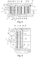
- FIGS. 5 to 8 show the inventive novel coupling, which is characterized in that in the space between the drive-side metal fins 25 and the output-side metal fins 26 now each cantilever friction plates 28 are arranged.
- FIG. 5 shows a friction plate 28 in that such a friction plate 28 can also be of multilayer construction and may consist of a core and friction linings attached on both sides.
- the invention is not limited thereto.
- the multilayer structure of a friction plate can also be replaced by a single-layer structure, the friction plate 28 then only from a plastic-reinforced or metal-fiber or carbon-reinforced paper material or another impregnable material (eg a nonwoven and / or knitted fabric and / or knitted fabric).
- the respective friction plate 28 in the receiving space 8 freewheeling automatically sets radially and axially and depending on the distance to the outer circumference of the inner disk carrier 13 or the radial distance to the inner periphery of the outer disk carrier 12 either centered in the direction of the inner disk carrier 13 automatically on this or automatically centered on the inner periphery of the outer disk carrier 12.
- the respective cantilevered friction plate 28 automatically adjusts in the receiving space 8 between the drive and driven side metal plates 25, 26 in the axial and radial direction, and only at the end of the clutch when the axial pressure force 11 on the piston. 7 is applied, the gaps 9 disappear between the mutually associated friction surfaces 32, 33, 34, 35 and the friction plate 28 transmits the torque.
- the invention is not limited to that the friction surfaces of the friction plate 28 are formed smooth and structured throughout.
- the friction surfaces 33, 34 of the respectively self-adjusting friction plate 28 are formed structured. Under such a structure is understood that at an angle to the direction of rotation oblique nubs, elevations or grooves for better dissipation of the oil flow or other liquid or gaseous heat transfer medium from the surface of the friction plate 28 are provided in the space 9 each left and right the friction plate 28 is made.
- the friction plate 28 is flat.
- the surface may be slightly wavy to allow automatic springback to the uncoupled position. It then acts in the manner of a diaphragm spring.
- a clutch-side return spring is saved, which generates a restoring force that is otherwise necessary in such couplings.
- the overall length is further minimized by the axially resiliently formed friction plate.
- FIG. 5 shows a multi-layer friction blade 28 having a core layer 30 and two outer lining layers 31 shows the FIG. 6 a single-layer structure of such a friction plate.
- FIG. 7 shows a perspective section through a coupling according to the illustration FIG. 6 where the same parts are given the same reference numerals.
- FIG. 8 shows the fully rotationally symmetrical structure of the coupling according to the invention. Starting from the teeth having a start blade 23, which rests on the inner periphery of the outer disk carrier 12 follows this friction or brake plate 28 of the invention, which adjusts freely in the space between the inner disk carrier 13 and outer disk carrier 12.
- the output-side metal plate 26 is arranged, which is with its internal teeth in a rotationally fixed, but axially displaceable engagement with the teeth of the inner disk carrier 13.
- a friction or Brake plate 28 on whose opposite side, the drive-side metal plates 25 connects.
- This has an external toothing, which is in the positive, but axially displaceable engagement with the inner periphery of the outer disk carrier 12.
Landscapes
- Engineering & Computer Science (AREA)
- General Engineering & Computer Science (AREA)
- Mechanical Engineering (AREA)
- Mechanical Operated Clutches (AREA)
- Braking Arrangements (AREA)
Applications Claiming Priority (1)
| Application Number | Priority Date | Filing Date | Title |
|---|---|---|---|
| DE102013013782.9A DE102013013782A1 (de) | 2013-08-21 | 2013-08-21 | Kupplung mit fliegenden Reiblamellen |
Publications (2)
| Publication Number | Publication Date |
|---|---|
| EP2905501A2 true EP2905501A2 (fr) | 2015-08-12 |
| EP2905501A3 EP2905501A3 (fr) | 2016-04-20 |
Family
ID=51224661
Family Applications (1)
| Application Number | Title | Priority Date | Filing Date |
|---|---|---|---|
| EP14002546.1A Withdrawn EP2905501A3 (fr) | 2013-08-21 | 2014-07-23 | Couplage doté de lamelles à friction mobiles |
Country Status (2)
| Country | Link |
|---|---|
| EP (1) | EP2905501A3 (fr) |
| DE (1) | DE102013013782A1 (fr) |
Families Citing this family (1)
| Publication number | Priority date | Publication date | Assignee | Title |
|---|---|---|---|---|
| DE102018008782A1 (de) * | 2018-11-08 | 2020-05-14 | Borgwarner Inc. | Lamelle für eine Lamellenkupplung oder -bremse, Lamellenkupplung oder -bremse mit einer solchen Lamelle und Verfahren zur Herstellung einer solchen Lamelle |
Citations (5)
| Publication number | Priority date | Publication date | Assignee | Title |
|---|---|---|---|---|
| DE619382C (de) | 1934-11-21 | 1935-09-28 | Richard Becker | Roehrenschlittschuh mit Verstaerkungseinlage |
| DE692387C (de) | 1937-08-05 | 1940-06-19 | Getriebe G M B H Deutsche | dgl. -reiblamellen |
| DE3100586A1 (de) | 1981-01-10 | 1982-08-26 | Alfred Teves Gmbh, 6000 Frankfurt | Vorrichtung zur lagerung eines scheibenfoermigen reibelements in einem traegerteil fuer eine brems- oder kupplungseinrichtung |
| DE102009039467A1 (de) | 2009-08-31 | 2011-03-03 | GM Global Technology Operations, Inc., Detroit | Doppelreibungskupplung für ein Fahrzeug |
| DE102010051446A1 (de) | 2010-07-29 | 2012-02-02 | Schaeffler Technologies Gmbh & Co. Kg | Kupplungsvorrichtung |
Family Cites Families (7)
| Publication number | Priority date | Publication date | Assignee | Title |
|---|---|---|---|---|
| DE1115997B (de) * | 1958-10-21 | 1961-10-26 | Hedin Kjelsaas | Lamellenbremse |
| DE3801911A1 (de) * | 1987-02-02 | 1988-08-11 | Volkswagen Ag | Anordnung fuer eine mehrscheiben-lamellen-kupplung oder -bremse |
| FR2662483A2 (fr) * | 1990-02-28 | 1991-11-29 | Antonov Roumen | Dispositif de transmission a rapport variable en particulier pour l'automobile. |
| FR2767166B1 (fr) * | 1997-08-05 | 1999-10-29 | Messier Bugatti | Dispositif de friction dans l'huile a disques coaxiaux |
| FR2774731A1 (fr) * | 1997-12-19 | 1999-08-13 | Antonov Automotive Europ | Disque et dispositif d'accouplement par friction, et transmission automatique ainsi equipee |
| AT507251B1 (de) * | 2008-09-05 | 2018-03-15 | Miba Frictec Gmbh | Reiblamelle |
| DE102009000431A1 (de) * | 2009-01-27 | 2010-07-29 | Kleinlein, Claus, Dr.-Ing. | Nass laufende Lamellenkupplung oder -bremse |
-
2013
- 2013-08-21 DE DE102013013782.9A patent/DE102013013782A1/de not_active Withdrawn
-
2014
- 2014-07-23 EP EP14002546.1A patent/EP2905501A3/fr not_active Withdrawn
Patent Citations (5)
| Publication number | Priority date | Publication date | Assignee | Title |
|---|---|---|---|---|
| DE619382C (de) | 1934-11-21 | 1935-09-28 | Richard Becker | Roehrenschlittschuh mit Verstaerkungseinlage |
| DE692387C (de) | 1937-08-05 | 1940-06-19 | Getriebe G M B H Deutsche | dgl. -reiblamellen |
| DE3100586A1 (de) | 1981-01-10 | 1982-08-26 | Alfred Teves Gmbh, 6000 Frankfurt | Vorrichtung zur lagerung eines scheibenfoermigen reibelements in einem traegerteil fuer eine brems- oder kupplungseinrichtung |
| DE102009039467A1 (de) | 2009-08-31 | 2011-03-03 | GM Global Technology Operations, Inc., Detroit | Doppelreibungskupplung für ein Fahrzeug |
| DE102010051446A1 (de) | 2010-07-29 | 2012-02-02 | Schaeffler Technologies Gmbh & Co. Kg | Kupplungsvorrichtung |
Also Published As
| Publication number | Publication date |
|---|---|
| DE102013013782A1 (de) | 2015-02-26 |
| EP2905501A3 (fr) | 2016-04-20 |
Similar Documents
| Publication | Publication Date | Title |
|---|---|---|
| EP2185833B1 (fr) | Pièce de friction comprenant une rainure périphérique en zigzag ou ondulée pratiquée dans la surface de friction | |
| DE69708447T2 (de) | Nasse Reibscheibenkupplung | |
| DE3529234C2 (fr) | ||
| DE102009057353A1 (de) | Lamellenkupplung mit einer Federeinrichtung | |
| WO1987003348A1 (fr) | Embrayage a disques | |
| DE60214995T2 (de) | Nasskupplung oder Reibscheibebremse | |
| DE102011006027A1 (de) | Ölzuführnabe für eine nasslaufende Doppelkupplung | |
| DE102008063662A1 (de) | Lamelle für eine reibschlüssig arbeitende Einrichtung und reibschlüssig arbeitende Einrichtung mit einer solchen Lamelle | |
| EP2843253A2 (fr) | Disque de friction ou de freinage pour embrayages | |
| EP1525407A1 (fr) | Ensemble embrayage | |
| DE102007027120A1 (de) | Kupplung | |
| DE102013220531A1 (de) | Reibschaltelement | |
| DE3426460C1 (de) | Regelkupplung | |
| DE112011100684T5 (de) | Scheibenelement und mit Scheibenelement versehene Bremsvorrichtung | |
| EP3217031A1 (fr) | Embrayage à disque | |
| DE102012020820B4 (de) | Differenzgeschwindigkeitsabhängige Bremse | |
| DE19848582A1 (de) | Selbstverstärkende Reibungskupplung | |
| DE102004058872B4 (de) | Doppelkupplung | |
| EP2905501A2 (fr) | Couplage doté de lamelles à friction mobiles | |
| EP1521005B1 (fr) | Unité d'embrayage et/ou de frein | |
| DE102017119079A1 (de) | Doppelschlingfeder, Rotationseinrichtung und zu aktuierendes System | |
| WO2018077349A1 (fr) | Disque pour embrayage à friction humide | |
| DE69610936T2 (de) | Kupplungseinrichtung | |
| EP3179124B1 (fr) | Lamelle de friction | |
| DE102017001844A1 (de) | Kopplungsvorrichtung für eine Lamellenkupplung und Lamellenkupplung mit einer solchen Kopplungsvorrichtung |
Legal Events
| Date | Code | Title | Description |
|---|---|---|---|
| PUAI | Public reference made under article 153(3) epc to a published international application that has entered the european phase |
Free format text: ORIGINAL CODE: 0009012 |
|
| AK | Designated contracting states |
Kind code of ref document: A2 Designated state(s): AL AT BE BG CH CY CZ DE DK EE ES FI FR GB GR HR HU IE IS IT LI LT LU LV MC MK MT NL NO PL PT RO RS SE SI SK SM TR |
|
| AX | Request for extension of the european patent |
Extension state: BA ME |
|
| PUAL | Search report despatched |
Free format text: ORIGINAL CODE: 0009013 |
|
| AK | Designated contracting states |
Kind code of ref document: A3 Designated state(s): AL AT BE BG CH CY CZ DE DK EE ES FI FR GB GR HR HU IE IS IT LI LT LU LV MC MK MT NL NO PL PT RO RS SE SI SK SM TR |
|
| AX | Request for extension of the european patent |
Extension state: BA ME |
|
| RIC1 | Information provided on ipc code assigned before grant |
Ipc: F16D 69/00 20060101AFI20160317BHEP Ipc: F16D 13/52 20060101ALI20160317BHEP Ipc: F16D 13/68 20060101ALI20160317BHEP |
|
| STAA | Information on the status of an ep patent application or granted ep patent |
Free format text: STATUS: THE APPLICATION HAS BEEN WITHDRAWN |
|
| 18W | Application withdrawn |
Effective date: 20160527 |