EP2905545B1 - Elektrische Ofenanlage - Google Patents
Elektrische Ofenanlage Download PDFInfo
- Publication number
- EP2905545B1 EP2905545B1 EP15151862.8A EP15151862A EP2905545B1 EP 2905545 B1 EP2905545 B1 EP 2905545B1 EP 15151862 A EP15151862 A EP 15151862A EP 2905545 B1 EP2905545 B1 EP 2905545B1
- Authority
- EP
- European Patent Office
- Prior art keywords
- cavity
- vent
- closure means
- steam
- electric oven
- Prior art date
- Legal status (The legal status is an assumption and is not a legal conclusion. Google has not performed a legal analysis and makes no representation as to the accuracy of the status listed.)
- Not-in-force
Links
Images


Classifications
-
- F—MECHANICAL ENGINEERING; LIGHTING; HEATING; WEAPONS; BLASTING
- F24—HEATING; RANGES; VENTILATING
- F24C—DOMESTIC STOVES OR RANGES ; DETAILS OF DOMESTIC STOVES OR RANGES, OF GENERAL APPLICATION
- F24C15/00—Details
- F24C15/20—Removing cooking fumes
- F24C15/2007—Removing cooking fumes from oven cavities
Definitions
- This invention relates to improvements in electric oven assemblies, in particular to fan assisted electric ovens.
- Electric ovens are well known, and in general comprise an oven cavity, with walls typically formed from pressed metal sheets and a door, that is surrounded by insulation material contained within a main body.
- the main body may contain more than one such cavity, and is sometimes topped with a heating plate to allow food to be cooked in pans or trays placed on the heating plate.
- the temperature inside the cavity it raised using one or more electric heating elements that are located inside the cavity or within a chamber that is connected to cavity, or even in the walls of the cavity.
- a fan helps to circulate the heated air around the cavity to minimise the generation of localised hot spots.
- an electric oven can achieve high levels of efficiency
- Common areas are the seal of the door to the oven walls and production holes, for instance at the corners of pressed sheets used to form the walls.
- a side effect of this sealing is that steam produced in the cooking process is trapped in the cavity. On opening the door this steam can suddenly "burst" out which could burn the user if care is not taken.
- commonly cooked foods such as frozen oven chips contain large amounts of water and will produce correspondingly large amounts of steam during cooking.
- EP 0 598 211 A1 discloses an oven according to the preamble of claim 1.
- An object of the present invention is to ameliorate the problems associated with well sealed oven cavities.
- an electric oven assembly comprising:
- the vent may comprise a hollow channel, such as a pipe, that has one open end in communication with the inside of the cavity and an opposite open end that is in communication with the air outside of the cavity.
- the pipe may be located outside of the cavity.
- the vent may simply comprise an opening cut into one or more walls (side, base or top) of the oven cavity through which steam can pass and which is selectively blocked by the closure means.
- the oven may comprise a main body having a base, sides and front and back walls, the cavity and insulation being located inside the main body, the free end of the vent being positioned so that the escaping steam is able to vent outside of the main body.
- the vent may be arranged so that steam escapes the main body at a safe location away from the door of the cavity so that escaping steam does not inconvenience a user, e.g. at the rear of the chassis towards the top of the oven.
- the closure means is adapted to open automatically when the temperature inside the cavity or the vent reaches a first predefined temperature and to close automatically when the temperature drops to a second predefined temperature.
- the first and second predefined temperatures may be same or the first may be higher than the second giving a degree of hysteresis.
- the closure means may comprise a variable throttle. This may have two positions, fully open and fully closed and move between the two rapidly. Alternatively it may be capable of holding any position between fully open and fully closed to provide fine control of the amount that the vent is open.
- the throttle may comprise a valve such as a slide valve or butterfly valve. It may comprise a flap which moves relative to the vent.
- the closure means may include an actuator that causes the throttle or choke to move thereby to open and close the closure means.
- the actuator may comprise a bimetallic strip that is exposed to the heated air in the cavity or vent. This will enable the vent to open and close automatically.
- the closure means may alternatively of additionally be adapted to be moved from an open to a closed position and vice versa manually.
- a user operable means may be provided which can be pushed or pulled to move the flap.
- the closure may be powered and a means for allowing the user to cause the power to move the closure may be provided.
- a solenoid may be provided that is operated when a user presses a button or other operating means.
- the closure means may open and close in response to a signal from a timer. For instance, when the oven is first switched on it may be assumed that it will take a defined time to reach a temperature at which steam may be produced, and during until that time has elapsed the closure means may be closed, opening after the time has elapsed. This time may be set as a function of the power applied to the heating element or elements and perhaps also the size of the cavity.
- closure means operates automatically, it may be possible to manually override it.
- two throttles may be provided one operating automatically and the other manually.
- the closure means may be located inside the cavity or outside of the cavity.
- the oven may include a fan which in use causes the air inside the cavity to circulate around the cavity.
- the oven may include a control circuit that enables a user to set the temperature within the cavity by controlling the flow of current from a power supply through the at least one heating element.
- the oven may include more than one cavity, in which case each may be provided with a respective vent and an associated closure means. This allows each cavity to be individually vented. This will allow more economical operation of multiple ovens by only venting each cavity when needed or wanted.
- the electric oven assembly may comprise a part of a range style cooker, which may include multiple oven assemblies and a hotplate. It may form part of other styles of cooker, for instance those intended to be built into kitchen furniture are referred to commonly as integrated appliances.
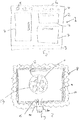
- a range style cooker 1 comprises a main body 2 or chassis which is generally box like with left and right walls, a rear wall and a front wall, all formed as pressed steel panels.
- the base of the chassis is supported on adjustable legs (not shown) hidden behind a plinth 3.
- a control panel 4 which carries knobs 5 enabling a user to operate the oven.
- the top of the chassis is finished with a hotplate 6 having multiple heating zones.
- Range style cookers of this form are widely known, and typically have a width of between 60 and 150cm, with a depth of around 60cm for compatibility with standard unit sizes in a fitted style kitchen.
- the main body 2 of the appliance contains three oven cavities of differing shapes and internal volumes, each of which is located behind an insulated door 7 that is sealed around its edge to an opening in the front wall of the main body.
- the cavity 8 comprises a box 9 made up of substantially rectangular pressed steel walls.
- the box 9 is surrounded by an insulating material 10 such as mineral wool.
- Within the rear wall of the cavity 9 is a circular opening 11 with an electric fan 12 and behind the fan is a heating element 13.
- the element 13 is a resistive heating element which heats the surrounding air as current is passed through it, and the fan blows this heated air around the cavity.
- the oven in this configuration is a so called fan assisted electric oven.
- the cavity 9 is sealed apart from an opening at the front which is in register with the door, and a vent 14 which is connected to an opening in a wall of the cavity.
- the vent is separate from the door, by which we mean that air can pass through the vent even when the door is closed.
- the vent is in the base but it could be located in any of the walls and a preferred location might be towards the top left area (when viewed looking into the cavity) of the oven back wall.
- the vent in this example comprises a pipe 14 that extends away from the opening 15, but could simply comprise the opening with the pipe being omitted.
- the function of the pipe is to guide hot air and steam that passes through the opening towards an outlet in the main body.
- the vent is provided with a closure means 16. This is shown in general in Figure 2 and Figures 3 to 5 of the accompanying drawings show three possible different arrangements of closure means. In each case the closure means is located inside the oven cavity where it can be easily accessed for maintance, inspection or replacement as required.
- the closure means 16 provides an important function of preventing air from escaping through the vent at times when there is unlikely to be any steam present in the oven cavity, while being able to open to allow steam to escape when needed.
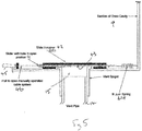
- Figure 3 shows a first closure means 20 that corresponds with the opening 15. It comprises a plunger type valve 21 that is terminated at one end with a pad 22 that rests against the side walls of the vent opening when the temperature in the cavity is low (i.e. below about 90 degrees). The sides walls define the seat of the valve.
- the pad 22 is connected to a valve stem 23 that is surrounded by a spring 24.
- the spring 24 at one end presses on the rear of the pad 22, opposed to the opening, and at the other presses on a support bracket 25. The spring 24 therefore acts to press the valve pad onto the side wall of the opening to keep it firmly closed.
- the stem 23 passes through an opening in the support bracket, and the end of the stem opposed to the pad is provided with a stopper 26 that has a larger width than the stem. Between the stopper 26 and the support bracket 25 are a stack of bimetallic washers 27.
- the washers function as an actuator that cause the pad to be pulled away from the opening as the temperature exceeds a predetermined value of, perhaps, 90 degrees or so.
- Each washer 27 comprises a bimetallic disk that will deform as the temperature rises, and this deformation of the washers effectively varies the height of the stack.
- FIG 4 shows an alternative closure means 30.
- This comprises a throttle comprising a pad 31 that rests against the side wall of the opening 15 in the cavity 9.
- a lever or arm 32 extends from the pad to one end of a bimetallic strip 33.
- the other end of the bimetallic strip 33 is fixed to a support bracket 34.
- the pad closes the opening 15.
- a predefined threshold of, say, 90 degrees the bimetallic strip 33 will start to bend and this causes the pad 31 to move away from the opening. This is shown in Figure 4(b) .
- Figure 5 shows an alternative arrangement of a closure means 40. This differs from those of Figure 3 and 4 in that the actuator is no longer automatic, requiring manual intervention to move the closure means from a closed condition to an open condition.
- the closure means 40 comprises a slide plate 41 that is located in guide rails 42.
- the slide plate has a hole 43 in it that is complimentary to the opening 15 and can be slid along the rails 42 between a position in which the plate closes off the opening 15 and a position in the hole 43 is aligned with the opening 15 and thus allows steam to pass through.
- One end of the plate 41 is secured to a spring 44 that tends to pull the plate to the closed position, and the other end of the plate 41 is connected to a handle 45 through a cable 46. An operator can manually open and close the vent by pulling and pushing the handle.
Landscapes
- Engineering & Computer Science (AREA)
- Chemical & Material Sciences (AREA)
- Combustion & Propulsion (AREA)
- Mechanical Engineering (AREA)
- General Engineering & Computer Science (AREA)
- Cookers (AREA)
Claims (8)
- Elektrische Ofenanlage, umfassend: einen Ofenhohlraum (8) mit Wänden und einer Tür, den Hohlraum umgebendes Dämmmaterial (10), ein oder mehrere elektrische Heizelemente (13), die betrieben werden können, um das Innere des Hohlraums zu heizen; eine Lüftungsöffnung (14),
die in Verbindung mit dem Inneren des Hohlraums ist und durch die Dampf passieren kann, der im Inneren des Hohlraums zu Zeiten erzeugt wurde, wenn die Tür geschlossen ist; und einen Verschluss (16), der das Passieren des Dampfs durch die Lüftungsöffnung steuert, wobei das Verschlussmittel im geschlossenen Zustand Lüftungsöffnung abdichtet, um die Freisetzung von heißer Luft und Dampf aus dem Hohlraum zu verhindern, und das Verschlussmittel im offenen Zustand das Entweichen von heißer Luft und Dampf aus dem Hohlraum zulässt, dadurch gekennzeichnet, dass das Verschlussmittel angepasst ist, um sich automatisch zu öffnen, wenn die Temperatur im Inneren des Hohlraums oder der Belüftungsöffnung eine erste vordefinierte Temperatur erreicht, und sich automatisch zu schließen, wenn die Temperatur auf eine zweite vordefinierte Temperatur fällt. - Elektrische Ofenanlage nach Anspruch 1, wobei die Belüftungsöffnung einen Hohlkanal, wie beispielsweise ein Rohr, umfasst, der ein offenes Ende in Verbindung mit dem Inneren des Hohlraums und ein entgegengesetztes offenes Ende in Verbindung mit der Luft außerhalb des Hohlraums aufweist, wobei das Verschlussmittel selektiv einen Teil des Kanals blockiert.
- Elektrische Ofenanlage nach Anspruch 1, wobei die Belüftungsöffnung eine in eine oder mehrere Wände (Seite, Unterseite oder Oberseite) des Ofenhohlraums geschnittene Öffnung umfasst, durch die Dampf passieren kann und die selektiv durch das Verschlussmittel blockiert wird.
- Elektrische Ofenanlage nach einem der vorstehenden Ansprüche, wobei das Verschlussmittel eine verstellbare Drosselvorrichtung umfasst.
- Elektrische Ofenanlage nach Anspruch 4, wobei die verstellbare Drosselvorrichtung ein Schieberventil oder ein Drosselventil oder eine Drosselklappe umfasst.
- Elektrische Ofenanlage nach Anspruch 4 oder Anspruch 5, wobei das Verschlussmittel ein Stellglied beinhaltet, das bewirkt, dass sich die Drosselvorrichtung oder Drossel bewegt, um dadurch das Verschlussmittel zu öffnen und zu schließen.
- Elektrische Ofenanlage nach Anspruch 6, wobei das Stellglied einen Bimetallstreifen (33) umfasst, der der geheizten Luft im Hohlraum oder der Entlüftungsöffnung ausgesetzt ist.
- Elektrische Ofenanlage nach einem der vorangehenden Ansprüche, wobei das Verschlussmittel manuell von einer offenen in eine geschlossene Position und umgekehrt bewegt werden kann.
Applications Claiming Priority (1)
| Application Number | Priority Date | Filing Date | Title |
|---|---|---|---|
| GBGB1400934.4A GB201400934D0 (en) | 2014-01-20 | 2014-01-20 | An electric oven assembly |
Publications (2)
| Publication Number | Publication Date |
|---|---|
| EP2905545A1 EP2905545A1 (de) | 2015-08-12 |
| EP2905545B1 true EP2905545B1 (de) | 2020-06-10 |
Family
ID=50239192
Family Applications (1)
| Application Number | Title | Priority Date | Filing Date |
|---|---|---|---|
| EP15151862.8A Not-in-force EP2905545B1 (de) | 2014-01-20 | 2015-01-20 | Elektrische Ofenanlage |
Country Status (2)
| Country | Link |
|---|---|
| EP (1) | EP2905545B1 (de) |
| GB (1) | GB201400934D0 (de) |
Families Citing this family (1)
| Publication number | Priority date | Publication date | Assignee | Title |
|---|---|---|---|---|
| TR201610863A2 (tr) * | 2016-08-03 | 2018-02-21 | Arcelik As | Havalandirmasi ve buhar çekme özelli̇ği̇ i̇yi̇leşti̇ri̇len firin |
Family Cites Families (4)
| Publication number | Priority date | Publication date | Assignee | Title |
|---|---|---|---|---|
| JPS61186726A (ja) * | 1985-02-15 | 1986-08-20 | Toshiba Corp | 調理器 |
| DE3839657C2 (de) * | 1988-11-24 | 1993-11-18 | Miele & Cie | Luftführungssystem für einen Backofen |
| GB2258126B (en) * | 1991-07-20 | 1995-03-22 | Creda Ltd | Oven with combined microwave and other heating sources |
| DE4238660C2 (de) * | 1992-11-16 | 1994-09-01 | Bosch Siemens Hausgeraete | Backofen, insbesondere mit einer Einrichtung für pyrolytische Selbstreinigung |
-
2014
- 2014-01-20 GB GBGB1400934.4A patent/GB201400934D0/en not_active Ceased
-
2015
- 2015-01-20 EP EP15151862.8A patent/EP2905545B1/de not_active Not-in-force
Non-Patent Citations (1)
| Title |
|---|
| None * |
Also Published As
| Publication number | Publication date |
|---|---|
| GB201400934D0 (en) | 2014-03-05 |
| EP2905545A1 (de) | 2015-08-12 |
Similar Documents
| Publication | Publication Date | Title |
|---|---|---|
| US9803873B2 (en) | Oven range appliance | |
| US20120152223A1 (en) | Baking device and method for operating a baking device | |
| AU2009282897B2 (en) | Hybrid broil system-electric broil element | |
| AU2018318597B2 (en) | Heating apparatus and cooking apparatus including same | |
| WO2017116352A1 (en) | An oven comprising a water tank | |
| KR101443456B1 (ko) | 히터의 높낮이 조절식 양면 전기 구이 그릴 | |
| CN114945306A (zh) | 用于高热烹饪的烤箱器具和方法 | |
| EP2905545A1 (de) | Elektrische Ofenanlage | |
| EP2037180A1 (de) | Einbau-Küchengerät | |
| CN108143258B (zh) | 烹饪器具 | |
| EP1818620B1 (de) | Backofen mit einem Backwagen mit integriertem Heizelement und Grillrosten | |
| US6965094B1 (en) | Controlled heat steamer | |
| EP2963994A1 (de) | Verbesserungen im zusammenhang mit elektroherden | |
| KR101594311B1 (ko) | 전기 압력 조리기 | |
| JP7731283B2 (ja) | オーブン調理システム、加熱調理器及びオーブン調理容器 | |
| JP2003135284A (ja) | サツマイモ等食品加熱調理保温装置 | |
| WO2014102112A1 (en) | An oven comprising an oven burner and a grill burner that are prevented from being operated simultaneously | |
| US20230105606A1 (en) | Oven appliance having a modular trim assembly for a hidden heating assembly | |
| US1052894A (en) | Electrically-heated stove. | |
| KR100783242B1 (ko) | 조리기기 | |
| US12298013B2 (en) | Oven appliance and methods of state-contingent operation | |
| CN111110000B (zh) | 烹饪器具和用于烹饪器具的控制方法 | |
| JP2024041294A (ja) | 加熱調理器 | |
| EP2638328B1 (de) | Gargerät und verfahren zum betreiben eines gargeräts mit verkürzter garzeit | |
| EP2217037A1 (de) | Kombinierter Ofen zum Kochen, Erwärmen und Auftauen von gefrorenen oder frischen Nahrungsmitteln, insbesondere zum Erwärmen von Sandwiches |
Legal Events
| Date | Code | Title | Description |
|---|---|---|---|
| PUAI | Public reference made under article 153(3) epc to a published international application that has entered the european phase |
Free format text: ORIGINAL CODE: 0009012 |
|
| AK | Designated contracting states |
Kind code of ref document: A1 Designated state(s): AL AT BE BG CH CY CZ DE DK EE ES FI FR GB GR HR HU IE IS IT LI LT LU LV MC MK MT NL NO PL PT RO RS SE SI SK SM TR |
|
| AX | Request for extension of the european patent |
Extension state: BA ME |
|
| 17P | Request for examination filed |
Effective date: 20160212 |
|
| RBV | Designated contracting states (corrected) |
Designated state(s): AL AT BE BG CH CY CZ DE DK EE ES FI FR GB GR HR HU IE IS IT LI LT LU LV MC MK MT NL NO PL PT RO RS SE SI SK SM TR |
|
| GRAP | Despatch of communication of intention to grant a patent |
Free format text: ORIGINAL CODE: EPIDOSNIGR1 |
|
| STAA | Information on the status of an ep patent application or granted ep patent |
Free format text: STATUS: GRANT OF PATENT IS INTENDED |
|
| INTG | Intention to grant announced |
Effective date: 20190426 |
|
| GRAJ | Information related to disapproval of communication of intention to grant by the applicant or resumption of examination proceedings by the epo deleted |
Free format text: ORIGINAL CODE: EPIDOSDIGR1 |
|
| GRAJ | Information related to disapproval of communication of intention to grant by the applicant or resumption of examination proceedings by the epo deleted |
Free format text: ORIGINAL CODE: EPIDOSDIGR1 |
|
| GRAP | Despatch of communication of intention to grant a patent |
Free format text: ORIGINAL CODE: EPIDOSNIGR1 |
|
| STAA | Information on the status of an ep patent application or granted ep patent |
Free format text: STATUS: REQUEST FOR EXAMINATION WAS MADE |
|
| GRAP | Despatch of communication of intention to grant a patent |
Free format text: ORIGINAL CODE: EPIDOSNIGR1 |
|
| STAA | Information on the status of an ep patent application or granted ep patent |
Free format text: STATUS: GRANT OF PATENT IS INTENDED |
|
| INTG | Intention to grant announced |
Effective date: 20200226 |
|
| RAP1 | Party data changed (applicant data changed or rights of an application transferred) |
Owner name: AGA RANGEMASTER LIMITED |
|
| GRAS | Grant fee paid |
Free format text: ORIGINAL CODE: EPIDOSNIGR3 |
|
| GRAA | (expected) grant |
Free format text: ORIGINAL CODE: 0009210 |
|
| STAA | Information on the status of an ep patent application or granted ep patent |
Free format text: STATUS: THE PATENT HAS BEEN GRANTED |
|
| AK | Designated contracting states |
Kind code of ref document: B1 Designated state(s): AL AT BE BG CH CY CZ DE DK EE ES FI FR GB GR HR HU IE IS IT LI LT LU LV MC MK MT NL NO PL PT RO RS SE SI SK SM TR |
|
| REG | Reference to a national code |
Ref country code: GB Ref legal event code: FG4D |
|
| REG | Reference to a national code |
Ref country code: AT Ref legal event code: REF Ref document number: 1279498 Country of ref document: AT Kind code of ref document: T Effective date: 20200615 Ref country code: CH Ref legal event code: EP |
|
| REG | Reference to a national code |
Ref country code: DE Ref legal event code: R096 Ref document number: 602015053992 Country of ref document: DE |
|
| REG | Reference to a national code |
Ref country code: IE Ref legal event code: FG4D |
|
| REG | Reference to a national code |
Ref country code: SE Ref legal event code: TRGR |
|
| REG | Reference to a national code |
Ref country code: NL Ref legal event code: FP |
|
| REG | Reference to a national code |
Ref country code: LT Ref legal event code: MG4D |
|
| PG25 | Lapsed in a contracting state [announced via postgrant information from national office to epo] |
Ref country code: FI Free format text: LAPSE BECAUSE OF FAILURE TO SUBMIT A TRANSLATION OF THE DESCRIPTION OR TO PAY THE FEE WITHIN THE PRESCRIBED TIME-LIMIT Effective date: 20200610 Ref country code: GR Free format text: LAPSE BECAUSE OF FAILURE TO SUBMIT A TRANSLATION OF THE DESCRIPTION OR TO PAY THE FEE WITHIN THE PRESCRIBED TIME-LIMIT Effective date: 20200911 Ref country code: NO Free format text: LAPSE BECAUSE OF FAILURE TO SUBMIT A TRANSLATION OF THE DESCRIPTION OR TO PAY THE FEE WITHIN THE PRESCRIBED TIME-LIMIT Effective date: 20200910 Ref country code: LT Free format text: LAPSE BECAUSE OF FAILURE TO SUBMIT A TRANSLATION OF THE DESCRIPTION OR TO PAY THE FEE WITHIN THE PRESCRIBED TIME-LIMIT Effective date: 20200610 |
|
| PG25 | Lapsed in a contracting state [announced via postgrant information from national office to epo] |
Ref country code: BG Free format text: LAPSE BECAUSE OF FAILURE TO SUBMIT A TRANSLATION OF THE DESCRIPTION OR TO PAY THE FEE WITHIN THE PRESCRIBED TIME-LIMIT Effective date: 20200910 Ref country code: RS Free format text: LAPSE BECAUSE OF FAILURE TO SUBMIT A TRANSLATION OF THE DESCRIPTION OR TO PAY THE FEE WITHIN THE PRESCRIBED TIME-LIMIT Effective date: 20200610 Ref country code: HR Free format text: LAPSE BECAUSE OF FAILURE TO SUBMIT A TRANSLATION OF THE DESCRIPTION OR TO PAY THE FEE WITHIN THE PRESCRIBED TIME-LIMIT Effective date: 20200610 Ref country code: LV Free format text: LAPSE BECAUSE OF FAILURE TO SUBMIT A TRANSLATION OF THE DESCRIPTION OR TO PAY THE FEE WITHIN THE PRESCRIBED TIME-LIMIT Effective date: 20200610 |
|
| REG | Reference to a national code |
Ref country code: AT Ref legal event code: MK05 Ref document number: 1279498 Country of ref document: AT Kind code of ref document: T Effective date: 20200610 |
|
| PG25 | Lapsed in a contracting state [announced via postgrant information from national office to epo] |
Ref country code: AL Free format text: LAPSE BECAUSE OF FAILURE TO SUBMIT A TRANSLATION OF THE DESCRIPTION OR TO PAY THE FEE WITHIN THE PRESCRIBED TIME-LIMIT Effective date: 20200610 |
|
| PG25 | Lapsed in a contracting state [announced via postgrant information from national office to epo] |
Ref country code: EE Free format text: LAPSE BECAUSE OF FAILURE TO SUBMIT A TRANSLATION OF THE DESCRIPTION OR TO PAY THE FEE WITHIN THE PRESCRIBED TIME-LIMIT Effective date: 20200610 Ref country code: AT Free format text: LAPSE BECAUSE OF FAILURE TO SUBMIT A TRANSLATION OF THE DESCRIPTION OR TO PAY THE FEE WITHIN THE PRESCRIBED TIME-LIMIT Effective date: 20200610 Ref country code: IT Free format text: LAPSE BECAUSE OF FAILURE TO SUBMIT A TRANSLATION OF THE DESCRIPTION OR TO PAY THE FEE WITHIN THE PRESCRIBED TIME-LIMIT Effective date: 20200610 Ref country code: SM Free format text: LAPSE BECAUSE OF FAILURE TO SUBMIT A TRANSLATION OF THE DESCRIPTION OR TO PAY THE FEE WITHIN THE PRESCRIBED TIME-LIMIT Effective date: 20200610 Ref country code: PT Free format text: LAPSE BECAUSE OF FAILURE TO SUBMIT A TRANSLATION OF THE DESCRIPTION OR TO PAY THE FEE WITHIN THE PRESCRIBED TIME-LIMIT Effective date: 20201012 Ref country code: ES Free format text: LAPSE BECAUSE OF FAILURE TO SUBMIT A TRANSLATION OF THE DESCRIPTION OR TO PAY THE FEE WITHIN THE PRESCRIBED TIME-LIMIT Effective date: 20200610 Ref country code: RO Free format text: LAPSE BECAUSE OF FAILURE TO SUBMIT A TRANSLATION OF THE DESCRIPTION OR TO PAY THE FEE WITHIN THE PRESCRIBED TIME-LIMIT Effective date: 20200610 Ref country code: CZ Free format text: LAPSE BECAUSE OF FAILURE TO SUBMIT A TRANSLATION OF THE DESCRIPTION OR TO PAY THE FEE WITHIN THE PRESCRIBED TIME-LIMIT Effective date: 20200610 |
|
| PG25 | Lapsed in a contracting state [announced via postgrant information from national office to epo] |
Ref country code: IS Free format text: LAPSE BECAUSE OF FAILURE TO SUBMIT A TRANSLATION OF THE DESCRIPTION OR TO PAY THE FEE WITHIN THE PRESCRIBED TIME-LIMIT Effective date: 20201010 Ref country code: SK Free format text: LAPSE BECAUSE OF FAILURE TO SUBMIT A TRANSLATION OF THE DESCRIPTION OR TO PAY THE FEE WITHIN THE PRESCRIBED TIME-LIMIT Effective date: 20200610 Ref country code: PL Free format text: LAPSE BECAUSE OF FAILURE TO SUBMIT A TRANSLATION OF THE DESCRIPTION OR TO PAY THE FEE WITHIN THE PRESCRIBED TIME-LIMIT Effective date: 20200610 |
|
| REG | Reference to a national code |
Ref country code: DE Ref legal event code: R097 Ref document number: 602015053992 Country of ref document: DE |
|
| PLBE | No opposition filed within time limit |
Free format text: ORIGINAL CODE: 0009261 |
|
| STAA | Information on the status of an ep patent application or granted ep patent |
Free format text: STATUS: NO OPPOSITION FILED WITHIN TIME LIMIT |
|
| PG25 | Lapsed in a contracting state [announced via postgrant information from national office to epo] |
Ref country code: DK Free format text: LAPSE BECAUSE OF FAILURE TO SUBMIT A TRANSLATION OF THE DESCRIPTION OR TO PAY THE FEE WITHIN THE PRESCRIBED TIME-LIMIT Effective date: 20200610 |
|
| 26N | No opposition filed |
Effective date: 20210311 |
|
| PG25 | Lapsed in a contracting state [announced via postgrant information from national office to epo] |
Ref country code: SI Free format text: LAPSE BECAUSE OF FAILURE TO SUBMIT A TRANSLATION OF THE DESCRIPTION OR TO PAY THE FEE WITHIN THE PRESCRIBED TIME-LIMIT Effective date: 20200610 |
|
| PG25 | Lapsed in a contracting state [announced via postgrant information from national office to epo] |
Ref country code: MC Free format text: LAPSE BECAUSE OF FAILURE TO SUBMIT A TRANSLATION OF THE DESCRIPTION OR TO PAY THE FEE WITHIN THE PRESCRIBED TIME-LIMIT Effective date: 20200610 |
|
| REG | Reference to a national code |
Ref country code: CH Ref legal event code: PL |
|
| PG25 | Lapsed in a contracting state [announced via postgrant information from national office to epo] |
Ref country code: LU Free format text: LAPSE BECAUSE OF NON-PAYMENT OF DUE FEES Effective date: 20210120 |
|
| REG | Reference to a national code |
Ref country code: BE Ref legal event code: MM Effective date: 20210131 |
|
| PG25 | Lapsed in a contracting state [announced via postgrant information from national office to epo] |
Ref country code: CH Free format text: LAPSE BECAUSE OF NON-PAYMENT OF DUE FEES Effective date: 20210131 Ref country code: LI Free format text: LAPSE BECAUSE OF NON-PAYMENT OF DUE FEES Effective date: 20210131 |
|
| PG25 | Lapsed in a contracting state [announced via postgrant information from national office to epo] |
Ref country code: IE Free format text: LAPSE BECAUSE OF NON-PAYMENT OF DUE FEES Effective date: 20210120 |
|
| PGFP | Annual fee paid to national office [announced via postgrant information from national office to epo] |
Ref country code: GB Payment date: 20211220 Year of fee payment: 8 |
|
| PGFP | Annual fee paid to national office [announced via postgrant information from national office to epo] |
Ref country code: DE Payment date: 20220107 Year of fee payment: 8 |
|
| PGFP | Annual fee paid to national office [announced via postgrant information from national office to epo] |
Ref country code: SE Payment date: 20220113 Year of fee payment: 8 Ref country code: NL Payment date: 20220107 Year of fee payment: 8 Ref country code: FR Payment date: 20220111 Year of fee payment: 8 |
|
| PG25 | Lapsed in a contracting state [announced via postgrant information from national office to epo] |
Ref country code: BE Free format text: LAPSE BECAUSE OF NON-PAYMENT OF DUE FEES Effective date: 20210131 |
|
| PG25 | Lapsed in a contracting state [announced via postgrant information from national office to epo] |
Ref country code: HU Free format text: LAPSE BECAUSE OF FAILURE TO SUBMIT A TRANSLATION OF THE DESCRIPTION OR TO PAY THE FEE WITHIN THE PRESCRIBED TIME-LIMIT; INVALID AB INITIO Effective date: 20150120 |
|
| PG25 | Lapsed in a contracting state [announced via postgrant information from national office to epo] |
Ref country code: CY Free format text: LAPSE BECAUSE OF FAILURE TO SUBMIT A TRANSLATION OF THE DESCRIPTION OR TO PAY THE FEE WITHIN THE PRESCRIBED TIME-LIMIT Effective date: 20200610 |
|
| REG | Reference to a national code |
Ref country code: DE Ref legal event code: R119 Ref document number: 602015053992 Country of ref document: DE |
|
| REG | Reference to a national code |
Ref country code: SE Ref legal event code: EUG |
|
| REG | Reference to a national code |
Ref country code: NL Ref legal event code: MM Effective date: 20230201 |
|
| GBPC | Gb: european patent ceased through non-payment of renewal fee |
Effective date: 20230120 |
|
| PG25 | Lapsed in a contracting state [announced via postgrant information from national office to epo] |
Ref country code: SE Free format text: LAPSE BECAUSE OF NON-PAYMENT OF DUE FEES Effective date: 20230121 Ref country code: NL Free format text: LAPSE BECAUSE OF NON-PAYMENT OF DUE FEES Effective date: 20230201 Ref country code: GB Free format text: LAPSE BECAUSE OF NON-PAYMENT OF DUE FEES Effective date: 20230120 Ref country code: DE Free format text: LAPSE BECAUSE OF NON-PAYMENT OF DUE FEES Effective date: 20230801 |
|
| PG25 | Lapsed in a contracting state [announced via postgrant information from national office to epo] |
Ref country code: FR Free format text: LAPSE BECAUSE OF NON-PAYMENT OF DUE FEES Effective date: 20230131 |
|
| PG25 | Lapsed in a contracting state [announced via postgrant information from national office to epo] |
Ref country code: MK Free format text: LAPSE BECAUSE OF FAILURE TO SUBMIT A TRANSLATION OF THE DESCRIPTION OR TO PAY THE FEE WITHIN THE PRESCRIBED TIME-LIMIT Effective date: 20200610 |
|
| PG25 | Lapsed in a contracting state [announced via postgrant information from national office to epo] |
Ref country code: MT Free format text: LAPSE BECAUSE OF FAILURE TO SUBMIT A TRANSLATION OF THE DESCRIPTION OR TO PAY THE FEE WITHIN THE PRESCRIBED TIME-LIMIT Effective date: 20200610 |
|
| PG25 | Lapsed in a contracting state [announced via postgrant information from national office to epo] |
Ref country code: TR Free format text: LAPSE BECAUSE OF FAILURE TO SUBMIT A TRANSLATION OF THE DESCRIPTION OR TO PAY THE FEE WITHIN THE PRESCRIBED TIME-LIMIT Effective date: 20200610 |