EP2905638B1 - Fibre optique et dispositif laser à fibre l'utilisant - Google Patents
Fibre optique et dispositif laser à fibre l'utilisant Download PDFInfo
- Publication number
- EP2905638B1 EP2905638B1 EP13844427.8A EP13844427A EP2905638B1 EP 2905638 B1 EP2905638 B1 EP 2905638B1 EP 13844427 A EP13844427 A EP 13844427A EP 2905638 B1 EP2905638 B1 EP 2905638B1
- Authority
- EP
- European Patent Office
- Prior art keywords
- light beam
- region
- mode
- optical fiber
- young
- Prior art date
- Legal status (The legal status is an assumption and is not a legal conclusion. Google has not performed a legal analysis and makes no representation as to the accuracy of the status listed.)
- Active
Links
Images


Classifications
-
- G—PHYSICS
- G02—OPTICS
- G02B—OPTICAL ELEMENTS, SYSTEMS OR APPARATUS
- G02B6/00—Light guides; Structural details of arrangements comprising light guides and other optical elements, e.g. couplings
- G02B6/02—Optical fibres with cladding with or without a coating
- G02B6/02047—Dual mode fibre
-
- G—PHYSICS
- G02—OPTICS
- G02B—OPTICAL ELEMENTS, SYSTEMS OR APPARATUS
- G02B6/00—Light guides; Structural details of arrangements comprising light guides and other optical elements, e.g. couplings
- G02B6/02—Optical fibres with cladding with or without a coating
- G02B6/024—Optical fibres with cladding with or without a coating with polarisation maintaining properties
-
- G—PHYSICS
- G02—OPTICS
- G02B—OPTICAL ELEMENTS, SYSTEMS OR APPARATUS
- G02B6/00—Light guides; Structural details of arrangements comprising light guides and other optical elements, e.g. couplings
- G02B6/02—Optical fibres with cladding with or without a coating
- G02B6/036—Optical fibres with cladding with or without a coating core or cladding comprising multiple layers
-
- G—PHYSICS
- G02—OPTICS
- G02B—OPTICAL ELEMENTS, SYSTEMS OR APPARATUS
- G02B6/00—Light guides; Structural details of arrangements comprising light guides and other optical elements, e.g. couplings
- G02B6/02—Optical fibres with cladding with or without a coating
- G02B6/036—Optical fibres with cladding with or without a coating core or cladding comprising multiple layers
- G02B6/03694—Multiple layers differing in properties other than the refractive index, e.g. attenuation, diffusion, stress properties
-
- H—ELECTRICITY
- H01—ELECTRIC ELEMENTS
- H01S—DEVICES USING THE PROCESS OF LIGHT AMPLIFICATION BY STIMULATED EMISSION OF RADIATION [LASER] TO AMPLIFY OR GENERATE LIGHT; DEVICES USING STIMULATED EMISSION OF ELECTROMAGNETIC RADIATION IN WAVE RANGES OTHER THAN OPTICAL
- H01S3/00—Lasers, i.e. devices using stimulated emission of electromagnetic radiation in the infrared, visible or ultraviolet wave range
- H01S3/05—Construction or shape of optical resonators; Accommodation of active medium therein; Shape of active medium
- H01S3/06—Construction or shape of active medium
- H01S3/063—Waveguide lasers, i.e. whereby the dimensions of the waveguide are of the order of the light wavelength
- H01S3/067—Fibre lasers
- H01S3/06708—Constructional details of the fibre, e.g. compositions, cross-section, shape or tapering
- H01S3/0672—Non-uniform radial doping
-
- H—ELECTRICITY
- H01—ELECTRIC ELEMENTS
- H01S—DEVICES USING THE PROCESS OF LIGHT AMPLIFICATION BY STIMULATED EMISSION OF RADIATION [LASER] TO AMPLIFY OR GENERATE LIGHT; DEVICES USING STIMULATED EMISSION OF ELECTROMAGNETIC RADIATION IN WAVE RANGES OTHER THAN OPTICAL
- H01S3/00—Lasers, i.e. devices using stimulated emission of electromagnetic radiation in the infrared, visible or ultraviolet wave range
- H01S3/05—Construction or shape of optical resonators; Accommodation of active medium therein; Shape of active medium
- H01S3/06—Construction or shape of active medium
- H01S3/063—Waveguide lasers, i.e. whereby the dimensions of the waveguide are of the order of the light wavelength
- H01S3/067—Fibre lasers
- H01S3/06708—Constructional details of the fibre, e.g. compositions, cross-section, shape or tapering
- H01S3/06729—Peculiar transverse fibre profile
-
- H—ELECTRICITY
- H01—ELECTRIC ELEMENTS
- H01S—DEVICES USING THE PROCESS OF LIGHT AMPLIFICATION BY STIMULATED EMISSION OF RADIATION [LASER] TO AMPLIFY OR GENERATE LIGHT; DEVICES USING STIMULATED EMISSION OF ELECTROMAGNETIC RADIATION IN WAVE RANGES OTHER THAN OPTICAL
- H01S3/00—Lasers, i.e. devices using stimulated emission of electromagnetic radiation in the infrared, visible or ultraviolet wave range
- H01S3/05—Construction or shape of optical resonators; Accommodation of active medium therein; Shape of active medium
- H01S3/06—Construction or shape of active medium
- H01S3/063—Waveguide lasers, i.e. whereby the dimensions of the waveguide are of the order of the light wavelength
- H01S3/067—Fibre lasers
- H01S3/06708—Constructional details of the fibre, e.g. compositions, cross-section, shape or tapering
- H01S3/06729—Peculiar transverse fibre profile
- H01S3/06733—Fibre having more than one cladding
-
- H—ELECTRICITY
- H01—ELECTRIC ELEMENTS
- H01S—DEVICES USING THE PROCESS OF LIGHT AMPLIFICATION BY STIMULATED EMISSION OF RADIATION [LASER] TO AMPLIFY OR GENERATE LIGHT; DEVICES USING STIMULATED EMISSION OF ELECTROMAGNETIC RADIATION IN WAVE RANGES OTHER THAN OPTICAL
- H01S3/00—Lasers, i.e. devices using stimulated emission of electromagnetic radiation in the infrared, visible or ultraviolet wave range
- H01S3/05—Construction or shape of optical resonators; Accommodation of active medium therein; Shape of active medium
- H01S3/06—Construction or shape of active medium
- H01S3/063—Waveguide lasers, i.e. whereby the dimensions of the waveguide are of the order of the light wavelength
- H01S3/067—Fibre lasers
- H01S3/06754—Fibre amplifiers
-
- H—ELECTRICITY
- H01—ELECTRIC ELEMENTS
- H01S—DEVICES USING THE PROCESS OF LIGHT AMPLIFICATION BY STIMULATED EMISSION OF RADIATION [LASER] TO AMPLIFY OR GENERATE LIGHT; DEVICES USING STIMULATED EMISSION OF ELECTROMAGNETIC RADIATION IN WAVE RANGES OTHER THAN OPTICAL
- H01S3/00—Lasers, i.e. devices using stimulated emission of electromagnetic radiation in the infrared, visible or ultraviolet wave range
- H01S3/05—Construction or shape of optical resonators; Accommodation of active medium therein; Shape of active medium
- H01S3/08—Construction or shape of optical resonators or components thereof
- H01S3/08018—Mode suppression
- H01S3/0804—Transverse or lateral modes
-
- H—ELECTRICITY
- H01—ELECTRIC ELEMENTS
- H01S—DEVICES USING THE PROCESS OF LIGHT AMPLIFICATION BY STIMULATED EMISSION OF RADIATION [LASER] TO AMPLIFY OR GENERATE LIGHT; DEVICES USING STIMULATED EMISSION OF ELECTROMAGNETIC RADIATION IN WAVE RANGES OTHER THAN OPTICAL
- H01S3/00—Lasers, i.e. devices using stimulated emission of electromagnetic radiation in the infrared, visible or ultraviolet wave range
- H01S3/05—Construction or shape of optical resonators; Accommodation of active medium therein; Shape of active medium
- H01S3/08—Construction or shape of optical resonators or components thereof
- H01S3/08059—Constructional details of the reflector, e.g. shape
-
- H—ELECTRICITY
- H01—ELECTRIC ELEMENTS
- H01S—DEVICES USING THE PROCESS OF LIGHT AMPLIFICATION BY STIMULATED EMISSION OF RADIATION [LASER] TO AMPLIFY OR GENERATE LIGHT; DEVICES USING STIMULATED EMISSION OF ELECTROMAGNETIC RADIATION IN WAVE RANGES OTHER THAN OPTICAL
- H01S3/00—Lasers, i.e. devices using stimulated emission of electromagnetic radiation in the infrared, visible or ultraviolet wave range
- H01S3/09—Processes or apparatus for excitation, e.g. pumping
- H01S3/091—Processes or apparatus for excitation, e.g. pumping using optical pumping
- H01S3/094—Processes or apparatus for excitation, e.g. pumping using optical pumping by coherent light
- H01S3/094042—Processes or apparatus for excitation, e.g. pumping using optical pumping by coherent light of a fibre laser
-
- H—ELECTRICITY
- H01—ELECTRIC ELEMENTS
- H01S—DEVICES USING THE PROCESS OF LIGHT AMPLIFICATION BY STIMULATED EMISSION OF RADIATION [LASER] TO AMPLIFY OR GENERATE LIGHT; DEVICES USING STIMULATED EMISSION OF ELECTROMAGNETIC RADIATION IN WAVE RANGES OTHER THAN OPTICAL
- H01S3/00—Lasers, i.e. devices using stimulated emission of electromagnetic radiation in the infrared, visible or ultraviolet wave range
- H01S3/05—Construction or shape of optical resonators; Accommodation of active medium therein; Shape of active medium
- H01S3/06—Construction or shape of active medium
- H01S3/063—Waveguide lasers, i.e. whereby the dimensions of the waveguide are of the order of the light wavelength
- H01S3/067—Fibre lasers
- H01S3/0675—Resonators including a grating structure, e.g. distributed Bragg reflectors [DBR] or distributed feedback [DFB] fibre lasers
-
- H—ELECTRICITY
- H01—ELECTRIC ELEMENTS
- H01S—DEVICES USING THE PROCESS OF LIGHT AMPLIFICATION BY STIMULATED EMISSION OF RADIATION [LASER] TO AMPLIFY OR GENERATE LIGHT; DEVICES USING STIMULATED EMISSION OF ELECTROMAGNETIC RADIATION IN WAVE RANGES OTHER THAN OPTICAL
- H01S3/00—Lasers, i.e. devices using stimulated emission of electromagnetic radiation in the infrared, visible or ultraviolet wave range
- H01S3/09—Processes or apparatus for excitation, e.g. pumping
- H01S3/091—Processes or apparatus for excitation, e.g. pumping using optical pumping
- H01S3/094—Processes or apparatus for excitation, e.g. pumping using optical pumping by coherent light
- H01S3/094003—Processes or apparatus for excitation, e.g. pumping using optical pumping by coherent light the pumped medium being a fibre
-
- H—ELECTRICITY
- H01—ELECTRIC ELEMENTS
- H01S—DEVICES USING THE PROCESS OF LIGHT AMPLIFICATION BY STIMULATED EMISSION OF RADIATION [LASER] TO AMPLIFY OR GENERATE LIGHT; DEVICES USING STIMULATED EMISSION OF ELECTROMAGNETIC RADIATION IN WAVE RANGES OTHER THAN OPTICAL
- H01S3/00—Lasers, i.e. devices using stimulated emission of electromagnetic radiation in the infrared, visible or ultraviolet wave range
- H01S3/09—Processes or apparatus for excitation, e.g. pumping
- H01S3/091—Processes or apparatus for excitation, e.g. pumping using optical pumping
- H01S3/094—Processes or apparatus for excitation, e.g. pumping using optical pumping by coherent light
- H01S3/0941—Processes or apparatus for excitation, e.g. pumping using optical pumping by coherent light of a laser diode
- H01S3/09415—Processes or apparatus for excitation, e.g. pumping using optical pumping by coherent light of a laser diode the pumping beam being parallel to the lasing mode of the pumped medium, e.g. end-pumping
Definitions
- the present invention relates to an optical fiber that can emit a light beam of excellent beam quality even in the case where the core diameter is great and a fiber laser device using the same.
- an MO-PA Master oscillator-Power Amplifier
- a light beam generated from a seed light source such as a laser oscillator (Master oscillator (MO)) is amplified at an amplifier (a Power Amplifier (PA)) including an amplification optical fiber and emitted.
- a wavelength conversion element is used to convert a light beam having a wavelength range of near infrared light into a short wavelength side, and a light beam having a wavelength range of visible light is emitted.
- Patent Document 1 describes a fiber laser device including an amplification double cladding fiber that can propagate a multimode light beam.
- a mode converter that excites only a light beam in an LP01 mode (a fundamental mode) so as to include only a light beam in the LP01 mode in an incident light beam to a core, and the light beam in the LP01 mode can be mainly amplified in an amplification double cladding fiber that propagates a light beam in a multimode.
- a light beam in a higher mode such as a light beam in an LP02 mode is excited other than the light beam in the LP01 mode.
- a light beam in a higher mode such as the LP02 mode is excited in the amplification optical fiber described in Patent Document 1
- these light beams in higher modes are amplified, and a light beam whose beam quality is not excellent is emitted.
- an object of the present invention is to provide an optical fiber that can emit a light beam of excellent beam quality even in the case where the core diameter is great and a fiber laser device using the same.
- the present invention provides an optical fiber including: a core and a cladding that encloses the core, the optical fiber being configured to propagate a light beam at a predetermined wavelength at least in an LP01 mode and an LP02 mode, wherein in a region in which an intensity of the light beam in the LP02 mode is greater than an intensity of the light beam in the LP01 mode, at least a part of a Young's modulus in a region on a circumferential side of a region in the core in which the intensity of the light beam in the LP01 mode is greater than the intensity of the light beam in the LP02 mode is smaller than a Young's modulus in the region in which the intensity of the light beam in the LP01 mode is greater than the intensity of the light beam in the LP02 mode.
- Stimulated Brillouin scattering is caused by an interaction between a light beam and acoustic waves propagated through an optical fiber. Such a tendency is observed that the acoustic waves are gathered at a portion where a Young's modulus is small. Therefore, according to the optical fiber, in the core, acoustic waves are gathered in a region on the circumferential side of a region in which the intensity of the light beam in the LP01 mode is greater than the intensity of the light beam in the LP02 mode.
- the region is also a region in which the intensity of the light beam in the LP02 mode is greater than the intensity of the light beam in the LP01 mode and the second peak of the LP02 mode exists, in the region, the light beam in the LP02 mode is more greatly affected by stimulated Brillouin scattering than the light beam in the LP01 mode. Therefore, the light beam in the LP02 mode can be propagated as the light beam in the LP02 mode is attenuated more than the light beam in the LP01 mode. Moreover, in the region, since the intensity of the light beam in the LP01 mode is small, the loss in the LP01 mode caused by stimulated Brillouin scattering is not greater than the loss of the light beam in the LP02 mode.
- the optical fiber described above even in the case where the core diameter is great, the light beam in the LP02 mode can be attenuated while suppressing the loss of the light beam in the LP01 mode, and a light beam of excellent beam quality can be emitted.
- a Young's modulus in an entire region on the circumferential side of the region in the core in which the intensity of the light beam in the LP01 mode is greater than the intensity of the light beam in the LP02 mode is smaller than a Young's modulus in the region in which the intensity of the light beam in the LP01 mode is greater than the intensity of the light beam in the LP02 mode.
- the light beam in the LP02 mode can be further attenuated and propagated.
- a refractive index of the core may be constant in a radial direction.
- At least a part of a Young's modulus in a waveguide region in the cladding through which the light beam at the predetermined wavelength is propagated is smaller than a Young's modulus in the region in which the intensity of the light beam in the LP01 mode is greater than the intensity of the light beam in the LP02 mode.
- the mode field diameter of a light beam propagated through the core is greater than the core diameter.
- the light beam propagated through the optical fiber is extended and propagated from the core to the region in the cladding adjacent to the core.
- the intensity of the light beam in the LP02 mode is greater than the intensity of the light beam in the LP01 mode. Therefore, the Young's modulus in the waveguide region in the cladding is made smaller to gather acoustic waves in the region, so that the light beam in the LP02 mode can be further attenuated than the light beam in the LP01 mode.
- a Young's modulus in all of the waveguide region in the cladding is smaller than a Young's modulus in the region in which the intensity of the light beam in the LP01 mode is greater than the intensity of the light beam in the LP02 mode.
- the light beam in the LP02 mode can be further attenuated and propagated in the waveguide region in the cladding.
- At least a part of a Young's modulus in the region on the circumferential side of the region in the core in which the intensity of the light beam in the LP01 mode is greater than the intensity of the light beam in the LP02 mode is smaller than a Young's modulus in the waveguide region in the cladding.
- a Young's modulus is defined in a part of the core and in a part of the cladding in this manner, so that in the region in which the intensity of the light beam in the LP02 mode is greater than the intensity of the light beam in the LP01 mode, acoustic waves can be gathered more than in the region on the circumferential side of the region in the core in which the intensity of the light beam in the LP01 mode is greater than the intensity of the light beam in the LP02 mode, as compared with the waveguide region in the cladding.
- the difference between the intensity of the light beam in the LP02 mode and the intensity of the light beam in the LP01 mode is greater in the region in the core than in the waveguide region in the cladding.
- acoustic waves are gathered in the region in the core more than in the waveguide region in the cladding, so that the influence of stimulated Brillouin scattering can be increased in the region in the core more than in the waveguide region in the cladding.
- the loss of the light beam in the LP02 mode can be more increased than the loss of the light beam in the LP01 mode. Accordingly, it is possible to further improve beam quality.
- a refractive index of the cladding may be constant in a radial direction.
- a dopant that increases a refractive index as well as decreases a Young's modulus and a dopant that decreases a refractive index as well as decreases a Young's modulus are doped together.
- a dopant that increases a refractive index as well as decreases a Young's modulus and a dopant that decreases a refractive index as well as decreases a Young's modulus are doped together, so that the Young's modulus can be decreased as well as the refractive index can be set in a desired state.
- the region having a Young's modulus smaller than a Young's modulus in the region in which the intensity of the light beam in the LP01 mode is greater than the intensity of the light beam in the LP02 mode is the region in the core
- the same refractive index can be provided in the region and in the other regions in the core as the Young's modulus in the region is made smaller.
- the region having a Young's modulus smaller than a Young's modulus in the region in which the intensity of the light beam in the LP01 mode is greater than the intensity of the light beam in the LP02 mode is the waveguide region in the cladding
- the same refractive index can be provided in the waveguide region and in the other regions in the cladding as the Young's modulus in the waveguide region is made smaller.
- the core may be fine that at least a part of the core is doped with an active element that is stimulated to emit the light beam at the predetermined wavelength.
- an amplification optical fiber that can attenuate the light beam in the LP02 mode.
- At least a part of the region in which the intensity of the light beam in the LP01 mode is greater than the intensity of the light beam in the LP02 mode is doped with the active element at a concentration higher than in the region in the core having a Young's modulus smaller than a Young's modulus in the region in which the intensity of the light beam in the LP01 mode is greater than the intensity of the light beam in the LP02 mode.
- the region in the core having a Young's modulus smaller than a Young's modulus in the region in which the intensity of the light beam in the LP01 mode is greater than the intensity of the light beam in the LP02 mode is a region in which the light beam is to be attenuated due to stimulated Brillouin scattering. Therefore, a light beam is amplified in the region in which the intensity of the light beam in the LP01 mode is greater than the intensity of the light beam in the LP02 mode as compared with the region, so that the light beam in the LP01 mode can be efficiently amplified.
- the region in the core having a Young's modulus smaller than a Young's modulus in the region in which the intensity of the light beam in the LP01 mode is greater than the intensity of the light beam in the LP02 mode is not doped with any active element.
- Any active element is not doped to the region in which the light beam in the LP02 mode is to be attenuated due to stimulated Brillouin scattering, so that the light beam in the LP02 mode can be further attenuated.
- a pair of stress application parts sandwiching the core is provided in the cladding. These stress application parts are provided, so that a light beam propagated through the core can be a light beam of single polarization.
- the light beam of single polarization is emitted from the optical fiber, so that the wavelength of a light beam can be efficiently converted when a light beam emitted from the optical fiber is entered to the wavelength conversion element and the wavelength is converted.
- a fiber laser device is a fiber laser device including: any one of the optical fibers described above in which at least a part of a core is doped with an active element; a seed light source configured to emit a seed light beam at the predetermined wavelength to be entered to the core; and a pumping light source configured to emit a pumping light beam that pumps the active element.
- the light beam in the LP01 mode can be amplified while attenuating the light beam in the LP02 mode in the optical fiber, so that a light beam of excellent beam quality can be emitted.
- the seed light beam excites only an axial symmetry mode in the optical fiber.
- the fiber laser device since higher modes in axial asymmetry are not propagated through the optical fiber, higher modes in axial asymmetry are not amplified and emitted, so that a light beam of excellent beam quality that is easily condensed can be emitted.
- a fiber laser device is a fiber laser device including: any one of the optical fibers described above in which at least a part of a core is doped with an active element; a pumping light source configured to emit a pumping light beam that pumps the active element; a first FBG provided on one side of the optical fiber and configured to reflect the light beam at the predetermined wavelength in a light beam emitted from the active element pumped by the pumping light beam; and a second FBG provided on the other side of the optical fiber and configured to reflect a light beam at a wavelength the same as the wavelength of the light beam reflected off the first FBG at a reflectance lower than a reflectance of the first FBG.
- the light beam in the LP01 mode in optical resonance, can be amplified while attenuating the light beam in the LP02 mode when a light beam is propagated through the core of the optical fiber, so that a light beam of excellent beam quality can be emitted.
- an optical fiber that can emit a light beam of excellent beam quality even in the case where the core diameter is great and a fiber laser device using the same.
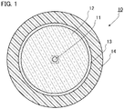
- FIG. 1 is a diagram of the appearance of a cross section perpendicular to the longer direction of an optical fiber according to a first embodiment of the present invention.
- an amplification optical fiber 10 includes a core 11, a cladding 12 that encloses the outer circumferential surface of the core 11 with no gap, an outer cladding 13 that covers the outer circumferential surface of the cladding 12, and a buffer layer 14 that covers the outer cladding 13 as main configurations.
- the diameter of the core 11 is formed greater than the core diameter of a typical single mode fiber, which is 30 ⁇ m, for example.
- the outer diameter of the cladding 12 is 420 ⁇ m, for example, and the outer diameter of the outer cladding 13 is 440 ⁇ m, for example.
- FIGS. 2A to 2E are diagrams of the appearance of the core 11 of the amplification optical fiber 10 and the surrounding portions in FIG. 1 . More specifically, FIG. 2A is the core 11 and the cladding 12 in a region depicted by a dotted line in FIG. 1 , FIG. 2B is a refractive index profile in the region illustrated in FIG. 2A, FIG. 2C is the intensity distributions of a light beam in the LP01 mode and a light beam in the LP02 mode in the case where the light beam in the LP01 mode and the light beam in the LP02 mode are normalized by power when the amplification optical fiber 10 propagates a light beam at a predetermined wavelength, FIG. 2D is the distribution of the magnitude of the Young's modulus in the region illustrated in FIG. 2A, and FIG. 2E is the distribution of the concentration of an active element in the region illustrated in FIG. 2A .
- the refractive index of the cladding 12 is lower than the refractive index of the core 11. It is noted that although not illustrated in the drawing more specifically, the refractive index of the outer cladding 13 is lower than the refractive index of the cladding 12. Moreover, in the amplification optical fiber 10 according to the embodiment, the refractive index of the core 11 is constant in the radial direction, and the refractive index of the cladding 12 is also constant in the radial direction. The relative refractive index difference between the core 11 and the cladding 12 is 0.15%, for example.
- the core 11 and the cladding 12 are formed of silica doped with a necessary dopant as described later, for example.
- the outer cladding 13 is formed of an ultraviolet curing resin or silica doped with a dopant that decreases the refractive index, for example.
- the buffer layer is formed of an ultraviolet curing resin different from one for the outer cladding, for example.
- the amplification optical fiber 10 has the diameter of the core 11 greater than the diameter of a single mode fiber as described above, and is a multimode fiber that propagates a light beam through the core 11 including a light beam in the LP01 mode, which is a fundamental mode, as well as light beams in higher modes in axial symmetry. Therefore, for example, in the case where a light beam including only a light beam in the LP01 mode is entered to the core 11, light beams in higher modes in axial symmetry are sometimes excited. In this case, when a light beam at a predetermined wavelength is entered to the core 11, the modes of light beams propagated through the core 11 include the LP01 mode as well as the LP02 mode, an LP03 mode, and the like.
- the intensity of the light beam in the LP02 mode is generally greater than the intensities of light beams in other higher modes, and has a stronger influence.
- the light beam in the LP02 mode is taken into account in light beams in higher modes, whereas light beams in the LP03 mode and higher modes, which have smaller influence than the influence of the light beam in the LP02 mode, are not taken into account more specifically.
- the light beam in the LP01 mode and the light beam in the LP02 mode are propagated with intensity distributions as illustrated in FIG. 2C in the case where the light beam in the LP01 mode and the light beam in the LP02 mode are normalized by power.
- the wavelengths of the light beams are wavelengths at which an active element is stimulated to emit light in the case where the active element illustrated in FIG. 2E , for example, is pumped.
- the light beams in the modes have intensity distributions that become strongest in the center of the core 11.
- the intensity of the light beam in the LP02 mode is greater than the intensity of the light beam in the LP01 mode. Then, as apart from the center of the core 11 to the radial direction, the intensity of the light beam in the LP01 mode becomes greater than the intensity in the LP02 mode.
- a region in the radial direction from the center of the core 11 in which the intensity of the light beam in the LP01 mode is greater than the intensity of the light beam in the LP02 mode is defined as a first region 11a. Therefore, in the first region 11a, the intensity of the light beam in the LP02 mode is greater than the intensity of the light beam in the LP01 mode.
- the intensity of the light beam in the LP02 mode is again greater than the intensity of the light beam in the LP01 mode. Therefore, a region in which the intensity of the light beam in the LP01 mode is greater than the intensity of the light beam in the LP02 mode in a region on the circumferential side adjacent to the first region 11a is defined as a second region 11b. Then, as further apart from the second region 11b to the radial direction, the light beam is reached on the outer circumferential surface of the core 11. Therefore, on the circumferential side of the second region 11b in the core 11, the intensity of the light beam in the LP02 mode is greater than the intensity of the light beam in the LP01 mode. Therefore, a region on the circumferential side adjacent to the second region 11b in the core 11 is defined as a third region 11c.
- a light beam propagated through the optical fiber is extended and propagated from the core to the region in the cladding adjacent to the core. Therefore, an optical waveguide region is extended to the region in the cladding 12 adjacent to the core 11.
- the optical waveguide region in the cladding 12 in FIG. 2C is defined as a fourth region 12a. In the fourth region 12a, the intensity of the light beam in the LP02 mode is greater than the intensity of the light beam in the LP01 mode.
- a Young's modulus in the third region 11c of the core 11 is smaller than a Young's modulus in the second region 11b.
- a Young's modulus in the fourth region 12a is equal to the Young's modulus in the third region 11c, and smaller than the Young's modulus in the second region 11b.
- a Young's modulus in the first region 11a is equal to the Young's modulus in the second region 11b, and a Young's modulus on the circumferential side of the fourth region 12a of the cladding 12 is greater than the Young's modulus in the fourth region 12a.
- a dopant that decreases a Young's modulus can include germanium (Ge), fluorine (F), boron (B), phosphorus (P), and the like.
- a dopant that increases a Young's modulus can include aluminum (Al).
- germanium, aluminum, and phosphorus are known as dopants that increase a refractive index
- fluorine and boron are known as dopants that decrease a refractive index.
- the following configuration may be fine, for example.
- the first region 11a and the second region 11b are formed of silica doped with germanium at a predetermined concentration
- the third region 11c is formed of silica doped with germanium at a concentration higher than the concentrations in the first region 11a and the second region 11b as well as doped with fluorine, and the loadings of germanium and fluorine are adjusted in such a manner that the refractive index in the third region 11c is equal to the refractive indexes in the first region 11a and the second region 11b.
- dopants other than ones described above may be doped to the first region 11a and the second region 11b as necessary.
- the Young's modulus in the fourth region 12a is equal to the Young's modulus in the third region 11c, and the Young's modulus in the region on the circumferential side of the fourth region 12a of the cladding 12 is greater than the Young's modulus in the fourth region 12a as described above, the following configuration may be fine, for example.
- the region on the circumferential side of the fourth region 12a of the cladding 12 is formed of pure silica doped with no dopant more specifically, the fourth region 12a is formed of silica doped with fluorine and germanium, the refractive index in the fourth region 12a is the refractive index of pure silica, and the loadings of fluorine and germanium are adjusted in such a manner that the Young's modulus in the fourth region 12a is equal to the Young's modulus in the third region 11c.
- dopants other than ones described above may be doped to the fourth region 12a as necessary.
- a dopant that increases a refractive index as well as decreases a Young's modulus and a dopant that decreases a refractive index as well as decreases a Young's modulus are doped together, so that the Young's modulus can be decreased as well as the refractive index can be set in a desired state.
- an active element is doped to the first region 11a and the second region 11b, and any active element is not doped to the third region 11c and the cladding.
- the active element is an element that is pumped by a pumping light beam, typically including ytterbium (Yb).
- active elements like this include a rare earth element such as neodymium (Nd) and erbium (Er) in addition to ytterbium (Yb).
- active elements can include bismuth (Bi) in addition to a rare earth element.
- the concentration of the active element doped to the first region 11a and the second region 11b is 16 ⁇ 10 25 (parts/m 3 ) in the case where the activity limit is imposed by ytterbium, for example.
- the wavelength of the light beam is a predetermined wavelength at which a pumped active element is stimulated to emit light as described above.
- the wavelength is 1,070 nm, for example.
- the light beam in the LP01 mode and the light beam in the LP02 mode have the intensity distributions as illustrated in FIG. 2C , and are propagated through the amplification optical fiber 10.
- the Young's moduli in the third region 11c and the fourth region 12a are smaller than the Young's moduli in the first region 11a and the second region 11b, acoustic waves are gathered in the third region 11c and the fourth region 12a.
- the Young's modulus of the cladding 12 on the circumferential side of the fourth region is greater than the Young's modulus in the fourth region 12a. For this reason, it is suppressed that acoustic waves are spread and transmitted to the regions other than the fourth region 12a of the cladding 12, and such a tendency is observed that acoustic waves are gathered in the fourth region 12a and the third region 11c.
- stimulated Brillouin scattering is caused mainly in the third region 11c and the fourth region 12a.
- light beams propagated through the regions are attenuated due to stimulated Brillouin scattering.
- the intensity of the light beam in the LP02 mode is greater than the intensity of the light beam in the LP01 mode as described above, the loss of the light beam in the LP02 mode caused by stimulated Brillouin scattering is greater than the loss of the light beam in the LP01 mode.
- incident light beams to the core 11 are propagated as the light beam in the LP02 mode is attenuated more than the light beam in the LP01 mode.
- the intensity of the light beam in the LP01 mode is not great so much. Therefore, in the incident light beam to the core 11, the light beam in the LP01 mode is not attenuated so much.
- the incident light beam to the core 11 is amplified as follows.
- the pumping incident light beam to the cladding 12 is mainly propagated through the cladding 12, and the active element doped to the core 11 is pumped when the pumping light beam is passed through the core 11.
- the pumped active element is stimulated to emit light due to a light beam at a predetermined wavelength entered to the core 11 and propagated through the core 11, and the light beam at the predetermined wavelength propagated through the core 11 is amplified by this stimulated emission.
- the active element is doped to the first region 11a and the second region 11b of the core 11, the active element is not doped to the third region 11c in which the intensity of the light beam in the LP02 mode is greater than the intensity of the light beam in the LP01 mode, and the light beam is propagated as described above as the light beam in the LP02 mode is attenuated more than the light beam in the LP01 mode. Therefore, in the case of comparison with an amplification optical fiber in which an active element is uniformly doped to the core, in accordance with the amplification optical fiber 10 according to the embodiment, the light beam in the LP01 mode is more efficiently amplified than the light beam in the LP02 mode and emitted.
- r is a distance from the center of the core 11 in the radial direction
- I 01 (r) is the intensity of the light beam in the LP01 mode illustrated in FIG. 2C on the distance r from the center of the core 11 in the radial direction
- I 02 (r) is the intensity of the light beam in the LP02 mode illustrated in FIG. 2C on the distance r from the center of the core 11 in the radial direction
- n(r) is the doping concentration of the active element on the distance r from the center of the core 11 in the radial direction
- b is the radius of the core 11.
- the unit of r is (m)
- the unit of I 01 (r) and I 02 (r) is (W/m 2 )
- the unit of n(r) is (parts/m 3 )
- the unit of b is (m).
- a light beam is amplified in such a manner that the power of the light beam in the LP01 mode in the light beam to be emitted is greater than the power of the light beam in the LP02 mode, and the beam quality of the light beam to be emitted is further improved.
- the incident light beam to the core 11 can be amplified as the light beam in the LP02 mode is attenuated while suppressing the loss of the light beam in the LP01 mode, so that a light beam of excellent beam quality can be emitted.
- FIG. 3 is a diagram of a fiber laser device according to the embodiment.
- a fiber laser device 1 includes a seed light source 20 that emits a light beam to be a seed light beam, a pumping light source 30 that emits a pumping light beam, an optical combiner 40 that receives the seed light beam and the pumping light beam, and the amplification optical fiber 10 in FIG. 1 that receives the seed light beam and the pumping light beam emitted from the optical combiner 40 as main configurations.
- the seed light source 20 is configured of a semiconductor laser device or a fiber laser device such as a Fabry-Perot laser device and a fiber ring laser device, for example.
- the seed light source 20 is configured to emit a light beam at a predetermined wavelength including the light beam in the LP01 mode from the optical fiber.
- this predetermined wavelength is not limited more specifically.
- the predetermined wavelength is a wavelength at which an active element doped to the amplification optical fiber 10 can be stimulated to emit light.
- the wavelength is 1,070 nm.
- the light beam emitted from the seed light source 20 is emitted from a single mode fiber 25 formed of a core and a cladding that encloses the core.
- the single mode fiber 25 propagates the light beam emitted from the seed light source 20 as a single mode light beam formed of the light beam in the LP01 mode.
- the configuration of the single mode fiber 25 is not limited more specifically. For example, in the case where the wavelength of the seed light beam is 1,070 nm as described above, the core diameter is 10 ⁇ m, and the relative refractive index difference between the core and the cladding is 0.13%.
- the pumping light source 30 is configured of a plurality of laser diodes 31.
- the laser diode 31 is a Fabry-Perot semiconductor laser having a GaAs semiconductor material, for example, and emits a light beam having a center wavelength of 915 nm.
- the laser diodes 31 of the pumping light source 30 are individually connected to multimode fibers 35, and a pumping light beam emitted from the laser diode 31 is propagated through the multimode fiber 35 as a multimode light beam.
- the optical combiner 40 to which the multimode fiber 35 and the single mode fiber 25 are connected is configured in which a portion disposed with the multimode fibers around the single mode fiber 25 is molten and extended for integration.
- the core of the single mode fiber 25 is optically coupled to the core 11 of the amplification optical fiber 10, and the core of the multimode fiber 35 is optically coupled to the cladding 12 of the amplification optical fiber 10.
- a seed light beam emitted from the seed light source 20 is emitted from the single mode fiber 25.
- the wavelength of the seed light beam is 1,070 ⁇ m, for example, as described above.
- the seed light beam including the LP01 mode is propagated.
- the seed light beam propagated through the single mode fiber 25 is entered to the optical combiner 40.
- a pumping light beam that pumps the active element doped to the core 11 of the amplification optical fiber 10 is emitted from the pumping light source 30.
- the wavelength at this time is a wavelength of 915 ⁇ m, for example, as described above. Then, the pumping light beam emitted from the pumping light source 30 is propagated through the multimode fiber 35, and entered to the optical combiner 40.
- the seed light beam entered from the optical combiner 40 to the core 11 of the amplification optical fiber 10 is propagated through the core 11.
- the pumping light beam entered from the optical combiner 40 to the cladding 12 of the amplification optical fiber 10 is mainly propagated through the cladding 12 to pump the active element doped to the core 11.
- the pumped active element is stimulated to emit light caused by the seed light beam, and the seed light beam is amplified.
- the seed light beam sometimes excites a light beam in an axial symmetry mode.
- the light beam in the LP02 mode is mainly attenuated in the third region 11c and the fourth region 12a of the amplification optical fiber 10, and the light beam in the LP02 mode is more attenuated than the light beam in the LP01 mode as a whole. Then, as compared with an amplification optical fiber in which an active element is uniformly doped to the entire core, the light beam in the LP01 mode is more efficiently amplified than the light beam in the LP02 mode, and the light beam in the LP01 mode is emitted. Therefore, a light beam of excellent beam quality that the intensity of the light beam in the LP02 mode is suppressed is emitted from the amplification optical fiber 10.
- the light beam in the LP01 mode can be amplified in the amplification optical fiber 10 while attenuating the light beam in the LP02 mode, so that a light beam of excellent beam quality can be emitted.
- the single mode light beam including the light beam in the LP01 mode is entered as a seed light beam to the amplification optical fiber 10, so that the power of the LP02 mode to be excited can be suppressed to be small, and the LP01 mode can be amplified more greatly. Therefore, a light beam of excellent beam quality can be emitted.
- FIG. 4 is a diagram of another example of the fiber laser device according to the embodiment.
- a fiber laser device 2 includes a pumping light source 30, an amplification optical fiber 10, an optical combiner 40, a double cladding fiber 65 provided between the amplification optical fiber 10 and the optical combiner 40, a first FBG 61 provided on the double cladding fiber 65, a multimode fiber 66 provided on the opposite side of the double cladding fiber 65 of the amplification optical fiber 10, and a second FBG 62 provided on the multimode fiber 66 as main configurations.
- the double cladding fiber 65 has a structure in a cross section perpendicular to the longer direction similar to the structure of the amplification optical fiber 10, including a core, a cladding that encloses the outer circumferential surface of the core with no gap, an outer cladding that encloses the outer circumferential surface of the cladding, and a buffer layer that encloses the outer cladding.
- the outer diameters, the refractive indexes, the Young's moduli, and the like of the core, the cladding, and the outer cladding of the double cladding fiber 65 are similar to the outer diameters, the refractive indexes, the Young's moduli, and the like of the core, the cladding, and the outer cladding of the amplification optical fiber 10.
- the double cladding fiber 65 is different from the amplification optical fiber 10 in that no active element is doped to the core of the double cladding fiber 65.
- the core and cladding of the double cladding fiber 65 have Young's moduli similar to the Young's moduli of the core and cladding of the amplification optical fiber 10, when a light beam including the light beam in the LP01 mode and the light beam in the LP02 mode is propagated through the core of the double cladding fiber 65, the light beam in the LP02 mode is more attenuated than the light beam in the LP01 mode similarly to the description of the amplification optical fiber 10.
- an active element is not necessarily doped to the core, and the double cladding fiber 65, as well as the amplification optical fiber 10, is the optical fiber according to the present invention.
- One end of the double cladding fiber 65 is connected to the optical combiner 40 similarly to the fiber laser device 1 in which the amplification optical fiber 10 is connected to the optical combiner 40, and the core of the multimode fiber 35 is optically connected to the cladding of the double cladding fiber 65.
- the other end of the double cladding fiber 65 is connected to one end of the amplification optical fiber 10
- the core of the double cladding fiber 65 is connected to the core 11 of the amplification optical fiber 10
- the cladding of the double cladding fiber 65 is connected to the cladding 12 of the amplification optical fiber 10.
- the first FBG 61 is provided on the core of the double cladding fiber 65. In this manner, the first FBG 61 is provided on one side of the amplification optical fiber 10. In the first FBG 61, a portion in which the refractive index is high is repeated along the longer direction of the double cladding fiber 65 in constant cycles.
- the first FBG 61 is configured in which at least a part of wavelengths of a light beam emitted from the pumped active element of the amplification optical fiber 10 is reflected by adjusting the cycle. In the case where an active element is ytterbium as described above, the reflectance of the first FBG 61 is 100%, for example, at a wavelength of 1,070 nm, for example.
- the multimode fiber 66 provided on the opposite side of the double cladding fiber 65 of the amplification optical fiber 10 includes a core and a cladding that encloses the outer circumferential surface of the core with no gap.
- the outer diameters, the refractive indexes, the Young's moduli, and the like of the core and cladding of the multimode fiber 66 are similar to the outer diameters, the refractive indexes, the Young's moduli, and the like of the core and cladding of the amplification optical fiber 10.
- no active element is doped to the core of the multimode fiber 66.
- the multimode fiber 66 is different from the amplification optical fiber 10 in that no active element is doped to the core and the outer cladding is not included.
- the core and cladding of the multimode fiber 66 have Young's moduli similar to the Young's moduli of the core and cladding of the amplification optical fiber 10, when a light beam including the light beam in the LP01 mode and the light beam in the LP02 mode is propagated through the core of the multimode fiber 66, the light beam in the LP02 mode is more attenuated than the light beam in the LP01 mode, similarly to the description of the amplification optical fiber 10.
- the multimode fiber 66, as well as the amplification optical fiber 10 and the double cladding fiber 65 is the optical fiber according to the present invention.
- One end of the multimode fiber 66 is connected to the other end of the amplification optical fiber 10, and the core 11 of the amplification optical fiber 10 is connected to the core of the multimode fiber 66. Moreover, in the embodiment, the other end of the multimode fiber 66 is a free end as nothing is connected.
- the second FBG 62 is provided on the core of the multimode fiber 66. In this manner, the second FBG 62 is provided on the other side of the amplification optical fiber 10. In the second FBG 62, a portion in which the refractive index is high is repeated along the longer direction of the multimode fiber 66 in constant cycles.
- the second FBG 62 is configured in which a light beam at a wavelength the same as the wavelength of the light beam reflected off the first FBG 61 is reflected at a reflectance lower than the reflectance of the first FBG 61.
- the second FBG 62 is configured in which a light beam at a wavelength the same as the wavelength of the light beam reflected off the first FBG 61 is reflected at a reflectance of 50%.
- the pumping light beam is entered to the cladding of the double cladding fiber 65 in the optical combiner 40, and entered from the cladding of the double cladding fiber 65 to the cladding of the amplification optical fiber 10.
- the active element doped to the core 11 of the amplification optical fiber 10 is pumped.
- the pumped active element emits a light beam of spontaneous emission at a specific wavelength.
- the light beam of spontaneous emission at this time is a light beam including a wavelength of 1,070 nm, for example, and having a certain wavelength range.
- the light beam of spontaneous emission is propagated through the core 11 of the amplification optical fiber 10, reflected off the first FBG 61 provided on the core of the double cladding fiber 65.
- the reflected light beam is reflected off the second FBG 62 and resonates, and the resonating light beam is amplified when propagated through the core 11 of the amplification optical fiber 10.
- the amplification optical fiber 10 similarly to the fiber laser device 1, the light beam in the LP02 mode is attenuated while suppressing the loss of the light beam in the LP01 mode propagated through the core 11.
- the light beam in the LP01 mode is more efficiently amplified than the light beam in the LP02 mode.
- the light beam in the LP02 mode is attenuated while suppressing the loss of the light beam in the LP01 mode propagated through the core 11.
- the light beam in the LP02 mode is attenuated, and the resonating light beam is amplified.
- a part of the light beam is transmitted through the second FBG, and emitted from the multimode fiber 66.
- the light beam in the LP02 mode is attenuated as the light beam is propagated through the multimode fiber 66.
- the light beam in the LP02 mode is more attenuated than the light beam in the LP01 mode when the light beam is propagated through the core 11 of the amplification optical fiber 10 and when the light beam is propagated through the core of the double cladding fiber 65 and the core of the multimode fiber 66, so that a light beam of excellent beam quality can be emitted.
- a wavelength conversion element 50 that converts the wavelength of the light beam to be emitted is disposed on the path of a light beam emitted from the fiber laser devices 1 and 2.
- the wavelength conversion element 50 is an element that converts the wavelength of an incident light beam into the long wavelength side and emits a light beam whose wavelength is converted. In the case where a near infrared light beam having a wavelength of 1,070 nm, for example, is entered, the element converts the wavelength of the light beam, and emits a visible light beam at a wavelength of 535 nm.
- the wavelength conversion element 50 can include an optical fiber that causes stimulated Raman scattering.
- the optical fiber that causes stimulated Raman scattering can include an optical fiber including a core doped with a dopant that increases a nonlinear optical constant.
- the dopant includes germanium and phosphorus.
- the wavelength conversion element 50 generally converts the wavelength in the case where a light beam of a predetermined intensity or greater is entered.
- the intensity threshold of the incident light beam whose wavelength is converted can be changed depending on the diameter of the core, the doping concentration of the dopant, the length, and the like.
- the wavelength conversion element 50 can include a wavelength conversion element formed of a single crystal of lithium niobate and lithium tantalate.
- the wavelength conversion element 50 In the case where the wavelength conversion element 50 is disposed, light beams emitted from the amplification optical fiber 10 and the multimode fiber 66 are condensed at a lens not illustrated, and entered to the wavelength conversion element 50. At this time, a light beam of excellent beam quality is emitted from the amplification optical fiber 10 and the multimode fiber 66 as described above, so that the condensing characteristics of an incident light beam to the wavelength conversion element 50 can be improved. The condensing characteristics of the light beam are improved as described above, so that the power density of a light beam is increased, and the conversion efficiency of the wavelength conversion element 50 is improved.
- the present invention is described as the embodiment is taken as an example. However, the present invention is not limited thereto.
- the Young's modulus is smaller in the entire region of the third region 11c than the Young's modulus in the second region 11b.
- the present invention is not limited thereto. It may be fine that a part of the Young's modulus in the third region 11c is smaller than the Young's modulus in the second region 11b.
- the optical fiber according to the present invention includes the amplification optical fiber 10, the double cladding fiber 65, and the multimode fiber 66 as examples. However, the present invention is not limited thereto.
- the optical fiber is an optical fiber that propagates a light beam at a predetermined wavelength at least in the LP01 mode and the LP02 mode, and can be appropriately modified as long as at least a part of the Young's modulus in the third region 11c is smaller than the Young's modulus in the second region 11b. Therefore, it may be fine that light beams other than light beams in the LP01 mode and the LP02 mode are propagated through the optical fiber according to the present invention.
- FIG. 5 is a diagram of an exemplary distribution of the magnitude of the Young's modulus in the case where the Young's modulus in the third region 11c and the Young's modulus in the fourth region 12a of the amplification optical fiber 10 are different from each other, which is a diagram corresponding to FIG. 2D . As illustrated in FIG.
- the Young's modulus in the third region 11c is smaller than the Young's modulus in the fourth region 12a
- the Young's modulus in the fourth region 12a is smaller than the Young's moduli in the first region 11a and the second region 11b. It is noted that it may be fine that the distributions of the magnitude of the Young's moduli of the double cladding fiber 65 and the multimode fiber 66 are this distribution. In order to provide this distribution of the magnitude of the Young's modulus, it is fine that a dopant that increases a Young's modulus is doped to the fourth region 12a, for example.
- the Young's modulus in the third region 11c is smaller than the Young's modulus in the fourth region 12a, so that acoustic waves can be gathered more in the third region 11c than in the fourth region 12a.
- the difference between the intensity of the light beam in the LP02 mode and the intensity of the light beam in the LP01 mode is greater in the third region 11c than in the fourth region 12a.
- acoustic waves are gathered more in the third region 11c than in the fourth region 12a to increase the influence of stimulated Brillouin scattering more in the third region 11c than in the fourth region 12a, so that the loss of the light beam in the LP02 mode can be more increased than the loss of the light beam in the LP01 mode. Accordingly, it is possible to further improve beam quality.
- FIG. 6 is a diagram of another example of the distribution of the magnitude of the Young's modulus in the case where the Young's modulus in the third region 11c and the Young's modulus in the fourth region 12a of the amplification optical fiber 10 are different from each other, which is a diagram corresponding to FIG. 2D .
- the Young's modulus in the fourth region 12a is smaller than the Young's modulus in the third region 11c. It is noted that it may be fine that the distributions of the magnitude of the Young's moduli of the double cladding fiber 65 and the multimode fiber 66 are this distribution.
- a dopant that decreases a Young's modulus may be doped to the fourth region 12a more than in the case where the Young's modulus in the third region 11c is the same as the Young's modulus in the fourth region 12a, for example.
- Acoustic waves can be gathered in the third region 11c because the Young's modulus is smaller than the Young's modulus in the second region 11b.
- the Young's modulus in the fourth region 12a is smaller than the Young's modulus in the third region 11c as described above, so that acoustic waves can be further apart from the second region 11b, and the influence of stimulated Brillouin scattering can be decreased in the second region 11b.
- the Young's modulus on the circumferential side of the fourth region 12a of the cladding is the same as the Young's modulus in the fourth region 12a, or the Young's modulus in the fourth region 12a is the same as the Young's modulus on the circumferential side of the fourth region of the cladding.
- the Young's modulus on the circumferential side of the fourth region 12a of the cladding is preferably greater than the Young's modulus in the fourth region 12a as in the embodiment.
- the double cladding fiber 65, and the multimode fiber 66 it may be fine that the Young's modulus in the first region 11a and the Young's modulus in the second region 11b are different from each other.
- FIG. 7 is a diagram of the distribution of the concentration of an active element in the case where the active element is doped to the third region 11c in the amplification optical fiber 10. As illustrated in FIG. 7 , it may be fine that an active element is doped to the third region 11c. In this case, the concentration of the active element doped to the third region 11c is preferably smaller than the concentration of the active element doped to at least the second region 11b, and Expression (1) described above is more preferably satisfied.
- the concentration of the active element Yb to be doped is 16 ⁇ 10 25 (parts/m 3 ) in the first region 11a and the second region 11b, and is 8 ⁇ 10 25 (parts/m 3 ) in the third region 11c.
- the refractive index of the core 11 is constant in the radial direction.
- the present invention is not limited thereto. It may be fine that at least one of the first region 11a, the second region 11b, and the third region 11c has a refractive index different from that in the other regions. For example, it may be fine that the refractive index in the third region 11c is higher than the refractive indexes in the first region 11a and the second region 11b.
- the first region 11a and the second region 11b are formed of silica doped with germanium at a predetermined concentration and the third region 11c is formed of silica doped with germanium at a concentration higher than the concentrations in the first region 11a and the second region 11b.
- the refractive index in the third region 11c is made the same as the refractive index of the first region 11a or the second region 11b, the optical fiber is easily manufactured.
- the refractive index in the third region 11c is lower than the refractive indexes in the first region 11a and the second region 11b and higher than the refractive index of the cladding 12 in order that the third region 11c functions as a part of the core 11.
- the refractive index of the cladding 12 is constant in the radial direction.
- the refractive index in the region on the circumferential side of the fourth region 12a is different from the refractive index in the fourth region 12a.
- a dopant that decreases a Young's modulus and a refractive index is doped to the fourth region 12a, so that the refractive index in the fourth region 12a can be decreased more than the refractive index on the circumferential side of the fourth region.
- a dopant that decreases a Young's modulus and a refractive index and a dopant that deceases a Young's modulus and increases a refractive index are together doped to the fourth region 12a and the refractive index in the fourth region 12a is increased more than the refractive index in the region on the circumferential side of the fourth region 12a in a range in which the fourth region 12a functions as the cladding.
- the amplification optical fiber 10 according to the embodiment described above has the structure in which only the core 11 is disposed in the cladding 12.
- the present invention is not limited thereto.
- FIG. 8 is a diagram of an exemplary modification of the amplification optical fiber 10 in this configuration. It is noted that components the same as or equivalent to the components of the embodiment are designated the same reference numerals and signs, and the overlapping description will be omitted unless otherwise specified.
- an amplification optical fiber 15 is different from the amplification optical fiber 10 according to the first embodiment in that a pair of stress application parts 18 sandwiching a core 11 is provided in a cladding 12.
- the amplification optical fiber 15 according to the exemplary modification is a polarization maintaining fiber (a PANDA fiber).
- a PANDA fiber polarization maintaining fiber
- the stress application parts 18 have a diameter of 35 ⁇ m, for example, and a relative refractive index difference of -1% to the cladding 12, and are spaced from the outer circumferential surface of the core 11 with a gap of 5 ⁇ m.
- a material forming the stress application part 18 can include silica doped with boron (B), for example, as a dopant. These stress application parts 18 are provided, so that a light beam of single polarization can be propagated.
- This amplification optical fiber 15 can provide a polarization extinction ratio of about 20 dB between an incident light beam to the core 11 and a light beam emitted from the core 11.
- the light beam of single polarization is emitted, so that wavelengths can be efficiently converted with a light beam emitted as compared with the case where a light beam of no single polarization is emitted.
- wavelengths can be efficiently converted in the wavelength conversion element 50 in the case where the amplification optical fiber 15 is used instead of the amplification optical fiber 10.
- the amplification optical fiber 15 is used instead of the amplification optical fiber 10, and similar stress application parts are disposed on the claddings of the double cladding fiber 65 and the multimode fiber 66, so that a light beam whose wavelength is converted can be efficiently obtained in the wavelength conversion element 50.
- an optical fiber that can emit a light beam of excellent beam quality even in the case where the core diameter is great and a fiber laser device using the same are provided, and are expected to be used in a processing fiber laser device and the like.
Landscapes
- Physics & Mathematics (AREA)
- Electromagnetism (AREA)
- Optics & Photonics (AREA)
- Engineering & Computer Science (AREA)
- Plasma & Fusion (AREA)
- General Physics & Mathematics (AREA)
- Lasers (AREA)
- Optical Fibers, Optical Fiber Cores, And Optical Fiber Bundles (AREA)
Claims (15)
- Fibre optique (10) comprenant :une âme (11) ayant une première région (11c) et une seconde région (11b), etune gaine (12) qui renferme l'âme (11), la fibre optique étant configurée pour propager un faisceau lumineux à une longueur d'onde prédéterminée au moins dans un mode LP01 et un mode LP02,dans laquelle ladite première région (11c) ayant une intensité du faisceau lumineux dans le mode LP02 supérieure à une intensité du faisceau lumineux dans le mode LP01 et étant située sur un côté circonférentiel de la seconde région (11b),ladite seconde région (11b) ayant l'intensité du faisceau lumineux dans le mode LP01 supérieure à l'intensité du faisceau lumineux dans le mode LP02,dans laquelle au moins une partie d'un module de Young dans la première région (11c) est inférieure à un module de Young dans la seconde région (11b).
- Fibre optique (10) selon la revendication 1, dans laquelle un module de Young dans une première région (11c) complète est inférieur à un module de Young dans la seconde région (11b).
- Fibre optique (10) selon la revendication 1 ou 2, dans laquelle un indice de réfraction de l'âme (11) est constant dans un sens radial.
- Fibre optique (10) selon l'une quelconque des revendications 1 à 3, dans laquelle au moins une partie d'un module de Young dans une région de guide d'onde dans la gaine (12) à travers laquelle le faisceau lumineux à la longueur d'onde prédéterminée est propagé est inférieure à un module de Young dans la seconde région (11b).
- Fibre optique (10) selon la revendication 4, dans laquelle un module de Young dans l'intégralité de la région du guide d'onde dans la gaine (12) est inférieur à un module de Young dans la seconde région (11b).
- Fibre optique (10) selon la revendication 5, dans laquelle au moins une partie d'un module de Young dans la première région (11c) est inférieure au module de Young dans la région de guide d'onde dans la gaine (12).
- Fibre optique (10) selon l'une quelconque des revendications 4 à 6, dans laquelle un indice de réfraction de la gaine (12) est constant dans un sens radial.
- Fibre optique (10) selon l'une quelconque des revendications 1 à 7, dans laquelle, dans la première région (11c), un dopant qui augmente un indice de réfraction et réduit un module de Young et un dopant qui réduit un indice de réfraction et réduit un module de Young sont dopés ensemble.
- Fibre optique (10) selon l'une quelconque des revendications 1 à 8, dans laquelle au moins une partie de l'âme (11) est dopée avec un élément actif qui est stimulé pour émettre le faisceau lumineux à la longueur d'onde prédéterminée.
- Fibre optique (10) selon la revendication 9, dans laquelle au moins une partie de la seconde région (11b) est dopée avec l'élément actif à une concentration supérieure à celle dans la première région (11c).
- Fibre optique (10) selon la revendication 10, dans laquelle la première région (11c) n'est pas dopée avec un élément actif.
- Fibre optique (10) selon l'une quelconque des revendications 8 à 11, dans laquelle une paire de parties d'application de contrainte prenant l'âme (11) en sandwich est prévue dans la gaine (12).
- Dispositif laser à fibre (1) comprenant :la fibre optique (10) selon l'une quelconque des revendications 8 à 12 ;une source lumineuse de germe (20) configurée pour émettre un faisceau lumineux de germe à la longueur d'onde prédéterminée à entrer dans l'âme (11) ; etune source lumineuse de pompage (30) configurée pour émettre un faisceau lumineux de pompage qui pompe l'élément actif.
- Dispositif laser à fibre (1) selon la revendication 13, dans lequel le faisceau lumineux de germe excite uniquement un mode de symétrie axiale dans le faisceau optique (10).
- Dispositif laser à fibre (2) comprenant :la fibre optique (10) selon l'une quelconque des revendications 8 à 12 ;une source lumineuse de pompage (30) configurée pour émettre un faisceau lumineux de pompage qui pompe l'élément actif ;un premier réseau de Bragg sur fibre, FBG, (61) prévu sur un côté de la fibre optique (10) et configuré pour réfléchir le faisceau lumineux à la longueur d'onde prédéterminée dans un faisceau lumineux émis depuis l'élément actif pompé par le faisceau lumineux de pompage ; etun second FBG (62) prévu sur l'autre côté de la fibre optique (10) et configuré pour réfléchir un faisceau lumineux à une longueur d'onde identique à une longueur d'onde du faisceau lumineux réfléchi du premier FBG (61) à un facteur de réflexion inférieur à celui du premier FBG (61).
Applications Claiming Priority (2)
| Application Number | Priority Date | Filing Date | Title |
|---|---|---|---|
| JP2012220588A JP5694266B2 (ja) | 2012-10-02 | 2012-10-02 | 光ファイバ及びそれを用いたファイバレーザ装置 |
| PCT/JP2013/075826 WO2014054480A1 (fr) | 2012-10-02 | 2013-09-25 | Fibre optique et dispositif laser à fibre l'utilisant |
Publications (3)
| Publication Number | Publication Date |
|---|---|
| EP2905638A1 EP2905638A1 (fr) | 2015-08-12 |
| EP2905638A4 EP2905638A4 (fr) | 2016-06-08 |
| EP2905638B1 true EP2905638B1 (fr) | 2020-04-29 |
Family
ID=50434808
Family Applications (1)
| Application Number | Title | Priority Date | Filing Date |
|---|---|---|---|
| EP13844427.8A Active EP2905638B1 (fr) | 2012-10-02 | 2013-09-25 | Fibre optique et dispositif laser à fibre l'utilisant |
Country Status (6)
| Country | Link |
|---|---|
| US (1) | US9529148B2 (fr) |
| EP (1) | EP2905638B1 (fr) |
| JP (1) | JP5694266B2 (fr) |
| CN (1) | CN104737048B (fr) |
| DK (1) | DK2905638T3 (fr) |
| WO (1) | WO2014054480A1 (fr) |
Families Citing this family (7)
| Publication number | Priority date | Publication date | Assignee | Title |
|---|---|---|---|---|
| JP5771586B2 (ja) * | 2012-10-16 | 2015-09-02 | 株式会社フジクラ | 光ファイバ及びそれを用いたファイバレーザ装置 |
| JP6744074B2 (ja) * | 2015-07-16 | 2020-08-19 | 株式会社フジクラ | 光ファイバグレーティング用光ファイバおよびファイバレーザ装置 |
| WO2017136831A1 (fr) * | 2016-02-05 | 2017-08-10 | Nufern | Fibres optiques à mélange de modes et procédés et systèmes utilisant celles-ci |
| KR102472018B1 (ko) * | 2017-05-15 | 2022-11-28 | 아이피지 포토닉스 코포레이션 | 고전력 클래딩 펌핑되는 단일 모드 섬유 라만 레이저 |
| EP3734336A4 (fr) * | 2017-12-28 | 2021-08-25 | Fujikura, Ltd. | Fibre optique et dispositif laser |
| KR102658385B1 (ko) * | 2018-06-29 | 2024-04-16 | 아이피지 포토닉스 코포레이션 | 고출력 레이저용 능동 도파로 |
| CN113498567A (zh) * | 2019-03-29 | 2021-10-12 | 株式会社藤仓 | 活性元素添加光纤、谐振器、以及光纤激光装置 |
Family Cites Families (12)
| Publication number | Priority date | Publication date | Assignee | Title |
|---|---|---|---|---|
| FR2683053B1 (fr) * | 1991-10-29 | 1994-10-07 | Thomson Csf | Fibre optique et procede de fabrication. |
| JPH10160947A (ja) * | 1996-11-29 | 1998-06-19 | Toray Ind Inc | 広帯域プラスチッククラッド光ファイバ |
| US5818630A (en) | 1997-06-25 | 1998-10-06 | Imra America, Inc. | Single-mode amplifiers and compressors based on multi-mode fibers |
| US7130514B1 (en) * | 2005-06-15 | 2006-10-31 | Corning Incorporated | High SBS threshold optical fiber |
| EP1891472B1 (fr) | 2005-06-15 | 2019-09-11 | Corning Incorporated | Fibre optique a seuil eleve de diffusion brillouin stimulee, avec dopant a l'aluminium |
| JP2007333795A (ja) * | 2006-06-12 | 2007-12-27 | Furukawa Electric Co Ltd:The | 光ファイバ心線及びその製造方法 |
| JP5144355B2 (ja) * | 2007-04-24 | 2013-02-13 | 古河電気工業株式会社 | 光ファイバグレーティングデバイスおよび光ファイバレーザ |
| WO2010146792A1 (fr) * | 2009-06-17 | 2010-12-23 | 株式会社フジクラ | Fibre optique à gainages multiples, module de fibre optique, laser à fibre optique et amplificateur à fibre optique |
| US8285101B2 (en) * | 2009-10-15 | 2012-10-09 | Ipg Photonics Corporation | Optical fiber apparatus with suppression of higher order modes |
| US8498044B2 (en) * | 2009-12-22 | 2013-07-30 | Fujikura Ltd. | Amplification optical fiber, and optical fiber amplifier and resonator using the same |
| JP2012088356A (ja) * | 2010-10-15 | 2012-05-10 | Sumitomo Electric Ind Ltd | 光ファイバ心線及びそれを備えた光電気複合ケーブル |
| JP4667535B1 (ja) * | 2010-11-02 | 2011-04-13 | 株式会社フジクラ | 増幅用光ファイバ、及び、それを用いた光ファイバ増幅器及び共振器 |
-
2012
- 2012-10-02 JP JP2012220588A patent/JP5694266B2/ja active Active
-
2013
- 2013-09-25 DK DK13844427.8T patent/DK2905638T3/da active
- 2013-09-25 US US14/432,347 patent/US9529148B2/en active Active
- 2013-09-25 WO PCT/JP2013/075826 patent/WO2014054480A1/fr not_active Ceased
- 2013-09-25 CN CN201380051289.3A patent/CN104737048B/zh active Active
- 2013-09-25 EP EP13844427.8A patent/EP2905638B1/fr active Active
Non-Patent Citations (1)
| Title |
|---|
| None * |
Also Published As
| Publication number | Publication date |
|---|---|
| US9529148B2 (en) | 2016-12-27 |
| DK2905638T3 (da) | 2020-07-20 |
| JP5694266B2 (ja) | 2015-04-01 |
| CN104737048B (zh) | 2019-01-01 |
| US20150253497A1 (en) | 2015-09-10 |
| EP2905638A1 (fr) | 2015-08-12 |
| CN104737048A (zh) | 2015-06-24 |
| WO2014054480A1 (fr) | 2014-04-10 |
| EP2905638A4 (fr) | 2016-06-08 |
| JP2014074741A (ja) | 2014-04-24 |
Similar Documents
| Publication | Publication Date | Title |
|---|---|---|
| EP2910987B1 (fr) | Fibre optique et appareil à fibre optique la comprenant | |
| JP5779606B2 (ja) | 増幅用光ファイバ、及び、それを用いたファイバレーザ装置 | |
| US8498044B2 (en) | Amplification optical fiber, and optical fiber amplifier and resonator using the same | |
| EP2905638B1 (fr) | Fibre optique et dispositif laser à fibre l'utilisant | |
| EP2642620B1 (fr) | Fibre optique d'amplification, et amplificateur à fibre optique et oscillateur mettant en uvre ladite fibre | |
| EP2696451B1 (fr) | Fibre optique d'amplification, et amplificateur à fibres optiques et résonateur l'utilisant | |
| EP3462553B1 (fr) | Fibre optique et dispositif laser | |
| US9543733B2 (en) | Photonic bandgap fiber and fiber laser device using same | |
| EP3196991B1 (fr) | Dispositif de laser à fibre | |
| EP2919334B1 (fr) | Fibre optique amplificatrice et amplificateur optique | |
| EP3734337A1 (fr) | Fibre optique et dispositif laser | |
| EP3547468B1 (fr) | Fibre optique d'amplification, dispositif laser à fibre et résonateur optique |
Legal Events
| Date | Code | Title | Description |
|---|---|---|---|
| PUAI | Public reference made under article 153(3) epc to a published international application that has entered the european phase |
Free format text: ORIGINAL CODE: 0009012 |
|
| 17P | Request for examination filed |
Effective date: 20150429 |
|
| AK | Designated contracting states |
Kind code of ref document: A1 Designated state(s): AL AT BE BG CH CY CZ DE DK EE ES FI FR GB GR HR HU IE IS IT LI LT LU LV MC MK MT NL NO PL PT RO RS SE SI SK SM TR |
|
| AX | Request for extension of the european patent |
Extension state: BA ME |
|
| DAX | Request for extension of the european patent (deleted) | ||
| RA4 | Supplementary search report drawn up and despatched (corrected) |
Effective date: 20160511 |
|
| RIC1 | Information provided on ipc code assigned before grant |
Ipc: G02B 6/036 20060101AFI20160503BHEP Ipc: H01S 3/067 20060101ALI20160503BHEP Ipc: G02B 6/024 20060101ALI20160503BHEP |
|
| GRAP | Despatch of communication of intention to grant a patent |
Free format text: ORIGINAL CODE: EPIDOSNIGR1 |
|
| STAA | Information on the status of an ep patent application or granted ep patent |
Free format text: STATUS: GRANT OF PATENT IS INTENDED |
|
| INTG | Intention to grant announced |
Effective date: 20191212 |
|
| GRAS | Grant fee paid |
Free format text: ORIGINAL CODE: EPIDOSNIGR3 |
|
| GRAA | (expected) grant |
Free format text: ORIGINAL CODE: 0009210 |
|
| STAA | Information on the status of an ep patent application or granted ep patent |
Free format text: STATUS: THE PATENT HAS BEEN GRANTED |
|
| AK | Designated contracting states |
Kind code of ref document: B1 Designated state(s): AL AT BE BG CH CY CZ DE DK EE ES FI FR GB GR HR HU IE IS IT LI LT LU LV MC MK MT NL NO PL PT RO RS SE SI SK SM TR |
|
| REG | Reference to a national code |
Ref country code: GB Ref legal event code: FG4D |
|
| REG | Reference to a national code |
Ref country code: CH Ref legal event code: EP |
|
| REG | Reference to a national code |
Ref country code: DE Ref legal event code: R096 Ref document number: 602013068545 Country of ref document: DE |
|
| REG | Reference to a national code |
Ref country code: AT Ref legal event code: REF Ref document number: 1264164 Country of ref document: AT Kind code of ref document: T Effective date: 20200515 |
|
| REG | Reference to a national code |
Ref country code: IE Ref legal event code: FG4D |
|
| REG | Reference to a national code |
Ref country code: DK Ref legal event code: T3 Effective date: 20200716 |
|
| REG | Reference to a national code |
Ref country code: NL Ref legal event code: MP Effective date: 20200429 |
|
| REG | Reference to a national code |
Ref country code: LT Ref legal event code: MG4D |
|
| PG25 | Lapsed in a contracting state [announced via postgrant information from national office to epo] |
Ref country code: GR Free format text: LAPSE BECAUSE OF FAILURE TO SUBMIT A TRANSLATION OF THE DESCRIPTION OR TO PAY THE FEE WITHIN THE PRESCRIBED TIME-LIMIT Effective date: 20200730 Ref country code: SE Free format text: LAPSE BECAUSE OF FAILURE TO SUBMIT A TRANSLATION OF THE DESCRIPTION OR TO PAY THE FEE WITHIN THE PRESCRIBED TIME-LIMIT Effective date: 20200429 Ref country code: PT Free format text: LAPSE BECAUSE OF FAILURE TO SUBMIT A TRANSLATION OF THE DESCRIPTION OR TO PAY THE FEE WITHIN THE PRESCRIBED TIME-LIMIT Effective date: 20200831 Ref country code: IS Free format text: LAPSE BECAUSE OF FAILURE TO SUBMIT A TRANSLATION OF THE DESCRIPTION OR TO PAY THE FEE WITHIN THE PRESCRIBED TIME-LIMIT Effective date: 20200829 Ref country code: LT Free format text: LAPSE BECAUSE OF FAILURE TO SUBMIT A TRANSLATION OF THE DESCRIPTION OR TO PAY THE FEE WITHIN THE PRESCRIBED TIME-LIMIT Effective date: 20200429 Ref country code: FI Free format text: LAPSE BECAUSE OF FAILURE TO SUBMIT A TRANSLATION OF THE DESCRIPTION OR TO PAY THE FEE WITHIN THE PRESCRIBED TIME-LIMIT Effective date: 20200429 Ref country code: NO Free format text: LAPSE BECAUSE OF FAILURE TO SUBMIT A TRANSLATION OF THE DESCRIPTION OR TO PAY THE FEE WITHIN THE PRESCRIBED TIME-LIMIT Effective date: 20200729 |
|
| REG | Reference to a national code |
Ref country code: AT Ref legal event code: MK05 Ref document number: 1264164 Country of ref document: AT Kind code of ref document: T Effective date: 20200429 |
|
| PG25 | Lapsed in a contracting state [announced via postgrant information from national office to epo] |
Ref country code: BG Free format text: LAPSE BECAUSE OF FAILURE TO SUBMIT A TRANSLATION OF THE DESCRIPTION OR TO PAY THE FEE WITHIN THE PRESCRIBED TIME-LIMIT Effective date: 20200729 Ref country code: HR Free format text: LAPSE BECAUSE OF FAILURE TO SUBMIT A TRANSLATION OF THE DESCRIPTION OR TO PAY THE FEE WITHIN THE PRESCRIBED TIME-LIMIT Effective date: 20200429 Ref country code: LV Free format text: LAPSE BECAUSE OF FAILURE TO SUBMIT A TRANSLATION OF THE DESCRIPTION OR TO PAY THE FEE WITHIN THE PRESCRIBED TIME-LIMIT Effective date: 20200429 Ref country code: RS Free format text: LAPSE BECAUSE OF FAILURE TO SUBMIT A TRANSLATION OF THE DESCRIPTION OR TO PAY THE FEE WITHIN THE PRESCRIBED TIME-LIMIT Effective date: 20200429 |
|
| PG25 | Lapsed in a contracting state [announced via postgrant information from national office to epo] |
Ref country code: AL Free format text: LAPSE BECAUSE OF FAILURE TO SUBMIT A TRANSLATION OF THE DESCRIPTION OR TO PAY THE FEE WITHIN THE PRESCRIBED TIME-LIMIT Effective date: 20200429 Ref country code: NL Free format text: LAPSE BECAUSE OF FAILURE TO SUBMIT A TRANSLATION OF THE DESCRIPTION OR TO PAY THE FEE WITHIN THE PRESCRIBED TIME-LIMIT Effective date: 20200429 |
|
| PG25 | Lapsed in a contracting state [announced via postgrant information from national office to epo] |
Ref country code: AT Free format text: LAPSE BECAUSE OF FAILURE TO SUBMIT A TRANSLATION OF THE DESCRIPTION OR TO PAY THE FEE WITHIN THE PRESCRIBED TIME-LIMIT Effective date: 20200429 Ref country code: SM Free format text: LAPSE BECAUSE OF FAILURE TO SUBMIT A TRANSLATION OF THE DESCRIPTION OR TO PAY THE FEE WITHIN THE PRESCRIBED TIME-LIMIT Effective date: 20200429 Ref country code: EE Free format text: LAPSE BECAUSE OF FAILURE TO SUBMIT A TRANSLATION OF THE DESCRIPTION OR TO PAY THE FEE WITHIN THE PRESCRIBED TIME-LIMIT Effective date: 20200429 Ref country code: RO Free format text: LAPSE BECAUSE OF FAILURE TO SUBMIT A TRANSLATION OF THE DESCRIPTION OR TO PAY THE FEE WITHIN THE PRESCRIBED TIME-LIMIT Effective date: 20200429 Ref country code: IT Free format text: LAPSE BECAUSE OF FAILURE TO SUBMIT A TRANSLATION OF THE DESCRIPTION OR TO PAY THE FEE WITHIN THE PRESCRIBED TIME-LIMIT Effective date: 20200429 Ref country code: CZ Free format text: LAPSE BECAUSE OF FAILURE TO SUBMIT A TRANSLATION OF THE DESCRIPTION OR TO PAY THE FEE WITHIN THE PRESCRIBED TIME-LIMIT Effective date: 20200429 Ref country code: ES Free format text: LAPSE BECAUSE OF FAILURE TO SUBMIT A TRANSLATION OF THE DESCRIPTION OR TO PAY THE FEE WITHIN THE PRESCRIBED TIME-LIMIT Effective date: 20200429 |
|
| REG | Reference to a national code |
Ref country code: DE Ref legal event code: R097 Ref document number: 602013068545 Country of ref document: DE |
|
| PG25 | Lapsed in a contracting state [announced via postgrant information from national office to epo] |
Ref country code: SK Free format text: LAPSE BECAUSE OF FAILURE TO SUBMIT A TRANSLATION OF THE DESCRIPTION OR TO PAY THE FEE WITHIN THE PRESCRIBED TIME-LIMIT Effective date: 20200429 Ref country code: PL Free format text: LAPSE BECAUSE OF FAILURE TO SUBMIT A TRANSLATION OF THE DESCRIPTION OR TO PAY THE FEE WITHIN THE PRESCRIBED TIME-LIMIT Effective date: 20200429 |
|
| PLBE | No opposition filed within time limit |
Free format text: ORIGINAL CODE: 0009261 |
|
| STAA | Information on the status of an ep patent application or granted ep patent |
Free format text: STATUS: NO OPPOSITION FILED WITHIN TIME LIMIT |
|
| 26N | No opposition filed |
Effective date: 20210201 |
|
| PG25 | Lapsed in a contracting state [announced via postgrant information from national office to epo] |
Ref country code: MC Free format text: LAPSE BECAUSE OF FAILURE TO SUBMIT A TRANSLATION OF THE DESCRIPTION OR TO PAY THE FEE WITHIN THE PRESCRIBED TIME-LIMIT Effective date: 20200429 |
|
| REG | Reference to a national code |
Ref country code: CH Ref legal event code: PL |
|
| PG25 | Lapsed in a contracting state [announced via postgrant information from national office to epo] |
Ref country code: SI Free format text: LAPSE BECAUSE OF FAILURE TO SUBMIT A TRANSLATION OF THE DESCRIPTION OR TO PAY THE FEE WITHIN THE PRESCRIBED TIME-LIMIT Effective date: 20200429 |
|
| REG | Reference to a national code |
Ref country code: BE Ref legal event code: MM Effective date: 20200930 |
|
| PG25 | Lapsed in a contracting state [announced via postgrant information from national office to epo] |
Ref country code: LU Free format text: LAPSE BECAUSE OF NON-PAYMENT OF DUE FEES Effective date: 20200925 |
|
| PG25 | Lapsed in a contracting state [announced via postgrant information from national office to epo] |
Ref country code: FR Free format text: LAPSE BECAUSE OF NON-PAYMENT OF DUE FEES Effective date: 20200930 |
|
| PG25 | Lapsed in a contracting state [announced via postgrant information from national office to epo] |
Ref country code: BE Free format text: LAPSE BECAUSE OF NON-PAYMENT OF DUE FEES Effective date: 20200930 Ref country code: CH Free format text: LAPSE BECAUSE OF NON-PAYMENT OF DUE FEES Effective date: 20200930 Ref country code: IE Free format text: LAPSE BECAUSE OF NON-PAYMENT OF DUE FEES Effective date: 20200925 Ref country code: LI Free format text: LAPSE BECAUSE OF NON-PAYMENT OF DUE FEES Effective date: 20200930 |
|
| PG25 | Lapsed in a contracting state [announced via postgrant information from national office to epo] |
Ref country code: TR Free format text: LAPSE BECAUSE OF FAILURE TO SUBMIT A TRANSLATION OF THE DESCRIPTION OR TO PAY THE FEE WITHIN THE PRESCRIBED TIME-LIMIT Effective date: 20200429 Ref country code: MT Free format text: LAPSE BECAUSE OF FAILURE TO SUBMIT A TRANSLATION OF THE DESCRIPTION OR TO PAY THE FEE WITHIN THE PRESCRIBED TIME-LIMIT Effective date: 20200429 Ref country code: CY Free format text: LAPSE BECAUSE OF FAILURE TO SUBMIT A TRANSLATION OF THE DESCRIPTION OR TO PAY THE FEE WITHIN THE PRESCRIBED TIME-LIMIT Effective date: 20200429 |
|
| PG25 | Lapsed in a contracting state [announced via postgrant information from national office to epo] |
Ref country code: MK Free format text: LAPSE BECAUSE OF FAILURE TO SUBMIT A TRANSLATION OF THE DESCRIPTION OR TO PAY THE FEE WITHIN THE PRESCRIBED TIME-LIMIT Effective date: 20200429 |
|
| P01 | Opt-out of the competence of the unified patent court (upc) registered |
Effective date: 20230512 |
|
| PGFP | Annual fee paid to national office [announced via postgrant information from national office to epo] |
Ref country code: DK Payment date: 20250911 Year of fee payment: 13 Ref country code: DE Payment date: 20250730 Year of fee payment: 13 |
|
| PGFP | Annual fee paid to national office [announced via postgrant information from national office to epo] |
Ref country code: GB Payment date: 20250807 Year of fee payment: 13 |