EP2905912B1 - Kombinierte datensignalempfangs- und sendeverfahren sowie vorrichtungen - Google Patents
Kombinierte datensignalempfangs- und sendeverfahren sowie vorrichtungen Download PDFInfo
- Publication number
- EP2905912B1 EP2905912B1 EP13849397.8A EP13849397A EP2905912B1 EP 2905912 B1 EP2905912 B1 EP 2905912B1 EP 13849397 A EP13849397 A EP 13849397A EP 2905912 B1 EP2905912 B1 EP 2905912B1
- Authority
- EP
- European Patent Office
- Prior art keywords
- data
- antenna
- transmission
- transmitted
- subcarrier
- Prior art date
- Legal status (The legal status is an assumption and is not a legal conclusion. Google has not performed a legal analysis and makes no representation as to the accuracy of the status listed.)
- Active
Links
Images



Classifications
-
- H—ELECTRICITY
- H04—ELECTRIC COMMUNICATION TECHNIQUE
- H04J—MULTIPLEX COMMUNICATION
- H04J11/00—Orthogonal multiplex systems, e.g. using WALSH codes
- H04J11/0023—Interference mitigation or co-ordination
-
- H—ELECTRICITY
- H04—ELECTRIC COMMUNICATION TECHNIQUE
- H04B—TRANSMISSION
- H04B7/00—Radio transmission systems, i.e. using radiation field
- H04B7/02—Diversity systems; Multi-antenna system, i.e. transmission or reception using multiple antennas
- H04B7/022—Site diversity; Macro-diversity
- H04B7/026—Co-operative diversity, e.g. using fixed or mobile stations as relays
-
- H—ELECTRICITY
- H04—ELECTRIC COMMUNICATION TECHNIQUE
- H04B—TRANSMISSION
- H04B7/00—Radio transmission systems, i.e. using radiation field
- H04B7/02—Diversity systems; Multi-antenna system, i.e. transmission or reception using multiple antennas
- H04B7/04—Diversity systems; Multi-antenna system, i.e. transmission or reception using multiple antennas using two or more spaced independent antennas
- H04B7/06—Diversity systems; Multi-antenna system, i.e. transmission or reception using multiple antennas using two or more spaced independent antennas at the transmitting station
- H04B7/0613—Diversity systems; Multi-antenna system, i.e. transmission or reception using multiple antennas using two or more spaced independent antennas at the transmitting station using simultaneous transmission
-
- H—ELECTRICITY
- H04—ELECTRIC COMMUNICATION TECHNIQUE
- H04B—TRANSMISSION
- H04B7/00—Radio transmission systems, i.e. using radiation field
- H04B7/02—Diversity systems; Multi-antenna system, i.e. transmission or reception using multiple antennas
- H04B7/04—Diversity systems; Multi-antenna system, i.e. transmission or reception using multiple antennas using two or more spaced independent antennas
- H04B7/06—Diversity systems; Multi-antenna system, i.e. transmission or reception using multiple antennas using two or more spaced independent antennas at the transmitting station
- H04B7/0613—Diversity systems; Multi-antenna system, i.e. transmission or reception using multiple antennas using two or more spaced independent antennas at the transmitting station using simultaneous transmission
- H04B7/068—Diversity systems; Multi-antenna system, i.e. transmission or reception using multiple antennas using two or more spaced independent antennas at the transmitting station using simultaneous transmission using space frequency diversity
-
- H—ELECTRICITY
- H04—ELECTRIC COMMUNICATION TECHNIQUE
- H04W—WIRELESS COMMUNICATION NETWORKS
- H04W72/00—Local resource management
- H04W72/04—Wireless resource allocation
- H04W72/044—Wireless resource allocation based on the type of the allocated resource
- H04W72/0446—Resources in time domain, e.g. slots or frames
-
- H—ELECTRICITY
- H04—ELECTRIC COMMUNICATION TECHNIQUE
- H04W—WIRELESS COMMUNICATION NETWORKS
- H04W28/00—Network traffic management; Network resource management
- H04W28/02—Traffic management, e.g. flow control or congestion control
- H04W28/06—Optimizing the usage of the radio link, e.g. header compression, information sizing, discarding information
Definitions
- the present invention relates to the field of radio communications, and in particular, to a data signal coordinated transmitting and receiving method and apparatus.
- An existing cellular mobile communication system (such as the third generation, 3G), and the fourth generation (4G) network) is a typical network with infrastructure, and uses multiple low-power transmitters (small coverage areas) in place of a high-power transmitter (large coverage area). Small coverage corresponding to each low-power transmitter is called a cell.
- a group of channels is allocated to each cell, and each cell uses a group of radio resources. Neighboring cells use different radio resources to prevent interference with each other. Cells that are far away from each other may use the same radio resources repeatedly, which gives rise to spatial multiplexing of radio channel resources and improves system capacity significantly.
- D2D Device-to-device
- a D2D communication system introduced between terminals in the cellular mobile communication system brings a series of benefits, for example, 1) a nearby local service may be implemented through a relay between terminals in D2D communication instead of being implemented by the base station, thereby reducing occupation of base station resources; 2) coverage defects of an existing network can be overcome, and the problem of persistent coverage holes in the coverage area of the existing cellular mobile communication system can be eliminated; 3) power consumption can be reduced, and when communication is implemented by several short paths instead of one long path, the power sum of the several short paths is less than the power required by the one long path; and 4) the introduced self-organizing mode increases the capacity of the entire mobile communication system and increases spatial multiplexing.
- Both cellular communication and D2D communication require transmission over limited spectrum resources.
- the spectrum resources required for cellular communication transmission are different from and independent of the spectrum resources required for D2D communication transmission, which avoids interference between the cellular communication transmission and the D2D communication transmission.
- the spectrum utilization efficiency is reduced.
- EP patent application 2 836 039 A1 discloses a MIMO wireless communication system, which includes: a base station, a first user equipment, and at least one second user equipment, where the first user equipment performs cellular uplink communication with the base station, and performs device-to-device communication with the at least one second user equipment, and the same time-frequency resource is used in the cellular uplink communication between the first user equipment and the base station and the device-to-device communication between the first user equipment and the second user equipment.
- US patent application US 2011/0135023 A1 discloses a communication system using a space division multi-user multiple input multiple output (SD-MIMO) communication method.
- a transmission apparatus in the communication system may transmit common control information commonly transmitted to the terminals included within a coverage and individual control information individually transmitted to each of the terminals.
- the transmission apparatus precodes the individual control information and transmits the precoded individual control information.
- a technical issue to be solved by embodiments of the present invention is to provide a signal transmitting and receiving method and device, which can superpose data directed to two terminals and then transmit the data, thereby enhancing system capacity and spectrum utilization efficiency.
- an embodiment of the present invention provides a signal transmitting method, which is applied to a mobile terminal, where the mobile terminal includes a first antenna and a second antenna and the mobile terminal is communicatively connected to a first device and a second device respectively, the method including:
- the data for first antenna includes data transmitted by the first antenna over one or more subcarriers, and data transmitted over each subcarrier in the data for first antenna comprises first transmission data that needs to be transmitted over the subcarrier to the first device, transmission data that needs to be transmitted over the subcarrier to the second device, and the parameter of the transmission channel from the second antenna to the first device; and the data for second antenna also includes data transmitted by the second antenna over subcarriers, and data transmitted over each subcarrier in the data for second antenna comprises second transmission data that needs to be transmitted over the subcarrier to the first device, transmission data that needs to be transmitted over the subcarrier to the second device, and the parameter of the transmission channel from the first antenna to the first device.
- the data for first antenna includes data transmitted by the first antenna over one or more timeslots of a time domain, and data transmitted over each timeslot in the data for first antenna comprises first transmission data that needs to be transmitted over the timeslot to the first device, transmission data that needs to be transmitted over the timeslot to the second device, and the parameter of the transmission channel from the second antenna to the first device; and the data for second antenna includes data transmitted by the second antenna over one or more timeslots of a time domain, and data transmitted over each timeslot in the data for second antenna comprises second transmission data that needs to be transmitted over the timeslot to the first device, transmission data that needs to be transmitted over the timeslot to the second device, and the parameter of the transmission channel from the first antenna to the first device.
- the using the first antenna to transmit the data for first antenna to the first device, and using the second antenna to transmit the data for second antenna to the first device; and the using the first antenna to transmit the data for first antenna to the second device, and using the second antenna to transmit the data for second antenna to the second device include: transmitting data to the first device and the second device according to the following matrix relationship: c 1 + h 2 s 1 ⁇ c 2 ⁇ + h 2 s 2 c 2 ⁇ h 1 s 1 c 1 ⁇ ⁇ h 1 s 2
- the first antenna data and the second antenna data include data transmitted over one or more subcarriers or data transmitted over one or more timeslots; and the receiving first antenna data and second antenna data that are transmitted by a mobile terminal includes:
- S i represents the transmission data that needs to be transmitted over the i th subcarrier or timeslot to the second device
- h 1 represents the parameter of the transmission channel from the first antenna to the first device
- h 2 represents the parameter of the transmission channel from the second antenna to the first device
- an embodiment of the present invention further provides a mobile terminal, where the mobile terminal includes a first antenna and a second antenna, the mobile terminal is communicatively connected to a first device and a second device respectively, and the mobile terminal further includes:
- the data for first antenna transmitted by the data transmitting module through the first antenna includes data transmitted by the first antenna over one or more subcarriers, and data transmitted over each subcarrier in the data for first antenna comprises first transmission data that needs to be transmitted over the subcarrier to the first device, transmission data that needs to be transmitted over the subcarrier to the second device, and the parameter of the transmission channel from the second antenna to the first device; and the data for second antenna transmitted by the data transmitting module through the second antenna also includes data transmitted by the second antenna over subcarriers, and data transmitted over each subcarrier in the data for second antenna comprises second transmission data that needs to be transmitted over the subcarrier to the first device, transmission data that needs to be transmitted over the subcarrier to the second device, and the parameter of the transmission channel from the first antenna to the first device.
- the data for first antenna transmitted by the data transmitting module through the first antenna includes data transmitted by the first antenna over one or more timeslots of a time domain, and data transmitted over each timeslot in the data for first antenna comprises first transmission data that needs to be transmitted over the timeslot to the first device, transmission data that needs to be transmitted over the timeslot to the second device, and the parameter of the transmission channel from the second antenna to the first device; and the data for second antenna transmitted by the data transmitting module through the second antenna includes data transmitted by the second antenna over one or more timeslots of a time domain, and data transmitted over each timeslot in the data for second antenna comprises second transmission data that needs to be transmitted over the timeslot to the first device, transmission data that needs to be transmitted over the timeslot to the second device, and the parameter of the transmission channel from the first antenna to the first device.
- An embodiment of the present invention further comprises a communication device , which is applied to a cellular transmission network and includes:
- the first antenna data and the second antenna data include data transmitted over one or more subcarriers or data transmitted over one or more timeslots;
- s i represents the transmission data that needs to be transmitted over the i th subcarrier or timeslot to the second device
- h 1 represents the parameter of the transmission channel from the first antenna to the base station
- h 2 represents the parameter of the transmission channel from the second antenna to the base station
- a mobile terminal can combine data directed to other two terminals and transmit the combination of data. Because the combination of data includes a parameter of a transmission channel from the mobile terminal to one of the two terminals, the terminal that receives the combination of data can perform proper processing to cancel interference caused by the data transmitted to the other terminal, to the data transmitted to the terminal, thereby enhancing system capacity and spectrum efficiency.
- the embodiments of the present invention disclose a new signal transmitting and receiving method.
- D2D transmission data is superposed on cellular transmission spectrum resources, or data transmitted to two base stations is superposed, or data transmitted through D2D to two terminals is superposed and transmitted over the same time-frequency resources, so that the data transmitted to different terminals does not need to occupy different time-frequency resources.
- constructing a transmission data matrix interference between different data transmitted to two terminals, which is caused by data superposition, is cancelled, and system capacity and spectrum efficiency are enhanced.
- the following describes the embodiments of the present invention from perspectives of a data transmitter and a data receiver respectively.
- FIG. 1 shows a communication system in an embodiment of the present invention.
- the communication system includes a mobile terminal 3, a first device 1, and a second device 2.
- Communication between the mobile terminal and the first device is cellular communication or D2D communication, and when the communication is cellular communication, the first device is a base station, or, when the communication is D2D communication, the first device is a D2D terminal device.
- Communication between the mobile terminal and the second device may also be cellular communication or D2D communication, and when the communication is cellular communication, the second device is a base station, or, when the communication is D2D communication, the second device is a D2D terminal device.
- the mobile terminal is a signal transmitter, and the first device and the second device are signal receivers.
- the figure takes a mobile terminal, a base station, and a D2D terminal device as examples. With the architecture, the following describes signal communication of the signal transmitter and the signal receiver.
- FIG. 2 is a specific schematic flowchart of a signal transmitting method according to an embodiment of the present invention. The method is applied in a mobile terminal, where the mobile terminal includes a first antenna and a second antenna and the mobile terminal is communicatively connected to a first device and a second device respectively, and the method specifically includes the following steps: 101.
- Construct data for first antenna and data for second antenna where the data for first antenna comprises first transmission data that needs to be transmitted by the first antenna of the mobile terminal to the first device, transmission data that needs to be transmitted by the mobile terminal to the second device, and a parameter of a transmission channel from the second antenna of the mobile terminal to the first device, and the data for second antenna comprises second transmission data that needs to be transmitted by the second antenna of the mobile terminal to the first device, the transmission data that needs to be transmitted by the mobile terminal to the second device, and a parameter of a transmission channel from the first antenna of the mobile terminal to the first device.
- the data for first antenna comprises first cellular uplink transmission data that needs to be transmitted, D2D transmission data that needs to be transmitted, and a parameter of a cellular uplink transmission channel existent when the second antenna performs transmission;
- the data for second antenna comprises second cellular uplink transmission data that needs to be transmitted, the D2D transmission data that needs to be transmitted, and a parameter of a cellular uplink transmission channel existent when the first antenna performs transmission.
- the data for first antenna includes data transmitted by the first antenna over one or more subcarriers, and data transmitted over each subcarrier in the data for first antenna comprises first transmission data that needs to be transmitted over the subcarrier to the first device, transmission data that needs to be transmitted over the subcarrier to the second device, and the parameter of the transmission channel from the second antenna to the first device; and the data for second antenna includes data transmitted by the second antenna over subcarriers, and data transmitted over each subcarrier in the data for second antenna comprises second transmission data that needs to be transmitted over the subcarrier to the first device, transmission data that needs to be transmitted over the subcarrier to the second device, and the parameter of the transmission channel from the first antenna to the first device.
- the data for first antenna includes data transmitted by the first antenna over one or more timeslots of a time domain, and data transmitted over each timeslot in the data for first antenna comprises first transmission data that needs to be transmitted over the timeslot to the first device, transmission data that needs to be transmitted over the timeslot to the second device, and the parameter of the transmission channel from the second antenna to the first device; and the data for second antenna includes data transmitted by the second antenna over one or more timeslots of a time domain, and data transmitted over each timeslot in the data for second antenna comprises second transmission data that needs to be transmitted over the timeslot to the first device, transmission data that needs to be transmitted over the timeslot to the second device, and the parameter of the transmission channel from the first antenna to the first device.
- the data that needs to be transmitted to the second device at the time of constructing data to be transmitted over the same subcarrier or timeslot, the data that needs to be transmitted to the second device is the same; at the time of constructing data to be transmitted over different subcarriers or timeslots, the data that needs to be transmitted to the second device may be different.
- antenna data may be constructed correspondingly, that is, the mobile terminal further includes a k th antenna and a (k+1) th antenna, where k is a natural number greater than 2, and k th antenna data and (k+1) th antenna data are constructed, where the k th antenna data comprises k th transmission data that needs to be transmitted to the first device, the transmission data that needs to be transmitted to the second device, and a parameter of a transmission channel from the (k+1) th antenna to the first device, and the (k+1) th antenna data comprises (k+1) th transmission data that needs to be transmitted to the first device, the transmission data that needs to be transmitted to the second device, and a parameter of a transmission channel from the k th antenna to the first device.
- the first antenna transmits the data for first antenna to the first device and/or the D2D transmission data receiving device respectively
- the second antenna transmits the data for second antenna to the first device and/or the D2D transmission data receiving device respectively, so that the first device cancels, according to the received data for first antenna and data for second antenna, interference caused to the cellular uplink transmission data by the D2D transmission data that needs to be transmitted, so as to obtain the first cellular uplink transmission data and the second cellular uplink transmission data.
- the method includes: using the k th antenna to transmit the k th antenna data to the first device, and using the (k+1) th antenna to transmit the (k+1) th antenna data to the first device, so that the first device cancels interference caused by the transmission data that needs to be transmitted to the second device in the k th antenna data and the (k+1) th antenna data, to the first transmission data and the second transmission data; and using the k th antenna to transmit the k th antenna data to the second device, and using the (k+1) th antenna to transmit the (k+1) th antenna data to the second device.
- the data for first antenna includes the parameter of the channel from the second antenna to the receiver
- the data for second antenna includes the parameter of the channel from the first antenna to the receiver
- the coefficient of one or more pieces of transmission data in the received data for first antenna and data for second antenna includes the same channel parameter. In this way, interference can be canceled completely in the received data so long as the coefficient of the transmission data is set properly.
- the only action to take is to set a relationship between the data for first antenna and the data for second antenna properly, so as to counteract the transmission data that needs to be transmitted to the second device when the first device receives the signal.
- the second term counteracts the fourth term in the foregoing formula, and only hlcl+h2c2 remains, which counteracts the interference caused by the data transmitted to the second device, to the data transmitted to the first device.
- the relationship between the data for first antenna and the data for second antenna may come in other forms, so long as the coefficient of the transmission data that needs to be transmitted to the first device is designed properly in constructing the data for first antenna and the data for second antenna in consideration of the impact caused by the transmission channel from the first antenna to the first device onto the data for first antenna in the transmission process and the impact caused by the transmission channel from the second antenna to the first device onto the data for second antenna in the transmission process data for first antenna data for second antenna.
- the following may be further included: obtaining parameters h 1 and h 2 of transmission channels directed to the first device and existent when the first antenna and the second antenna perform transmission.
- the parameters are obtained through channel measurement.
- the value of m may be 1, 2, 3, .... That is, the subcarrier(s) for transmitting the signal may be one subcarrier, two subcarriers, three subcarriers, and so on; or, the timeslot(s) for transmitting the signal may be one timeslot, two timeslots, three timeslots, and so on.
- the transmission data may be constructed in the form of a matrix.
- the first device is a base station and that the second device is a D2D terminal device.
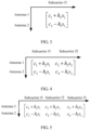
- the D2D transmission data s1 may be multiplexed, and the matrix of the transmission data is shown in FIG. 3 .
- a column of the matrix represents data transmitted over a carrier, and a row of the matrix represents data transmitted on an antenna.
- antenna 1 and antenna 2 transmit data over subcarrier f1 only.
- the D2D transmission data s1 and s2 may be multiplexed, and the matrix of the transmission data is shown in FIG. 4 .
- antenna 1 and antenna 2 transmit data over subcarriers f1 and f2.
- the D2D transmission data s1, s2, and s3 may be multiplexed, and the matrix of the transmission data is shown in FIG. 5 .
- antenna 1 and antenna 2 transmit data over subcarriers f1, f2, and f3.
- transmission matrices constructed under circumstances of more subcarriers may be obtained. The same applies to the transmission over different timeslots.
- a signal relationship in the transmission data may be set properly to make it easier for the receiver to decode and obtain required data.
- the data transmitted to both the first device and the second device is transmitted according to the foregoing data matrix, the data actually received by the first device is different from the data actually received by the second device due to channel difference.
- the signal receiver needs to decode and obtain required signals according to the special relationship of the constructed data.
- FIG. 6 is a specific schematic flowchart of a signal receiving method according to an embodiment of the present invention. This method is applicable to the process in which the first device receives signals, which is described in the signal transmitting method above.
- the method includes the following steps: 201.
- a first device receives data for first antenna and data for second antenna that are transmitted by a mobile terminal, where the data for first antenna comprises first transmission data that needs to be transmitted by the mobile terminal to a local receiver, transmission data that needs to be transmitted to a second device, and a parameter of a transmission channel from a second antenna of the mobile terminal to the first device, and the data for second antenna comprises second transmission data that needs to be transmitted by the mobile terminal to the first device, the transmission data that needs to be transmitted to the second device, and a parameter of a transmission channel from a first antenna of the mobile terminal to the local receiver.
- the data for first antenna and the data for second antenna include data transmitted over one or more subcarriers or data transmitted over one or more timeslots.
- c 2i-1 and c 2i respectively represent first transmission data and second transmission data that need to be transmitted over an i th subcarrier or timeslot to the local receiver
- s i represents transmission data that needs to be transmitted over the i th subcarrier or timeslot to the second device
- h 1 and h 2 respectively represent the parameter of the transmission channel from the first antenna to the local receiver and the parameter of the transmission channel from the second antenna to the local receiver
- m represents the total number of subcarriers or timeslots for transmitting signals
- m is a natural number.
- the transmitted data includes data of more antennas
- the received data includes corresponding data.
- the number of pieces of transmitted antenna data is an even number, the impact of the data transmitted to the second device can be counteracted on the receiver.
- the first device cancels, according to the received data for first antenna, the received data for second antenna, a preset parameter of the transmission channel from the first antenna to the first device, and a preset parameter of the transmission channel from the second antenna to the first device, interference caused by the transmission data that needs to be transmitted to the second device, to the first transmission data and the second transmission data, so as to obtain the first transmission data and the second transmission data.
- data over m carriers is received, and the data is decoded according to different data over subcarriers or timeslots.
- the specific number of subcarriers or timeslots may be agreed with the transmitter beforehand.
- s i represents the transmission data that needs to be transmitted over the i th subcarrier or timeslot to the second device
- h 1 represents the parameter of the transmission channel from the first antenna to the first device
- h 2 represents the parameter of the transmission channel from the second antenna to the first device.
- formula 2 can be solved by using a Space frequence Block Code, SFBC.
- SFBC Space frequence Block Code
- STBC Space time block code
- FIG. 7 is another specific schematic flowchart of a signal receiving method according to an embodiment of the present invention. This method is applied to the process in which the second device receives signals, which is described in the signal transmitting method above.
- the method includes the following steps: 301.
- a second device receives data for first antenna and data for second antenna that are transmitted by a mobile terminal, where the data for first antenna comprises first transmission data that needs to be transmitted by the mobile terminal to a first device, transmission data that needs to be transmitted to the second device, and a parameter of a transmission channel from a second antenna of the mobile terminal to the first device, and the data for second antenna comprises second transmission data that needs to be transmitted by the mobile terminal to the first device, the transmission data that needs to be transmitted to the second device, and a parameter of a transmission channel from a first antenna to the first device.
- the data for first antenna and the data for second antenna that are actually received by the data receiving device are different from the transmitted data for first antenna and data for second antenna due to the impact caused by the transmission channel.
- the data for first antenna and the data for second antenna that are transmitted by the mobile terminal to the second device include data transmitted over one or more subcarriers or data transmitted over one or more timeslots.
- c 2i-1 and c 2i respectively represent first transmission data and second transmission data that need to be transmitted over an i th subcarrier or timeslot to the first device
- s i represents transmission data that needs to be transmitted over the i th subcarrier
- the second device obtains, according to the received data for first antenna, the received data for second antenna, a preset parameter of a transmission channel from the mobile terminal to the second device, and a preset parameter of a transmission channel from the mobile terminal to the second device side, the transmission data that needs to be transmitted by the mobile terminal to the second device.
- Formula 4 includes 4 equations and 4 unknown numbers. Therefore, a method such as a minimum mean square error (Minimum Mean Square Error, MMSE) and successive interference cancellation (Successive interference cancellation, SIC) may be used to calculate transmission data s 1 and s 2 that need to be transmitted to the second device.
- MMSE Minimum Mean Square Error
- SIC Successessive interference cancellation
- the inventor has performed an emulation experiment on the solution disclosed in the embodiment of the present invention. Assuming that the distance of D2D transmission is 10 meters (meters, m), a change of channel capacity is emulated when the distance from a user terminal (User Equipment, UE) to a base station (Base Station, BS) varies from 200 m to 500 m, as shown in FIG. 8 .
- the lower curve in the figure is a channel capacity curve when an existing cellular uplink transmission solution is applied, and the upper curve in the figure is a channel capacity curve when a coordinated transmission solution in the embodiment of the present invention is applied.
- the channel capacity in the solution in the embodiment of the present invention is far higher than the capacity in the existing cellular uplink transmission solution, and is about 50% higher on average.
- an embodiment of the present invention further provides a communication system.
- the system includes a mobile terminal 3, a base station 1, and a terminal device 2 that performs D2D transmission with the mobile terminal, as shown in FIG. 9 .
- the mobile terminal 3 includes a first antenna 31, a second antenna 32, and a data constructing module 33, configured to construct data for first antenna and data for second antenna, where the data for first antenna comprises first transmission data that needs to be transmitted by the first antenna of the mobile terminal to the first device, transmission data that needs to be transmitted by the mobile terminal to the second device, and a parameter of a transmission channel from the second antenna of the mobile terminal to the first device, and the data for second antenna comprises second transmission data that needs to be transmitted by the second antenna of the mobile terminal to the first device, the transmission data that needs to be transmitted by the mobile terminal to the second device, and a parameter of a transmission channel from the first antenna of the mobile terminal to the first device; and a data transmitting module 34, connected to the data constructing module 33, the first antenna 31, and the second antenna 32, and configured to: use the first antenna to transmit the data for first antenna to the first device, and use the second antenna to transmit the data for second antenna to the first device, so that the first device cancel
- the data for first antenna transmitted by the data transmitting module 34 through the first antenna includes data transmitted by the first antenna over one or more subcarriers, and data transmitted over each subcarrier in the data for first antenna comprises first transmission data that needs to be transmitted over the subcarrier to the first device, transmission data that needs to be transmitted over the subcarrier to the second device, and the parameter of the transmission channel from the second antenna to the first device; and the data for second antenna transmitted by the data transmitting module 34 through the second antenna also includes data transmitted by the second antenna over subcarriers, and data transmitted over each subcarrier in the data for second antenna comprises second transmission data that needs to be transmitted over the subcarrier to the first device, transmission data that needs to be transmitted over the subcarrier to the second device, and the parameter of the transmission channel from the first antenna to the first device.
- the data for first antenna transmitted by the data transmitting module 34 through the first antenna includes data transmitted by the first antenna over one or more timeslots of a time domain, and data transmitted over each timeslot in the data for first antenna comprises first transmission data that needs to be transmitted over the timeslot to the first device, transmission data that needs to be transmitted over the timeslot to the second device, and the parameter of the transmission channel from the second antenna to the first device; and the data for second antenna transmitted by the data transmitting module 34 through the second antenna includes data transmitted by the second antenna over one or more timeslots of a time domain, and data transmitted over each timeslot in the data for second antenna comprises second transmission data that needs to be transmitted over the timeslot to the first device, transmission data that needs to be transmitted over the timeslot to the second device, and the parameter of the transmission channel from the first antenna to the first device.
- the mobile terminal 3 may further include a k th antenna and a (k+1) th antenna, where k is a natural number greater than 2.
- the data constructing module 33 is further configured to construct k th antenna data and (k+1) th antenna data, where the k th antenna data comprises k th transmission data that needs to be transmitted to the first device, the transmission data that needs to be transmitted to the second device, and a parameter of a transmission channel from the (k+1) th antenna to the first device, and the (k+1) th antenna data comprises (k+1) th transmission data that needs to be transmitted to the first device, the transmission data that needs to be transmitted to the second device, and a parameter of a transmission channel from the k th antenna to the first device; and the data transmitting module 34 is further connected to the k th antenna and the (k+1) th antenna, and is further configured to: use the k th antenna to transmit the k th antenna data to the first device, and use the (k+1)
- FIG. 12 is a specific schematic structural diagram of a base station according to an embodiment of the present invention.
- the base station 1 may include: a first receiving module 10, configured to receive data for first antenna and data for second antenna that are transmitted by a mobile terminal, where the data for first antenna comprises first transmission data that needs to be transmitted by the mobile terminal to the base station, transmission data that needs to be transmitted to a second device, and a parameter of a transmission channel from a second antenna of the mobile terminal to the base station, and the data for second antenna comprises second transmission data that needs to be transmitted by the mobile terminal to the base station, the transmission data that needs to be transmitted to the second device, and a parameter of a transmission channel from a first antenna of the mobile terminal to the base station; and a first obtaining module 12, configured to cancel, according to the received data for first antenna, the received data for second antenna, a preset parameter of the transmission channel from the first antenna to the base station, and a preset parameter of the transmission channel from the second antenna to the base station, interference caused by the transmission data that needs to
- the data for first antenna and the data for second antenna include data transmitted over one or more subcarriers or data transmitted over one or more timeslots.
- s i represents the transmission data that needs to be transmitted over the i th subcarrier or timeslot to the second device
- h 1 represents the parameter of the transmission channel from the first antenna to the base station
- h 2 represents the parameter of the transmission channel from the second antenna to the base station
- FIG. 13 is a specific schematic structural diagram of a terminal device according to an embodiment of the present invention.
- the terminal device 2 may include: a second receiving module 20, configured to receive data for first antenna and data for second antenna that are transmitted by a mobile terminal, where the data for first antenna comprises first transmission data that needs to be transmitted by the mobile terminal to a first device, transmission data that needs to be transmitted to the terminal device, and a parameter of a transmission channel from a second antenna of the mobile terminal to the first device, and the data for second antenna comprises second transmission data that needs to be transmitted by the mobile terminal to the first device, the transmission data that needs to be transmitted to the terminal device, and a parameter of a transmission channel from a first antenna to the first device; and a second obtaining module 22, configured to obtain, according to the received data for first antenna, the received data for second antenna, a preset parameter of a transmission channel from the mobile terminal to the terminal device, and a preset parameter of a transmission channel from the mobile terminal to the terminal device, the transmission data that needs to be transmitted by the mobile
- the data for first antenna and the data for second antenna include data transmitted over one or more subcarriers or data transmitted over one or more timeslots, and the terminal device further includes a first receiving antenna 21 and a second receiving antenna 23, as shown in FIG. 14 , where
- data transmitted to two terminals is constructed together (for example, D2D transmission data is superposed on cellular transmission spectrum resources, or data transmitted to two base stations or two D2D devices is superposed), and transmitted over the same time-frequency resources, so that the data transmitted to different terminals does not need to occupy different time-frequency resources.
- a transmission data matrix interference between different data transmitted to two terminals (for example, interference caused by D2D transmission to cellular transmission, or interference between data transmitted to two base stations or between data transmitted to two D2D devices), which is caused by data superposition, is cancelled, and system capacity and spectrum efficiency are enhanced.
- the aforementioned program may be stored in a computer readable storage medium. When the program runs, the processes of the foregoing methods in the embodiments are performed.
- the storage medium may be a magnetic disk, an optical disk, a read-only memory (Read-Only Memory, ROM), or a random access memory (Random Access, RAM).
Landscapes
- Engineering & Computer Science (AREA)
- Computer Networks & Wireless Communication (AREA)
- Signal Processing (AREA)
- Mobile Radio Communication Systems (AREA)
- Radio Relay Systems (AREA)
Claims (14)
- Signalübertragungsverfahren, wobei ein mobiles Endgerät eine erste Antenne und eine zweite Antenne umfasst und das mobile Endgerät kommunikativ mit einer ersten Vorrichtung bzw. einer zweiten Vorrichtung verbunden ist, wobei das Verfahren Folgendes umfasst:Konstruieren (101) von Daten für die erste Antenne und Daten für die zweite Antenne durch das mobile Endgerät, wobei die Daten für die erste Antenne erste Übertragungsdaten, die durch die erste Antenne zu der ersten Vorrichtung zu übertragen sind, Übertragungsdaten, die durch das mobile Endgerät zu der zweiten Vorrichtung zu übertragen sind, und einen Parameter eines Übertragungskanals von der zweiten Antenne zu der ersten Vorrichtung umfassen und die Daten für die zweite Antennen zweite Übertragungsdaten, die durch die zweite Antenne zu der ersten Vorrichtung zu übertragen sind, die Übertragungsdaten, die durch das mobile Endgerät zu der zweiten Vorrichtung übertragen werden müssen, und einen Parameter eines Übertragungskanals von der ersten Antenne zu der ersten Vorrichtung umfassen;Übertragen (102) der Daten für die erste Antenne durch das mobile Endgerät mittels der ersten Antenne und Übertragen der Daten für die zweite Antenne durch das mobile Endgerät mittels der zweiten Antenne;wobei die Daten für die erste Antenne und die Daten für die zweite Antenne Daten, die über einen oder mehrere Subträger übertragen werden, oder Daten, die über einen oder mehrere Zeitschlitze übertragen werden, umfassen und das Konstruieren von Daten für die erste Antenne und Daten für die zweite Antenne durch das mobile Endgerät Folgendes umfasst:Erzeugen der Daten für die erste Antenne

 wobei c 2i-1 erste Übertragungsdaten repräsentiert, die über einen i-ten Subträger oder Zeitschlitz zu der ersten Vorrichtung übertragen werden müssen, c 2 i zweite Übertragungsdaten repräsentiert, die über den i-ten Subträger oder Zeitschlitz zu der ersten Vorrichtung übertragen werden müssen, si Übertragungsdaten repräsentiert, die über den i-ten Subträger oder Zeitschlitz zu der zweiten Vorrichtung übertragen werden müssen, h 1 den Parameter des Übertragungskanals von der ersten Antenne zu der ersten Vorrichtung repräsentiert, h 2 den Parameter des Übertragungskanals von der zweiten Antenne zu der ersten Vorrichtung repräsentiert, m die Gesamtzahl von Subträgern oder Zeitschlitzen zum Übertragen von Signalen repräsentiert und m eine natürliche Zahl ist.
 - Verfahren nach Anspruch 1, wobei die Daten für die erste Antenne Daten umfassen, die durch die erste Antenne über einen oder mehrere Subträger übertragen werden, und über jeden Subträger in den Daten für die erste Antenne übertragene Daten erste Übertragungsdaten, die über den Subträger zu der ersten Vorrichtung übertragen werden müssen, Übertragungsdaten, die über den Subträger zu der zweiten Vorrichtung übertragen werden müssen, und den Parameter des Übertragungskanals von der zweiten Antenne zu der ersten Vorrichtung umfassen; und
die Daten für die zweite Antenne Daten umfassen, die durch die zweite Antenne über Subträger übertragen werden, und Daten, die über jeden Subträger in den Daten für die zweite Antenne übertragen werden, zweite Übertragungsdaten, die über den Subträger zu der ersten Vorrichtung übertragen werden müssen, Übertragungsdaten, die über den Subträger zu der zweiten Vorrichtung übertragen werden müssen, und den Parameter des Übertragungskanals von der ersten Antenne zu der ersten Vorrichtung umfassen. - Verfahren nach Anspruch 1, wobei die Daten für die erste Antenne Daten umfassen, die durch die erste Antenne über einen oder mehrere Zeitschlitze eines Zeitbereichs übertragen werden, und über jeden Zeitschlitz in den Daten für die erste Antenne übertragene Daten erste Übertragungsdaten, die über den Zeitschlitz zu der ersten Vorrichtung übertragen werden müssen, Übertragungsdaten, die über den Zeitschlitz zu der zweiten Vorrichtung übertragen werden müssen, und den Parameter des Übertragungskanals von der zweiten Antenne zu der ersten Vorrichtung umfassen; und die Daten für die zweite Antenne Daten umfassen, die durch die zweite Antenne über einen oder mehrere Zeitschlitze eines Zeitbereichs übertragen werden, und über jeden Zeitschlitz in den Daten für die zweite Antenne übertragene Daten zweite Übertragungsdaten, die über den Zeitschlitz zu der ersten Vorrichtung übertragen werden müssen, Übertragungsdaten, die über den Zeitschlitz zu der zweiten Vorrichtung übertragen werden müssen, und den Parameter des Übertragungskanals von der ersten Antenne zu der ersten Vorrichtung umfassen.
- Verfahren nach einem der Ansprüche 1-3, wobeiim Fall m = 2, wenn die Daten für die erste Antenne und die Daten für die zweite Antenne erzeugt werden,

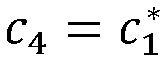 das Verwenden des mobilen Endgeräts der ersten Antenne zum Übertragen der Daten für die erste Antenne und Verwenden des mobilen Endgeräts der zweiten Antenne zum Übertragen der Daten für die zweite Antenne Folgendes umfasst:
Übertragen des mobilen Endgeräts von Daten zu der ersten Vorrichtung und der zweiten Vorrichtung gemäß der folgenden Matrixbeziehung: wobei eine erste Spalte der Matrix Daten repräsentiert, die über einen ersten Subträger oder Zeitschlitz zu der ersten Vorrichtung und der zweiten Vorrichtung übertragen werden, eine zweite Spalte der Matrix Daten repräsentiert, die über einen zweiten Subträger oder Zeitschlitz zu der ersten Vorrichtung und der zweiten Vorrichtung übertragen werden, eine erste Zeile der Matrix Daten repräsentiert, die von der ersten Antenne zu der ersten Vorrichtung und der zweiten Vorrichtung übertragen werden, und eine zweite Zeile der Matrix Daten repräsentiert, die von der zweiten Antenne zu der ersten Vorrichtung und der zweiten Vorrichtung übertragen werden;ein erstes Element in der ersten Spalte der Matrix Daten repräsentiert, die über den ersten Subträger oder Zeitschlitz von der ersten Antenne zu der ersten Vorrichtung und der zweiten Vorrichtung übertragen werden, und ein zweites Element in der ersten Spalte der Matrix Daten repräsentiert, die über den ersten Subträger oder Zeitschlitz von der zweiten Antenne zu der ersten Vorrichtung und der zweiten Vorrichtung übertragen werden; undein erstes Element in der zweiten Spalte der Matrix Daten repräsentiert, die über den zweiten Subträger oder Zeitschlitz von der ersten Antenne zu der ersten Vorrichtung und der zweiten Vorrichtung übertragen werden, und ein zweites Element in der zweiten Spalte der Matrix Daten repräsentiert, die über den zweiten Subträger oder Zeitschlitz von der zweiten Antenne zu der ersten Vorrichtung und der zweiten Vorrichtung übertragen werden.
 - Verfahren nach einem der Ansprüche 1-4, ferner umfassend:Empfangen (201) der Daten für die erste Antenne und der Daten für die zweite Antenne, die durch das mobile Endgerät übertragen werden, durch die erste Vorrichtung; undErhalten (202) der ersten Übertragungsdaten ci und der zweiten Übertragungsdaten c2 durch die erste Vorrichtung gemäß den empfangenen Daten für die erste Antenne, den empfangenen Daten für die zweite Antenne, einem voreingestellten Parameter hi des Übertragungskanals von der ersten Antenne zu der ersten Vorrichtung und einem voreingestellten Parameter h2 des Übertragungskanals von der zweiten Antenne zu der ersten Vorrichtung, mit dem Effekt, dass die durch die Übertragungsdaten, die zu der zweiten Vorrichtung übertragen werden müssen, verursachten Störungen an den ersten Übertragungsdaten und den zweiten Übertragungsdaten gelöscht wurden;wobeidas Empfangen der Daten für die erste Antenne und der Daten für die zweite Antenne, die durch das mobile Endgerät übertragen werden, Folgendes umfasst:
Empfangen von Daten y B über einen

- Verfahren nach Anspruch 5, wobei falls m = 2 ist und die empfangenen Daten c 3 =



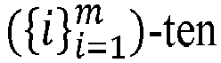
das Erhalten durch die erste Vorrichtung der ersten Übertragungsdaten und der zweiten Übertragungsdaten gemäß den empfangenen Daten für die erste Antenne, den empfangenen Daten für die zweite Antenne, einem voreingestellten Parameter des Übertragungskanals von der ersten Antenne zu der ersten Vorrichtung und einem voreingestellten Parameter des Übertragungskanals von der zweiten Antenne zu der ersten Vorrichtung Folgendes umfasst:Verarbeiten des empfangenen y B, um zu erhalten, wobei

 Erhalten von ci und c 2 durch Berechnung gemäß dem erhaltenen yB, dem bekannten h 1 und h 2 und einer Beziehung zwischen
- Mobiles Endgerät (3), wobei das mobile Endgerät eine erste Antenne (31) und eine zweite Antenne (32) umfasst, das mobile Endgerät (3) kommunikativ mit einer ersten Vorrichtung (1) bzw. einer zweiten Vorrichtung (2) verbunden ist und das mobile Endgerät ferner Folgendes umfasst:ein Datenkonstruktionsmodul (33), ausgelegt zum Konstruieren von Daten für die erste Antenne und Daten für die zweite Antenne, wobei die Daten für die erste Antenne erste Übertragungsdaten, die durch die erste Antenne des mobilen Endgeräts zu der ersten Vorrichtung zu übertragen sind, Übertragungsdaten, die durch das mobile Endgerät zu der zweiten Vorrichtung zu übertragen sind, und einen Parameter eines Übertragungskanals von der zweiten Antenne des mobilen Endgeräts zu der ersten Vorrichtung umfassen und die Daten für die zweite Antenne zweite Übertragungsdaten, die durch die zweite Antenne des mobilen Endgeräts zu der ersten Vorrichtung zu übertragen sind, die Übertragungsdaten, die durch das mobile Endgerät zu der zweiten Vorrichtung übertragen werden müssen, und einen Parameter eines Übertragungskanals von der ersten Antenne des mobilen Endgeräts zu der ersten Vorrichtung umfassen; undein Datenübertragungsmodul (34), das mit dem Datenkonstruktionsmodul (33), der ersten Antenne (31) und der zweiten Antenne (32) verbunden ist und ausgelegt ist zum Übertragen der Daten für die erste Antenne durch die erste Antenne (31) und Übertragen der Daten für die zweite Antenne durch die zweite Antenne (32);wobei die Daten für die erste Antenne und die Daten für die zweite Antenne Daten, die über einen oder mehrere Subträger übertragen werden, oder Daten, die über einen oder mehrere Zeitschlitze übertragen werden, umfassen und das Datenkonstruktionsmodul insbesondere ausgelegt ist, die Daten für die erste Antenne

 wobei c 2i-1 erste Übertragungsdaten repräsentiert, die über einen i-ten Subträger oder Zeitschlitz zu der ersten Vorrichtung übertragen werden müssen, c 2 i zweite Übertragungsdaten repräsentiert, die über den i-ten Subträger oder Zeitschlitz zu der ersten Vorrichtung übertragen werden müssen, si Übertragungsdaten repräsentiert, die über den i-ten Subträger oder Zeitschlitz zu der zweiten Vorrichtung übertragen werden müssen, h 1 den Parameter des Übertragungskanals von der ersten Antenne zu der ersten Vorrichtung repräsentiert, h 2 den Parameter des Übertragungskanals von der zweiten Antenne zu der ersten Vorrichtung repräsentiert, m die Gesamtzahl von Subträgern oder Zeitschlitzen zum Übertragen von Signalen repräsentiert und m eine natürliche Zahl ist.
 - Mobiles Endgerät (3) nach Anspruch 7, wobei die durch das Datenübertragungsmodul (34) mittels der ersten Antenne (31) übertragenen Daten für die erste Antenne Daten umfassen, die durch die erste Antenne (31) über einen oder mehrere Subträger übertragen werden, und über jeden Subträger in den Daten für die erste Antenne übertragene Daten erste Übertragungsdaten, die über den Subträger zu der ersten Vorrichtung übertragen werden müssen, Übertragungsdaten, die über den Subträger zu der zweiten Vorrichtung (2) übertragen werden müssen, und den Parameter des Übertragungskanals von der zweiten Antenne (32) zu der ersten Vorrichtung (1) umfassen; und
die durch das Datenübertragungsmodul (34) mittels der zweiten Antenne (32) übertragenen Daten für die zweite Antenne auch Daten, die durch die zweite Antenne über Subträger übertragen werden, umfassen, und Daten, die über jeden Subträger in den Daten für die zweite Antenne übertragen werden, zweite Übertragungsdaten, die über den Subträger zu der ersten Vorrichtung übertragen werden müssen, Übertragungsdaten, die über den Subträger zu der zweiten Vorrichtung (2) übertragen werden müssen, und den Parameter des Übertragungskanals von der ersten Antenne zu der ersten Vorrichtung (1) umfassen. - Mobiles Endgerät (3) nach Anspruch 7, wobei die Daten für die erste Antenne, die durch das Datenübertragungsmodul mittels der ersten Antenne übertragen werden, Daten umfassen, die durch die erste Antenne über einen oder mehrere Zeitschlitze eines Zeitbereichs übertragen werden, und über jeden Zeitschlitz in den Daten für die erste Antenne übertragene Daten erste Übertragungsdaten, die über den Zeitschlitz zu der ersten Vorrichtung übertragen werden müssen, Übertragungsdaten, die über Zeitschlitz zu der zweiten Vorrichtung übertragen werden müssen, und den Parameter des Übertragungskanals von der zweiten Antenne zu der ersten Vorrichtung umfassen; und
die Daten für die zweite Antenne, die durch das Datenübertragungsmodul mittels der zweiten Antenne übertragen werden, Daten umfassen, die durch die zweite Antenne über einen oder mehrere Zeitschlitze eines Zeitbereichs übertragen werden, und über jeden Zeitschlitz in den Daten für die zweite Antenne übertragene Daten zweite Übertragungsdaten, die über den Zeitschlitz zu der ersten Vorrichtung übertragen werden müssen, Übertragungsdaten, die über den Zeitschlitz zu der zweiten Vorrichtung übertragen werden müssen, und den Parameter des Übertragungskanals von der ersten Antenne zu der ersten Vorrichtung umfassen. - Mobiles Endgerät (3) nach einem der Ansprüche 7-9, wobeiim Fall m = 2, wenn die Daten für die erste Antenne und die Daten für die zweite Antenne erzeugt werden,

 das Verwenden der ersten Antenne zum Übertragen der Daten für die erste Antenne und Verwenden der zweiten Antenne zum Übertragen der Daten für die zweite Antenne Folgendes umfasst:
das Datenübertragungsmodul ist ausgelegt zum Übertragen von Daten zu der ersten Vorrichtung und der zweiten Vorrichtung gemäß der folgenden Matrixbeziehung: wobei eine erste Spalte der Matrix Daten repräsentiert, die über einen ersten Subträger oder Zeitschlitz zu der ersten Vorrichtung und der zweiten Vorrichtung übertragen werden, eine zweite Spalte der Matrix Daten repräsentiert, die über einen zweiten Subträger oder Zeitschlitz zu der ersten Vorrichtung und der zweiten Vorrichtung übertragen werden, eine erste Zeile der Matrix Daten repräsentiert, die von der ersten Antenne zu der ersten Vorrichtung und der zweiten Vorrichtung übertragen werden, und eine zweite Zeile der Matrix Daten repräsentiert, die von der zweiten Antenne zu der ersten Vorrichtung und der zweiten Vorrichtung übertragen werden;ein erstes Element in der ersten Spalte der Matrix Daten repräsentiert, die über den ersten Subträger oder Zeitschlitz von der ersten Antenne zu der ersten Vorrichtung und der zweiten Vorrichtung übertragen werden, und ein zweites Element in der ersten Spalte der Matrix Daten repräsentiert, die über den ersten Subträger oder Zeitschlitz von der zweiten Antenne zu der ersten Vorrichtung und der zweiten Vorrichtung übertragen werden; undein erstes Element in der zweiten Spalte der Matrix Daten repräsentiert, die über den zweiten Subträger oder Zeitschlitz von der ersten Antenne zu der ersten Vorrichtung und der zweiten Vorrichtung übertragen werden, und ein zweites Element in der zweiten Spalte der Matrix Daten repräsentiert, die über den zweiten Subträger oder Zeitschlitz von der zweiten Antenne zu der ersten Vorrichtung und der zweiten Vorrichtung übertragen werden.
 - System, das ein mobiles Endgerät nach einem der Ansprüche 7-10 und eine Kommunikationsvorrichtung (1, 2), angewandt auf ein Mobilfunk-Übertragungsnetzwerk, umfasst, wobei die Kommunikationsvorrichtung (1, 2) Folgendes umfasst:ein Empfangsmodul (10, 20), ausgelegt zum Empfangen der Daten für die erste Antenne und der Daten für die zweite Antenne, die durch das mobile Endgerät übertragen werden; undein Erhaltemodul (12, 22), ausgelegt zum Erhalten der ersten Übertragungsdaten ci und der zweiten Übertragungsdaten c2 gemäß den empfangenen Daten für die erste Antenne, den empfangenen Daten für die zweite Antenne, einem voreingestellten Parameter hi des Übertragungskanals von der ersten Antenne zu der Basisstation und einem voreingestellten Parameter h2 des Übertragungskanals von der zweiten Antenne zu der Basisstation, mit dem Effekt, dass die durch die Übertragungsdaten, die zu der zweiten Vorrichtung übertragen werden müssen, verursachten Störungen an den ersten Übertragungsdaten und den zweiten Übertragungsdaten gelöscht wurden;wobeidas Empfangsmodul ferner ausgelegt ist zum Empfangen von Daten y B über einen


- System nach Anspruch 11, wobei falls m = 2 ist und die empfangenen Daten
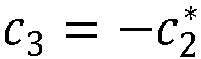


 das Erhaltemodul ferner ausgelegt ist zum Verarbeiten des empfangenen y B, um
 zu erhalten, wobei


 Erhalten von c 1 und c 2 durch Berechnung gemäß dem erhaltenen

- Computerlesbares Speicherungsmedium, wobei das Computerspeicherungsmedium ein Computerprogramm speichert, das, wenn es durch einen Computer ausgeführt wird, bewirkt, dass der Computer das Verfahren nach einem der Ansprüche 1 bis 4 ausführt.
- Programmprodukt, dass ein Computerprogramm umfasst, das, wenn es durch einen Computer ausgeführt wird, bewirkt, dass der Computer das Verfahren nach einem der Ansprüche 1 bis 4 ausführt.
Applications Claiming Priority (2)
| Application Number | Priority Date | Filing Date | Title |
|---|---|---|---|
| CN201210405982.3A CN103780290B (zh) | 2012-10-23 | 2012-10-23 | 一种联合数据信号收发方法和设备 |
| PCT/CN2013/074076 WO2014063472A1 (zh) | 2012-10-23 | 2013-04-11 | 一种联合数据信号收发方法和设备 |
Publications (3)
| Publication Number | Publication Date |
|---|---|
| EP2905912A1 EP2905912A1 (de) | 2015-08-12 |
| EP2905912A4 EP2905912A4 (de) | 2015-10-21 |
| EP2905912B1 true EP2905912B1 (de) | 2024-06-12 |
Family
ID=50543948
Family Applications (1)
| Application Number | Title | Priority Date | Filing Date |
|---|---|---|---|
| EP13849397.8A Active EP2905912B1 (de) | 2012-10-23 | 2013-04-11 | Kombinierte datensignalempfangs- und sendeverfahren sowie vorrichtungen |
Country Status (6)
| Country | Link |
|---|---|
| US (1) | US10075254B2 (de) |
| EP (1) | EP2905912B1 (de) |
| CN (1) | CN103780290B (de) |
| BR (1) | BR112015009043A2 (de) |
| RU (1) | RU2608184C2 (de) |
| WO (1) | WO2014063472A1 (de) |
Families Citing this family (14)
| Publication number | Priority date | Publication date | Assignee | Title |
|---|---|---|---|---|
| US9860774B2 (en) * | 2014-08-18 | 2018-01-02 | Rohde & Schwarz Gmbh & Co. Kg | Test apparatus, radio communication test apparatus, method for testing and computer program product |
| DE102017001543A1 (de) * | 2017-02-16 | 2018-08-16 | Kathrein-Werke Kg | Antenne, insbesondere Mobilfunkantenne |
| US12293583B2 (en) | 2018-02-20 | 2025-05-06 | Arlo Technologies, Inc. | Notification priority sequencing for video security |
| US11064208B2 (en) | 2018-02-20 | 2021-07-13 | Arlo Technologies, Inc. | Transcoding in security camera applications |
| US10805613B2 (en) * | 2018-02-20 | 2020-10-13 | Netgear, Inc. | Systems and methods for optimization and testing of wireless devices |
| US11272189B2 (en) | 2018-02-20 | 2022-03-08 | Netgear, Inc. | Adaptive encoding in security camera applications |
| US10742998B2 (en) | 2018-02-20 | 2020-08-11 | Netgear, Inc. | Transmission rate control of data communications in a wireless camera system |
| US12587657B2 (en) | 2018-02-20 | 2026-03-24 | Arlo Technologies, Inc. | Transcoding in security camera applications |
| US12695884B2 (en) | 2018-02-20 | 2026-07-28 | Arlo Technologies, Inc. | Multi-sensor motion detection |
| US11756390B2 (en) | 2018-02-20 | 2023-09-12 | Arlo Technologies, Inc. | Notification priority sequencing for video security |
| US11102492B2 (en) | 2018-02-20 | 2021-08-24 | Arlo Technologies, Inc. | Multi-sensor motion detection |
| US11076161B2 (en) | 2018-02-20 | 2021-07-27 | Arlo Technologies, Inc. | Notification priority sequencing for video security |
| US11558626B2 (en) | 2018-02-20 | 2023-01-17 | Netgear, Inc. | Battery efficient wireless network connection and registration for a low-power device |
| CN110430554B (zh) * | 2019-06-28 | 2023-11-07 | 维沃移动通信有限公司 | 业务传输方法及终端设备 |
Family Cites Families (15)
| Publication number | Priority date | Publication date | Assignee | Title |
|---|---|---|---|---|
| US6173005B1 (en) * | 1997-09-04 | 2001-01-09 | Motorola, Inc. | Apparatus and method for transmitting signals in a communication system |
| US6212368B1 (en) * | 1998-05-27 | 2001-04-03 | Ericsson Inc. | Measurement techniques for diversity and inter-frequency mobile assisted handoff (MAHO) |
| US6937843B2 (en) * | 2001-12-05 | 2005-08-30 | Lucent Technologies Inc. | Wireless communication system with interference compensation |
| US7512096B2 (en) * | 2004-11-24 | 2009-03-31 | Alcatel-Lucent Usa Inc. | Communicating data between an access point and multiple wireless devices over a link |
| US7428268B2 (en) * | 2004-12-07 | 2008-09-23 | Adaptix, Inc. | Cooperative MIMO in multicell wireless networks |
| US7920522B2 (en) * | 2006-09-29 | 2011-04-05 | Qualcomm Incorporated | Method and apparatus for system interoperability in wireless communications |
| US8099043B2 (en) * | 2008-05-13 | 2012-01-17 | Electronics And Telecommunications Research Institute | Transmit channel in wideband high frequency wireless system using multiple transmit antenna, and method thereof |
| EP2389733A4 (de) * | 2009-01-23 | 2017-03-08 | Nokia Technologies Oy | Störungsunterdrückung bei kommunikationen zwischen geräten |
| CN102439864B (zh) * | 2009-03-31 | 2014-12-17 | 新加坡科技研究局 | 消息传输方法、信息存储方法及消息传输设备、信息存储设备 |
| US8966090B2 (en) | 2009-04-15 | 2015-02-24 | Nokia Corporation | Method, apparatus and computer program product for providing an indication of device to device communication availability |
| KR101559295B1 (ko) * | 2009-12-04 | 2015-10-12 | 삼성전자주식회사 | 공간 분할 다중 사용자 다중 입력 다중 출력 방식을 이용하는 통신 시스템 |
| US9282585B2 (en) * | 2010-11-12 | 2016-03-08 | Nokia Technologies Oy | Method and apparatus for device to device communication |
| KR101607416B1 (ko) * | 2011-11-07 | 2016-03-29 | 모토로라 모빌리티 엘엘씨 | 조정된 멀티-포인트 전송을 이용한 직교 주파수 분할 멀티플렉싱 통신 시스템에서의 공동 프로세싱 방식을 위한 csi 피드백을 위한 방법 및 장치 |
| CN103384161B (zh) | 2012-05-02 | 2018-02-06 | 华为技术有限公司 | Mimo无线通信系统、传输方法和装置 |
| US9531457B2 (en) * | 2012-07-18 | 2016-12-27 | Kyocera Corporation | Interference management of device-to-device communication in a cellular communication system |
-
2012
- 2012-10-23 CN CN201210405982.3A patent/CN103780290B/zh active Active
-
2013
- 2013-04-11 WO PCT/CN2013/074076 patent/WO2014063472A1/zh not_active Ceased
- 2013-04-11 EP EP13849397.8A patent/EP2905912B1/de active Active
- 2013-04-11 RU RU2015119469A patent/RU2608184C2/ru active
- 2013-04-11 BR BR112015009043A patent/BR112015009043A2/pt not_active IP Right Cessation
-
2015
- 2015-04-22 US US14/692,891 patent/US10075254B2/en active Active
Also Published As
| Publication number | Publication date |
|---|---|
| US20150229426A1 (en) | 2015-08-13 |
| RU2608184C2 (ru) | 2017-01-17 |
| RU2015119469A (ru) | 2016-12-20 |
| EP2905912A4 (de) | 2015-10-21 |
| EP2905912A1 (de) | 2015-08-12 |
| CN103780290A (zh) | 2014-05-07 |
| WO2014063472A1 (zh) | 2014-05-01 |
| BR112015009043A2 (pt) | 2017-07-04 |
| CN103780290B (zh) | 2018-11-06 |
| US10075254B2 (en) | 2018-09-11 |
Similar Documents
| Publication | Publication Date | Title |
|---|---|---|
| US10075254B2 (en) | Data signal coordinated transmitting and receiving methods and apparatus | |
| EP2836039B1 (de) | Drahtloses mimo-kommunikationssystem, übertragungsverfahren und vorrichtung | |
| EP3035556B1 (de) | Verfahren und vorrichtung zur übertragung eines gemeinsamen signals in hybrider strahlformung | |
| EP1958351B1 (de) | Punkt-zu-mehrpunkt-einrichtung zur kommunikation mit mehreren telekommunikationseinheiten | |
| US20230283332A1 (en) | Precoding techniques for wireless communications | |
| US10230446B2 (en) | Method and apparatus for transmitting diversity | |
| CN103138822B (zh) | 传输信号的方法和设备 | |
| EP2728768B1 (de) | Sendediversitätsverfahren sowie vorrichtung und system dafür | |
| EP2505009A1 (de) | Kooperative kommunikation in mobilfunknetzen | |
| JP5765758B2 (ja) | 通信装置、通信方法、および通信システム | |
| WO2013151405A1 (ko) | 무선 접속 시스템에서 협력적 프리코딩 방법 및 이를 위한 장치 | |
| CN115398853A (zh) | 用于新无线电中的参考信号时域相干性的参考信号相位时间漂移模型报告 | |
| EP2611258B1 (de) | Verfahren, vorrichtung und system zur verarbeitung von datenübertragungen | |
| Gao et al. | Blind distributed MU-MIMO for IoT networking over VHF narrowband spectrum | |
| EP2485423B1 (de) | Präkodierungsverfahren in einem kooperativen relaissystem, kommunikationsvorrichtung und relaisvorrichtung | |
| EP3267616B1 (de) | Drahtloskommunikationssystem, basisstation und endgerät | |
| Silard et al. | Frequency reuse in iab-based 5g networks using graph coloring methods | |
| RU2589314C1 (ru) | Способ, система и устройство передачи сигнала | |
| KR20160132595A (ko) | 전이중 방식을 지원하는 무선통신 시스템에서 단말 간의 간섭 신호를 제거하고 하향링크 다이버시티 이득을 증가시키는 위한 방법 및 이를 위한 장치 | |
| Manea et al. | MIMO systems in 5G: A review | |
| Chen et al. | A novel interference suppression method in wireless relay networks | |
| Badis et al. | Performance evaluation of MIMO-based MAC/PHY cross-layer design in multi-hop ad hoc networks | |
| EP2942997B1 (de) | Uplink-interferenzunterdrückungsverfahren und vorrichtung | |
| Li et al. | Power threshold based interference alignment in hybrid D2D & cellular uplink transmissions | |
| Simovska et al. | 184. 5G NEW RADIO (5G NR)-AIR INTERFACE IN 5G MOBILE NETWORKS |
Legal Events
| Date | Code | Title | Description |
|---|---|---|---|
| PUAI | Public reference made under article 153(3) epc to a published international application that has entered the european phase |
Free format text: ORIGINAL CODE: 0009012 |
|
| 17P | Request for examination filed |
Effective date: 20150505 |
|
| AK | Designated contracting states |
Kind code of ref document: A1 Designated state(s): AL AT BE BG CH CY CZ DE DK EE ES FI FR GB GR HR HU IE IS IT LI LT LU LV MC MK MT NL NO PL PT RO RS SE SI SK SM TR |
|
| AX | Request for extension of the european patent |
Extension state: BA ME |
|
| RA4 | Supplementary search report drawn up and despatched (corrected) |
Effective date: 20150918 |
|
| RIC1 | Information provided on ipc code assigned before grant |
Ipc: H04W 28/06 20090101ALI20150914BHEP Ipc: H04B 7/26 20060101AFI20150914BHEP Ipc: H04J 11/00 20060101ALI20150914BHEP Ipc: H04B 7/02 20060101ALI20150914BHEP Ipc: H04W 72/04 20090101ALI20150914BHEP |
|
| DAX | Request for extension of the european patent (deleted) | ||
| STAA | Information on the status of an ep patent application or granted ep patent |
Free format text: STATUS: EXAMINATION IS IN PROGRESS |
|
| 17Q | First examination report despatched |
Effective date: 20191202 |
|
| GRAP | Despatch of communication of intention to grant a patent |
Free format text: ORIGINAL CODE: EPIDOSNIGR1 |
|
| STAA | Information on the status of an ep patent application or granted ep patent |
Free format text: STATUS: GRANT OF PATENT IS INTENDED |
|
| RIC1 | Information provided on ipc code assigned before grant |
Ipc: H04W 28/06 20090101ALI20231217BHEP Ipc: H04B 7/06 20060101ALI20231217BHEP Ipc: H04B 7/026 20170101ALI20231217BHEP Ipc: H04J 11/00 20060101ALI20231217BHEP Ipc: H04B 7/26 20060101AFI20231217BHEP |
|
| INTG | Intention to grant announced |
Effective date: 20240110 |
|
| GRAS | Grant fee paid |
Free format text: ORIGINAL CODE: EPIDOSNIGR3 |
|
| GRAA | (expected) grant |
Free format text: ORIGINAL CODE: 0009210 |
|
| STAA | Information on the status of an ep patent application or granted ep patent |
Free format text: STATUS: THE PATENT HAS BEEN GRANTED |
|
| AK | Designated contracting states |
Kind code of ref document: B1 Designated state(s): AL AT BE BG CH CY CZ DE DK EE ES FI FR GB GR HR HU IE IS IT LI LT LU LV MC MK MT NL NO PL PT RO RS SE SI SK SM TR |
|
| REG | Reference to a national code |
Ref country code: GB Ref legal event code: FG4D |
|
| REG | Reference to a national code |
Ref country code: CH Ref legal event code: EP |
|
| REG | Reference to a national code |
Ref country code: DE Ref legal event code: R096 Ref document number: 602013085799 Country of ref document: DE |
|
| REG | Reference to a national code |
Ref country code: IE Ref legal event code: FG4D |
|
| PG25 | Lapsed in a contracting state [announced via postgrant information from national office to epo] |
Ref country code: BG Free format text: LAPSE BECAUSE OF FAILURE TO SUBMIT A TRANSLATION OF THE DESCRIPTION OR TO PAY THE FEE WITHIN THE PRESCRIBED TIME-LIMIT Effective date: 20240612 |
|
| PG25 | Lapsed in a contracting state [announced via postgrant information from national office to epo] |
Ref country code: FI Free format text: LAPSE BECAUSE OF FAILURE TO SUBMIT A TRANSLATION OF THE DESCRIPTION OR TO PAY THE FEE WITHIN THE PRESCRIBED TIME-LIMIT Effective date: 20240612 Ref country code: HR Free format text: LAPSE BECAUSE OF FAILURE TO SUBMIT A TRANSLATION OF THE DESCRIPTION OR TO PAY THE FEE WITHIN THE PRESCRIBED TIME-LIMIT Effective date: 20240612 |
|
| REG | Reference to a national code |
Ref country code: LT Ref legal event code: MG9D |
|
| PG25 | Lapsed in a contracting state [announced via postgrant information from national office to epo] |
Ref country code: GR Free format text: LAPSE BECAUSE OF FAILURE TO SUBMIT A TRANSLATION OF THE DESCRIPTION OR TO PAY THE FEE WITHIN THE PRESCRIBED TIME-LIMIT Effective date: 20240913 |
|
| REG | Reference to a national code |
Ref country code: NL Ref legal event code: MP Effective date: 20240612 |
|
| PG25 | Lapsed in a contracting state [announced via postgrant information from national office to epo] |
Ref country code: ES Free format text: LAPSE BECAUSE OF FAILURE TO SUBMIT A TRANSLATION OF THE DESCRIPTION OR TO PAY THE FEE WITHIN THE PRESCRIBED TIME-LIMIT Effective date: 20240612 |
|
| PG25 | Lapsed in a contracting state [announced via postgrant information from national office to epo] |
Ref country code: LV Free format text: LAPSE BECAUSE OF FAILURE TO SUBMIT A TRANSLATION OF THE DESCRIPTION OR TO PAY THE FEE WITHIN THE PRESCRIBED TIME-LIMIT Effective date: 20240612 |
|
| PG25 | Lapsed in a contracting state [announced via postgrant information from national office to epo] |
Ref country code: NO Free format text: LAPSE BECAUSE OF FAILURE TO SUBMIT A TRANSLATION OF THE DESCRIPTION OR TO PAY THE FEE WITHIN THE PRESCRIBED TIME-LIMIT Effective date: 20240912 Ref country code: LV Free format text: LAPSE BECAUSE OF FAILURE TO SUBMIT A TRANSLATION OF THE DESCRIPTION OR TO PAY THE FEE WITHIN THE PRESCRIBED TIME-LIMIT Effective date: 20240612 Ref country code: HR Free format text: LAPSE BECAUSE OF FAILURE TO SUBMIT A TRANSLATION OF THE DESCRIPTION OR TO PAY THE FEE WITHIN THE PRESCRIBED TIME-LIMIT Effective date: 20240612 Ref country code: GR Free format text: LAPSE BECAUSE OF FAILURE TO SUBMIT A TRANSLATION OF THE DESCRIPTION OR TO PAY THE FEE WITHIN THE PRESCRIBED TIME-LIMIT Effective date: 20240913 Ref country code: FI Free format text: LAPSE BECAUSE OF FAILURE TO SUBMIT A TRANSLATION OF THE DESCRIPTION OR TO PAY THE FEE WITHIN THE PRESCRIBED TIME-LIMIT Effective date: 20240612 Ref country code: ES Free format text: LAPSE BECAUSE OF FAILURE TO SUBMIT A TRANSLATION OF THE DESCRIPTION OR TO PAY THE FEE WITHIN THE PRESCRIBED TIME-LIMIT Effective date: 20240612 Ref country code: BG Free format text: LAPSE BECAUSE OF FAILURE TO SUBMIT A TRANSLATION OF THE DESCRIPTION OR TO PAY THE FEE WITHIN THE PRESCRIBED TIME-LIMIT Effective date: 20240612 Ref country code: RS Free format text: LAPSE BECAUSE OF FAILURE TO SUBMIT A TRANSLATION OF THE DESCRIPTION OR TO PAY THE FEE WITHIN THE PRESCRIBED TIME-LIMIT Effective date: 20240912 |
|
| PG25 | Lapsed in a contracting state [announced via postgrant information from national office to epo] |
Ref country code: NL Free format text: LAPSE BECAUSE OF FAILURE TO SUBMIT A TRANSLATION OF THE DESCRIPTION OR TO PAY THE FEE WITHIN THE PRESCRIBED TIME-LIMIT Effective date: 20240612 |
|
| REG | Reference to a national code |
Ref country code: AT Ref legal event code: MK05 Ref document number: 1695089 Country of ref document: AT Kind code of ref document: T Effective date: 20240612 |
|
| PG25 | Lapsed in a contracting state [announced via postgrant information from national office to epo] |
Ref country code: NL Free format text: LAPSE BECAUSE OF FAILURE TO SUBMIT A TRANSLATION OF THE DESCRIPTION OR TO PAY THE FEE WITHIN THE PRESCRIBED TIME-LIMIT Effective date: 20240612 |
|
| PG25 | Lapsed in a contracting state [announced via postgrant information from national office to epo] |
Ref country code: PT Free format text: LAPSE BECAUSE OF FAILURE TO SUBMIT A TRANSLATION OF THE DESCRIPTION OR TO PAY THE FEE WITHIN THE PRESCRIBED TIME-LIMIT Effective date: 20241014 |
|
| PG25 | Lapsed in a contracting state [announced via postgrant information from national office to epo] |
Ref country code: PT Free format text: LAPSE BECAUSE OF FAILURE TO SUBMIT A TRANSLATION OF THE DESCRIPTION OR TO PAY THE FEE WITHIN THE PRESCRIBED TIME-LIMIT Effective date: 20241014 |
|
| PG25 | Lapsed in a contracting state [announced via postgrant information from national office to epo] |
Ref country code: PL Free format text: LAPSE BECAUSE OF FAILURE TO SUBMIT A TRANSLATION OF THE DESCRIPTION OR TO PAY THE FEE WITHIN THE PRESCRIBED TIME-LIMIT Effective date: 20240612 |
|
| PG25 | Lapsed in a contracting state [announced via postgrant information from national office to epo] |
Ref country code: EE Free format text: LAPSE BECAUSE OF FAILURE TO SUBMIT A TRANSLATION OF THE DESCRIPTION OR TO PAY THE FEE WITHIN THE PRESCRIBED TIME-LIMIT Effective date: 20240612 |
|
| PG25 | Lapsed in a contracting state [announced via postgrant information from national office to epo] |
Ref country code: AT Free format text: LAPSE BECAUSE OF FAILURE TO SUBMIT A TRANSLATION OF THE DESCRIPTION OR TO PAY THE FEE WITHIN THE PRESCRIBED TIME-LIMIT Effective date: 20240612 Ref country code: IS Free format text: LAPSE BECAUSE OF FAILURE TO SUBMIT A TRANSLATION OF THE DESCRIPTION OR TO PAY THE FEE WITHIN THE PRESCRIBED TIME-LIMIT Effective date: 20241012 |
|
| PG25 | Lapsed in a contracting state [announced via postgrant information from national office to epo] |
Ref country code: CZ Free format text: LAPSE BECAUSE OF FAILURE TO SUBMIT A TRANSLATION OF THE DESCRIPTION OR TO PAY THE FEE WITHIN THE PRESCRIBED TIME-LIMIT Effective date: 20240612 |
|
| PG25 | Lapsed in a contracting state [announced via postgrant information from national office to epo] |
Ref country code: SK Free format text: LAPSE BECAUSE OF FAILURE TO SUBMIT A TRANSLATION OF THE DESCRIPTION OR TO PAY THE FEE WITHIN THE PRESCRIBED TIME-LIMIT Effective date: 20240612 Ref country code: RO Free format text: LAPSE BECAUSE OF FAILURE TO SUBMIT A TRANSLATION OF THE DESCRIPTION OR TO PAY THE FEE WITHIN THE PRESCRIBED TIME-LIMIT Effective date: 20240612 |
|
| PG25 | Lapsed in a contracting state [announced via postgrant information from national office to epo] |
Ref country code: SM Free format text: LAPSE BECAUSE OF FAILURE TO SUBMIT A TRANSLATION OF THE DESCRIPTION OR TO PAY THE FEE WITHIN THE PRESCRIBED TIME-LIMIT Effective date: 20240612 |
|
| PG25 | Lapsed in a contracting state [announced via postgrant information from national office to epo] |
Ref country code: SM Free format text: LAPSE BECAUSE OF FAILURE TO SUBMIT A TRANSLATION OF THE DESCRIPTION OR TO PAY THE FEE WITHIN THE PRESCRIBED TIME-LIMIT Effective date: 20240612 Ref country code: SK Free format text: LAPSE BECAUSE OF FAILURE TO SUBMIT A TRANSLATION OF THE DESCRIPTION OR TO PAY THE FEE WITHIN THE PRESCRIBED TIME-LIMIT Effective date: 20240612 Ref country code: RO Free format text: LAPSE BECAUSE OF FAILURE TO SUBMIT A TRANSLATION OF THE DESCRIPTION OR TO PAY THE FEE WITHIN THE PRESCRIBED TIME-LIMIT Effective date: 20240612 Ref country code: PL Free format text: LAPSE BECAUSE OF FAILURE TO SUBMIT A TRANSLATION OF THE DESCRIPTION OR TO PAY THE FEE WITHIN THE PRESCRIBED TIME-LIMIT Effective date: 20240612 Ref country code: IS Free format text: LAPSE BECAUSE OF FAILURE TO SUBMIT A TRANSLATION OF THE DESCRIPTION OR TO PAY THE FEE WITHIN THE PRESCRIBED TIME-LIMIT Effective date: 20241012 Ref country code: EE Free format text: LAPSE BECAUSE OF FAILURE TO SUBMIT A TRANSLATION OF THE DESCRIPTION OR TO PAY THE FEE WITHIN THE PRESCRIBED TIME-LIMIT Effective date: 20240612 Ref country code: CZ Free format text: LAPSE BECAUSE OF FAILURE TO SUBMIT A TRANSLATION OF THE DESCRIPTION OR TO PAY THE FEE WITHIN THE PRESCRIBED TIME-LIMIT Effective date: 20240612 Ref country code: AT Free format text: LAPSE BECAUSE OF FAILURE TO SUBMIT A TRANSLATION OF THE DESCRIPTION OR TO PAY THE FEE WITHIN THE PRESCRIBED TIME-LIMIT Effective date: 20240612 |
|
| PG25 | Lapsed in a contracting state [announced via postgrant information from national office to epo] |
Ref country code: IT Free format text: LAPSE BECAUSE OF FAILURE TO SUBMIT A TRANSLATION OF THE DESCRIPTION OR TO PAY THE FEE WITHIN THE PRESCRIBED TIME-LIMIT Effective date: 20240612 |
|
| REG | Reference to a national code |
Ref country code: DE Ref legal event code: R097 Ref document number: 602013085799 Country of ref document: DE |
|
| PG25 | Lapsed in a contracting state [announced via postgrant information from national office to epo] |
Ref country code: DK Free format text: LAPSE BECAUSE OF FAILURE TO SUBMIT A TRANSLATION OF THE DESCRIPTION OR TO PAY THE FEE WITHIN THE PRESCRIBED TIME-LIMIT Effective date: 20240612 |
|
| PLBE | No opposition filed within time limit |
Free format text: ORIGINAL CODE: 0009261 |
|
| STAA | Information on the status of an ep patent application or granted ep patent |
Free format text: STATUS: NO OPPOSITION FILED WITHIN TIME LIMIT |
|
| 26N | No opposition filed |
Effective date: 20250313 |
|
| PG25 | Lapsed in a contracting state [announced via postgrant information from national office to epo] |
Ref country code: SE Free format text: LAPSE BECAUSE OF FAILURE TO SUBMIT A TRANSLATION OF THE DESCRIPTION OR TO PAY THE FEE WITHIN THE PRESCRIBED TIME-LIMIT Effective date: 20240612 |
|
| REG | Reference to a national code |
Ref country code: CH Ref legal event code: H13 Free format text: ST27 STATUS EVENT CODE: U-0-0-H10-H13 (AS PROVIDED BY THE NATIONAL OFFICE) Effective date: 20251125 |
|
| PG25 | Lapsed in a contracting state [announced via postgrant information from national office to epo] |
Ref country code: LU Free format text: LAPSE BECAUSE OF NON-PAYMENT OF DUE FEES Effective date: 20250411 |
|
| PG25 | Lapsed in a contracting state [announced via postgrant information from national office to epo] |
Ref country code: MC Free format text: LAPSE BECAUSE OF FAILURE TO SUBMIT A TRANSLATION OF THE DESCRIPTION OR TO PAY THE FEE WITHIN THE PRESCRIBED TIME-LIMIT Effective date: 20240612 |
|
| GBPC | Gb: european patent ceased through non-payment of renewal fee |
Effective date: 20250411 |
|
| REG | Reference to a national code |
Ref country code: BE Ref legal event code: MM Effective date: 20250430 |
|
| PG25 | Lapsed in a contracting state [announced via postgrant information from national office to epo] |
Ref country code: GB Free format text: LAPSE BECAUSE OF NON-PAYMENT OF DUE FEES Effective date: 20250411 |
|
| PG25 | Lapsed in a contracting state [announced via postgrant information from national office to epo] |
Ref country code: FR Free format text: LAPSE BECAUSE OF NON-PAYMENT OF DUE FEES Effective date: 20250430 |
|
| PG25 | Lapsed in a contracting state [announced via postgrant information from national office to epo] |
Ref country code: BE Free format text: LAPSE BECAUSE OF NON-PAYMENT OF DUE FEES Effective date: 20250430 |
|
| PG25 | Lapsed in a contracting state [announced via postgrant information from national office to epo] |
Ref country code: CH Free format text: LAPSE BECAUSE OF NON-PAYMENT OF DUE FEES Effective date: 20250430 |
|
| PG25 | Lapsed in a contracting state [announced via postgrant information from national office to epo] |
Ref country code: IE Free format text: LAPSE BECAUSE OF NON-PAYMENT OF DUE FEES Effective date: 20250411 |
|
| PG25 | Lapsed in a contracting state [announced via postgrant information from national office to epo] |
Ref country code: CY Free format text: LAPSE BECAUSE OF FAILURE TO SUBMIT A TRANSLATION OF THE DESCRIPTION OR TO PAY THE FEE WITHIN THE PRESCRIBED TIME-LIMIT Effective date: 20240612 |
|
| PG25 | Lapsed in a contracting state [announced via postgrant information from national office to epo] |
Ref country code: LT Free format text: LAPSE BECAUSE OF FAILURE TO SUBMIT A TRANSLATION OF THE DESCRIPTION OR TO PAY THE FEE WITHIN THE PRESCRIBED TIME-LIMIT Effective date: 20240612 |
|
| PGFP | Annual fee paid to national office [announced via postgrant information from national office to epo] |
Ref country code: DE Payment date: 20260305 Year of fee payment: 14 |