EP2905926A1 - Kommunikationssystem, vorrichtung zur verwaltung virtueller netzwerke, verfahren zur verwaltung virtueller netzwerke und programm - Google Patents
Kommunikationssystem, vorrichtung zur verwaltung virtueller netzwerke, verfahren zur verwaltung virtueller netzwerke und programm Download PDFInfo
- Publication number
- EP2905926A1 EP2905926A1 EP13843992.2A EP13843992A EP2905926A1 EP 2905926 A1 EP2905926 A1 EP 2905926A1 EP 13843992 A EP13843992 A EP 13843992A EP 2905926 A1 EP2905926 A1 EP 2905926A1
- Authority
- EP
- European Patent Office
- Prior art keywords
- layer
- network
- user
- network configuration
- configuration information
- Prior art date
- Legal status (The legal status is an assumption and is not a legal conclusion. Google has not performed a legal analysis and makes no representation as to the accuracy of the status listed.)
- Granted
Links
Images





Classifications
-
- H—ELECTRICITY
- H04—ELECTRIC COMMUNICATION TECHNIQUE
- H04L—TRANSMISSION OF DIGITAL INFORMATION, e.g. TELEGRAPHIC COMMUNICATION
- H04L41/00—Arrangements for maintenance, administration or management of data switching networks, e.g. of packet switching networks
- H04L41/04—Network management architectures or arrangements
- H04L41/044—Network management architectures or arrangements comprising hierarchical management structures
-
- H—ELECTRICITY
- H04—ELECTRIC COMMUNICATION TECHNIQUE
- H04L—TRANSMISSION OF DIGITAL INFORMATION, e.g. TELEGRAPHIC COMMUNICATION
- H04L41/00—Arrangements for maintenance, administration or management of data switching networks, e.g. of packet switching networks
- H04L41/28—Restricting access to network management systems or functions, e.g. using authorisation function to access network configuration
-
- H—ELECTRICITY
- H04—ELECTRIC COMMUNICATION TECHNIQUE
- H04L—TRANSMISSION OF DIGITAL INFORMATION, e.g. TELEGRAPHIC COMMUNICATION
- H04L41/00—Arrangements for maintenance, administration or management of data switching networks, e.g. of packet switching networks
- H04L41/40—Arrangements for maintenance, administration or management of data switching networks, e.g. of packet switching networks using virtualisation of network functions or resources, e.g. SDN or NFV entities
-
- H—ELECTRICITY
- H04—ELECTRIC COMMUNICATION TECHNIQUE
- H04L—TRANSMISSION OF DIGITAL INFORMATION, e.g. TELEGRAPHIC COMMUNICATION
- H04L45/00—Routing or path finding of packets in data switching networks
- H04L45/38—Flow based routing
-
- H—ELECTRICITY
- H04—ELECTRIC COMMUNICATION TECHNIQUE
- H04L—TRANSMISSION OF DIGITAL INFORMATION, e.g. TELEGRAPHIC COMMUNICATION
- H04L47/00—Traffic control in data switching networks
- H04L47/10—Flow control; Congestion control
- H04L47/35—Flow control; Congestion control by embedding flow control information in regular packets, e.g. piggybacking
-
- H—ELECTRICITY
- H04—ELECTRIC COMMUNICATION TECHNIQUE
- H04L—TRANSMISSION OF DIGITAL INFORMATION, e.g. TELEGRAPHIC COMMUNICATION
- H04L63/00—Network architectures or network communication protocols for network security
- H04L63/10—Network architectures or network communication protocols for network security for controlling access to devices or network resources
-
- H—ELECTRICITY
- H04—ELECTRIC COMMUNICATION TECHNIQUE
- H04L—TRANSMISSION OF DIGITAL INFORMATION, e.g. TELEGRAPHIC COMMUNICATION
- H04L63/00—Network architectures or network communication protocols for network security
- H04L63/20—Network architectures or network communication protocols for network security for managing network security; network security policies in general
-
- H—ELECTRICITY
- H04—ELECTRIC COMMUNICATION TECHNIQUE
- H04L—TRANSMISSION OF DIGITAL INFORMATION, e.g. TELEGRAPHIC COMMUNICATION
- H04L41/00—Arrangements for maintenance, administration or management of data switching networks, e.g. of packet switching networks
- H04L41/08—Configuration management of networks or network elements
- H04L41/0803—Configuration setting
-
- H—ELECTRICITY
- H04—ELECTRIC COMMUNICATION TECHNIQUE
- H04L—TRANSMISSION OF DIGITAL INFORMATION, e.g. TELEGRAPHIC COMMUNICATION
- H04L41/00—Arrangements for maintenance, administration or management of data switching networks, e.g. of packet switching networks
- H04L41/08—Configuration management of networks or network elements
- H04L41/0895—Configuration of virtualised networks or elements, e.g. virtualised network function or OpenFlow elements
Definitions
- This invention relates to a communication system, an apparatus and a method for management of a virtual network, and a program.
- a communication system, an apparatus and a method for management of a virtual network system, and a program providing a virtual network having a plurality of layers.
- Non-Patent Literatures 1, 2 The OpenFlow comprehends communication as an end-to-end flow and manages path control, recovery from malfunctions, load balancing and optimization from one flow to another.
- An OpenFlow switch specified in Non-Patent Literature 2, includes a secure channel over which to communicate with an OpenFlow Controller, and operates in accordance with a flow table an addition to or a rewriting in which is instructed as necessary from the OpenFlow Controller.
- a set of match conditions (Match Fields) for matching against a packet header, flow statistics information (Counters) and instructions that define the processing contents (Instructions) is defined from one flow to the next. See '4.1 Flow Table' of Non-Patent Literature 2.
- the OpenFlow switch On reception of a packet, the OpenFlow switch searches from the flow table an entry having the match condition conforming to the header information of the received packet. See '4.3 Match Fields' of Non-Patent Literature 2. If, as a result of the search, the entry matching the received packet is found, the OpenFlow switch updates the flow statistics information (Counters), at the same time as it executes processing contents stated in an instruction field of the matching entry, such as transmission at an identified port, flooding or dropping. If conversely no entry matching the received packet is found, the OpenFlow switch sends an entry setting request, that is, a request for getting the control information to process the received packet (Packet-In message), to the OpenFlow Controller over the secure channel. The OpenFlow switch receives the flow entry, in which processing contents are stated, and updates the flow table. In this manner, the OpenFlow switch forwards the packet, using the entry, stored in the flow table, as the control information.
- the OpenFlow switch sends an entry setting request, that is, a request for getting the control information to process the
- Non-Patent Literature 1 a virtual network such as VLAN (Virtual Local Area Network) can be provided using a scheme of the OpenFlow described above. It is also stated that the traffic of each user is specified by a port of an OpenFlow switch or by a MAC (Media Access Control) address and that the traffic is tagged with an appropriate VLAN ID by the OpenFlow switch. It is further stated that user authentication is managed by a controller and that the user's location is to be taken into account in tagging the traffic with the VLAN tag.
- VLAN Virtual Local Area Network
- Patent Literature 1 there is disclosed a network management system in which a certain user is prevented from seeing the content set by another user or operation data for processing performed by such another user.
- the network management system according to this Patent Literature includes a resource information repository that prepares and stores virtual network device information objects in terms of the network devices shared or in terms of users sharing the network devices as units.
- the network management system also includes a virtual resource information accessing means accepting and retrieving a variety of requests made from a terminal to the virtual network devices, and a shared resource information accessing means retrieving the shared network device information objects corresponding to the retrieved objects. It is stated that, by such configuration, a virtual network device that becomes a subset of the shared network devices is virtually constructed for each user and that a certain user may not be see the content set by another user or operation data on the processing performed by such another user.
- Patent Literature 1 JP Patent Kokai Publication No. JP2005-203984A
- the flow control technique represented by the above mentioned OpenFlow, uses flow-based control to allow each of a plurality of users to use a virtual dedicated network in a sharing fashion. It is unnecessary for each user to manage an actual physical configuration. Rather, it is simpler and more amenable to real state of things that each user manages a virtual network including a virtual node(s) implemented by the behavior of a physical switch(es).
- virtual network administrators there are those (non-tenant administrators) who are interested in low level network configurations or traffics as well and those (tenant administrators) who are interested in access control among individual hosts but not in the low level network configurations or traffics. Although it is possible to change the degree of network abstraction from one administrator to another, there persists a problem that simply changing the degree of abstraction does not necessarily bring about a situation that is more susceptible to management for each individual administrator.
- a communication system comprising a network configuration memory that stores network configuration information of a first layer in which an area of the first layer whose low level configuration is desired to be concealed is represented by a preset symbol and that also stores network configuration information of a second layer showing the area represented by the preset symbol. Further, the communication system comprises a network configuration management section that allows a first user to manage a network of the first layer using the network configuration information of the first layer and that also allows a second user to manage a network of the second layer using at least the network configuration information of the second layer.
- a virtual network management apparatus comprises a network configuration memory that stores network configuration information of a first layer in which an area of the first layer whose low level configuration is desired to be concealed is represented by a preset symbol and that also stores network configuration information of a second layer showing the area represented by the preset symbol. Further, the virtual network management apparatus comprises a network configuration management section that allows a first user to manage a network of the first layer using the network configuration information of the first layer and that also allows a second user to manage a network of the second layer using at least the network configuration information of the second layer.
- a method for management of a virtual network including a network configuration memory that stores network configuration information of a first layer in which an area of the first layer whose low level configuration is desired to be concealed is represented by a preset symbol and that also stores network configuration information of a second layer showing the area represented by the preset symbol.
- the method comprises accepting an operation on a network of the first layer made by a first user with the use of the network configuration information of the first layer. Further, the method comprises accepting an operation on a network of the second layer made by a second user with the use of at least the network configuration information of the second layer.
- the present method is bound up with a particular machine which is a virtual network management device that manages a virtual network.
- a program for a computer arranged in a virtual network including a network configuration memory that stores network configuration information of a first layer in which an area of the first layer whose low level configuration is desired to be concealed is represented by a preset symbol and that also stores network configuration information of a second layer showing the area represented by the preset symbol.
- the program causes the computer to execute accepting an operation on a network of the first layer made by a first user with the use of the network configuration information of the first layer. Further, the program causes the computer to execute accepting an operation on a network of the second layer made by a second user with the use of at least the network configuration information of the second layer.
- the present program can be recorded on a computer-readable, viz., non-transient, recording medium. That is, the present invention may be implemented as a computer program product.
- the present invention may be implemented by a communication system including a network management device 20 composed of a network configuration memory (21 of Fig.2 ) and a network configuration management section (22 of Fig.2 ).
- the network configuration memory stores the network configuration information of a first layer in which an area of the first layer whose low level configuration is desired to be concealed is represented by a preset symbol and that also stores the network configuration information of a second layer showing the area represented by the preset symbol.
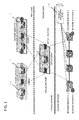
- the network configuration management section allows a first user to manage the network of the first layer using the network configuration information of the first layer and that also allows a second user to manage the network of the second layer using at least the network configuration information of the second layer (see Fig.1 ). It is noted that the content for processing, accepted by the network configuration management section (22 of Fig.2 ) from the user, is forwarded to a control device, not shown, for controlling the individual switches.
- a user to whom a network identifier: 1 is allocated and another user to whom a network identifier: 2 is allocated share a virtual network constituted from one and the same physical network.
- the network management device 20 configures a virtual node 11, using a plurality of physical switches, and places the so configured virtual node in a network of a second layer.
- the network of the second layer is represented by a symbol.
- the second layer is managed by a third user who manages the network of the second layer.
- a virtual network is split into a plurality of layers and that, in an upper layer, an area whose low level configuration is desired to be concealed is represented by a symbol.
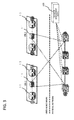
- Fig.3 is a schematic view which may be referenced in understanding the first exemplary embodiment.
- VN1 is an acronym of VXLAN Network Identifier
- VXLAN an acronym of Virtual Extensible Local Area Network.
- the virtual node 11 of the virtual network of Fig.3 is placed in a second layer with virtual end points, as shown in Fig.4 , and network slicing is made by VXLAN in the first layer.
- the above mentioned virtual node of the network of the second layer is represented by a symbol 'virtual tunnel' that has interfaces mapped to the virtual end points of the second layer.
- flow control that takes the VNIs into consideration may be exercised in the second layer as well.
- a user or a user group in the second layer may be identified by imparting an identifier for the second layer to e.g., a header of a user packet.
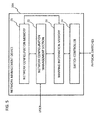
- Fig.5 shows a configuration of a network management device 20A of the first exemplary embodiment of the present invention.
- the network management device of the subject exemplary embodiment differs from the network management device shown in Fig.2 in such points that there are provided a mapping information memory 23 that stores the relation of correspondence between the user identifiers of the first and second layers and a switch controller 24 that causes the switch(es) on the physical network to perform the processing of writing the user identifier in a packet header based on this relation of correspondence.
- Fig.6 shows an example storage location of the identifier for the second layer.
- an identifier for the second layer is stored at a preset location of an additional header of VXLAN etc. This enables flow identification making use of an identifier for the second layer as well.
- Fig.7 shows another example of the storage location for the identifier for the second layer.
- the example of Fig.7 is such a one in which the identifier for the second layer is stored at a preset location of a header of an upper layer protocol on an inner side of the additional header of VXLAN etc.
- FIG.8 illustrates a physical configuration of a virtual network of the second exemplary embodiment of the present invention. Since the subject exemplary embodiment may be implemented by a configuration similar to that of the first exemplary embodiment, the following description is centered about the points of difference from the above described first exemplary embodiment.
- Fig.8 shows a configuration in which switches #1, #2 controlled to perform slicing by a VSID (Virtual Subset iDentifier) in accordance with NVGRE (Network Virtualization using Generic Routing Encapsulation) are connected via a gateway GW to switches #3, #4 that are outside the NVGRE.
- VSID Virtual Subset iDentifier
- NVGRE Network Virtualization using Generic Routing Encapsulation
- hypervisor hosts #1, #2 implemented by a hypervisor type server virtualization application.
- b1 through to b4 denote boundaries of domains configured by a controller.
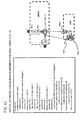
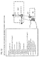
- Fig.9 shows an example of the configuration information of the domains and the boundaries in the network configuration of Fig.8 .
- five domains and the boundaries b1 through to b4 lying at border lines thereof are defined by the combinations of switches and ports, as seen from Fig.8 .
- Fig.10 shows an example of the configuration information of a virtual network of the second layer composed of the switches #1, #2 of Fig.8 .
- a virtual bridge vbr1 constituted by the switches #1, #2, interfaces of the virtual bridge and virtual links defined by tunnel end points (vteps) are defined.
- the virtual links are mapped to the boundaries b1 through to b3 of Fig.8 and '10' is donated to each of the links as vlan-id.
- Fig.11 shows an example of the configuration information of the first layer in which the virtual network of the second layer of Fig.10 is placed as a virtual tunnel.
- the virtual network shown in Fig.10
- the virtual network is represented by a virtual tunnel vtunne11 having the VSID: 10 and is connected to virtual bridges vbr1, vbr2 of the first layer.
- the virtual tunnel vtunne11 has its interfaces mapped to virtual tunnel end points vtep1, vtep3 of Fig.10 .
- end points 1, 4 connecting to interfaces of virtual bridges vbr1, vbr3 of the network of the first layer, are mapped to a port of the hypervisor host #1 and to a port of the switch #4.
- Fig.12 shows another example of the configuration information of the first layer in which the virtual network of the second layer shown in Fig.10 is placed as a virtual tunnel.
- the virtual network shown in Fig.10
- the virtual network is represented by a virtual tunnel vtunne11 having a VSDI: 20, and is connected to the virtual bridges vbr1, vbr2 of the first layer.
- the virtual tunnel vtunne11 has its interfaces mapped to virtual tunnel end points vtep2, vtep3 of Fig.10 .
- end points 2, 3 connecting to interfaces of the virtual bridges vbr1, vbr3 of the network of the first layer, are mapped to a port of the hypervisor host #2 and to a port of the switch #3.
- the physical network is ultimately expanded, as shown in Fig.13 , into a virtual network having two layers whose corresponding elements are mapped.
- the user with the VSID: 1 is able to set and manage a network on the basis of a virtual network vtn1-A that is simplified by the virtual tunnel.
- the user with the VSID: 2 is able to set and manage a network on the basis of a virtual network vtn1-B that is simplified by the virtual tunnel.
- flow control etc. by VLAN ID may be exercised based on the virtual network vtn1 of the second layer.
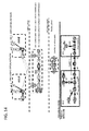
- FIG.14 illustrates a configuration of a virtual network of the third exemplary embodiment of the present invention. Since the subject exemplary embodiment may be implemented by a configuration and the manner of configuration about similar to those of the second exemplary embodiment, the following description is centered about the points of difference from the above described second exemplary embodiment.
- a physical network interconnects two data centers via EoMPLS (Ethernet (registered trademark) over MPLS).
- the EoMPLS (Ethernet (registered trademark) over MPLS) part is represented, in a virtual network, by a network of a third layer including a virtual switch that exercises control by an MPLS label.
- the network of the third layer is represented by a virtual tunnel, and a virtual bridge or a virtual router is arranged from one domain to another.
- the network of the second layer is represented by a virtual tunnel and a virtual router is arranged from one domain to another.
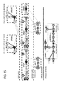
- FIG.15 illustrates a configuration of a virtual network of the fourth exemplary embodiment of the present invention. Since the subject exemplary embodiment may be implemented by the configuration and the manner of configuration similar to those of the second and third exemplary embodiments, the following description is centered about the points of difference from these exemplary embodiments.
- slicing is performed in the first to third layers using a physical network including an EoMPLS network and a legacy switch.
- the virtual network, sliced in a lower layer, is represented as a virtual tunnel in an upper layer, and relevant ones of the virtual tunnel end points and interfaces are mapped one to another.
- the present invention can be applied to such a case where slicing is made in a plurality of layers of, for example, MPLS, VLAN or NVGRE, so that, as in the above described exemplary embodiments, it is possible to simplify the configuration of the virtual network operated by the end user.
- VXLAN or NVGRE in the upper layer.
- VXLAN or NVGRE in the upper layer.
- VLAN or MPLS is to be used in the lower layer as well.
- the network management device includes the network configuration memory and the network configuration management section.
- these may be arranged as separate devices, or may be implemented as respective functions of a control device controlling the physical switches.
- the communication system further comprising a mapping information memory that stores a relation of correspondence between an identifier for identifying a user in the first layer and another identifier for identifying a user in the second layer, wherein the both identifiers are used so as to perform management so that flow control can be exercised in both the first and second layers.
- the communication system further comprising a switch controller that causes a switch on a path to perform the processing of writing the identifier for identifying the user in the second layer in a header based on the identifier that identifies the user in the first layer and that is contained in a user packet.
- the identifier for identifying the user in the second layer is stored in a preset area of a header that stores the identifier of the first layer.
- the identifier for identifying the user in the second layer is stored in a preset area of a second header lying on an inner side of the header storing the identifier of the first layer.
- the virtual network management apparatus further comprising:
- the virtual network management apparatus further comprising a switch controller that causes a switch on a path to perform a processing of writing the identifier for identifying the user in the second layer in a header based on the identifier that identifies the user in the first layer and that is contained in a user packet.
- the mode 7 can be expanded to the modes 4 to 6, as in the above mode 1
- the modes 10, 11 can be expanded to the modes 2 to 6, as in the above mode 1.
- Patent Literatures as well as non-Patent Literatures are to be incorporated herein by reference.
- the exemplary embodiments or Examples may be modified or adjusted within the concept of the total disclosures of the present invention, inclusive of claims, based on the fundamental technical concept of the invention.
- a wide variety of combinations or selections of elements herein disclosed may be made within the context of the claims of the present invention. That is, the present invention may include a wide variety of changes or corrections that may occur to those skilled in the art in accordance with the total disclosures inclusive of the claims and the drawings as well as the technical concept of the invention.
Landscapes
- Engineering & Computer Science (AREA)
- Computer Networks & Wireless Communication (AREA)
- Signal Processing (AREA)
- Computer Security & Cryptography (AREA)
- Computer Hardware Design (AREA)
- Computing Systems (AREA)
- General Engineering & Computer Science (AREA)
- Data Exchanges In Wide-Area Networks (AREA)
Applications Claiming Priority (2)
| Application Number | Priority Date | Filing Date | Title |
|---|---|---|---|
| JP2012223123 | 2012-10-05 | ||
| PCT/JP2013/077040 WO2014054768A1 (ja) | 2012-10-05 | 2013-10-04 | 通信システム、仮想ネットワーク管理装置、仮想ネットワークの管理方法及びプログラム |
Publications (3)
| Publication Number | Publication Date |
|---|---|
| EP2905926A1 true EP2905926A1 (de) | 2015-08-12 |
| EP2905926A4 EP2905926A4 (de) | 2016-06-22 |
| EP2905926B1 EP2905926B1 (de) | 2017-11-22 |
Family
ID=50435087
Family Applications (1)
| Application Number | Title | Priority Date | Filing Date |
|---|---|---|---|
| EP13843992.2A Active EP2905926B1 (de) | 2012-10-05 | 2013-10-04 | Kommunikationssystem, vorrichtung zur verwaltung virtueller netzwerke, verfahren zur verwaltung virtueller netzwerke und programm |
Country Status (5)
| Country | Link |
|---|---|
| US (1) | US9794111B2 (de) |
| EP (1) | EP2905926B1 (de) |
| JP (1) | JP6248938B2 (de) |
| CN (1) | CN104704772B (de) |
| WO (1) | WO2014054768A1 (de) |
Families Citing this family (12)
| Publication number | Priority date | Publication date | Assignee | Title |
|---|---|---|---|---|
| US10250443B2 (en) * | 2014-09-30 | 2019-04-02 | Nicira, Inc. | Using physical location to modify behavior of a distributed virtual network element |
| ES2752765T3 (es) * | 2014-10-30 | 2020-04-06 | Nec Corp | Dispositivo de control de red y método de gestión de información de red |
| JP6500489B2 (ja) * | 2015-02-24 | 2019-04-17 | 日本電気株式会社 | 表示システム、表示方法、表示プログラムおよび仮想システム |
| US9775045B2 (en) * | 2015-09-11 | 2017-09-26 | Intel IP Corporation | Slicing architecture for wireless communication |
| CN107318113B (zh) * | 2016-04-27 | 2021-09-21 | 华为技术有限公司 | 网络切片处理方法和装置 |
| KR102499705B1 (ko) * | 2016-06-10 | 2023-02-14 | 한국전자통신연구원 | 네트워크 서비스 검출 방법 및 이를 위한 장치 |
| US10681131B2 (en) | 2016-08-29 | 2020-06-09 | Vmware, Inc. | Source network address translation detection and dynamic tunnel creation |
| US10225103B2 (en) | 2016-08-29 | 2019-03-05 | Vmware, Inc. | Method and system for selecting tunnels to send network traffic through |
| US10164829B1 (en) * | 2017-03-20 | 2018-12-25 | Barefoot Networks, Inc. | Incremental update of the data plane of a hardware forwarding element |
| JP6744345B2 (ja) * | 2018-02-20 | 2020-08-19 | 日本電信電話株式会社 | 監視装置、ネットワーク障害監視システムおよび監視方法 |
| CN110650076B (zh) * | 2018-06-26 | 2021-12-24 | 华为技术有限公司 | Vxlan的实现方法,网络设备和通信系统 |
| WO2021219233A1 (en) * | 2020-04-30 | 2021-11-04 | Telefonaktiebolaget Lm Ericsson (Publ) | Network management |
Family Cites Families (13)
| Publication number | Priority date | Publication date | Assignee | Title |
|---|---|---|---|---|
| JPH06326706A (ja) * | 1993-05-11 | 1994-11-25 | Sumitomo Electric Ind Ltd | 複合ネットワーク管理システム |
| JP3609562B2 (ja) | 1996-11-15 | 2005-01-12 | 株式会社日立製作所 | ネットワーク管理システム |
| JP3617770B2 (ja) * | 1998-05-29 | 2005-02-09 | 株式会社日立製作所 | ネットワーク管理システム及びネットワーク管理方式 |
| US20060098649A1 (en) * | 2004-11-10 | 2006-05-11 | Trusted Network Technologies, Inc. | System, apparatuses, methods, and computer-readable media for determining security realm identity before permitting network connection |
| JP4068492B2 (ja) * | 2003-04-01 | 2008-03-26 | 富士通株式会社 | ネットワークレイヤ連携プログラムおよびネットワークレイヤ連携装置 |
| JP4650607B2 (ja) | 2004-01-14 | 2011-03-16 | 日本電気株式会社 | ネットワーク管理システム、ネットワーク管理方法及びネットワーク管理用プログラム |
| JP4606249B2 (ja) | 2005-05-18 | 2011-01-05 | 富士通株式会社 | 情報処理方法及びルータ |
| CN101217398A (zh) | 2007-12-28 | 2008-07-09 | 华为技术有限公司 | 分布式网管采集系统、实现方法及相关设备 |
| CN102473111B (zh) | 2009-07-31 | 2016-08-03 | 日本电气株式会社 | 控制服务器、服务提供系统以及虚拟基础结构的提供方法 |
| WO2011114389A1 (ja) * | 2010-03-19 | 2011-09-22 | 富士通株式会社 | 資産管理装置、資産管理方法および資産管理プログラム |
| JP5710928B2 (ja) * | 2010-10-07 | 2015-04-30 | 株式会社日立製作所 | ネットワークシステム、仮想ネットワーク管理方法及びルータ |
| CN103460666B (zh) * | 2011-03-29 | 2017-02-15 | 日本电气株式会社 | 网络系统和vlan标签数据获取方法 |
| CN102263667B (zh) * | 2011-08-24 | 2015-09-23 | 迈普通信技术股份有限公司 | 网络管理系统以及网络管理处理方法 |
-
2013
- 2013-10-04 CN CN201380052113.XA patent/CN104704772B/zh active Active
- 2013-10-04 WO PCT/JP2013/077040 patent/WO2014054768A1/ja not_active Ceased
- 2013-10-04 JP JP2014539834A patent/JP6248938B2/ja not_active Expired - Fee Related
- 2013-10-04 US US14/433,015 patent/US9794111B2/en active Active
- 2013-10-04 EP EP13843992.2A patent/EP2905926B1/de active Active
Non-Patent Citations (1)
| Title |
|---|
| See references of WO2014054768A1 * |
Also Published As
| Publication number | Publication date |
|---|---|
| EP2905926B1 (de) | 2017-11-22 |
| EP2905926A4 (de) | 2016-06-22 |
| JPWO2014054768A1 (ja) | 2016-08-25 |
| CN104704772A (zh) | 2015-06-10 |
| US20150249565A1 (en) | 2015-09-03 |
| CN104704772B (zh) | 2018-06-15 |
| JP6248938B2 (ja) | 2017-12-20 |
| WO2014054768A1 (ja) | 2014-04-10 |
| US9794111B2 (en) | 2017-10-17 |
Similar Documents
| Publication | Publication Date | Title |
|---|---|---|
| US9794111B2 (en) | Communication system, virtual network management apparatus, virtual network management method and program | |
| US11804987B2 (en) | Flow generation from second level controller to first level controller to managed switching element | |
| US10237377B2 (en) | Packet rewriting apparatus, control apparatus, communication system, packet transmission method and program | |
| CN107925589B (zh) | 处理进入逻辑覆盖网络的远程设备数据消息的方法和介质 | |
| KR101460848B1 (ko) | 가상 스위치를 구현 및 관리하는 방법 및 장치 | |
| US10320671B2 (en) | Extension of logical networks across layer 3 virtual private networks | |
| EP2942912A1 (de) | Steuerungsvorrichtung, kommunikationssystem, tunnelendpunktsteuerungsverfahren und programm | |
| EP2947826A1 (de) | Steuerungsvorrichtung, kommunikationsvorrichtung, kommunikationssystem, schaltsteuerungsvorrichtung und programm | |
| KR101527377B1 (ko) | Sdn 기반의 서비스 체이닝 시스템 | |
| US10567222B2 (en) | Recommending configurations for client networking environment based on aggregated cloud managed information | |
| Efraim et al. | Using SR-IOV offloads with Open-vSwitch and similar applications | |
| Filter-Based | I2RS Working Group L. Dunbar Internet-Draft S. Hares Intended status: Informational Huawei Expires: September 25, 2015 J. Tantsura Ericsson |
Legal Events
| Date | Code | Title | Description |
|---|---|---|---|
| PUAI | Public reference made under article 153(3) epc to a published international application that has entered the european phase |
Free format text: ORIGINAL CODE: 0009012 |
|
| 17P | Request for examination filed |
Effective date: 20150224 |
|
| AK | Designated contracting states |
Kind code of ref document: A1 Designated state(s): AL AT BE BG CH CY CZ DE DK EE ES FI FR GB GR HR HU IE IS IT LI LT LU LV MC MK MT NL NO PL PT RO RS SE SI SK SM TR |
|
| AX | Request for extension of the european patent |
Extension state: BA ME |
|
| DAX | Request for extension of the european patent (deleted) | ||
| RA4 | Supplementary search report drawn up and despatched (corrected) |
Effective date: 20160520 |
|
| RIC1 | Information provided on ipc code assigned before grant |
Ipc: H04L 12/801 20130101ALI20160513BHEP Ipc: H04L 12/24 20060101AFI20160513BHEP Ipc: H04L 12/70 20130101ALI20160513BHEP Ipc: H04L 29/06 20060101ALI20160513BHEP Ipc: H04L 12/721 20130101ALI20160513BHEP |
|
| RIC1 | Information provided on ipc code assigned before grant |
Ipc: H04L 12/70 20130101ALI20170503BHEP Ipc: H04L 29/06 20060101ALI20170503BHEP Ipc: H04L 12/801 20130101ALI20170503BHEP Ipc: H04L 12/721 20130101ALI20170503BHEP Ipc: H04L 12/24 20060101AFI20170503BHEP |
|
| GRAP | Despatch of communication of intention to grant a patent |
Free format text: ORIGINAL CODE: EPIDOSNIGR1 |
|
| INTG | Intention to grant announced |
Effective date: 20170614 |
|
| GRAS | Grant fee paid |
Free format text: ORIGINAL CODE: EPIDOSNIGR3 |
|
| GRAA | (expected) grant |
Free format text: ORIGINAL CODE: 0009210 |
|
| AK | Designated contracting states |
Kind code of ref document: B1 Designated state(s): AL AT BE BG CH CY CZ DE DK EE ES FI FR GB GR HR HU IE IS IT LI LT LU LV MC MK MT NL NO PL PT RO RS SE SI SK SM TR |
|
| REG | Reference to a national code |
Ref country code: GB Ref legal event code: FG4D |
|
| REG | Reference to a national code |
Ref country code: CH Ref legal event code: EP |
|
| REG | Reference to a national code |
Ref country code: IE Ref legal event code: FG4D |
|
| REG | Reference to a national code |
Ref country code: AT Ref legal event code: REF Ref document number: 949341 Country of ref document: AT Kind code of ref document: T Effective date: 20171215 |
|
| REG | Reference to a national code |
Ref country code: DE Ref legal event code: R096 Ref document number: 602013029936 Country of ref document: DE |
|
| REG | Reference to a national code |
Ref country code: NL Ref legal event code: MP Effective date: 20171122 |
|
| REG | Reference to a national code |
Ref country code: LT Ref legal event code: MG4D |
|
| REG | Reference to a national code |
Ref country code: AT Ref legal event code: MK05 Ref document number: 949341 Country of ref document: AT Kind code of ref document: T Effective date: 20171122 |
|
| PG25 | Lapsed in a contracting state [announced via postgrant information from national office to epo] |
Ref country code: NL Free format text: LAPSE BECAUSE OF FAILURE TO SUBMIT A TRANSLATION OF THE DESCRIPTION OR TO PAY THE FEE WITHIN THE PRESCRIBED TIME-LIMIT Effective date: 20171122 Ref country code: LT Free format text: LAPSE BECAUSE OF FAILURE TO SUBMIT A TRANSLATION OF THE DESCRIPTION OR TO PAY THE FEE WITHIN THE PRESCRIBED TIME-LIMIT Effective date: 20171122 Ref country code: ES Free format text: LAPSE BECAUSE OF FAILURE TO SUBMIT A TRANSLATION OF THE DESCRIPTION OR TO PAY THE FEE WITHIN THE PRESCRIBED TIME-LIMIT Effective date: 20171122 Ref country code: SE Free format text: LAPSE BECAUSE OF FAILURE TO SUBMIT A TRANSLATION OF THE DESCRIPTION OR TO PAY THE FEE WITHIN THE PRESCRIBED TIME-LIMIT Effective date: 20171122 Ref country code: FI Free format text: LAPSE BECAUSE OF FAILURE TO SUBMIT A TRANSLATION OF THE DESCRIPTION OR TO PAY THE FEE WITHIN THE PRESCRIBED TIME-LIMIT Effective date: 20171122 Ref country code: NO Free format text: LAPSE BECAUSE OF FAILURE TO SUBMIT A TRANSLATION OF THE DESCRIPTION OR TO PAY THE FEE WITHIN THE PRESCRIBED TIME-LIMIT Effective date: 20180222 |
|
| PG25 | Lapsed in a contracting state [announced via postgrant information from national office to epo] |
Ref country code: GR Free format text: LAPSE BECAUSE OF FAILURE TO SUBMIT A TRANSLATION OF THE DESCRIPTION OR TO PAY THE FEE WITHIN THE PRESCRIBED TIME-LIMIT Effective date: 20180223 Ref country code: BG Free format text: LAPSE BECAUSE OF FAILURE TO SUBMIT A TRANSLATION OF THE DESCRIPTION OR TO PAY THE FEE WITHIN THE PRESCRIBED TIME-LIMIT Effective date: 20180222 Ref country code: AT Free format text: LAPSE BECAUSE OF FAILURE TO SUBMIT A TRANSLATION OF THE DESCRIPTION OR TO PAY THE FEE WITHIN THE PRESCRIBED TIME-LIMIT Effective date: 20171122 Ref country code: LV Free format text: LAPSE BECAUSE OF FAILURE TO SUBMIT A TRANSLATION OF THE DESCRIPTION OR TO PAY THE FEE WITHIN THE PRESCRIBED TIME-LIMIT Effective date: 20171122 Ref country code: HR Free format text: LAPSE BECAUSE OF FAILURE TO SUBMIT A TRANSLATION OF THE DESCRIPTION OR TO PAY THE FEE WITHIN THE PRESCRIBED TIME-LIMIT Effective date: 20171122 Ref country code: RS Free format text: LAPSE BECAUSE OF FAILURE TO SUBMIT A TRANSLATION OF THE DESCRIPTION OR TO PAY THE FEE WITHIN THE PRESCRIBED TIME-LIMIT Effective date: 20171122 |
|
| PG25 | Lapsed in a contracting state [announced via postgrant information from national office to epo] |
Ref country code: DK Free format text: LAPSE BECAUSE OF FAILURE TO SUBMIT A TRANSLATION OF THE DESCRIPTION OR TO PAY THE FEE WITHIN THE PRESCRIBED TIME-LIMIT Effective date: 20171122 Ref country code: SK Free format text: LAPSE BECAUSE OF FAILURE TO SUBMIT A TRANSLATION OF THE DESCRIPTION OR TO PAY THE FEE WITHIN THE PRESCRIBED TIME-LIMIT Effective date: 20171122 Ref country code: EE Free format text: LAPSE BECAUSE OF FAILURE TO SUBMIT A TRANSLATION OF THE DESCRIPTION OR TO PAY THE FEE WITHIN THE PRESCRIBED TIME-LIMIT Effective date: 20171122 Ref country code: CY Free format text: LAPSE BECAUSE OF FAILURE TO SUBMIT A TRANSLATION OF THE DESCRIPTION OR TO PAY THE FEE WITHIN THE PRESCRIBED TIME-LIMIT Effective date: 20171122 Ref country code: CZ Free format text: LAPSE BECAUSE OF FAILURE TO SUBMIT A TRANSLATION OF THE DESCRIPTION OR TO PAY THE FEE WITHIN THE PRESCRIBED TIME-LIMIT Effective date: 20171122 |
|
| REG | Reference to a national code |
Ref country code: DE Ref legal event code: R097 Ref document number: 602013029936 Country of ref document: DE |
|
| PG25 | Lapsed in a contracting state [announced via postgrant information from national office to epo] |
Ref country code: PL Free format text: LAPSE BECAUSE OF FAILURE TO SUBMIT A TRANSLATION OF THE DESCRIPTION OR TO PAY THE FEE WITHIN THE PRESCRIBED TIME-LIMIT Effective date: 20171122 Ref country code: IT Free format text: LAPSE BECAUSE OF FAILURE TO SUBMIT A TRANSLATION OF THE DESCRIPTION OR TO PAY THE FEE WITHIN THE PRESCRIBED TIME-LIMIT Effective date: 20171122 Ref country code: SM Free format text: LAPSE BECAUSE OF FAILURE TO SUBMIT A TRANSLATION OF THE DESCRIPTION OR TO PAY THE FEE WITHIN THE PRESCRIBED TIME-LIMIT Effective date: 20171122 Ref country code: RO Free format text: LAPSE BECAUSE OF FAILURE TO SUBMIT A TRANSLATION OF THE DESCRIPTION OR TO PAY THE FEE WITHIN THE PRESCRIBED TIME-LIMIT Effective date: 20171122 |
|
| REG | Reference to a national code |
Ref country code: FR Ref legal event code: PLFP Year of fee payment: 6 |
|
| PLBE | No opposition filed within time limit |
Free format text: ORIGINAL CODE: 0009261 |
|
| STAA | Information on the status of an ep patent application or granted ep patent |
Free format text: STATUS: NO OPPOSITION FILED WITHIN TIME LIMIT |
|
| 26N | No opposition filed |
Effective date: 20180823 |
|
| PG25 | Lapsed in a contracting state [announced via postgrant information from national office to epo] |
Ref country code: SI Free format text: LAPSE BECAUSE OF FAILURE TO SUBMIT A TRANSLATION OF THE DESCRIPTION OR TO PAY THE FEE WITHIN THE PRESCRIBED TIME-LIMIT Effective date: 20171122 |
|
| REG | Reference to a national code |
Ref country code: CH Ref legal event code: PL |
|
| REG | Reference to a national code |
Ref country code: BE Ref legal event code: MM Effective date: 20181031 |
|
| PG25 | Lapsed in a contracting state [announced via postgrant information from national office to epo] |
Ref country code: LU Free format text: LAPSE BECAUSE OF NON-PAYMENT OF DUE FEES Effective date: 20181004 Ref country code: MC Free format text: LAPSE BECAUSE OF FAILURE TO SUBMIT A TRANSLATION OF THE DESCRIPTION OR TO PAY THE FEE WITHIN THE PRESCRIBED TIME-LIMIT Effective date: 20171122 |
|
| REG | Reference to a national code |
Ref country code: IE Ref legal event code: MM4A |
|
| PG25 | Lapsed in a contracting state [announced via postgrant information from national office to epo] |
Ref country code: LI Free format text: LAPSE BECAUSE OF NON-PAYMENT OF DUE FEES Effective date: 20181031 Ref country code: BE Free format text: LAPSE BECAUSE OF NON-PAYMENT OF DUE FEES Effective date: 20181031 Ref country code: CH Free format text: LAPSE BECAUSE OF NON-PAYMENT OF DUE FEES Effective date: 20181031 |
|
| PG25 | Lapsed in a contracting state [announced via postgrant information from national office to epo] |
Ref country code: IE Free format text: LAPSE BECAUSE OF NON-PAYMENT OF DUE FEES Effective date: 20181004 |
|
| PG25 | Lapsed in a contracting state [announced via postgrant information from national office to epo] |
Ref country code: MT Free format text: LAPSE BECAUSE OF NON-PAYMENT OF DUE FEES Effective date: 20181004 |
|
| PG25 | Lapsed in a contracting state [announced via postgrant information from national office to epo] |
Ref country code: TR Free format text: LAPSE BECAUSE OF FAILURE TO SUBMIT A TRANSLATION OF THE DESCRIPTION OR TO PAY THE FEE WITHIN THE PRESCRIBED TIME-LIMIT Effective date: 20171122 |
|
| PG25 | Lapsed in a contracting state [announced via postgrant information from national office to epo] |
Ref country code: PT Free format text: LAPSE BECAUSE OF FAILURE TO SUBMIT A TRANSLATION OF THE DESCRIPTION OR TO PAY THE FEE WITHIN THE PRESCRIBED TIME-LIMIT Effective date: 20171122 |
|
| PG25 | Lapsed in a contracting state [announced via postgrant information from national office to epo] |
Ref country code: MK Free format text: LAPSE BECAUSE OF NON-PAYMENT OF DUE FEES Effective date: 20171122 Ref country code: HU Free format text: LAPSE BECAUSE OF FAILURE TO SUBMIT A TRANSLATION OF THE DESCRIPTION OR TO PAY THE FEE WITHIN THE PRESCRIBED TIME-LIMIT; INVALID AB INITIO Effective date: 20131004 |
|
| PG25 | Lapsed in a contracting state [announced via postgrant information from national office to epo] |
Ref country code: AL Free format text: LAPSE BECAUSE OF FAILURE TO SUBMIT A TRANSLATION OF THE DESCRIPTION OR TO PAY THE FEE WITHIN THE PRESCRIBED TIME-LIMIT Effective date: 20171122 Ref country code: IS Free format text: LAPSE BECAUSE OF FAILURE TO SUBMIT A TRANSLATION OF THE DESCRIPTION OR TO PAY THE FEE WITHIN THE PRESCRIBED TIME-LIMIT Effective date: 20180322 |
|
| REG | Reference to a national code |
Ref country code: DE Ref legal event code: R079 Ref document number: 602013029936 Country of ref document: DE Free format text: PREVIOUS MAIN CLASS: H04L0012240000 Ipc: H04L0041000000 |
|
| REG | Reference to a national code |
Ref country code: DE Ref legal event code: R081 Ref document number: 602013029936 Country of ref document: DE Owner name: NEC ASIA PACIFIC PTE LTD., SG Free format text: FORMER OWNER: NEC CORPORATION, TOKYO, JP |
|
| REG | Reference to a national code |
Ref country code: GB Ref legal event code: 732E Free format text: REGISTERED BETWEEN 20240321 AND 20240327 |
|
| PGFP | Annual fee paid to national office [announced via postgrant information from national office to epo] |
Ref country code: DE Payment date: 20251031 Year of fee payment: 13 |
|
| PGFP | Annual fee paid to national office [announced via postgrant information from national office to epo] |
Ref country code: GB Payment date: 20251029 Year of fee payment: 13 |
|
| PGFP | Annual fee paid to national office [announced via postgrant information from national office to epo] |
Ref country code: FR Payment date: 20251027 Year of fee payment: 13 |