EP2906494B1 - Pont roulant, notamment sous forme de pont ou de portique, comportant au moins une poutre - Google Patents
Pont roulant, notamment sous forme de pont ou de portique, comportant au moins une poutre Download PDFInfo
- Publication number
- EP2906494B1 EP2906494B1 EP13773732.6A EP13773732A EP2906494B1 EP 2906494 B1 EP2906494 B1 EP 2906494B1 EP 13773732 A EP13773732 A EP 13773732A EP 2906494 B1 EP2906494 B1 EP 2906494B1
- Authority
- EP
- European Patent Office
- Prior art keywords
- crane
- struts
- chord
- recess
- strut
- Prior art date
- Legal status (The legal status is an assumption and is not a legal conclusion. Google has not performed a legal analysis and makes no representation as to the accuracy of the status listed.)
- Active
Links
Images



Classifications
-
- B—PERFORMING OPERATIONS; TRANSPORTING
- B66—HOISTING; LIFTING; HAULING
- B66C—CRANES; LOAD-ENGAGING ELEMENTS OR DEVICES FOR CRANES, CAPSTANS, WINCHES, OR TACKLES
- B66C6/00—Girders, or track-supporting structures, specially adapted for cranes
-
- B—PERFORMING OPERATIONS; TRANSPORTING
- B66—HOISTING; LIFTING; HAULING
- B66C—CRANES; LOAD-ENGAGING ELEMENTS OR DEVICES FOR CRANES, CAPSTANS, WINCHES, OR TACKLES
- B66C19/00—Cranes comprising trolleys or crabs running on fixed or movable bridges or gantries
Definitions
- the invention relates to a crane, in particular a bridge crane or gantry crane, comprising at least one crane girder which extends horizontally in a longitudinal direction and is designed as truss girder and which comprises a top girder and a bottom girder connecting flat-shaped struts and on which a crane trolley can be moved with a hoist.
- a crane in particular a bridge crane or gantry crane, comprising at least one crane girder which extends horizontally in a longitudinal direction and is designed as truss girder and which comprises a top girder and a bottom girder connecting flat-shaped struts and on which a crane trolley can be moved with a hoist.
- German patent DE 260030 is a so-called two-gantry gantry crane with two horizontal crane girders and two vertical support beams known to form a portal frame of the gantry crane.
- the crane girders run parallel and at a distance from each other.
- a chassis is arranged in each case, via which the gantry crane is movable in a direction transverse to the longitudinal direction of the crane girder travel direction.
- On and along the crane girder is a trolley with a cable travels.
- a load-receiving means of the cable crane arranged on the cable between both crane girders is lowered or raised.
- the crane girders are designed as truss girders and each comprise a top chord and a bottom chord which are each aligned horizontally and parallel to one another.
- the upper and lower chords of the two crane girders are connected by vertically extending rod-shaped posts and diagonally extending rod-shaped struts.
- the two crane girders are connected at their ends via cross bars and struts together to form a frame.
- rod-shaped posts and struts are provided between the upper and lower girders in the manner of a truss, each connecting an upper girth to the lower girder arranged underneath.
- the German Utility Model DE 1 971 794 U describes a two-girder bridge crane whose two horizontal crane girders are connected to each other via arranged at their respective ends head carrier and together in a direction transverse to the longitudinal direction of the crane girder travel direction.
- Both crane girders are similarly designed as truss girders and each comprise plate-shaped upper girths, bar-shaped lower girders and rod-shaped posts.
- the German patent DE 10 95 486 B discloses a trained as truss crane girder, the top and bottom chord connecting struts are formed by rod-shaped T-profiles.
- the rod-shaped struts have at their ends recessed flanges, with which they abut the abutting upper flange, while the webs rest on the upper flange.
- EP 0 928 769 A1 is designed as a truss crane carrier described on the upper flange and lower flange angle-shaped struts lie with an L-shaped cross-section.
- the L-shaped cross-section of the angle-shaped struts is formed by a main surface extending in the longitudinal direction of the crane girder and an adjoining side surface bent by 90 degrees.
- the secondary surface has a recess arranged in the region of the upper belt.
- the US patent US Pat. No. 7,503,460 B1 discloses a trained as truss crane girder with composed of two strut profiles rod-shaped struts.
- the strut profiles are hereby spaced apart by spacers. Between the ends of the strut profiles a plate connected to a top flange or a plate connected to a bottom flange is respectively pushed and welded.
- the CN 202 465 064 U discloses composite trusses of a truss beam, each comprising a pair of spaced-apart U-profiles.
- the U-profiles are fastened on both sides with their ends to a plate-shaped web of the lower belt, which is arranged between the ends of each pair of U-profiles.
- the object of the invention is to provide a crane, in particular a bridge crane or gantry crane, with at least one improved crane girder.
- a crane in particular a bridge crane or gantry crane, comprising at least one crane girder extending horizontally in a longitudinal direction and designed as a truss girder, comprising struts interconnecting a top girth and a bottom girder and forming a flat-shaped strut and on which a crane trolley can be moved with a hoist
- the at least one crane girder is advantageously improved in that the struts are of planar design, each have a main surface extending transversely to the longitudinal direction of the crane girder, and at least one recess is provided on a first or second strut end of the struts in the main surface the lower chord or upper chord rests against the main surface.
- struts in general those elements of a truss structure, which have an oblique or diagonal course.
- the struts of a truss structure differ from the elements, which run exclusively vertically and are referred to as posts.
- the improved crane girders are distinguished by the fact that the manufacturing outlay can be reduced, since corresponding recesses can be produced particularly easily, for example by laser cutting, in the case of struts or posts made of sheet steel.
- a reduction in the variety of parts and a concomitant substantial ease of assembly is achieved by a kind of self-alignment or adjustment of the struts is realized to the lower flange or upper flange by the recesses provided in the struts.
- the particularly simple adjustment of the struts with respect to the lower chord or upper chord is achieved by inserting or inserting the lower chord or upper chord in the recess of the strut or plugging the strut on the lower chord or upper chord, whereby they interlock and are brought into contact with each other.
- the relative position of the lower flange or upper flange to the struts is thereby defined in a simple manner in translational terms.
- the sheet-like struts or surface struts preferably absorb forces in the direction of their longitudinal axis and thus in the plane of extent of their planar main surface.
- Such surface elements or surface structures are referred to in the technical mechanics as discs, whereas perpendicular to their plane of extent or main surface loaded surface elements are referred to as plates.
- Discs and thus also the surface struts according to the invention differ, for example, from bars or rod-shaped posts and struts in that their thickness dimensions are substantially smaller than the length and width dimensions determining the areal extent of the pane. Accordingly, sheet-like struts can also be referred to as surface struts or disc struts.
- the crane girders produced with sheet-like struts as lattice girders have due to the omission of non-static required sheet metal areas and an associated saving of material, a significantly reduced weight and at the same time an optimized load capacity.
- each recess is arranged in the main surface of the struts, also a simple production is possible.
- the recesses can already be made when cutting the sheet metal profile.
- the struts are positively positioned relative to the lower chord or the upper chord over the recess. Due to the positive connection, the alignment of the struts with respect to the lower chord or upper chord is further simplified before the final welding.
- the struts are connected via the recess with the lower flange or upper flange.
- the final assembly is simplified in that the struts are welded in the region of the recess with the lower flange or upper flange.
- the upper belt and the lower belt each comprise at least one vertical web and the web of the upper belt rests on an upper recess and the web of the lower belt on a lower recess.
- the upper belt comprises two upper belt profiles, each with a web or the lower belt two Untergurtprofile each with a web.
- a common upper recess is provided for two webs of the upper flange or a common lower recess is provided for two webs of the lower flange.
- the struts have at least one auxiliary surface bent at right angles from the main surface. As a result, in particular the Beulsteifmaschine the struts is increased.
- An effective form fit between the lower flange or upper flange and the struts or their recesses is achieved in that at least one of the recesses is slot-shaped and arranged between longitudinal sides of the respective main surface.
- the web of the lower flange or the web of the upper flange is welded to at least one longitudinal side of the corresponding recess running parallel to a longitudinal axis of the struts.
- the risk of buckling of the upper flange or the lower flange is particularly effectively reduced by the fact that the upper flange and the lower flange are connected to each other via a plurality of along the longitudinal direction of the crane girder arranged posts, wherein the posts are formed similar to the struts planar and at least one recess. This also achieves the carrying capacity of a corresponding bridge or gantry crane or its crane girder.
- FIG. 1 a shows a designed as a single-girder bridge crane first crane 1 a.
- the first crane 1 a comprises a crane girder 2 designed as a truss girder, which is aligned horizontally and extends with a length L in its longitudinal direction LR.
- first and second trolleys 7, 8 are fixed, so that in plan view is formed substantially double-T-shaped crane bridge.
- the first crane 1 a in a horizontal direction F transverse to the longitudinal direction LR of the crane girder 2 on rails not shown movable.
- the rails are usually arranged vertically with respect to a floor and can be raised for this purpose, for example via a suitable support structure or attached to opposite building walls.
- the first chassis 7 is driven by a first electric motor 7 a and the second chassis 8 by a second electric motor 8 a.
- a trolley 9 is suspended with a trained as a cable hoist, which is not shown on bogies transverse to the direction of travel F of the first crane 1a and along the longitudinal direction LR of the crane girder 2 movable.
- the trolley 9 is movable along and on laterally protruding running surfaces 4c of a lower flange 4 of the crane girder 2.
- the first crane 1a also comprises a crane control 10 and a suspension control switch 11 connected thereto, by means of which the first crane 1a or the electric motors 7a, 8a and the crane trolley 9 can be separately controlled and operated with the cable.
- the truss structure of the crane girder 2 essentially comprises a top chord 3, a bottom chord 4, diagonally extending struts 5 and vertical posts 6.
- the top chord 3 and the bottom chord 4 each extend mostly rectilinear, spaced apart and except at the opposite ends of the crane girder 2 parallel in the longitudinal direction LR of the crane girder 2 between the trolleys 7, 8.
- the upper flange 3 and the lower flange 4 are vertically spaced from each other.
- the upper flange 3 is composed of two in a horizontal plane arranged and horizontally spaced apart first and second Obergurtprofilen 3d, 3e together.
- the two upper flange profiles 3d, 3e are formed by an L or angle profile carrier, which in each case comprises a vertical web 3a and a horizontal flange 3c arranged at right angles thereto.
- the lower flange 4 is likewise composed, analogously to the upper flange 3, of two L or angle profile straps, namely a first lower flange profile 4d and a second lower flange profile 4e.
- Each lower flange profile 4d, 4e therefore comprises a horizontal flange 4f and a vertical web 4a, which are arranged correspondingly at right angles to one another.
- the lower flange 4 of the crane girder 2 of a first crane 1a designed as a single girder bridge crane is not formed by two lower girder profiles 4d, 4e but by a flat profile 4b with two vertically upstanding girders 4a.
- the flange 4f is laterally extended beyond the webs 4a addition.
- the opposite ends of the flange 4f form the running surfaces 4c.
- the lower flange 4 can also be formed by an upside-down T-profile support having a vertically upwardly pointing web 4a.
- Corresponding to the inverted T-shape of the web 4a of the T-profile carrier is connected at its lower end centrally with a horizontal flange 4f.
- the opposite ends of the flange 4f each form a running surface 4c for trolleys of the trolley 9.
- the upper flange 3 and the lower flange 4 are connected to one another via a plurality of respectively flat struts 5 and posts 6.
- the struts 5 as a sheet metal profile with a main surface 5a with a substantially formed rectangular cross-section, wherein the longitudinal sides to increase the buckling rigidity are folded over at least in a central region in the form of auxiliary surfaces 5b.
- the basic structure of the planar posts 6 corresponds - with correspondingly adapted dimensions - substantially the structure of the sheet-like struts 5.
- each of the planar posts 6 extends with a main surface 6a transverse to the longitudinal direction LR of the crane girder 2.
- the sheet-like posts 6 can also be arranged or aligned such that the auxiliary surfaces 6b point towards or away from one of the ends of the crane girder 2.
- the truss structure of the crane girder 2 is closed at the opposite ends of the upper flange 3 and the lower flange 4 via an adapter 12.
- the upper flange 3 and the lower flange 4 are connected to form a frame.
- the frame of the crane girder 2 is expanded overall from bottom to top and formed trapezoidal.
- the adapter 12 in the region of the upper flange 3 and on the side facing away from the upper flange 3 comprises a connection plate 12a to which holes 12d of one of the trolleys 7, 8 or their support is attached.
- a first strut 5 is connected to the lower girder 4 and extends in the longitudinal direction LR at a first angle ⁇ 1 inclined in the direction of the upper girth 3 and is fastened there in an upper node OK.
- the first angle of attack ⁇ 1 is in this case enclosed by the first strut 5 and a post 6 ending in the upper node OK.
- the first angle of attack ⁇ 1 is preferably in a range of 35 ° to 55 ° and is particularly preferably 45 °.
- a second strut 5 which extends obliquely below the angle of attack ⁇ 1 down to the lower flange 4.
- each strut 5 forms with a post 6 in the area of the corresponding upper node OK on the upper flange 3 an equal first angle of attack ⁇ 1.
- an even number of saddle roof-like obliquely or diagonally arranged struts 5 is always used, so that the last strut 5 ends at the lower flange 4.
- the angle of attack ⁇ 1 is determined prior to assembly, so that an even number of struts 5 each having the same length and the same angle of attack ⁇ 1 are used.
- the lower belt 4 serving as a rail and for this purpose forming the running surface 4c is reinforced against bending.
- the struts 5 are aligned within the truss structure of the crane girder 2 so that each of their main surface 5a extends transversely to the longitudinal direction LR of the crane girder 2.
- the struts 5 are arranged with their lower first strut ends 5g between the mutually facing inner sides of the webs 4a of the lower chord profiles 4d, 4e and applied and welded thereto.
- FIG. 1a not shown lower recess 5e arranged.
- the formation of the lower recesses 5e corresponds to that detailed in FIG.
- a lower flange 4 embodied as a T-bar
- the struts 5 with their lower first bar ends 5 g are pushed onto the upwardly pointing bar 4 a of the lower flange 4.
- the web 4a is received by a provided in the region of the lower first strut end 5g and substantially complementary to the web 4a lower recess 5e.
- the lower recess 5e is accordingly arranged along a longitudinal axis LA of the strut 5 and in relation to a width of the main surface 5a of the strut 5 centrally in this.
- each strut 5 lower recesses 5e are added, which except in the corner area between the longitudinal sides of the strut 5 and whose longitudinal axis LA can be arranged in the main surface 5a (see FIG. 2 ).
- the struts 5 are arranged between the two Obergurtprofilen 3d, 3e, wherein the Obergurtprofile 3d, 3e are welded to the inner sides of their webs 3a with the struts 5.
- upper recesses 5i arranged on the longitudinal sides of the upper second strut end 5h, in which abut the webs 3a.
- the horizontal flanges 3c of the upper belt profiles 3d, 3e in this case each point outwards and thus away from the struts 5.
- the planar posts 6 are arranged in the same way as the struts 5 with their lower first post end 6g and their upper second post end 6h between the webs 3a, 4a of the upper flange 3 and lower flange 4 and welded thereto.
- the posts 6 have corresponding lower recesses 6e and upper recesses 6i on the longitudinal sides of their main surfaces 6a.
- the posts 6 are pushed with their lower first post ends 6 g or a lower recess 6 e arranged therein on the web 4 a of the lower flange 4 and welded thereto.
- FIG. 1b is a designed as a two-girder bridge crane second crane 1 b shown, which comprises opposite the designed as a single-girder bridge crane first crane 1a two jib 2.
- Both crane girders 2 are over at their Adjacent adapter 12 is set to the desired length L and spaced parallel to each other.
- the trolleys 7, 8 also shown are attached via the adapter 12 at the ends of the two crane girders 2, so that seen in plan view, a frame is formed.
- the second crane 1 b comprises a crane trolley 9 with a trained as a cable hoist. However, the trolley 9 is not suspended from the lower chords 4 of the crane girder 2, but runs on upper chords 3 of the two crane girders 2.
- a running rail 13 is provided with a corresponding running surface 13a, so that the crane trolley 9 is arranged between the crane girders 2. Accordingly, the trolley 9 arranged centrally between crane girders 2 can be moved along the longitudinal direction LR of the crane girders 2 and between the two crane girders 2 and between the trolleys 7, 8.
- a load-receiving means of the trolley 9 arranged cable between both crane girders 2 can be lowered or raised.
- the truss structures of the two crane girders 2 of the second crane 1 b in turn comprise a lower flange 4 and a upper flange 3.
- the upper straps 3 and the lower straps 4 are in the same manner as in the first crane 1a according to FIG. 1a formed and accordingly composed of a first and a second upper flange 3d, 3e and lower flange 4d, 4e, wherein the upper flange 3d, 3e or lower flange 4d, 4e are formed by an L or angle-profile support.
- the lower flange 4 of the second crane 1 b may in principle instead of two Untergurtprofilen 4d, 4e be composed of a flat profile 4b or an upside-down T-profile support.
- each crane girder 2 is connected to the associated lower flange 4 via a plurality of planar struts 5 and a plurality of likewise planar-shaped and vertically aligned posts 6.
- the struts 5 and the posts 6 are identical for the two crane girders 2 of the second crane 1 b, respectively 1 a is after the first crane FIG. 1 a mirror-symmetrical with respect to their longitudinal axis LA formed.
- FIG. 1b can be seen that the struts 5 in the same way as in the FIG. 1 A shown crane girders 2 are arranged like a saddle roof.
- two adjacent struts 5 is also associated with a planar-shaped post 6 in such a way that struts 5 and the post 6 meet at a common lower node UK on the lower chords 4.
- each strut 5 forms with the associated planar pillar 6 in the region of the corresponding lower node UK at the lower chords 4 an equal second pitch angle ⁇ 2, which is like the first pitch ⁇ 1 preferably in a range of 35 ° to 55 ° and particularly preferred 45 °.
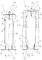
- FIG. 2 shows a cross-sectional view of one of the two crane girder 2 for a bridge crane designed as a two-girder crane.
- the basic structure of the struts 5 can be seen, which essentially corresponds to the basic structure of the also planar-shaped post 6, but this may differ in particular with regard to the dimensions.
- the remarks to the FIG. 2 also apply to the in the FIG. 1 A crane carrier 2 shown a designed as a single-carrier crane bridge crane. For the sake of simplicity, the description of the FIG.
- reference numerals 5a to 5j analogously denote the corresponding elements of the planar posts 6, which are drawn at the same locations as reference numerals 6a to 6j and listed in the list of reference numerals.
- strut 5 comprises a elongate shape having a substantially rectangular main surface 5a.
- the main surface 5a extends along the longitudinal axis LA of the strut 5 and at least in a central region over at least half the width B of the crane girder 2 transversely to the longitudinal direction LR of the crane girder 2.
- the struts 5 are preferably made by laser cutting from a steel sheet.
- the struts 5 have a lower first strut end 5g and an upper second strut end 5h. In the region of their opposing lower first and upper second strut ends 5g, 5h, two lower recesses 5c and two upper recesses 5d are provided on both longitudinal sides of the strut 5.
- the recesses 5c, 5d are round, preferably circular arc-shaped, and with regard to the welding of the struts 5 to the upper flange 3 and the lower flange 4 of the crane girder 2, the force flow through the welded-on struts 5 is optimized and the welds S or the weld outlets be relieved.
- the secondary surfaces 5b are substantially trapezoidal in shape (see also FIG. 4 ).
- the strut 5 can also have seen in an appropriate manner an at least partially L-shaped cross section in the direction of the longitudinal axis LA.
- the BeulsteifIER the struts 5 is increased.
- the secondary surfaces 5b are located outside of the webs 3a, 4a, so that only non-folded regions of the main surfaces 5a are welded to the webs 3a, 4a.
- the lower flange 4 is formed by two Untergurtprofilen 4d, 4e, with one of the FIG. 1 a deviating structure of the lower first strut ends 5g and the upper second strut ends 5h of the struts 5 results, the structure of each of both for the first crane 1 a as well as for the second crane 1 b is conceivable.
- three strut feet 5f are formed by providing two lower recesses 5e for receiving the webs 4a of the lower chord 4 at the lower first strut end 5g in the main surface 5a.
- the lower recesses 5e are formed as substantially rectangular slots, each extending at the same distance to the right and left to the longitudinal axis LA and parallel to this in the main surface 5a. Accordingly, the main surface 5a between the slit-shaped lower recesses 5e also extends rectangularly to the lower first strut end 5g and forms there a third middle strut foot 5f. About the middle strut 5f the two lower recesses 5e are spaced apart.
- the two lower recesses 5e in the FIG. 2 are formed substantially complementary to the webs 4a of the respective lower flange 4d, 4e of the lower flange 4 and have for the reception of the webs 4a suitable dimensions.
- the two outer strut feet 5f are arranged here on outer sides of the two webs 4a and the middle strut foot 5f between the opposite inner sides of the two webs 4a, so that correspondingly, both webs 4a are arranged between the outer strut feet 5f.
- the webs 4a with their inner and outer sides of the extending in the longitudinal direction LA longitudinal sides of the lower recesses 5e and are there welded to the struts 5.
- the positioning or alignment of the lower flange 4d, 4e relative to each strut 5 results from the corresponding arrangement of the lower recesses 5e in the main surface 5a of the strut. 5
- a lower recess 5e is provided centrally or centered on the lower first strut end 5g in the main surface 5a of the strut 5, which has a mirror-symmetrical cross-section with respect to the longitudinal axis LA starting from the lower first end of the strut 5g tapered upward approximately trapezoidal and ends with an adjoining rectangular slot.
- the lower recess 5e is thus formed substantially complementary to the web 4a and has for receiving the web 4a correspondingly suitable dimensions, whereby between the lower flange 4 and the strut 5 via the lower recess 5e a positive connection can be produced.
- the upwardly pointing web 4a of the T-shaped lower belt 4 dips into the lower recess 5e, so that the lower recess 5e rests with its slot-shaped upper end on the web 4a.
- the strut feet 5f are in this case on the flange 4f of the lower flange 4 and are each welded with horizontally extending welds S on the flange 4f.
- the strut feet 5f are in this case with longitudinal sides of the lower recess 5e extending in the longitudinal direction LA to outer sides of the web 4a which extend parallel thereto and are likewise welded to the web 4a with welds S thereon.
- two strut arms 5j are formed in the region of the upper corners of the struts 5, centered on the upper second strut end 5h and centered with respect to the longitudinal axis LA of the strut 5, an upper recess 5i having a substantially rectangular cross section in the main surface 5a is provided.
- the upper recess 5i extends from the upper second strut end 5h parallel to the longitudinal axis LA, with the opposite longitudinal sides of the upper recess 5i extending equidistantly to the right or left of the longitudinal axis LA.
- the upper recess 5i is viewed transversely to the longitudinal axis LA dimensioned so that at least the two vertically downwardly facing webs 3a of the two Obergurtprofile 3d, 3e dip into the upper recess 5i or can be pushed into it. So that at the ends of the crane girder 2, a stiffening rib 12c of the adapter 12 between the mutually facing inner sides of the webs 3a can be pushed (see also FIG. 4 ), the upper recesses 5i are the But struts 5 depending on the thickness of the stiffening rib 12c preferably dimensioned correspondingly wider.
- the webs 3a and the stiffening ribs 12c are approximately the same thickness, so that the upper recess 5i seen transversely to the longitudinal axis LA of the strut 5 is approximately three times as wide as the thickness of a web 3a and the stiffening rib 12c.
- FIG. 2 can be taken that the webs 3a of the two Obergurtprofile 3d, 3e with their longitudinal sides of the upper recess 5i facing outer sides abut the longitudinal sides and that there is a weld along the welds S.
- a further welded connection is provided between the upper flange 3 and the upper second strut ends 5h, in particular in the form of horizontal weld seams S between the strut arms 5j and the flanges 3c of the upper flange profiles 3d, 3e lying on their end faces facing in the direction of the longitudinal axis LA.
- the upper flange 3 can instead of the two Obergurtprofilen 3d, 3e also formed by a similar to the flat profile 4b formed flat profile 3b and thus in one piece.
- the central strut arm 5j formed by the main surface 5a can fall back there in the direction of the longitudinal axis LA relative to the end faces of the strut feet 5f or the end faces of the two outer strut arms 5j, provided that the recesses 5e, 5i have at least one for receiving or positioning the webs 3a, 4a of the upper and lower chords 3, 4 have sufficiently deep slot-shaped cross-section.
- two upper recesses 5i may be provided with a respective rectangular cross-section in the longitudinal sides of the main surface 5a at the upper second strut end 5h.
- the longitudinal sides in the region of the upper corners thus in the direction of the longitudinal axis LA stepped or stepped back. Accordingly, the longitudinal sides of the main surface 5a in the region of these paragraph-shaped upper recesses 5i spaced less far from each other than in the region of the bends of the auxiliary surfaces 5b.
- the upper recesses 5i starting from the upper second strut end 5h in the direction of the longitudinal axis LA, are preferably dimensioned such that they correspond approximately to the length of the webs 3a of the upper-belt profiles 3d, 3e.
- the offset of the longitudinal sides transversely to the longitudinal axis LA corresponds approximately to the thickness of one of the webs 3a.
- the upper flange profiles 3d, 3e can be easily connected in a form-fitting manner to the struts 5 and thereby aligned with one another by their webs 3a with their inner sides facing the strut 5 being placed against the recessed longitudinal sides in the upper recesses 5i.
- the upper belt profiles 3d, 3e are welded to the struts 5 with the formation of corresponding welds S.
- the flanges 3c of the upper belt profiles 3d, 3e are preferably in a horizontal plane with the end side of the upper second strut end 5h pointing in the direction of the longitudinal axis LA.
- the webs 3a of the upper run profiles 3d, 3e are preferably closer together and thus less far away from the longitudinal axes LA of the struts 5 than the webs 4a of the lower run profiles 4d, 4e.
- the upper flange profiles 3d, 3e of each upper flange 3 of the two crane girders 2 can also be used in the FIG. 2 shown running rail 13 are connected to each other from the webs 3a facing away from each other tops.
- a corresponding running rail 13 is welded onto the upper sides of the upper chord profiles 3d, 3e.
- the rails 13 have a rectangular cross-section and form on their upper sides in each case one of the running surfaces 13a for the chassis of the trolley 9, not shown here.
- Each running rail 13 is preferably centered or centered with respect to the two parallel webs 3a of the corresponding upper run profiles 3d, 3e and thus also centered with respect to the longitudinal axis LA of the strut 5.
- the running rail 13 is dimensioned such that it bridges the distance between the webs 3a dipping into the upper recess 5i and can be welded to the flanges 3c of the upper run profiles 3d, 3e along the longitudinal direction LR of the crane girder 2.
- the total length of a strut 5 890 mm the webs 3a, 4a of the upper and lower chords 3, 4 are each immersed with an immersion length of 80 mm in the recesses 5e, 5i or welded over the said length with the longitudinal sides of the recesses 5e, 5i.
- the distance between the recesses 5e, 5i receiving the webs 3a, 4a and the secondary surfaces 5b, that is to say the length of the membrane joints formed in this region, is then in each case 100 mm.
- the minor surfaces 5b have a minor surface length of 530 mm with respect to the longitudinal axis LA, that is, minor surfaces 5b extend in the longitudinal direction thereof over the minor surface length of 530 mm.
- the minor surface lengths are thus preferably in a range of about 40% to 70% of the total length of the strut 5 and the immersion lengths in a range of about 5% to 15% of the total length of the strut 5.
- FIGS. 3a and 3b in each case a further cross-sectional view of one of the two crane girders 2 for a bridge crane designed as a two-girder crane is shown.
- the illustrated and described below upper straps 3 and lower straps 4 and thus also the struts 5 and posts 6 may be formed in a trained as a single-girder bridge crane bridge crane in the same way.
- the upper flange 3 of the crane girder 2 is in each case integrally formed as a T-beam with a vertically oriented web 3a and a horizontally oriented flange 3c.
- the web 3a points downwards in the direction of the lower belt profiles 4d, 4e of the lower belt 4 and is in each case inserted into the slot-shaped upper recess 5i of the struts 5, which in the main surface 5a are centered along the longitudinal axis LA in the direction of the Untergurts 4 extends and thereby forms the two strut arms 5j.
- the upper recesses 5i correspond in their construction to the lower recesses 5e described above in the context of a lower belt 4 designed as a T-carrier and are formed substantially slit-shaped with a rectangular cross-section.
- upper recess 5i is different from that in FIG. 3b shown by the fact that their end facing the lower flange 4 widens drop-shaped with a rounded or bulbous course.
- the corresponding end of the in FIG. 3b on the other hand, the upper recess 5i shown is substantially rectangular and without extension.
- FIG. 3a 5h in the region of the upper second end of the strut no upper recesses 5c provided in the struts 5, in contrast, for example, in the in FIG. 3b shown strut 5 between the strut arms 5j and the folded side surfaces 5b are arranged.
- borders in FIG. 3a the minor surfaces 5b directly to the longitudinal sides of the strut arms 5j.
- FIG. 4 is a perspective view of one end of one of the two crane girder 2 for the second crane 1 b according to the Figures 1b and 2 shown with one of the two adapters 12, which are arranged at both of the opposite ends.
- the crane girder 2 is designed as truss girder with a top chord 3 composed of two top chord profiles 3d, 3e and a bottom chord 4 composed of two bottom chord profiles 4d, 4e.
- the running rail 13 running in the longitudinal direction LR is welded centrally relative to the width of the crane girder 2.
- struts 5 which are employed in each case in the second angle ⁇ 2 to a planar-shaped post 6 and with this at one lower node UK on lower flange 4.
- the lower flange 4 or its lower flange profiles 4d, 4e have, in the region of the ends of the crane girder 2 in each case after the first or last strut 5, a course guided diagonally upwards in the direction of the upper flange 3.
- FIG. 4 The trapezoidal design of the folded from the main surfaces 5a minor surfaces 5b of the struts 5b and the corresponding auxiliary surface 6b of the sheet-like post 6 to remove.
- the auxiliary surfaces 5b, 6b are arranged outside the webs 3a, 4a of the upper and lower belts 3, 4 and extend in a vertical plane which includes the longitudinal direction LR of the crane girder 2.
- the adapter 12 is applied to the upper flange 3 and the lower flange 4, aligned in the longitudinal direction LR and welded.
- stiffening rib 12c is flat and planar and extends diagonally upward from the terminal plate 12a to the top plate 12b.
- the stiffening rib 12c is pushed between the webs 3a of the upper girder profiles 3d, 3e and welded thereto.
- FIG. 4 indicated that the webs 3a of the upper flange 3 are not aligned vertically aligned with the webs 4a of the lower flange 4, but are less widely spaced in the horizontal direction than the webs 4a.
- the in FIG. 2 shown upper recess 5i dimensioned accordingly, in particular so that the stiffening rib 12c between the two in the upper recess 5i projecting into ridges 3a can be pushed.
- first lower node UK on which the first two struts 5 and the first post 6 meet, which are each formed in a planar shape.
- first lower node UK on which the first two struts 5 and the first post 6 meet, which are each formed in a planar shape.
- the outer strut feet 5f and the post feet 6f are located on the Outer sides of the webs 4a of the lower flange 4 at.
- the post 6 has at its lower first post end 6g only a rectangular lower recess 6e and thus only two outer post feet 6f, on the inner longitudinal sides facing the webs 4a rest with their outer sides. It is therefore not provided in the post 6 for each web 4a its own lower recess 6e.
- the strut arms 5j and post arms 6j formed by these upper recesses 5i, 6i are analogous to the two outer strut feet 5f and 6pff feet on the outer sides of the webs 3a of the upper flange 3.
- the lower first strut ends 5g are formed analogously to the lower first post ends 6g with only one rectangular lower recess 5e and accordingly with only two outer strut feet 5f, so that the orientation of the struts 5 relative to the lower flange 4 on the Long sides of only a lower recess 5e takes place.
Landscapes
- Engineering & Computer Science (AREA)
- Mechanical Engineering (AREA)
- Leg Units, Guards, And Driving Tracks Of Cranes (AREA)
- Jib Cranes (AREA)
- Conveying And Assembling Of Building Elements In Situ (AREA)
- Warehouses Or Storage Devices (AREA)
Claims (14)
- Grue (1 a, 1 b), et en particulier pont roulant ou grue à portique, comprenant au moins une poutre (2) qui s'étend horizontalement dans une direction longitudinale (LR), qui est conçue sous la forme d'une poutre en treillis, qui comporte des entretoises (5) reliant une membrure supérieure (3) et une membrure inférieure (4) et sur laquelle peut être déplacé un chariot de grue (9) équipé d'un engin de levage, caractérisée en ce que les entretoises (5) sont configurées sous forme plate, comportent chacune une face principale (5a) s'étendant transversalement à la direction longitudinale (LR) de la poutre (2) de grue et en ce qu'il est prévu à une première ou seconde extrémité d'entretoise (5g, 5h) des entretoises (5), dans la face principale (5a), au moins un évidement (5e, 5i) dans lequel la membrure inférieure (4) ou la membrure supérieure (3) vient en appui sur la face principale (5a).
- Grue (1 a, 1 b) selon la revendication 1, caractérisée en ce que les entretoises (5) peuvent être positionnées par complémentarité de formes, par le biais de l'évidement (5e, 5i), par rapport à la membrure inférieure (4) ou la membrure supérieure (3).
- Grue (1a, 1b) selon l'une des revendications 1 ou 2, caractérisée en ce que les entretoises (5) sont reliées, par le biais de l'évidement (5e, 5i), à la membrure inférieure (4) ou la membrure supérieure (3).
- Grue (1a, 1b) selon l'une des revendications 1 à 3, caractérisée en ce que les entretoises (5) sont soudées à la membrure inférieure (4) ou à la membrure supérieure (3) au niveau de l'évidement (5e, 5i).
- Grue (1 a, 1 b) selon l'une des revendications 1 à 4, caractérisée en ce qu'il est prévu à la première extrémité inférieure (5g) de l'entretoise un évidement inférieur (5e) contre lequel la membrure inférieure (4) vient en appui, et en ce qu'il est prévu à la seconde extrémité supérieure (5h) de l'entretoise un évidement supérieur (5i) contre lequel la membrure supérieure (3) vient en appui.
- Grue (1a, 1b) selon l'une des revendications 1 à 5, caractérisée en ce que la membrure supérieure (3) et la membrure inférieure (4) comporte chacune au moins une nervure verticale (3a, 4a) et la nervure (3a) de la membrure supérieure (3) vient en appui contre un évidement supérieur (5i) et la nervure (4a) de la membrure inférieure (4) vient en appui contre un évidement inférieur (5e).
- Grue (1a, 1b) selon l'une des revendications 1 à 6, caractérisée en ce que la membrure supérieure (3) comporte deux profilés (3d, 3e) pourvu chacun d'une nervure (3a) ou la membrure inférieure (4) comporte deux profilés (4d, 4e) pourvu chacun d'une nervure (4a).
- Grue (1 a, 1 b) selon la revendication 6 ou 7, caractérisée en ce que chaque nervure (3a, 4a) possède exactement un évidement (5e, 5i).
- Grue (1a, 1b) selon la revendication 6 ou 7, caractérisée en ce que deux nervures (3a) de la membrure supérieure (3) possèdent un évidement supérieur commun (5i) ou deux nervures (4a) de la membrure inférieure (4) possèdent un évidement inférieur commun (5e).
- Grue (1 a, 1 b) selon l'une des revendications 1 à 9, caractérisée en ce que les entretoises (5) comportent au moins une face secondaire (5b) pliée à angle droit depuis la face principale (5a).
- Grue (1a, 1b) selon l'une des revendications 1 à 10, caractérisée en ce qu'au moins un des évidements (5e, 5i) est configuré en forme de fente et est disposé entre des côtés longitudinaux de la face principale (5a) respective.
- Grue (1 a, 1 b) selon l'une des revendications 1 à 11, caractérisée en ce qu'au moins deux des évidements (5e, 5i) sont configurés en forme d'épaulement et sont disposés face à face sur les côtés longitudinaux de la face principale (5a) respective.
- Grue (1a, 1b) selon l'une des revendications 6 à 12, caractérisée en ce que la nervure (4a) de la membrure inférieure (4) ou la nervure (3a) de la membrure supérieure (3) est soudée à au moins un côté longitudinal de l'évidement (5e, 5i) correspondant qui s'étend parallèlement à un axe longitudinal (LA) des entretoises (5).
- Grue (1 a, 1 b) selon l'une des revendications 1 à 13, caractérisée en ce que la membrure supérieure (3) et la membrure inférieure (4) sont reliées entre elles par le biais d'une pluralité de montants (6) disposés le long de la direction longitudinale (LR) de la poutre de grue (2), les montants (6) sont configurés sous forme plate et pourvus d'au moins un évidement (6e, 6i) de façon analogue aux entretoises (5).
Applications Claiming Priority (2)
| Application Number | Priority Date | Filing Date | Title |
|---|---|---|---|
| DE102012109588.4A DE102012109588A1 (de) | 2012-10-09 | 2012-10-09 | Kran, insbesondere Brückenkran oder Portalkran, mit mindestens einem Kranträger |
| PCT/EP2013/070751 WO2014056808A1 (fr) | 2012-10-09 | 2013-10-04 | Pont roulant, notamment sous forme de pont ou de portique, comportant au moins une poutre |
Publications (2)
| Publication Number | Publication Date |
|---|---|
| EP2906494A1 EP2906494A1 (fr) | 2015-08-19 |
| EP2906494B1 true EP2906494B1 (fr) | 2016-04-27 |
Family
ID=49201781
Family Applications (1)
| Application Number | Title | Priority Date | Filing Date |
|---|---|---|---|
| EP13773732.6A Active EP2906494B1 (fr) | 2012-10-09 | 2013-10-04 | Pont roulant, notamment sous forme de pont ou de portique, comportant au moins une poutre |
Country Status (8)
| Country | Link |
|---|---|
| US (1) | US9790060B2 (fr) |
| EP (1) | EP2906494B1 (fr) |
| CN (2) | CN203212229U (fr) |
| BR (1) | BR112015006349B1 (fr) |
| DE (1) | DE102012109588A1 (fr) |
| ES (1) | ES2584987T3 (fr) |
| RU (1) | RU2591778C1 (fr) |
| WO (1) | WO2014056808A1 (fr) |
Families Citing this family (12)
| Publication number | Priority date | Publication date | Assignee | Title |
|---|---|---|---|---|
| DE102012109586A1 (de) * | 2012-10-09 | 2014-04-10 | Demag Cranes & Components Gmbh | Kran, insbesondere Brückenkran oder Portalkran, mit mindestens zwei Kranträgern |
| DE102014107323A1 (de) * | 2014-05-23 | 2015-11-26 | Terex Mhps Gmbh | Kranträger für einen Kran, insbesondere für einen Brücken- oder Portalkran, und einen Kran hiermit |
| DE102015101755A1 (de) | 2015-02-06 | 2016-08-11 | Terex MHPS IP Management GmbH | Kran, insbesondere Brückenkran oder Portalkran, mit mindestens einem Kranträger |
| DE102015101756A1 (de) * | 2015-02-06 | 2016-08-11 | Terex MHPS IP Management GmbH | Kran, insbesondere Brückenkran oder Portalkran, mit mindestens einem Kranträger |
| DE102016120115A1 (de) * | 2016-10-21 | 2018-04-26 | Konecranes Global Corporation | Laufkran |
| US10061323B2 (en) * | 2016-12-22 | 2018-08-28 | Advanced Construction Robotics, Inc. | Autonomous apparatus and system for repetitive tasks in construction project |
| EP3568371B1 (fr) * | 2017-01-13 | 2023-06-07 | Bridge And Track Crane LLC D/B/A Rcrane | Systèmes et procédés associés à une grue mobile |
| US10801593B2 (en) | 2017-04-26 | 2020-10-13 | Paratech, Incorporated | Strut extender mechanism |
| FI129769B (en) * | 2018-04-18 | 2022-08-15 | Konecranes Global Corp | Box girder, in particular a crane girder, and crane provided therewith and method of making the same |
| FI130235B (fi) * | 2019-11-26 | 2023-05-04 | Konecranes Global Oy | Siltanosturin pääkannattaja |
| CN114506764B (zh) * | 2022-02-22 | 2025-12-12 | 中冶京诚工程技术有限公司 | 吊车、吊车桁架、吊车桁架节点结构及其施工方法 |
| CN114634103B (zh) * | 2022-03-24 | 2025-09-02 | 河南省矿山起重机有限公司 | 一种起重机的主梁及起重机 |
Family Cites Families (20)
| Publication number | Priority date | Publication date | Assignee | Title |
|---|---|---|---|---|
| US327360A (en) | 1885-09-29 | Girder | ||
| DE260030C (fr) | ||||
| DE1095486B (de) * | 1955-02-26 | 1960-12-22 | Donges Stahlbau Ges Mit Beschr | Fachwerkkranbruecke in Leichtbauweise |
| DE1218679B (de) | 1960-10-14 | 1966-06-08 | Maria Bartmann | Fahrbahntraeger fuer Kranbruecken und Kranbahnen |
| CH389204A (de) * | 1961-05-19 | 1965-03-15 | Alusuisse | Laufkranbrücke aus Leichtmetall |
| FR1431103A (fr) | 1965-01-28 | 1966-03-11 | Verlinde Sa | Pont roulant |
| DE1971794U (de) | 1967-09-08 | 1967-11-02 | Ottokar Bente | Traeger fuer zwei-traeger-brueckenkrane. |
| DE2239573A1 (de) * | 1972-03-03 | 1973-09-06 | Metalleichtbau Veb K | Fachwerktraeger |
| DE2419678A1 (de) | 1974-04-24 | 1975-11-06 | Messerschmitt Boelkow Blohm | Gittermast-konstruktion, insbesondere fuer kranausleger und aehnliche bauwerke |
| IT1141853B (it) * | 1980-03-19 | 1986-10-08 | Condecta Macchine Edili Srl | Struttura reticolare con elementi poligonali per traliccio,particolarmente di gru a torre automontante |
| DE3222307A1 (de) | 1982-06-14 | 1983-12-15 | Filigran Trägersysteme GmbH & Co KG, 3071 Leese | Fachwerktraeger |
| US4621475A (en) * | 1982-08-09 | 1986-11-11 | Glitsch, Inc. | Structural strut and truss formed therefrom |
| DE3731245C2 (de) | 1987-09-17 | 1994-07-28 | Man Ghh Logistics | Kastenträger für einen Zweiträger-Brückenkran |
| FR2773550B1 (fr) * | 1998-01-12 | 2000-02-18 | Potain Sa | Element de fleche pour grue a tour |
| US7503460B1 (en) * | 2004-10-04 | 2009-03-17 | Davor Petricio Yaksic | Gantry crane |
| RU2278814C1 (ru) * | 2004-11-22 | 2006-06-27 | Общество с ограниченной ответственностью "Производственная компания "Интека-Кран" | Пролетная балка для мостовых и козловых кранов |
| US8678209B2 (en) | 2010-04-13 | 2014-03-25 | Gorbel, Inc. | Gantry crane having a truss supported runway |
| CN202220046U (zh) * | 2011-07-07 | 2012-05-16 | 秦皇岛天业通联重工股份有限公司 | 门式起重机桁架主梁改进的连接结构及连接件 |
| CN202465064U (zh) | 2012-03-12 | 2012-10-03 | 抚顺永茂建筑机械有限公司 | 桁架式电动单梁起重机主梁 |
| DE102012102808A1 (de) | 2012-03-30 | 2013-10-02 | Demag Cranes & Components Gmbh | Kran, insbesondere Brückenkran oder Portalkran, mit mindestens einem Kranträger |
-
2012
- 2012-10-09 DE DE102012109588.4A patent/DE102012109588A1/de not_active Withdrawn
- 2012-12-31 CN CN2012207473623U patent/CN203212229U/zh not_active Expired - Lifetime
-
2013
- 2013-10-04 ES ES13773732.6T patent/ES2584987T3/es active Active
- 2013-10-04 US US14/432,682 patent/US9790060B2/en not_active Expired - Fee Related
- 2013-10-04 RU RU2015112355/11A patent/RU2591778C1/ru active
- 2013-10-04 CN CN201380052927.3A patent/CN104781179B/zh not_active Expired - Fee Related
- 2013-10-04 BR BR112015006349-7A patent/BR112015006349B1/pt not_active IP Right Cessation
- 2013-10-04 EP EP13773732.6A patent/EP2906494B1/fr active Active
- 2013-10-04 WO PCT/EP2013/070751 patent/WO2014056808A1/fr not_active Ceased
Also Published As
| Publication number | Publication date |
|---|---|
| US9790060B2 (en) | 2017-10-17 |
| BR112015006349B1 (pt) | 2021-08-31 |
| CN104781179A (zh) | 2015-07-15 |
| US20150259179A1 (en) | 2015-09-17 |
| DE102012109588A1 (de) | 2014-04-10 |
| EP2906494A1 (fr) | 2015-08-19 |
| WO2014056808A1 (fr) | 2014-04-17 |
| BR112015006349A2 (pt) | 2019-08-27 |
| ES2584987T3 (es) | 2016-09-30 |
| CN104781179B (zh) | 2018-01-23 |
| CN203212229U (zh) | 2013-09-25 |
| RU2591778C1 (ru) | 2016-07-20 |
Similar Documents
| Publication | Publication Date | Title |
|---|---|---|
| EP2906494B1 (fr) | Pont roulant, notamment sous forme de pont ou de portique, comportant au moins une poutre | |
| EP2838830B1 (fr) | Grue, en particulier pont roulant ou grue à portique, comprenant au moins une poutre de grue | |
| EP2906493B1 (fr) | Pont roulant, notamment sous forme de pont ou de portique, comportant au moins deux poutres | |
| EP3253706B1 (fr) | Grue, en particulier pont roulant ou grue à portique, comprenant au moins une poutre de grue | |
| EP3145851B1 (fr) | Poutre de grue pour une grue, en particulier pour un pont roulant ou une grue à portique, et grue avec une telle poutre. | |
| EP2760780B1 (fr) | Grue, en particulier pont roulant ou grue à portique, comprenant au moins une poutre de grue | |
| WO2009043750A1 (fr) | Système de coffrage pour la construction en porte-à-faux de ponts | |
| EP3253707B1 (fr) | Grue, en particulier pont roulant ou grue à portique, comprenant au moins une poutre de grue | |
| EP1737778A2 (fr) | Escalier roulant ou trottoir roulant | |
| EP0023042B1 (fr) | Elément de plancher préfabriqué pour planchers de bâtiments | |
| DE2616058C2 (de) | Blechprofilträger für Dachkonstruktionen | |
| EP4038008B1 (fr) | Support pour un chariot, et dispositif de transport suspendu comprenant un tel support | |
| DE2258657C2 (de) | Trägerelement zum Herstellen von Rüstträgern | |
| DE4109052A1 (de) | Leichtbauprofil | |
| DE3503410A1 (de) | Stahlverbundtraeger | |
| DE3222454A1 (de) | Stahlbetontraeger mit im untergurtbereich einbetonierter ankerschiene | |
| DE2727711B2 (de) | Stahlträger für große Belastungen | |
| DE19627549A1 (de) | Mast für ein Baugerüst oder einen Baulift | |
| DE8513985U1 (de) | Bohlengerüst aus Vertikalrahmen und Belagtafeln | |
| DE3933362A1 (de) | Aus mindestens einem steg und zwei gurten bestehender traeger | |
| DE29915250U1 (de) | Abstandhalter | |
| DE2617513A1 (de) | Traeger, insbesondere fuer gebaeude in skelettbauweise im allgemeinen hochbau |
Legal Events
| Date | Code | Title | Description |
|---|---|---|---|
| PUAI | Public reference made under article 153(3) epc to a published international application that has entered the european phase |
Free format text: ORIGINAL CODE: 0009012 |
|
| 17P | Request for examination filed |
Effective date: 20150416 |
|
| AK | Designated contracting states |
Kind code of ref document: A1 Designated state(s): AL AT BE BG CH CY CZ DE DK EE ES FI FR GB GR HR HU IE IS IT LI LT LU LV MC MK MT NL NO PL PT RO RS SE SI SK SM TR |
|
| AX | Request for extension of the european patent |
Extension state: BA ME |
|
| GRAP | Despatch of communication of intention to grant a patent |
Free format text: ORIGINAL CODE: EPIDOSNIGR1 |
|
| DAX | Request for extension of the european patent (deleted) | ||
| INTG | Intention to grant announced |
Effective date: 20151126 |
|
| GRAS | Grant fee paid |
Free format text: ORIGINAL CODE: EPIDOSNIGR3 |
|
| GRAA | (expected) grant |
Free format text: ORIGINAL CODE: 0009210 |
|
| AK | Designated contracting states |
Kind code of ref document: B1 Designated state(s): AL AT BE BG CH CY CZ DE DK EE ES FI FR GB GR HR HU IE IS IT LI LT LU LV MC MK MT NL NO PL PT RO RS SE SI SK SM TR |
|
| REG | Reference to a national code |
Ref country code: GB Ref legal event code: FG4D Free format text: NOT ENGLISH |
|
| REG | Reference to a national code |
Ref country code: CH Ref legal event code: EP |
|
| REG | Reference to a national code |
Ref country code: AT Ref legal event code: REF Ref document number: 794565 Country of ref document: AT Kind code of ref document: T Effective date: 20160515 |
|
| REG | Reference to a national code |
Ref country code: IE Ref legal event code: FG4D Free format text: LANGUAGE OF EP DOCUMENT: GERMAN |
|
| REG | Reference to a national code |
Ref country code: DE Ref legal event code: R096 Ref document number: 502013002848 Country of ref document: DE |
|
| REG | Reference to a national code |
Ref country code: LT Ref legal event code: MG4D |
|
| REG | Reference to a national code |
Ref country code: NL Ref legal event code: MP Effective date: 20160427 |
|
| PG25 | Lapsed in a contracting state [announced via postgrant information from national office to epo] |
Ref country code: NL Free format text: LAPSE BECAUSE OF FAILURE TO SUBMIT A TRANSLATION OF THE DESCRIPTION OR TO PAY THE FEE WITHIN THE PRESCRIBED TIME-LIMIT Effective date: 20160427 |
|
| REG | Reference to a national code |
Ref country code: ES Ref legal event code: FG2A Ref document number: 2584987 Country of ref document: ES Kind code of ref document: T3 Effective date: 20160930 |
|
| REG | Reference to a national code |
Ref country code: FR Ref legal event code: PLFP Year of fee payment: 4 |
|
| PG25 | Lapsed in a contracting state [announced via postgrant information from national office to epo] |
Ref country code: LT Free format text: LAPSE BECAUSE OF FAILURE TO SUBMIT A TRANSLATION OF THE DESCRIPTION OR TO PAY THE FEE WITHIN THE PRESCRIBED TIME-LIMIT Effective date: 20160427 Ref country code: PL Free format text: LAPSE BECAUSE OF FAILURE TO SUBMIT A TRANSLATION OF THE DESCRIPTION OR TO PAY THE FEE WITHIN THE PRESCRIBED TIME-LIMIT Effective date: 20160427 Ref country code: FI Free format text: LAPSE BECAUSE OF FAILURE TO SUBMIT A TRANSLATION OF THE DESCRIPTION OR TO PAY THE FEE WITHIN THE PRESCRIBED TIME-LIMIT Effective date: 20160427 Ref country code: NO Free format text: LAPSE BECAUSE OF FAILURE TO SUBMIT A TRANSLATION OF THE DESCRIPTION OR TO PAY THE FEE WITHIN THE PRESCRIBED TIME-LIMIT Effective date: 20160727 |
|
| PG25 | Lapsed in a contracting state [announced via postgrant information from national office to epo] |
Ref country code: SE Free format text: LAPSE BECAUSE OF FAILURE TO SUBMIT A TRANSLATION OF THE DESCRIPTION OR TO PAY THE FEE WITHIN THE PRESCRIBED TIME-LIMIT Effective date: 20160427 Ref country code: GR Free format text: LAPSE BECAUSE OF FAILURE TO SUBMIT A TRANSLATION OF THE DESCRIPTION OR TO PAY THE FEE WITHIN THE PRESCRIBED TIME-LIMIT Effective date: 20160728 Ref country code: HR Free format text: LAPSE BECAUSE OF FAILURE TO SUBMIT A TRANSLATION OF THE DESCRIPTION OR TO PAY THE FEE WITHIN THE PRESCRIBED TIME-LIMIT Effective date: 20160427 Ref country code: RS Free format text: LAPSE BECAUSE OF FAILURE TO SUBMIT A TRANSLATION OF THE DESCRIPTION OR TO PAY THE FEE WITHIN THE PRESCRIBED TIME-LIMIT Effective date: 20160427 Ref country code: LV Free format text: LAPSE BECAUSE OF FAILURE TO SUBMIT A TRANSLATION OF THE DESCRIPTION OR TO PAY THE FEE WITHIN THE PRESCRIBED TIME-LIMIT Effective date: 20160427 Ref country code: PT Free format text: LAPSE BECAUSE OF FAILURE TO SUBMIT A TRANSLATION OF THE DESCRIPTION OR TO PAY THE FEE WITHIN THE PRESCRIBED TIME-LIMIT Effective date: 20160829 |
|
| REG | Reference to a national code |
Ref country code: DE Ref legal event code: R097 Ref document number: 502013002848 Country of ref document: DE |
|
| PG25 | Lapsed in a contracting state [announced via postgrant information from national office to epo] |
Ref country code: DK Free format text: LAPSE BECAUSE OF FAILURE TO SUBMIT A TRANSLATION OF THE DESCRIPTION OR TO PAY THE FEE WITHIN THE PRESCRIBED TIME-LIMIT Effective date: 20160427 Ref country code: EE Free format text: LAPSE BECAUSE OF FAILURE TO SUBMIT A TRANSLATION OF THE DESCRIPTION OR TO PAY THE FEE WITHIN THE PRESCRIBED TIME-LIMIT Effective date: 20160427 Ref country code: RO Free format text: LAPSE BECAUSE OF FAILURE TO SUBMIT A TRANSLATION OF THE DESCRIPTION OR TO PAY THE FEE WITHIN THE PRESCRIBED TIME-LIMIT Effective date: 20160427 Ref country code: CZ Free format text: LAPSE BECAUSE OF FAILURE TO SUBMIT A TRANSLATION OF THE DESCRIPTION OR TO PAY THE FEE WITHIN THE PRESCRIBED TIME-LIMIT Effective date: 20160427 Ref country code: SK Free format text: LAPSE BECAUSE OF FAILURE TO SUBMIT A TRANSLATION OF THE DESCRIPTION OR TO PAY THE FEE WITHIN THE PRESCRIBED TIME-LIMIT Effective date: 20160427 |
|
| PG25 | Lapsed in a contracting state [announced via postgrant information from national office to epo] |
Ref country code: BE Free format text: LAPSE BECAUSE OF NON-PAYMENT OF DUE FEES Effective date: 20161031 Ref country code: SM Free format text: LAPSE BECAUSE OF FAILURE TO SUBMIT A TRANSLATION OF THE DESCRIPTION OR TO PAY THE FEE WITHIN THE PRESCRIBED TIME-LIMIT Effective date: 20160427 |
|
| PLBE | No opposition filed within time limit |
Free format text: ORIGINAL CODE: 0009261 |
|
| STAA | Information on the status of an ep patent application or granted ep patent |
Free format text: STATUS: NO OPPOSITION FILED WITHIN TIME LIMIT |
|
| 26N | No opposition filed |
Effective date: 20170130 |
|
| PG25 | Lapsed in a contracting state [announced via postgrant information from national office to epo] |
Ref country code: SI Free format text: LAPSE BECAUSE OF FAILURE TO SUBMIT A TRANSLATION OF THE DESCRIPTION OR TO PAY THE FEE WITHIN THE PRESCRIBED TIME-LIMIT Effective date: 20160427 |
|
| REG | Reference to a national code |
Ref country code: CH Ref legal event code: PL |
|
| REG | Reference to a national code |
Ref country code: IE Ref legal event code: MM4A |
|
| PG25 | Lapsed in a contracting state [announced via postgrant information from national office to epo] |
Ref country code: LI Free format text: LAPSE BECAUSE OF NON-PAYMENT OF DUE FEES Effective date: 20161031 Ref country code: CH Free format text: LAPSE BECAUSE OF NON-PAYMENT OF DUE FEES Effective date: 20161031 |
|
| PG25 | Lapsed in a contracting state [announced via postgrant information from national office to epo] |
Ref country code: LU Free format text: LAPSE BECAUSE OF NON-PAYMENT OF DUE FEES Effective date: 20161004 |
|
| REG | Reference to a national code |
Ref country code: FR Ref legal event code: PLFP Year of fee payment: 5 |
|
| PG25 | Lapsed in a contracting state [announced via postgrant information from national office to epo] |
Ref country code: IE Free format text: LAPSE BECAUSE OF NON-PAYMENT OF DUE FEES Effective date: 20161004 |
|
| REG | Reference to a national code |
Ref country code: BE Ref legal event code: MM Effective date: 20161031 |
|
| REG | Reference to a national code |
Ref country code: DE Ref legal event code: R081 Ref document number: 502013002848 Country of ref document: DE Owner name: KONECRANES GLOBAL CORP., FI Free format text: FORMER OWNER: TEREX MHPS GMBH, 40597 DUESSELDORF, DE Ref country code: DE Ref legal event code: R082 Ref document number: 502013002848 Country of ref document: DE Representative=s name: MOSER GOETZE & PARTNER PATENTANWAELTE MBB, DE Ref country code: DE Ref legal event code: R081 Ref document number: 502013002848 Country of ref document: DE Owner name: KONECRANES GLOBAL CORPORATION, FI Free format text: FORMER OWNER: TEREX MHPS GMBH, 40597 DUESSELDORF, DE |
|
| PG25 | Lapsed in a contracting state [announced via postgrant information from national office to epo] |
Ref country code: HU Free format text: LAPSE BECAUSE OF FAILURE TO SUBMIT A TRANSLATION OF THE DESCRIPTION OR TO PAY THE FEE WITHIN THE PRESCRIBED TIME-LIMIT; INVALID AB INITIO Effective date: 20131004 |
|
| REG | Reference to a national code |
Ref country code: GB Ref legal event code: 732E Free format text: REGISTERED BETWEEN 20180531 AND 20180606 |
|
| PG25 | Lapsed in a contracting state [announced via postgrant information from national office to epo] |
Ref country code: MT Free format text: LAPSE BECAUSE OF FAILURE TO SUBMIT A TRANSLATION OF THE DESCRIPTION OR TO PAY THE FEE WITHIN THE PRESCRIBED TIME-LIMIT Effective date: 20160427 Ref country code: MC Free format text: LAPSE BECAUSE OF FAILURE TO SUBMIT A TRANSLATION OF THE DESCRIPTION OR TO PAY THE FEE WITHIN THE PRESCRIBED TIME-LIMIT Effective date: 20160427 Ref country code: CY Free format text: LAPSE BECAUSE OF FAILURE TO SUBMIT A TRANSLATION OF THE DESCRIPTION OR TO PAY THE FEE WITHIN THE PRESCRIBED TIME-LIMIT Effective date: 20160427 Ref country code: IS Free format text: LAPSE BECAUSE OF FAILURE TO SUBMIT A TRANSLATION OF THE DESCRIPTION OR TO PAY THE FEE WITHIN THE PRESCRIBED TIME-LIMIT Effective date: 20160427 Ref country code: MK Free format text: LAPSE BECAUSE OF FAILURE TO SUBMIT A TRANSLATION OF THE DESCRIPTION OR TO PAY THE FEE WITHIN THE PRESCRIBED TIME-LIMIT Effective date: 20160427 |
|
| PG25 | Lapsed in a contracting state [announced via postgrant information from national office to epo] |
Ref country code: BG Free format text: LAPSE BECAUSE OF FAILURE TO SUBMIT A TRANSLATION OF THE DESCRIPTION OR TO PAY THE FEE WITHIN THE PRESCRIBED TIME-LIMIT Effective date: 20160427 |
|
| REG | Reference to a national code |
Ref country code: ES Ref legal event code: PC2A Owner name: DEMAG CRANES & COMPONENTS GMBH Effective date: 20181022 |
|
| REG | Reference to a national code |
Ref country code: FR Ref legal event code: PLFP Year of fee payment: 6 |
|
| PG25 | Lapsed in a contracting state [announced via postgrant information from national office to epo] |
Ref country code: TR Free format text: LAPSE BECAUSE OF FAILURE TO SUBMIT A TRANSLATION OF THE DESCRIPTION OR TO PAY THE FEE WITHIN THE PRESCRIBED TIME-LIMIT Effective date: 20160427 Ref country code: AL Free format text: LAPSE BECAUSE OF FAILURE TO SUBMIT A TRANSLATION OF THE DESCRIPTION OR TO PAY THE FEE WITHIN THE PRESCRIBED TIME-LIMIT Effective date: 20160427 |
|
| REG | Reference to a national code |
Ref country code: ES Ref legal event code: PC2A Owner name: KONECRANES GLOBAL CORPORATION Effective date: 20181207 |
|
| REG | Reference to a national code |
Ref country code: AT Ref legal event code: MM01 Ref document number: 794565 Country of ref document: AT Kind code of ref document: T Effective date: 20181004 |
|
| PG25 | Lapsed in a contracting state [announced via postgrant information from national office to epo] |
Ref country code: AT Free format text: LAPSE BECAUSE OF NON-PAYMENT OF DUE FEES Effective date: 20181004 |
|
| P01 | Opt-out of the competence of the unified patent court (upc) registered |
Effective date: 20230428 |
|
| PGFP | Annual fee paid to national office [announced via postgrant information from national office to epo] |
Ref country code: DE Payment date: 20251020 Year of fee payment: 13 |
|
| PGFP | Annual fee paid to national office [announced via postgrant information from national office to epo] |
Ref country code: GB Payment date: 20251024 Year of fee payment: 13 |
|
| PGFP | Annual fee paid to national office [announced via postgrant information from national office to epo] |
Ref country code: IT Payment date: 20251031 Year of fee payment: 13 |
|
| PGFP | Annual fee paid to national office [announced via postgrant information from national office to epo] |
Ref country code: FR Payment date: 20251029 Year of fee payment: 13 |
|
| PGFP | Annual fee paid to national office [announced via postgrant information from national office to epo] |
Ref country code: ES Payment date: 20251114 Year of fee payment: 13 |