EP2906886B1 - Unité de ventilateur - Google Patents
Unité de ventilateur Download PDFInfo
- Publication number
- EP2906886B1 EP2906886B1 EP13773676.5A EP13773676A EP2906886B1 EP 2906886 B1 EP2906886 B1 EP 2906886B1 EP 13773676 A EP13773676 A EP 13773676A EP 2906886 B1 EP2906886 B1 EP 2906886B1
- Authority
- EP
- European Patent Office
- Prior art keywords
- housing
- side part
- fan
- front side
- refrigeration appliance
- Prior art date
- Legal status (The legal status is an assumption and is not a legal conclusion. Google has not performed a legal analysis and makes no representation as to the accuracy of the status listed.)
- Active
Links
Images


Classifications
-
- F—MECHANICAL ENGINEERING; LIGHTING; HEATING; WEAPONS; BLASTING
- F25—REFRIGERATION OR COOLING; COMBINED HEATING AND REFRIGERATION SYSTEMS; HEAT PUMP SYSTEMS; MANUFACTURE OR STORAGE OF ICE; LIQUEFACTION SOLIDIFICATION OF GASES
- F25D—REFRIGERATORS; COLD ROOMS; ICE-BOXES; COOLING OR FREEZING APPARATUS NOT OTHERWISE PROVIDED FOR
- F25D17/00—Arrangements for circulating cooling fluids; Arrangements for circulating gas, e.g. air, within refrigerated spaces
- F25D17/04—Arrangements for circulating cooling fluids; Arrangements for circulating gas, e.g. air, within refrigerated spaces for circulating air, e.g. by convection
- F25D17/06—Arrangements for circulating cooling fluids; Arrangements for circulating gas, e.g. air, within refrigerated spaces for circulating air, e.g. by convection by forced circulation
-
- F—MECHANICAL ENGINEERING; LIGHTING; HEATING; WEAPONS; BLASTING
- F04—POSITIVE - DISPLACEMENT MACHINES FOR LIQUIDS; PUMPS FOR LIQUIDS OR ELASTIC FLUIDS
- F04D—NON-POSITIVE-DISPLACEMENT PUMPS
- F04D29/00—Details, component parts, or accessories
- F04D29/60—Mounting; Assembling; Disassembling
- F04D29/62—Mounting; Assembling; Disassembling of radial or helico-centrifugal pumps
- F04D29/624—Mounting; Assembling; Disassembling of radial or helico-centrifugal pumps especially adapted for elastic fluid pumps
- F04D29/626—Mounting or removal of fans
-
- F—MECHANICAL ENGINEERING; LIGHTING; HEATING; WEAPONS; BLASTING
- F04—POSITIVE - DISPLACEMENT MACHINES FOR LIQUIDS; PUMPS FOR LIQUIDS OR ELASTIC FLUIDS
- F04D—NON-POSITIVE-DISPLACEMENT PUMPS
- F04D17/00—Radial-flow pumps, e.g. centrifugal pumps; Helico-centrifugal pumps
-
- F—MECHANICAL ENGINEERING; LIGHTING; HEATING; WEAPONS; BLASTING
- F04—POSITIVE - DISPLACEMENT MACHINES FOR LIQUIDS; PUMPS FOR LIQUIDS OR ELASTIC FLUIDS
- F04D—NON-POSITIVE-DISPLACEMENT PUMPS
- F04D29/00—Details, component parts, or accessories
- F04D29/26—Rotors specially for elastic fluids
- F04D29/28—Rotors specially for elastic fluids for centrifugal or helico-centrifugal pumps for radial-flow or helico-centrifugal pumps
- F04D29/281—Rotors specially for elastic fluids for centrifugal or helico-centrifugal pumps for radial-flow or helico-centrifugal pumps for fans or blowers
-
- F—MECHANICAL ENGINEERING; LIGHTING; HEATING; WEAPONS; BLASTING
- F04—POSITIVE - DISPLACEMENT MACHINES FOR LIQUIDS; PUMPS FOR LIQUIDS OR ELASTIC FLUIDS
- F04D—NON-POSITIVE-DISPLACEMENT PUMPS
- F04D29/00—Details, component parts, or accessories
- F04D29/40—Casings; Connections of working fluid
- F04D29/42—Casings; Connections of working fluid for radial or helico-centrifugal pumps
- F04D29/4206—Casings; Connections of working fluid for radial or helico-centrifugal pumps especially adapted for elastic fluid pumps
- F04D29/4226—Fan casings
-
- F—MECHANICAL ENGINEERING; LIGHTING; HEATING; WEAPONS; BLASTING
- F04—POSITIVE - DISPLACEMENT MACHINES FOR LIQUIDS; PUMPS FOR LIQUIDS OR ELASTIC FLUIDS
- F04D—NON-POSITIVE-DISPLACEMENT PUMPS
- F04D29/00—Details, component parts, or accessories
- F04D29/60—Mounting; Assembling; Disassembling
- F04D29/601—Mounting; Assembling; Disassembling specially adapted for elastic fluid pumps
-
- F—MECHANICAL ENGINEERING; LIGHTING; HEATING; WEAPONS; BLASTING
- F04—POSITIVE - DISPLACEMENT MACHINES FOR LIQUIDS; PUMPS FOR LIQUIDS OR ELASTIC FLUIDS
- F04D—NON-POSITIVE-DISPLACEMENT PUMPS
- F04D29/00—Details, component parts, or accessories
- F04D29/66—Combating cavitation, whirls, noise, vibration or the like; Balancing
- F04D29/661—Combating cavitation, whirls, noise, vibration or the like; Balancing especially adapted for elastic fluid pumps
- F04D29/668—Combating cavitation, whirls, noise, vibration or the like; Balancing especially adapted for elastic fluid pumps damping or preventing mechanical vibrations
-
- F—MECHANICAL ENGINEERING; LIGHTING; HEATING; WEAPONS; BLASTING
- F25—REFRIGERATION OR COOLING; COMBINED HEATING AND REFRIGERATION SYSTEMS; HEAT PUMP SYSTEMS; MANUFACTURE OR STORAGE OF ICE; LIQUEFACTION SOLIDIFICATION OF GASES
- F25D—REFRIGERATORS; COLD ROOMS; ICE-BOXES; COOLING OR FREEZING APPARATUS NOT OTHERWISE PROVIDED FOR
- F25D17/00—Arrangements for circulating cooling fluids; Arrangements for circulating gas, e.g. air, within refrigerated spaces
- F25D17/04—Arrangements for circulating cooling fluids; Arrangements for circulating gas, e.g. air, within refrigerated spaces for circulating air, e.g. by convection
- F25D17/06—Arrangements for circulating cooling fluids; Arrangements for circulating gas, e.g. air, within refrigerated spaces for circulating air, e.g. by convection by forced circulation
- F25D17/062—Arrangements for circulating cooling fluids; Arrangements for circulating gas, e.g. air, within refrigerated spaces for circulating air, e.g. by convection by forced circulation in household refrigerators
-
- F—MECHANICAL ENGINEERING; LIGHTING; HEATING; WEAPONS; BLASTING
- F25—REFRIGERATION OR COOLING; COMBINED HEATING AND REFRIGERATION SYSTEMS; HEAT PUMP SYSTEMS; MANUFACTURE OR STORAGE OF ICE; LIQUEFACTION SOLIDIFICATION OF GASES
- F25D—REFRIGERATORS; COLD ROOMS; ICE-BOXES; COOLING OR FREEZING APPARATUS NOT OTHERWISE PROVIDED FOR
- F25D2317/00—Details or arrangements for circulating cooling fluids; Details or arrangements for circulating gas, e.g. air, within refrigerated spaces, not provided for in other groups of this subclass
- F25D2317/06—Details or arrangements for circulating cooling fluids; Details or arrangements for circulating gas, e.g. air, within refrigerated spaces, not provided for in other groups of this subclass with forced air circulation
- F25D2317/068—Details or arrangements for circulating cooling fluids; Details or arrangements for circulating gas, e.g. air, within refrigerated spaces, not provided for in other groups of this subclass with forced air circulation characterised by the fans
- F25D2317/0681—Details thereof
-
- F—MECHANICAL ENGINEERING; LIGHTING; HEATING; WEAPONS; BLASTING
- F25—REFRIGERATION OR COOLING; COMBINED HEATING AND REFRIGERATION SYSTEMS; HEAT PUMP SYSTEMS; MANUFACTURE OR STORAGE OF ICE; LIQUEFACTION SOLIDIFICATION OF GASES
- F25D—REFRIGERATORS; COLD ROOMS; ICE-BOXES; COOLING OR FREEZING APPARATUS NOT OTHERWISE PROVIDED FOR
- F25D2317/00—Details or arrangements for circulating cooling fluids; Details or arrangements for circulating gas, e.g. air, within refrigerated spaces, not provided for in other groups of this subclass
- F25D2317/06—Details or arrangements for circulating cooling fluids; Details or arrangements for circulating gas, e.g. air, within refrigerated spaces, not provided for in other groups of this subclass with forced air circulation
- F25D2317/068—Details or arrangements for circulating cooling fluids; Details or arrangements for circulating gas, e.g. air, within refrigerated spaces, not provided for in other groups of this subclass with forced air circulation characterised by the fans
- F25D2317/0683—Details or arrangements for circulating cooling fluids; Details or arrangements for circulating gas, e.g. air, within refrigerated spaces, not provided for in other groups of this subclass with forced air circulation characterised by the fans the fans not of the axial type
Definitions
- the invention relates to a fan unit for a refrigeration device, with a fan assembly, wherein the fan assembly is accommodated in a housing, wherein the housing has a housing front side part and a housing rear side part connected to the housing front side part.
- Refrigeration appliances in particular designed as household appliances refrigerators are known and are used to housekeeping in households or in the catering sector to store perishable food and / or drinks at certain temperatures.
- a motor-driven fan which has a fan wheel and a flange, wherein for mounting the flange is connected to a holder by screws.
- This fan assembly is then inserted into a housing and the two-piece housing bolted together.
- the fan assembly in the housing forms a fan unit, which is installed in a refrigerated goods container of the refrigerator.
- the preparation of a screw connection is complicated and can lead to damage to the fan axis and / or the fan bearing.
- the manufacture of a screw can be subject to considerable quality fluctuations, because forgot to a single screw or screws are tightened insufficiently tight.
- the publication US 2005/095121 A1 shows a fan motor housing for a fan motor subassembly, wherein the fan motor subassembly has a fan.
- fan motor grill assembly having a fan grill plugged onto the fan motor housing such that the fan motor subassembly with the fan is between the fan motor housing and the fan grill.
- the publication WO 03/089858 A1 shows a refrigerator with a fan assembly having a motor that can drive a propeller.
- the patent US 5,997,254 shows a fan assembly for a refrigerator.
- the fan assembly includes a motor attached to a support plate. Of the Fan motor drives a propeller. It is provided a fan cover which covers the propeller and is connected to the holding plate.
- the housing rear part comprises three bearing domes for mounting the fan assembly.
- the three bearing domes are arranged on a circle at an angle of 120 ° to each other.
- a decoupling element is arranged between the bearing dome and the fan assembly.
- the decoupling element is an elastic molded rubber part.
- the decoupling element can be plugged onto the bearing dome.
- the bearing dome comprises a pin portion with a stop for attaching the fan assembly.
- the bearing dome is formed integrally with the housing rear side part.
- the bearing dome is cylindrical.
- the technical advantage is achieved that the bearing dome can be produced with a high strength.
- the bearing dome is in contact with an abutment for fixing the fan assembly.
- the technical advantage is achieved that a displacement of the fan assembly is prevented.
- the anvil is a projecting portion in the housing front side part.
- the fan assembly comprises a holder for attaching the fan assembly and for holding a fan wheel.
- the housing front side part comprises a housing front-side latching element for latching in the housing rear side part or the housing rear part comprises a housing rear latching element for latching in the housing front-side latching element.
- the fan assembly is clamped between the housing front side part and the rear housing part.
- Refrigeration appliance 100 has a refrigeration circuit with an evaporator 102, a compressor (not shown), a condenser (not shown) and a throttle body (not shown) for cooling frozen or refrigerated goods.
- the evaporator 102 is formed as a heat exchanger, in which after expansion, the liquid refrigerant by heat absorption from the medium to be cooled, i. Air inside the refrigerator, is evaporated.
- the compressor is a mechanically driven component that draws refrigerant vapor from the evaporator and expels it at a higher pressure to the condenser.
- the condenser is designed as a heat exchanger in which, after compression, the evaporated refrigerant is liquefied by heat emission to an outer cooling medium, ie the ambient air.
- the throttle body is a device for the continuous reduction of the pressure by reduction in cross section.
- the refrigerant is a fluid used for heat transfer in the cryogenic system that absorbs heat at low temperatures and low pressure of the fluid and releases heat at higher temperature and pressure of the fluid, usually including changes in state of the fluid.
- the refrigerator 100 further includes an inner container 104 for receiving frozen or refrigerated goods, which is surrounded by a heat-insulating layer of cured foam 106 in the present embodiment.
- a fan unit 130 with a fan assembly 108 and an air duct 110 are provided in addition to the evaporator 102.
- the air channel 110 has an air inlet opening 112 and an air outlet opening 114.
- air is sucked in from the inner container 104 by the fan assembly 108, presented to the evaporator, and then conveyed back again into the inner container 104 by the fan assembly 108 through the air outlet opening 114.
- the fan assembly 108 is accommodated in the present embodiment in a housing 116 having a suction nozzle 118 through which air from the air passage 110 can enter into the housing 116. Furthermore, in the present exemplary embodiment, the air outlet opening 116 is assigned to the housing 116, so that in the present exemplary embodiment, air can be conveyed out of the housing 116 directly into the inner container 104.
- the housing 116 has, in the present embodiment, a housing front side part 120 and a housing rear part 122.
- both the housing front side part 120 and the housing rear side part 122 are made of plastic, for example by means of injection molding.
- the fan assembly 108 has a motor-driven fan wheel 124 and a holder 126.
- the fan 124 is formed in the present embodiment as a radial fan.
- the fan wheel 124 is connected to the holder 126 in the present embodiment by a latching connection 128, and the holder 126 is connected to the housing 116.
- FIG. 12 shows one embodiment of the fan wheel 124 and the holder 126 that, when assembled together, form the fan assembly 108.
- the fan wheel 124 in the present embodiment has a motor-driven fan 200 and a flange 202.
- the fan 200 is rotatably mounted on the flange 202 about a rotation axis I in the present embodiment.
- a plurality of guide surfaces 204 To promote air, the fan 200 in the present embodiment, a plurality of guide surfaces 204.
- the flange 202 has a first cylindrical section 206 and a second cylindrical section 208 in the extension direction of the axis of rotation I.
- the first cylindrical portion 206 has in the present embodiment, two mounting torque-supporting surfaces 210, of which in Fig. 2 only one can be seen.
- the mounting torque supporting surfaces 210 serve to fix the flange 202 during assembly of the fan assembly 108.
- the two mounting torque supporting surfaces 210 are each formed by a flat 212.
- the second cylindrical section 208 has in the present exemplary embodiment a cylindrical lateral surface 214.
- a plurality of fan wheel locking elements 216 are provided, which are arranged uniformly spaced from each other on the cylindrical lateral surface 214 in the circumferential direction. Further extend in the present embodiment, the Lüfterradrastieri 216 radially outward.
- the fan detents 216 form a first Lüfterradrastelementrios 218 and a second Lüfterradrastelementrios 220, the Lüfterradrastieri 216 of the first Lüfterradrastelementrios 218 are offset in the extension direction of the axis of rotation I of the fan 200 to the Lüfterradrastierin 216 of the second Lüfterradrastelementrios 220.
- each fan catch element 216 has a recess 222.
- the fan wheel locking elements 216 of the first fan wheel locking element group 218 have an orientation towards the holder 126, while the fan wheel locking elements 216 of the second fan wheel locking element group 220 have an orientation opposite thereto, ie away from the holder 126.
- the holder 126 has in the present embodiment, a ring 224, are connected to the three arms 226.
- Each of the three arms 226 has at its distal end 228 a respective decoupling element 230 which is intended to reduce the transmission of mechanical vibrations from the fan assembly 108 to the refrigeration device 100.
- the decoupling elements 230 are made of an elastic material, such as e.g. Rubber, made.
- the ring 224 in the present embodiment has an inner surface 232 on which a plurality of Halterrastelementen 234 are provided, which are arranged uniformly circumferentially spaced from each other on the inner surface 232. Further, in the present embodiment, the holder detents 234 extend radially inwardly.
- the holder detents 234 constitute a first holder detent member group 236 and a second holder detent member group 238, wherein the holder detents 234 of the first holder detent member group 236 are staggered in the extension direction of the rotation axis I of the fan 200 to the holder detents 234 of the second holder detent member group 238.
- each holder detent element 234 has a nose 240.
- the lugs 240 may engage in the respective recesses 222 and form the latching connection 128, which secure the connection of the fan 124 and the holder 126.
- the decoupling elements 230 each have a passage opening 244.
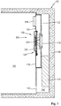
- Fig. 3 shows a half-sectional view of a built-in refrigerator 100 fan unit 130, wherein the fan assembly 108 is received in the housing 116.
- Fig. 3 Shown in Fig. 3 is one of three bearing domes 300 in the present embodiment, which extends through one of the three passage opening 244.
- the three bearing domes 300 are arranged in the present embodiment on a circular path with a uniform angle of 120 ° from each other.
- the bearing dome 300 is integrally formed on the rear housing part 122.
- the bearing dome 300 like the plastic housing back portion 122, e.g. medium injection molding, be made.
- the housing rear portion 122 with the bearing dome 300 is thus integrally formed in the present embodiment.
- the suction nozzle 118 is integrally formed on the rear side 112 of the housing.
- Figure 3 also shows that in the present embodiment, the air outlet opening 114 is associated with the housing front side portion 120.
- a housing front-side catch element 302 is arranged on the housing front side part 120.
- the housing front-side latching element 302 is designed as a latching hook 304.
- the latching hook 304 is integrally formed on the housing front side part 120 in the present embodiment.
- the latching hook 304 like the housing front side part 120, may be made of plastic, eg medium injection molding.
- the Housing front side part 120 with the latching hook 304 is thus integrally formed in the present embodiment.
- Fig. 4 shows that in the fan unit 130 in the present embodiment, the latching hook 304 extends over the entire width B of the housing 116 in the extension direction of the rotation axis I up to a rear side 400 of the housing rear side part 122.
- the rear housing part 122 forms a rear housing latching element 402, which forms a latching connection 404 in contact with the latching hook 304, connecting the housing front side part 120 and the rear housing part 122 to one another.
- the catch hook 304 in the present exemplary embodiment has a joining bevel 412, which simplifies assembly, since it causes an independent deflection of the latching hook 304 during assembly.
- Fig. 4 shows Fig. 4 in that the bearing dome 300 extends through the passage opening 242 of the decoupling element 230. To fix the decoupling element 230, the bearing dome 300 has a collar 408 at its distal end 406.
- the housing front side part 120 has an abutment 410.
- the counter bearing 410 is formed according to the invention on the housing front side portion 120.
- the counter-bearing 410 like the housing front side part 120, may be made of plastic, eg medium injection molding.
- the housing front side part 120 with the abutment 410 is thus formed in one piece.
- the abutment 410 cooperates with the bearing dome 300, which is in contact with the abutment 410 at its distal end 406 for this purpose.
- the abutment 410 may form a further latching connection together with the bearing dome 300 in order to fix the bearing dome 300 at its distal end 406.
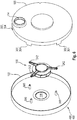
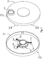
- the Fig. 5 and 6 show the fan assembly 108, which has three through holes 242 in the present embodiment. Furthermore, the show Fig. 5 and 6 the housing rear side part 122 with the rear side 400 formed in the present embodiment as a rear housing locking element 402. Further, the housing front side 122 in the present embodiment, three bearing dome 300, which are integrally formed on the housing front side 122 and the molded suction nozzle 118 on. Finally, the show Fig. 5 and 6 the housing front side portion 120 with three bearing points in the present embodiment 410. Further, the housing front side portion 120 in the present embodiment has six formed as latching hooks 304 housing front side locking elements 302 which are integrally formed on the housing front side portion 120, and the air outlet opening 114.
- Fig. 7 shows a first step of the assembly.
- the fan assembly 108 is displaced such that the bearing domes 300 extend through the through-holes 242. This shift is made by the Confederation 408 (see Fig. 4 ) stopped, so the in Fig. 7 shown position is reached, in which the fan assembly 108 is connected to the rear housing part 122.
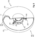
- Fig. 8 shows a further step of assembly.
- the housing front side part 120 is displaced so far until the six latching hooks 304 snap over the rear side 400 of the rear housing part 122 and so the latching connection 404 is formed. Subsequently, the fan unit 130 thus mounted can be installed in the refrigeration device 100.
Landscapes
- Engineering & Computer Science (AREA)
- Mechanical Engineering (AREA)
- General Engineering & Computer Science (AREA)
- Chemical & Material Sciences (AREA)
- Combustion & Propulsion (AREA)
- Physics & Mathematics (AREA)
- Thermal Sciences (AREA)
- Structures Of Non-Positive Displacement Pumps (AREA)
- Cold Air Circulating Systems And Constructional Details In Refrigerators (AREA)
- Devices That Are Associated With Refrigeration Equipment (AREA)
- Air-Conditioning For Vehicles (AREA)
Claims (12)
- Appareil frigorifique (100) comprenant un module de ventilateur (108) qui est logé dans un boîtier (116) comportant une pièce de face avant de boîtier (120) et une pièce de face arrière de boîtier (122), dans lequel le module de ventilateur (108) est fixé à la pièce de face arrière de boîtier (122) et est bloqué par la pièce de face avant de boîtier (120), et la pièce de face arrière de boîtier (122) comprend au moins une calotte de palier (300) pour monter le module de ventilateur (108),
caractérisé en ce que la calotte de palier (300) entre en contact avec un contre-appui (410) pour bloquer le module de ventilateur (108), de manière à empêcher un déplacement du module de ventilateur (108), dans lequel le contre-appui (410) est une partie saillante dans la pièce de face avant de boîtier (120). - Appareil frigorifique (100) selon la revendication 1, caractérisé en ce que la pièce de face arrière de boîtier (121) comprend trois calottes de palier (300) pour monter le module de ventilateur (108).
- Appareil frigorifique (100) selon la revendication 2, caractérisé en ce que les trois calottes de palier (300) sont disposées sur un cercle respectivement à un angle de 120 ° l'un par rapport à l'autre.
- Appareil frigorifique (100) selon l'une des revendications 1 à 3, caractérisé en ce qu'un élément de désaccouplement (230) est agencé entre la calotte de palier (300) et le module de ventilateur (108).
- Appareil frigorifique (100) selon la revendication 4, caractérisé en ce que l'élément de désaccouplement (230) est une pièce moulée en caoutchouc élastique.
- Appareil frigorifique (100) selon l'une des revendications 4 ou 5, caractérisé en ce que l'élément de désaccouplement (230) peut être monté sur la calotte de palier (300).
- Appareil frigorifique (100) selon l'une des revendications 1 à 6, caractérisé en ce que la calotte de palier (300) comprend une partie formant broche comportant une butée pour monter le module de ventilateur (108).
- Appareil frigorifique (100) selon l'une des revendications 1 à 7, caractérisé en ce que la calotte de palier (300) est formée d'une seule pièce avec la pièce de face arrière de boîtier (122).
- Appareil frigorifique (100) selon l'une des revendications 1 à 8, caractérisé en ce que la calotte de palier (300) est cylindrique.
- Appareil frigorifique (100) selon l'une des revendications précédentes, caractérisé en ce que le module de ventilateur (108) comprend un support (126) pour monter le module de ventilateur (108) et pour maintenir une roue de ventilateur (124).
- Appareil frigorifique (100) selon l'une des revendications précédentes, caractérisé en ce que la pièce de face avant de boîtier (302) comprend un élément d'encliquetage (302) de face avant de boîtier à encliqueter dans la pièce de face arrière de boîtier (122) ou la pièce de face arrière de boîtier (122) comprend un élément d'encliquetage de face arrière de boîtier (402) à encliqueter dans l'élément d'encliquetage (302) de face avant de boîtier.
- Appareil frigorifique (100) selon l'une des revendications précédentes, caractérisé en ce que le module de ventilateur (108) est coincé entre la pièce de face avant de boîtier (120) et la pièce de face arrière de boîtier (122).
Applications Claiming Priority (2)
| Application Number | Priority Date | Filing Date | Title |
|---|---|---|---|
| DE201210218347 DE102012218347A1 (de) | 2012-10-09 | 2012-10-09 | Lüftereinheit |
| PCT/EP2013/070392 WO2014056752A1 (fr) | 2012-10-09 | 2013-10-01 | Unité ventilateur |
Publications (2)
| Publication Number | Publication Date |
|---|---|
| EP2906886A1 EP2906886A1 (fr) | 2015-08-19 |
| EP2906886B1 true EP2906886B1 (fr) | 2019-12-11 |
Family
ID=49304924
Family Applications (1)
| Application Number | Title | Priority Date | Filing Date |
|---|---|---|---|
| EP13773676.5A Active EP2906886B1 (fr) | 2012-10-09 | 2013-10-01 | Unité de ventilateur |
Country Status (6)
| Country | Link |
|---|---|
| US (1) | US9970460B2 (fr) |
| EP (1) | EP2906886B1 (fr) |
| CN (1) | CN104823009B (fr) |
| DE (1) | DE102012218347A1 (fr) |
| RU (1) | RU2629974C2 (fr) |
| WO (1) | WO2014056752A1 (fr) |
Families Citing this family (7)
| Publication number | Priority date | Publication date | Assignee | Title |
|---|---|---|---|---|
| DE102016220191A1 (de) * | 2016-10-17 | 2018-04-19 | BSH Hausgeräte GmbH | Kältegerät mit einem Lüfter und einem Entkopplungselement |
| DE102017206505A1 (de) | 2017-04-18 | 2018-10-18 | BSH Hausgeräte GmbH | Kältegerät mit einer Dämpfungsscheibe |
| KR102016227B1 (ko) * | 2017-11-28 | 2019-08-29 | 엘지전자 주식회사 | 팬 조립체 및 이를 포함하는 냉장고 |
| RU2734516C1 (ru) * | 2019-10-01 | 2020-10-19 | Федеральное государственное бюджетное образовательное учреждение высшего образования "Курганский государственный университет" | Вентиляторная установка с диффузорным выходом |
| RU2731486C1 (ru) * | 2019-10-01 | 2020-09-03 | Федеральное государственное бюджетное образовательное учреждение высшего образования "Курганский государственный университет" | Кожух вентиляторной установки с дополнительными воздушными каналами |
| CN116181671A (zh) | 2021-11-26 | 2023-05-30 | 广泰电机(吴江)有限公司 | 一种便于拆卸的单流道双风扇 |
| DE102024207896A1 (de) | 2024-08-20 | 2026-02-26 | BSH Hausgeräte GmbH | Kältegerät, Wärmetauscherbaugruppe für ein Kältegerät und Befestigungsstruktur |
Family Cites Families (12)
| Publication number | Priority date | Publication date | Assignee | Title |
|---|---|---|---|---|
| JP2620718B2 (ja) | 1989-07-12 | 1997-06-18 | 株式会社ゼクセル | ブロワモータの取付構造 |
| JP3307847B2 (ja) * | 1997-01-31 | 2002-07-24 | ホシザキ電機株式会社 | 冷蔵庫等の送風装置 |
| US6000919A (en) * | 1999-02-17 | 1999-12-14 | Hsieh; Hsin-Mao | Fan with reduced thickness |
| US6351380B1 (en) * | 1999-11-12 | 2002-02-26 | Dell Products, L.P. | Cooling fan mounting arrangement |
| US6547516B2 (en) | 2001-08-21 | 2003-04-15 | Hon Hai Precision Ind. Co., Ltd. | Fan bracket |
| BR0201397B1 (pt) | 2002-04-19 | 2011-10-18 | arranjo de montagem para um ventilador de refrigerador. | |
| EP1493317B1 (fr) * | 2003-07-02 | 2006-08-23 | HONDA MOTOR CO., Ltd. | Débroussailleuse |
| US20050095121A1 (en) * | 2003-11-05 | 2005-05-05 | Anand Vithani | Unitary fan-motor grill assembly |
| DE202005014370U1 (de) | 2005-09-12 | 2006-07-20 | BSH Bosch und Siemens Hausgeräte GmbH | No-Frost-Kältegerät |
| JP4192200B1 (ja) | 2007-11-28 | 2008-12-03 | 株式会社東芝 | 冷凍冷蔵庫 |
| KR101427269B1 (ko) * | 2007-12-28 | 2014-08-06 | 엘지전자 주식회사 | 냉장고 |
| CN101639083B (zh) | 2008-07-30 | 2011-12-28 | 富准精密工业(深圳)有限公司 | 离心散热风扇及其扇框 |
-
2012
- 2012-10-09 DE DE201210218347 patent/DE102012218347A1/de not_active Withdrawn
-
2013
- 2013-10-01 WO PCT/EP2013/070392 patent/WO2014056752A1/fr not_active Ceased
- 2013-10-01 EP EP13773676.5A patent/EP2906886B1/fr active Active
- 2013-10-01 RU RU2015114411A patent/RU2629974C2/ru not_active IP Right Cessation
- 2013-10-01 US US14/434,176 patent/US9970460B2/en not_active Expired - Fee Related
- 2013-10-01 CN CN201380052900.4A patent/CN104823009B/zh not_active Expired - Fee Related
Non-Patent Citations (1)
| Title |
|---|
| None * |
Also Published As
| Publication number | Publication date |
|---|---|
| CN104823009A (zh) | 2015-08-05 |
| CN104823009B (zh) | 2017-06-20 |
| US20150292520A1 (en) | 2015-10-15 |
| RU2015114411A (ru) | 2016-12-10 |
| RU2629974C2 (ru) | 2017-09-05 |
| EP2906886A1 (fr) | 2015-08-19 |
| DE102012218347A1 (de) | 2014-05-15 |
| WO2014056752A1 (fr) | 2014-04-17 |
| US9970460B2 (en) | 2018-05-15 |
Similar Documents
| Publication | Publication Date | Title |
|---|---|---|
| WO2014056752A1 (fr) | Unité ventilateur | |
| EP2376787A1 (fr) | Hélice de ventilateur | |
| WO2018192758A1 (fr) | Appareil frigorifique muni d'un disque d'amortissement | |
| EP2281156B1 (fr) | Appareil frigorifique doté d'une surface d'évaporateur rabattue et un procédé de montage d'un appareil frigorifique | |
| EP2536984B1 (fr) | Appareil frigorifique comportant un dispositif de fixation pour un compresseur et procédé de montage d'un compresseur | |
| EP2812639B1 (fr) | Refrigerateur avec un ventilateur et une methode pour le montage du ventilateur | |
| WO2014060311A1 (fr) | Ensemble ventilateur | |
| WO2025195871A1 (fr) | Dispositif de capteur destiné à être fixé à un tuyau et procédé de montage du dispositif de capteur sur un tuyau | |
| DE102016220191A1 (de) | Kältegerät mit einem Lüfter und einem Entkopplungselement | |
| WO2004023049A1 (fr) | Ensemble echangeur de chaleur et turbine | |
| EP2788696B1 (fr) | Appareil frigorifique à bac d'évaporation | |
| EP2743621B1 (fr) | Appareil frigorifique avec tablette | |
| EP2836776B1 (fr) | Appareil frigorifique muni d'une unité de ventilation | |
| DE102019209959A1 (de) | Haushaltsgerätevorrichtung | |
| WO2015018645A1 (fr) | Réfrigérateur équipé d'un clapet d'aération | |
| WO2013182432A1 (fr) | Appareil de froid muni d'une pièce d'amortissement présentant une certaine forme | |
| EP3019800B1 (fr) | Appareil frigorifique pourvu d'un canal d'air | |
| DE102008048019A1 (de) | Taumelscheibengetriebe | |
| DE102024207896A1 (de) | Kältegerät, Wärmetauscherbaugruppe für ein Kältegerät und Befestigungsstruktur | |
| DE102016224985A1 (de) | Haushaltsgerätevorrichtung | |
| DE102014225382A1 (de) | Haushaltsgerätevorrichtung | |
| EP3162173A1 (fr) | Appareil ménager | |
| EP2520884A2 (fr) | Appareil frigorifique | |
| WO2018019580A1 (fr) | Appareil frigorifique muni d'un récipient d'évaporation | |
| WO2012028447A2 (fr) | Appareil de froid |
Legal Events
| Date | Code | Title | Description |
|---|---|---|---|
| PUAI | Public reference made under article 153(3) epc to a published international application that has entered the european phase |
Free format text: ORIGINAL CODE: 0009012 |
|
| 17P | Request for examination filed |
Effective date: 20150511 |
|
| AK | Designated contracting states |
Kind code of ref document: A1 Designated state(s): AL AT BE BG CH CY CZ DE DK EE ES FI FR GB GR HR HU IE IS IT LI LT LU LV MC MK MT NL NO PL PT RO RS SE SI SK SM TR |
|
| AX | Request for extension of the european patent |
Extension state: BA ME |
|
| DAX | Request for extension of the european patent (deleted) | ||
| 17Q | First examination report despatched |
Effective date: 20160726 |
|
| STAA | Information on the status of an ep patent application or granted ep patent |
Free format text: STATUS: EXAMINATION IS IN PROGRESS |
|
| REG | Reference to a national code |
Ref country code: DE Ref legal event code: R079 Ref document number: 502013014059 Country of ref document: DE Free format text: PREVIOUS MAIN CLASS: F25D0017060000 Ipc: F04D0029420000 |
|
| GRAP | Despatch of communication of intention to grant a patent |
Free format text: ORIGINAL CODE: EPIDOSNIGR1 |
|
| STAA | Information on the status of an ep patent application or granted ep patent |
Free format text: STATUS: GRANT OF PATENT IS INTENDED |
|
| RIC1 | Information provided on ipc code assigned before grant |
Ipc: F04D 29/60 20060101ALI20190607BHEP Ipc: F04D 29/62 20060101ALI20190607BHEP Ipc: F25D 17/06 20060101ALI20190607BHEP Ipc: F04D 29/42 20060101AFI20190607BHEP Ipc: F04D 29/66 20060101ALI20190607BHEP |
|
| INTG | Intention to grant announced |
Effective date: 20190705 |
|
| GRAS | Grant fee paid |
Free format text: ORIGINAL CODE: EPIDOSNIGR3 |
|
| GRAA | (expected) grant |
Free format text: ORIGINAL CODE: 0009210 |
|
| STAA | Information on the status of an ep patent application or granted ep patent |
Free format text: STATUS: THE PATENT HAS BEEN GRANTED |
|
| AK | Designated contracting states |
Kind code of ref document: B1 Designated state(s): AL AT BE BG CH CY CZ DE DK EE ES FI FR GB GR HR HU IE IS IT LI LT LU LV MC MK MT NL NO PL PT RO RS SE SI SK SM TR |
|
| REG | Reference to a national code |
Ref country code: GB Ref legal event code: FG4D Free format text: NOT ENGLISH |
|
| REG | Reference to a national code |
Ref country code: CH Ref legal event code: EP |
|
| REG | Reference to a national code |
Ref country code: AT Ref legal event code: REF Ref document number: 1212468 Country of ref document: AT Kind code of ref document: T Effective date: 20191215 |
|
| REG | Reference to a national code |
Ref country code: DE Ref legal event code: R096 Ref document number: 502013014059 Country of ref document: DE |
|
| REG | Reference to a national code |
Ref country code: IE Ref legal event code: FG4D Free format text: LANGUAGE OF EP DOCUMENT: GERMAN |
|
| REG | Reference to a national code |
Ref country code: NL Ref legal event code: MP Effective date: 20191211 |
|
| REG | Reference to a national code |
Ref country code: LT Ref legal event code: MG4D |
|
| PG25 | Lapsed in a contracting state [announced via postgrant information from national office to epo] |
Ref country code: GR Free format text: LAPSE BECAUSE OF FAILURE TO SUBMIT A TRANSLATION OF THE DESCRIPTION OR TO PAY THE FEE WITHIN THE PRESCRIBED TIME-LIMIT Effective date: 20200312 Ref country code: NO Free format text: LAPSE BECAUSE OF FAILURE TO SUBMIT A TRANSLATION OF THE DESCRIPTION OR TO PAY THE FEE WITHIN THE PRESCRIBED TIME-LIMIT Effective date: 20200311 Ref country code: LT Free format text: LAPSE BECAUSE OF FAILURE TO SUBMIT A TRANSLATION OF THE DESCRIPTION OR TO PAY THE FEE WITHIN THE PRESCRIBED TIME-LIMIT Effective date: 20191211 Ref country code: SE Free format text: LAPSE BECAUSE OF FAILURE TO SUBMIT A TRANSLATION OF THE DESCRIPTION OR TO PAY THE FEE WITHIN THE PRESCRIBED TIME-LIMIT Effective date: 20191211 Ref country code: LV Free format text: LAPSE BECAUSE OF FAILURE TO SUBMIT A TRANSLATION OF THE DESCRIPTION OR TO PAY THE FEE WITHIN THE PRESCRIBED TIME-LIMIT Effective date: 20191211 Ref country code: FI Free format text: LAPSE BECAUSE OF FAILURE TO SUBMIT A TRANSLATION OF THE DESCRIPTION OR TO PAY THE FEE WITHIN THE PRESCRIBED TIME-LIMIT Effective date: 20191211 Ref country code: BG Free format text: LAPSE BECAUSE OF FAILURE TO SUBMIT A TRANSLATION OF THE DESCRIPTION OR TO PAY THE FEE WITHIN THE PRESCRIBED TIME-LIMIT Effective date: 20200311 |
|
| PG25 | Lapsed in a contracting state [announced via postgrant information from national office to epo] |
Ref country code: RS Free format text: LAPSE BECAUSE OF FAILURE TO SUBMIT A TRANSLATION OF THE DESCRIPTION OR TO PAY THE FEE WITHIN THE PRESCRIBED TIME-LIMIT Effective date: 20191211 Ref country code: HR Free format text: LAPSE BECAUSE OF FAILURE TO SUBMIT A TRANSLATION OF THE DESCRIPTION OR TO PAY THE FEE WITHIN THE PRESCRIBED TIME-LIMIT Effective date: 20191211 |
|
| PG25 | Lapsed in a contracting state [announced via postgrant information from national office to epo] |
Ref country code: AL Free format text: LAPSE BECAUSE OF FAILURE TO SUBMIT A TRANSLATION OF THE DESCRIPTION OR TO PAY THE FEE WITHIN THE PRESCRIBED TIME-LIMIT Effective date: 20191211 |
|
| PG25 | Lapsed in a contracting state [announced via postgrant information from national office to epo] |
Ref country code: EE Free format text: LAPSE BECAUSE OF FAILURE TO SUBMIT A TRANSLATION OF THE DESCRIPTION OR TO PAY THE FEE WITHIN THE PRESCRIBED TIME-LIMIT Effective date: 20191211 Ref country code: PT Free format text: LAPSE BECAUSE OF FAILURE TO SUBMIT A TRANSLATION OF THE DESCRIPTION OR TO PAY THE FEE WITHIN THE PRESCRIBED TIME-LIMIT Effective date: 20200506 Ref country code: RO Free format text: LAPSE BECAUSE OF FAILURE TO SUBMIT A TRANSLATION OF THE DESCRIPTION OR TO PAY THE FEE WITHIN THE PRESCRIBED TIME-LIMIT Effective date: 20191211 Ref country code: CZ Free format text: LAPSE BECAUSE OF FAILURE TO SUBMIT A TRANSLATION OF THE DESCRIPTION OR TO PAY THE FEE WITHIN THE PRESCRIBED TIME-LIMIT Effective date: 20191211 Ref country code: ES Free format text: LAPSE BECAUSE OF FAILURE TO SUBMIT A TRANSLATION OF THE DESCRIPTION OR TO PAY THE FEE WITHIN THE PRESCRIBED TIME-LIMIT Effective date: 20191211 Ref country code: NL Free format text: LAPSE BECAUSE OF FAILURE TO SUBMIT A TRANSLATION OF THE DESCRIPTION OR TO PAY THE FEE WITHIN THE PRESCRIBED TIME-LIMIT Effective date: 20191211 |
|
| PG25 | Lapsed in a contracting state [announced via postgrant information from national office to epo] |
Ref country code: SM Free format text: LAPSE BECAUSE OF FAILURE TO SUBMIT A TRANSLATION OF THE DESCRIPTION OR TO PAY THE FEE WITHIN THE PRESCRIBED TIME-LIMIT Effective date: 20191211 Ref country code: SK Free format text: LAPSE BECAUSE OF FAILURE TO SUBMIT A TRANSLATION OF THE DESCRIPTION OR TO PAY THE FEE WITHIN THE PRESCRIBED TIME-LIMIT Effective date: 20191211 Ref country code: IS Free format text: LAPSE BECAUSE OF FAILURE TO SUBMIT A TRANSLATION OF THE DESCRIPTION OR TO PAY THE FEE WITHIN THE PRESCRIBED TIME-LIMIT Effective date: 20200411 |
|
| REG | Reference to a national code |
Ref country code: DE Ref legal event code: R097 Ref document number: 502013014059 Country of ref document: DE |
|
| PLBE | No opposition filed within time limit |
Free format text: ORIGINAL CODE: 0009261 |
|
| STAA | Information on the status of an ep patent application or granted ep patent |
Free format text: STATUS: NO OPPOSITION FILED WITHIN TIME LIMIT |
|
| PG25 | Lapsed in a contracting state [announced via postgrant information from national office to epo] |
Ref country code: DK Free format text: LAPSE BECAUSE OF FAILURE TO SUBMIT A TRANSLATION OF THE DESCRIPTION OR TO PAY THE FEE WITHIN THE PRESCRIBED TIME-LIMIT Effective date: 20191211 |
|
| 26N | No opposition filed |
Effective date: 20200914 |
|
| PG25 | Lapsed in a contracting state [announced via postgrant information from national office to epo] |
Ref country code: SI Free format text: LAPSE BECAUSE OF FAILURE TO SUBMIT A TRANSLATION OF THE DESCRIPTION OR TO PAY THE FEE WITHIN THE PRESCRIBED TIME-LIMIT Effective date: 20191211 Ref country code: PL Free format text: LAPSE BECAUSE OF FAILURE TO SUBMIT A TRANSLATION OF THE DESCRIPTION OR TO PAY THE FEE WITHIN THE PRESCRIBED TIME-LIMIT Effective date: 20191211 |
|
| PG25 | Lapsed in a contracting state [announced via postgrant information from national office to epo] |
Ref country code: IT Free format text: LAPSE BECAUSE OF FAILURE TO SUBMIT A TRANSLATION OF THE DESCRIPTION OR TO PAY THE FEE WITHIN THE PRESCRIBED TIME-LIMIT Effective date: 20191211 |
|
| REG | Reference to a national code |
Ref country code: CH Ref legal event code: PL |
|
| GBPC | Gb: european patent ceased through non-payment of renewal fee |
Effective date: 20201001 |
|
| PG25 | Lapsed in a contracting state [announced via postgrant information from national office to epo] |
Ref country code: MC Free format text: LAPSE BECAUSE OF FAILURE TO SUBMIT A TRANSLATION OF THE DESCRIPTION OR TO PAY THE FEE WITHIN THE PRESCRIBED TIME-LIMIT Effective date: 20191211 Ref country code: LU Free format text: LAPSE BECAUSE OF NON-PAYMENT OF DUE FEES Effective date: 20201001 |
|
| REG | Reference to a national code |
Ref country code: BE Ref legal event code: MM Effective date: 20201031 |
|
| PG25 | Lapsed in a contracting state [announced via postgrant information from national office to epo] |
Ref country code: FR Free format text: LAPSE BECAUSE OF NON-PAYMENT OF DUE FEES Effective date: 20201031 |
|
| PG25 | Lapsed in a contracting state [announced via postgrant information from national office to epo] |
Ref country code: GB Free format text: LAPSE BECAUSE OF NON-PAYMENT OF DUE FEES Effective date: 20201001 Ref country code: LI Free format text: LAPSE BECAUSE OF NON-PAYMENT OF DUE FEES Effective date: 20201031 Ref country code: BE Free format text: LAPSE BECAUSE OF NON-PAYMENT OF DUE FEES Effective date: 20201031 Ref country code: CH Free format text: LAPSE BECAUSE OF NON-PAYMENT OF DUE FEES Effective date: 20201031 |
|
| PG25 | Lapsed in a contracting state [announced via postgrant information from national office to epo] |
Ref country code: IE Free format text: LAPSE BECAUSE OF NON-PAYMENT OF DUE FEES Effective date: 20201001 |
|
| REG | Reference to a national code |
Ref country code: AT Ref legal event code: MM01 Ref document number: 1212468 Country of ref document: AT Kind code of ref document: T Effective date: 20201001 |
|
| PG25 | Lapsed in a contracting state [announced via postgrant information from national office to epo] |
Ref country code: AT Free format text: LAPSE BECAUSE OF NON-PAYMENT OF DUE FEES Effective date: 20201001 |
|
| PG25 | Lapsed in a contracting state [announced via postgrant information from national office to epo] |
Ref country code: TR Free format text: LAPSE BECAUSE OF FAILURE TO SUBMIT A TRANSLATION OF THE DESCRIPTION OR TO PAY THE FEE WITHIN THE PRESCRIBED TIME-LIMIT Effective date: 20191211 Ref country code: MT Free format text: LAPSE BECAUSE OF FAILURE TO SUBMIT A TRANSLATION OF THE DESCRIPTION OR TO PAY THE FEE WITHIN THE PRESCRIBED TIME-LIMIT Effective date: 20191211 Ref country code: CY Free format text: LAPSE BECAUSE OF FAILURE TO SUBMIT A TRANSLATION OF THE DESCRIPTION OR TO PAY THE FEE WITHIN THE PRESCRIBED TIME-LIMIT Effective date: 20191211 |
|
| PG25 | Lapsed in a contracting state [announced via postgrant information from national office to epo] |
Ref country code: MK Free format text: LAPSE BECAUSE OF FAILURE TO SUBMIT A TRANSLATION OF THE DESCRIPTION OR TO PAY THE FEE WITHIN THE PRESCRIBED TIME-LIMIT Effective date: 20191211 |
|
| PGFP | Annual fee paid to national office [announced via postgrant information from national office to epo] |
Ref country code: DE Payment date: 20221031 Year of fee payment: 10 |
|
| REG | Reference to a national code |
Ref country code: DE Ref legal event code: R119 Ref document number: 502013014059 Country of ref document: DE |
|
| PG25 | Lapsed in a contracting state [announced via postgrant information from national office to epo] |
Ref country code: DE Free format text: LAPSE BECAUSE OF NON-PAYMENT OF DUE FEES Effective date: 20240501 |