EP2907151B1 - Connecteur ayant des capacités de commande sans fil - Google Patents
Connecteur ayant des capacités de commande sans fil Download PDFInfo
- Publication number
- EP2907151B1 EP2907151B1 EP13844985.5A EP13844985A EP2907151B1 EP 2907151 B1 EP2907151 B1 EP 2907151B1 EP 13844985 A EP13844985 A EP 13844985A EP 2907151 B1 EP2907151 B1 EP 2907151B1
- Authority
- EP
- European Patent Office
- Prior art keywords
- connector
- recited
- load
- interface
- power
- Prior art date
- Legal status (The legal status is an assumption and is not a legal conclusion. Google has not performed a legal analysis and makes no representation as to the accuracy of the status listed.)
- Active
Links
Images

Classifications
-
- H—ELECTRICITY
- H02—GENERATION; CONVERSION OR DISTRIBUTION OF ELECTRIC POWER
- H02J—ELECTRIC POWER NETWORKS; CIRCUIT ARRANGEMENTS OR SYSTEMS FOR SUPPLYING OR DISTRIBUTING ELECTRIC POWER; SYSTEMS FOR STORING ELECTRIC ENERGY
- H02J13/00—Circuit arrangements for providing remote monitoring or remote control of equipment in a power distribution network
- H02J13/13—Circuit arrangements for providing remote monitoring or remote control of equipment in a power distribution network characterised by the transmission of data to equipment in the power network
- H02J13/1331—Circuit arrangements for providing remote monitoring or remote control of equipment in a power distribution network characterised by the transmission of data to equipment in the power network using wireless data transmission
-
- H—ELECTRICITY
- H01—ELECTRIC ELEMENTS
- H01H—ELECTRIC SWITCHES; RELAYS; SELECTORS; EMERGENCY PROTECTIVE DEVICES
- H01H9/00—Details of switching devices, not covered by groups H01H1/00 - H01H7/00
- H01H9/54—Circuit arrangements not adapted to a particular application of the switching device and for which no provision exists elsewhere
-
- H—ELECTRICITY
- H02—GENERATION; CONVERSION OR DISTRIBUTION OF ELECTRIC POWER
- H02J—ELECTRIC POWER NETWORKS; CIRCUIT ARRANGEMENTS OR SYSTEMS FOR SUPPLYING OR DISTRIBUTING ELECTRIC POWER; SYSTEMS FOR STORING ELECTRIC ENERGY
- H02J3/00—Circuit arrangements for AC mains or AC distribution networks
-
- H—ELECTRICITY
- H05—ELECTRIC TECHNIQUES NOT OTHERWISE PROVIDED FOR
- H05B—ELECTRIC HEATING; ELECTRIC LIGHT SOURCES NOT OTHERWISE PROVIDED FOR; CIRCUIT ARRANGEMENTS FOR ELECTRIC LIGHT SOURCES, IN GENERAL
- H05B47/00—Circuit arrangements for operating light sources in general, i.e. where the type of light source is not relevant
- H05B47/10—Controlling the light source
- H05B47/105—Controlling the light source in response to determined parameters
-
- H—ELECTRICITY
- H05—ELECTRIC TECHNIQUES NOT OTHERWISE PROVIDED FOR
- H05B—ELECTRIC HEATING; ELECTRIC LIGHT SOURCES NOT OTHERWISE PROVIDED FOR; CIRCUIT ARRANGEMENTS FOR ELECTRIC LIGHT SOURCES, IN GENERAL
- H05B47/00—Circuit arrangements for operating light sources in general, i.e. where the type of light source is not relevant
- H05B47/10—Controlling the light source
- H05B47/175—Controlling the light source by remote control
- H05B47/19—Controlling the light source by remote control via wireless transmission
-
- H—ELECTRICITY
- H05—ELECTRIC TECHNIQUES NOT OTHERWISE PROVIDED FOR
- H05B—ELECTRIC HEATING; ELECTRIC LIGHT SOURCES NOT OTHERWISE PROVIDED FOR; CIRCUIT ARRANGEMENTS FOR ELECTRIC LIGHT SOURCES, IN GENERAL
- H05B47/00—Circuit arrangements for operating light sources in general, i.e. where the type of light source is not relevant
- H05B47/10—Controlling the light source
- H05B47/105—Controlling the light source in response to determined parameters
- H05B47/115—Controlling the light source in response to determined parameters by determining the presence or movement of objects or living beings
-
- Y—GENERAL TAGGING OF NEW TECHNOLOGICAL DEVELOPMENTS; GENERAL TAGGING OF CROSS-SECTIONAL TECHNOLOGIES SPANNING OVER SEVERAL SECTIONS OF THE IPC; TECHNICAL SUBJECTS COVERED BY FORMER USPC CROSS-REFERENCE ART COLLECTIONS [XRACs] AND DIGESTS
- Y02—TECHNOLOGIES OR APPLICATIONS FOR MITIGATION OR ADAPTATION AGAINST CLIMATE CHANGE
- Y02E—REDUCTION OF GREENHOUSE GAS [GHG] EMISSIONS, RELATED TO ENERGY GENERATION, TRANSMISSION OR DISTRIBUTION
- Y02E60/00—Enabling technologies; Technologies with a potential or indirect contribution to GHG emissions mitigation
-
- Y—GENERAL TAGGING OF NEW TECHNOLOGICAL DEVELOPMENTS; GENERAL TAGGING OF CROSS-SECTIONAL TECHNOLOGIES SPANNING OVER SEVERAL SECTIONS OF THE IPC; TECHNICAL SUBJECTS COVERED BY FORMER USPC CROSS-REFERENCE ART COLLECTIONS [XRACs] AND DIGESTS
- Y04—INFORMATION OR COMMUNICATION TECHNOLOGIES HAVING AN IMPACT ON OTHER TECHNOLOGY AREAS
- Y04S—SYSTEMS INTEGRATING TECHNOLOGIES RELATED TO POWER NETWORK OPERATION, COMMUNICATION OR INFORMATION TECHNOLOGIES FOR IMPROVING THE ELECTRICAL POWER GENERATION, TRANSMISSION, DISTRIBUTION, MANAGEMENT OR USAGE, i.e. SMART GRIDS
- Y04S40/00—Systems for electrical power generation, transmission, distribution or end-user application management characterised by the use of communication or information technologies, or communication or information technology specific aspects supporting them
- Y04S40/12—Systems for electrical power generation, transmission, distribution or end-user application management characterised by the use of communication or information technologies, or communication or information technology specific aspects supporting them characterised by data transport means between the monitoring, controlling or managing units and monitored, controlled or operated electrical equipment
- Y04S40/126—Systems for electrical power generation, transmission, distribution or end-user application management characterised by the use of communication or information technologies, or communication or information technology specific aspects supporting them characterised by data transport means between the monitoring, controlling or managing units and monitored, controlled or operated electrical equipment using wireless data transmission
Definitions
- the present description relates generally to a wireless smart connector and more particularly to a connector having wireless control capabilities.
- the subject disclosure is generally related to electrical connectors and, more particularly, to an electrical connector having wireless control capabilities for use in connection with an alternating current (AC) power system.
- AC alternating current
- systems and methods of providing an adaptor for bringing wireless communication to a wired sensor include the use of a sensor interface, such as described in US Patent No. 8,275,471 , US Patent No. 7,839,017 , US Patent No. 7,925,384 , US Patent Publication No. 2011/0043052 , and US Patent Publication No. 2011/0043052 .
- the referenced publications describe a system and method for enabling wireless communication with a wired sensor.
- power is continuously supplied to an electrical load device under control of a separate wireless controller.
- the wireless controller includes information stored and/or detected to directly control the electric load device.
- a light fixture includes a lamp controller which controls the operation of a lamp by selectively coupling the power source to the lamp.
- the lamp controller selectively operates the lamp in response to signals received from a remote controller and a light switch, as well as from a motion sensor and a photo sensor.
- the connector is well suited for both retrofit/rehabilitation installations as well as for new construction.
- the subject connectors may be used to couple an AC powered device to any suitable AC powered wireless control system, to any suitable AC power cables, and/or to other disconnection/connection points in an AC power system.
- the subject connectors may be provided with one or more mechanical terminal structures, such as for example, push-in type terminal connectors, to thereby allow the subject connectors to be easily and releasably attached thereto.
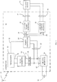
- FIG. 1 a schematic diagram of an exemplary connector 10 for use in bringing power from a power source 12, such as an alternating current (AC) power source to a powered fixture or device 13, such as a light fixture, sensor, or the like, is illustrated.
- a power source 12 such as an alternating current (AC) power source
- a powered fixture or device 13 such as a light fixture, sensor, or the like
- the connector 10 For allowing the connector 10 to be coupled to the power source 12, the connector 10 includes a line-side interface 14 comprised of one or more electrical contacts arranged to allow engagement with corresponding electrical conductors or surfaces associated with the power source 12.
- the electrical contacts of the line-side interface 14 may be incorporated into a housing, such as for example a non-conductive housing, having mechanical structures as needed to allow the connector 10 to be releasably attached to a power grid system, power cables, and/or to other disconnection/connection points in a power system.
- the wireless connector 10 may also be attached to conductors, such as wires, associated with the source of AC power through use of insulation piercing type contacts (IPC type contacts), insulation displacing type contacts (IDC type contacts), push-in type contacts, crimp type contacts, weld type contacts, etc.
- IPC type contacts insulation piercing type contacts
- IDC type contacts insulation displacing type contacts
- push-in type contacts crimp type contacts
- weld type contacts etc.
- the connector 10 For allowing the connector 10 to be coupled to the powered device 13, the connector 10 includes a load-side power interface 16 and a load-side control interface 18 comprising one or more electrical contacts (which one or more electrical contacts may be incorporated into the same or a further housing having mechanical structures as needed) adapted to be engaged with wires 17, 19, respectively, plugs, or the like, that are associated with the powered device 13.
- the example load-side power interface provides AC power to the device 13, while the example load-side control interface 18 provide a control signal, such as for example, a dim, flash, brighten, chase, turn on, turn off, etc. control signal.
- load-side power interface 16 and the load-side control interface 18 are illustrated in the present example as separate components, it will be appreciated by one of ordinary skill in the art that the interfaces 16, 18 may be integrally and/or separately formed as desired. Additionally, each of the electrical contacts and/or wires 17, 19, may be otherwise combined and/or separated. Still further, without limitation, the electrical contacts of the load-side interface 16 and/or the load-side control interface 18 may be push-in type contacts, IDC type contacts, IPC type contacts, crimp type contacts, weld type contacts, etc.
- the connector 10 further includes a controller 20.
- the example controller 20 is electrically coupled to the line-side interface 14 via an electrical connection 22 and is electrically coupled to the load-side interface 16 via an electrical connection 24.
- the controller 20 is coupled to the load-side control interface 18 via an electrical connection 26.
- the controller 20 may comprise a semiconductor based electronic device such as an Opto-isolator, silicon-controlled rectifier (SCR), field-effect transistor (FET), transistor, microelectromechanical systems (MEMS) switch, and/or any other suitable controller.
- a semiconductor based electronic device such as an Opto-isolator, silicon-controlled rectifier (SCR), field-effect transistor (FET), transistor, microelectromechanical systems (MEMS) switch, and/or any other suitable controller.
- SCR silicon-controlled rectifier
- FET field-effect transistor
- MEMS microelectromechanical systems
- the controller 20 is further coupled to a receiver (e.g., a wireless receiver) or transceiver 30, which, as described hereinafter, functions to provide a control signal to the controller 20 via an electrical connection 32.
- a receiver e.g., a wireless receiver
- transceiver 30 which, as described hereinafter, functions to provide a control signal to the controller 20 via an electrical connection 32.
- Power is provided to the wireless receiver or transceiver 30 by means of an optional DC-DC converter 34, which is electrically coupled to the wireless receiver or transceiver 30 via an electrical connection 36 and to the line-side interface 14 via a rectifier 38 having an electrical connection 40 to the DC-DC converter 34 and an electrical connection 42 to the line-side interface 14.
- the wireless receiver or transceiver 30 may also be directly coupled to the line-side interface 14 and/or the rectifier 38 as desired.
- the wireless receiver or transceiver 30 is adapted to receive and transmit a control signal (e.g., a DC control signal) to the controller 20 via the electrical connection 32 in response to the wireless receiver or transceiver 30 receiving a control signal from a remotely located device 31, e.g., a switch, control center, or the like.
- a remotely located device e.g., a switch, control center, or the like.
- the remotely located device and the wireless receiver or transceiver 30 are adapted to communicate via use of wireless RF transmissions.
- the controller 20 is, in turn, adapted to respond to the control signal transmitted thereto via the electrical connection 32 to control the bringing of power to the load-side interface 16 from the line-side interface 14 via the electrical connections 22 and 24. Additionally, the controller 20 is adapted to respond to the control signal transmitted thereto via the electrical connection 32 to control the bringing of a control signal to the load-side control interface 18 via the electrical connection 26.
- control signal provided to the controller 20 by the wireless receiver or transceiver 30 is used to turn on or turn off the power connection between the load-side power interface 16 and the line-side interface 14.
- control signal provided to the controller 20 by the wireless receiver or transceiver 30 may also be used to provide a controlling signal to the load-side control interface 18 to limit and/or otherwise modify or control the amount of power that is provided to the device 13 e.g., to provide for a dimming effect.
- the load-side control interface may reduce (e.g., dim) the output AC voltage by chopping the AC output for typical incandescent light.
- the load-side control interface may provide an analog (e.g., 0 to 10) volt variable output to dim fluorescent lights.
- the connector 10 may allow for state data associated with the controller 20, and accordingly the device 13, and/or other data to be communicated to other remotely located devices as needed. While not illustrated, the connector 10 may additionally include a mechanism or other means for allowing a user to set (or for pre-setting at a time of manufacture) an address to thereby allow communications to the connector 10, via the receiver or transceiver 30, to be specifically targeted thereto - which would be particularly useful in an instance where multiple connectors are intended to be used in a confined area.
- the connector 10 may be directly coupled to a sensor 200 via a communication link, such as for example, a wire 202 ( FIG. 2 ).
- a communication link such as for example, a wire 202 ( FIG. 2 ).
- the communication link may be wireless, wired, and/or other suitable link as desired.
- the sensor 200 may be capable of communicating directly with the transceiver 30 or may communicate directly with the controller 20.
- the sensor 200 may be adapted to communicate directly with the remotely located device 31, which in turn communicates with the connector 10 as described hereinabove.
- the senor 200 may be adapted to sense an environmental condition, such as a temperature, motion, light level, time of day, etc., and communicate the sensed condition to the connector 10 (either directly or indirectly as shown) for influencing the ultimate performance of the device 13.
- the sensor 200 may detect an ambient light of the room in which the sensor 200 is installed and relay that the relevant information to the connector 10 for influencing the load -side power interface 16 and/or the load-side control interface 18, which in turn influences the performance state of the device 13.
- the connector 10 may be "smart" in that the connector 10 is able to influence the performance of the fixture device to which it is connected in response to an external stimuli.
Landscapes
- Engineering & Computer Science (AREA)
- Power Engineering (AREA)
- Computer Networks & Wireless Communication (AREA)
- Details Of Connecting Devices For Male And Female Coupling (AREA)
- Circuit Arrangement For Electric Light Sources In General (AREA)
- Remote Monitoring And Control Of Power-Distribution Networks (AREA)
Claims (19)
- Connecteur (10) pour connecter une source d'alimentation en courant alternatif (AC) à un dispositif alimenté (13) qui est localisé de sorte qu'il est externe par rapport au connecteur, comprenant :une interface de côté de ligne (14) qui comporte un ou plusieurs contact(s) électrique(s) qui est/sont agencé(s) pour coupler électriquement le connecteur à un ou plusieurs conducteur(s) électrique(s) correspondant(s) qui est/sont associé(s) à la source d'alimentation en courant alternatif ;une interface d'alimentation de côté de charge (16) qui comporte un ou plusieurs contact(s) électrique(s) qui est/sont agencé(s) pour coupler électriquement le connecteur à un ou plusieurs conducteur(s) électrique(s) correspondant(s) qui est/sont associé(s) au dispositif alimenté ;une interface de commande de côté de charge (18) qui comporte un ou plusieurs contact(s) électrique(s) qui est/sont agencé(s) pour coupler électriquement le connecteur à un ou plusieurs conducteur(s) électrique(s) correspondant(s) qui est/sont associé(s) au dispositif alimenté ;un contrôleur (20) qui est couplé électriquement à l'interface de côté de ligne, à l'interface d'alimentation de côté de charge et à l'interface de commande de côté de charge et qui peut être rendu opérationnel de manière à ce qu'il commande un apport de l'alimentation en courant alternatif à l'interface d'alimentation de côté de charge depuis l'interface de côté de ligne pour réaliser une alimentation sur les un ou plusieurs conducteurs électriques correspondants qui sont associés au dispositif alimenté via les un ou plusieurs contacts électriques de l'interface d'alimentation de côté de charge, et qui peut être rendu opérationnel de manière à ce qu'il commande un apport d'un signal de commande (26) sur l'interface de commande de côté de charge pour réaliser une alimentation sur les un ou plusieurs conducteurs électriques correspondants qui sont associés au dispositif alimenté via les un ou plusieurs contacts électriques de l'interface de commande de côté de charge ; etun récepteur (30) qui est couplé électriquement au contrôleur pour recevoir un premier signal en provenance d'une commande (31) qui est externe par rapport au connecteur et pour générer, en réponse à ce signal, un second signal (32) pour commander les opérations du contrôleur.
- Connecteur selon la revendication 1, dans lequel les un ou plusieurs contacts électriques de l'interface de côté de ligne sont agencés pour coupler électriquement de manière libérable le connecteur aux un ou plusieurs conducteurs électriques correspondants qui sont associés à la source d'alimentation en courant alternatif.
- Connecteur selon la revendication 1, dans lequel les un ou plusieurs contacts électriques d'au moins une interface prise parmi l'interface d'alimentation de côté de charge et l'interface de commande de côté de charge comprend au moins un contact pris parmi un contact du type par pression, un contact du type IDC, un contact du type IPC, un contact du type par sertissage et un contact du type par soudage pour engager un ou plusieurs fil(s) correspondant(s) qui est/sont associé(s) au dispositif alimenté.
- Connecteur selon la revendication 1, dans lequel le contrôleur applique un signal électrique sur l'interface de commande de côté de charge de manière à ce qu'elle fonctionne en tant que moyen d'activation/de désactivation pour un contrôleur d'alimentation.
- Connecteur selon la revendication 1, dans lequel le contrôleur applique un signal électrique sur l'interface de commande de côté de charge de manière à commander un contrôleur d'alimentation à variateur.
- Connecteur selon la revendication 1, dans lequel le contrôleur comprend au moins un composant pris parmi un opto-isolateur, un redresseur commandé au silicium (SCR), un transistor à effet de champ (FET), un transistor et un commutateur à systèmes micro-électromécaniques (MEMS).
- Connecteur selon la revendication 1, comprenant en outre un redresseur qui est couplé électriquement au récepteur et à l'interface de côté de ligne pour alimenter en électricité le récepteur.
- Connecteur selon la revendication 7, comprenant en outre un convertisseur DC-DC qui est couplé électriquement entre le redresseur et le récepteur.
- Connecteur selon la revendication 1, dans lequel le récepteur est couplé électriquement directement à l'interface de côté de ligne qui alimente en électricité le récepteur.
- Connecteur selon la revendication 1, comprenant en outre une batterie pour alimenter en électricité le récepteur.
- Connecteur selon la revendication 1, dans lequel le récepteur est un récepteur RF.
- Connecteur selon la revendication 1, dans lequel le récepteur comprend un émetteur - récepteur.
- Connecteur selon la revendication 12, dans lequel l'émetteur - récepteur est un émetteur - récepteur RF.
- Connecteur selon la revendication 1, dans lequel le récepteur est muni d'une adresse.
- Connecteur selon la revendication 14, comprenant un dispositif de définition d'adresse qui est associé au récepteur.
- Connecteur selon la revendication 1, dans lequel au moins deux composants pris parmi l'interface d'alimentation de côté de charge, l'interface de commande de côté de charge et le contrôleur sont formés d'un seul tenant.
- Connecteur selon la revendication 1, comprenant en outre un capteur (200) qui est externe par rapport au connecteur et qui est couplé en termes de communication au connecteur pour fournir des données qui sont indicatives d'un état du capteur au contrôleur.
- Connecteur selon la revendication 17, dans lequel le capteur communique directement avec le connecteur.
- Connecteur selon la revendication 17, dans lequel le capteur communique avec un dispositif intermédiaire (31), lequel à son tour relaie les données qui sont indicatives d'un état qui est associé au capteur au connecteur.
Applications Claiming Priority (2)
| Application Number | Priority Date | Filing Date | Title |
|---|---|---|---|
| US13/650,757 US9660447B2 (en) | 2012-03-02 | 2012-10-12 | Connector having wireless control capabilities |
| PCT/US2013/064303 WO2014059122A2 (fr) | 2012-10-12 | 2013-10-10 | Connecteur ayant des capacités de commande sans fil |
Publications (3)
| Publication Number | Publication Date |
|---|---|
| EP2907151A2 EP2907151A2 (fr) | 2015-08-19 |
| EP2907151A4 EP2907151A4 (fr) | 2016-07-13 |
| EP2907151B1 true EP2907151B1 (fr) | 2019-12-04 |
Family
ID=50474742
Family Applications (1)
| Application Number | Title | Priority Date | Filing Date |
|---|---|---|---|
| EP13844985.5A Active EP2907151B1 (fr) | 2012-10-12 | 2013-10-10 | Connecteur ayant des capacités de commande sans fil |
Country Status (4)
| Country | Link |
|---|---|
| EP (1) | EP2907151B1 (fr) |
| CN (1) | CN104704590B (fr) |
| CA (1) | CA2887153C (fr) |
| WO (1) | WO2014059122A2 (fr) |
Families Citing this family (4)
| Publication number | Priority date | Publication date | Assignee | Title |
|---|---|---|---|---|
| US11353198B2 (en) | 2012-03-02 | 2022-06-07 | Ideal Industries, Inc. | Electrical connector having a printed circuit board for use with an active grid bus bar system |
| CN107425313A (zh) * | 2016-04-21 | 2017-12-01 | 理想工业公司 | 用于有源电网母线系统的具有印刷电路板的电连接器 |
| US11394426B2 (en) | 2016-06-22 | 2022-07-19 | Korrus, Inc. | Intelligent modules for intelligent networks |
| JP2019525536A (ja) | 2016-06-22 | 2019-09-05 | ソラア インコーポレーテッドSoraa Inc. | 知能ネットワークに用いる知能モジュール |
Family Cites Families (13)
| Publication number | Priority date | Publication date | Assignee | Title |
|---|---|---|---|---|
| US5315533A (en) * | 1991-05-17 | 1994-05-24 | Best Power Technology, Inc. | Back-up uninterruptible power system |
| US5598039A (en) * | 1993-03-15 | 1997-01-28 | Touchstone Patent Trust | Method and apparatus for sensing state of electric power flow through a master circuit and producing remote control of a slave circuit |
| US20040084972A1 (en) * | 2002-10-30 | 2004-05-06 | Linsong Weng | Wireless remote time socket apparatus |
| CA2550527A1 (fr) * | 2005-06-21 | 2006-12-21 | Ideal Industries, Inc. | Sectionneur electrique muni de connecteurs a enfoncer |
| US20070247086A1 (en) * | 2006-04-21 | 2007-10-25 | Shih-Yung Chiu | Portable wireless remote-controlled dimmer socket |
| US7638743B2 (en) * | 2007-06-29 | 2009-12-29 | Orion Energy Systems, Inc. | Method and system for controlling a lighting system |
| KR100935186B1 (ko) * | 2007-06-27 | 2010-01-06 | 임성규 | 플러그장치 |
| US8664881B2 (en) * | 2009-11-25 | 2014-03-04 | Lutron Electronics Co., Inc. | Two-wire dimmer switch for low-power loads |
| US8471492B2 (en) * | 2010-11-04 | 2013-06-25 | Daintree Networks, Pty. Ltd. | Wireless adaptation of lighting power supply |
| US20120133217A1 (en) * | 2010-11-26 | 2012-05-31 | Louis Lemire | Control System for an Electrical Apparatus and Method of Using the Same |
| US8514540B2 (en) * | 2011-01-26 | 2013-08-20 | General Electric Company | Smart plug with internal condition-based demand response capability |
| US20130229067A1 (en) * | 2012-03-02 | 2013-09-05 | Ideal Industries, Inc. | Connector having wireless control capabilities |
| EP2793323A1 (fr) * | 2013-04-15 | 2014-10-22 | Ideal Industries Inc. | Prise de courant électrique ayant des capacités de commande sans fil |
-
2013
- 2013-10-10 EP EP13844985.5A patent/EP2907151B1/fr active Active
- 2013-10-10 CA CA2887153A patent/CA2887153C/fr not_active Expired - Fee Related
- 2013-10-10 WO PCT/US2013/064303 patent/WO2014059122A2/fr not_active Ceased
- 2013-10-10 CN CN201380053441.1A patent/CN104704590B/zh not_active Expired - Fee Related
Non-Patent Citations (1)
| Title |
|---|
| None * |
Also Published As
| Publication number | Publication date |
|---|---|
| CA2887153C (fr) | 2020-12-29 |
| CN104704590B (zh) | 2018-04-13 |
| CA2887153A1 (fr) | 2014-04-17 |
| EP2907151A2 (fr) | 2015-08-19 |
| WO2014059122A2 (fr) | 2014-04-17 |
| EP2907151A4 (fr) | 2016-07-13 |
| WO2014059122A3 (fr) | 2014-06-19 |
| CN104704590A (zh) | 2015-06-10 |
Similar Documents
| Publication | Publication Date | Title |
|---|---|---|
| US9660447B2 (en) | Connector having wireless control capabilities | |
| US9602022B2 (en) | Electrical device for use with a multiway switch system | |
| US20130240235A1 (en) | Load-control switch and load-control switch system | |
| US10636290B2 (en) | Communication interface device for a solid-state luminaire | |
| CN107251317B (zh) | 电气设备、包括此类电气设备的系统、以及在此类系统中实现的方法 | |
| EP3354115B1 (fr) | Dispositif de câblage | |
| EP2907151B1 (fr) | Connecteur ayant des capacités de commande sans fil | |
| US9627928B2 (en) | Electrical outlet having wireless control capabilities | |
| US20130106199A1 (en) | Master slave radio control system | |
| EP2637483A2 (fr) | Système de commande destiné à être utilisé avec un ou plusieurs circuits d'alimentation électrique de bâtiment | |
| EP2973885B1 (fr) | Noeud de connecteur sans fil et système | |
| CA2959857C (fr) | Systeme et procede de controle | |
| EP2793323A1 (fr) | Prise de courant électrique ayant des capacités de commande sans fil | |
| CN202870541U (zh) | 一种智能墙壁开关 | |
| JP6997608B2 (ja) | スイッチ回路コントロール装置 | |
| EP3876674B1 (fr) | Ensemble diodes électroluminescentes | |
| CN107659125A (zh) | 应用于多路负载的供电电源、集成式供电电源及照明灯具 | |
| CN107978139B (zh) | 无线遥控开关装置及无线遥控电器 | |
| CN119732178A (zh) | 具有气隙开关受控输出的照明控制设备 | |
| CN111315089A (zh) | 一种隧道人体感应智能灯装置 |
Legal Events
| Date | Code | Title | Description |
|---|---|---|---|
| PUAI | Public reference made under article 153(3) epc to a published international application that has entered the european phase |
Free format text: ORIGINAL CODE: 0009012 |
|
| 17P | Request for examination filed |
Effective date: 20150402 |
|
| AK | Designated contracting states |
Kind code of ref document: A2 Designated state(s): AL AT BE BG CH CY CZ DE DK EE ES FI FR GB GR HR HU IE IS IT LI LT LU LV MC MK MT NL NO PL PT RO RS SE SI SK SM TR |
|
| AX | Request for extension of the european patent |
Extension state: BA ME |
|
| DAX | Request for extension of the european patent (deleted) | ||
| A4 | Supplementary search report drawn up and despatched |
Effective date: 20160610 |
|
| RIC1 | Information provided on ipc code assigned before grant |
Ipc: H05B 37/02 20060101ALI20160606BHEP Ipc: H01R 13/703 20060101ALI20160606BHEP Ipc: H01H 9/54 20060101AFI20160606BHEP Ipc: H02J 13/00 20060101ALI20160606BHEP Ipc: H01R 24/76 20110101ALI20160606BHEP |
|
| GRAP | Despatch of communication of intention to grant a patent |
Free format text: ORIGINAL CODE: EPIDOSNIGR1 |
|
| STAA | Information on the status of an ep patent application or granted ep patent |
Free format text: STATUS: GRANT OF PATENT IS INTENDED |
|
| INTG | Intention to grant announced |
Effective date: 20190612 |
|
| GRAS | Grant fee paid |
Free format text: ORIGINAL CODE: EPIDOSNIGR3 |
|
| GRAA | (expected) grant |
Free format text: ORIGINAL CODE: 0009210 |
|
| STAA | Information on the status of an ep patent application or granted ep patent |
Free format text: STATUS: THE PATENT HAS BEEN GRANTED |
|
| AK | Designated contracting states |
Kind code of ref document: B1 Designated state(s): AL AT BE BG CH CY CZ DE DK EE ES FI FR GB GR HR HU IE IS IT LI LT LU LV MC MK MT NL NO PL PT RO RS SE SI SK SM TR |
|
| REG | Reference to a national code |
Ref country code: GB Ref legal event code: FG4D |
|
| REG | Reference to a national code |
Ref country code: CH Ref legal event code: EP |
|
| REG | Reference to a national code |
Ref country code: AT Ref legal event code: REF Ref document number: 1210435 Country of ref document: AT Kind code of ref document: T Effective date: 20191215 |
|
| REG | Reference to a national code |
Ref country code: DE Ref legal event code: R096 Ref document number: 602013063704 Country of ref document: DE |
|
| REG | Reference to a national code |
Ref country code: IE Ref legal event code: FG4D |
|
| REG | Reference to a national code |
Ref country code: NL Ref legal event code: MP Effective date: 20191204 |
|
| REG | Reference to a national code |
Ref country code: LT Ref legal event code: MG4D |
|
| PG25 | Lapsed in a contracting state [announced via postgrant information from national office to epo] |
Ref country code: GR Free format text: LAPSE BECAUSE OF FAILURE TO SUBMIT A TRANSLATION OF THE DESCRIPTION OR TO PAY THE FEE WITHIN THE PRESCRIBED TIME-LIMIT Effective date: 20200305 Ref country code: BG Free format text: LAPSE BECAUSE OF FAILURE TO SUBMIT A TRANSLATION OF THE DESCRIPTION OR TO PAY THE FEE WITHIN THE PRESCRIBED TIME-LIMIT Effective date: 20200304 Ref country code: FI Free format text: LAPSE BECAUSE OF FAILURE TO SUBMIT A TRANSLATION OF THE DESCRIPTION OR TO PAY THE FEE WITHIN THE PRESCRIBED TIME-LIMIT Effective date: 20191204 Ref country code: SE Free format text: LAPSE BECAUSE OF FAILURE TO SUBMIT A TRANSLATION OF THE DESCRIPTION OR TO PAY THE FEE WITHIN THE PRESCRIBED TIME-LIMIT Effective date: 20191204 Ref country code: LV Free format text: LAPSE BECAUSE OF FAILURE TO SUBMIT A TRANSLATION OF THE DESCRIPTION OR TO PAY THE FEE WITHIN THE PRESCRIBED TIME-LIMIT Effective date: 20191204 Ref country code: NO Free format text: LAPSE BECAUSE OF FAILURE TO SUBMIT A TRANSLATION OF THE DESCRIPTION OR TO PAY THE FEE WITHIN THE PRESCRIBED TIME-LIMIT Effective date: 20200304 Ref country code: LT Free format text: LAPSE BECAUSE OF FAILURE TO SUBMIT A TRANSLATION OF THE DESCRIPTION OR TO PAY THE FEE WITHIN THE PRESCRIBED TIME-LIMIT Effective date: 20191204 |
|
| PG25 | Lapsed in a contracting state [announced via postgrant information from national office to epo] |
Ref country code: RS Free format text: LAPSE BECAUSE OF FAILURE TO SUBMIT A TRANSLATION OF THE DESCRIPTION OR TO PAY THE FEE WITHIN THE PRESCRIBED TIME-LIMIT Effective date: 20191204 Ref country code: HR Free format text: LAPSE BECAUSE OF FAILURE TO SUBMIT A TRANSLATION OF THE DESCRIPTION OR TO PAY THE FEE WITHIN THE PRESCRIBED TIME-LIMIT Effective date: 20191204 |
|
| PG25 | Lapsed in a contracting state [announced via postgrant information from national office to epo] |
Ref country code: AL Free format text: LAPSE BECAUSE OF FAILURE TO SUBMIT A TRANSLATION OF THE DESCRIPTION OR TO PAY THE FEE WITHIN THE PRESCRIBED TIME-LIMIT Effective date: 20191204 |
|
| PG25 | Lapsed in a contracting state [announced via postgrant information from national office to epo] |
Ref country code: EE Free format text: LAPSE BECAUSE OF FAILURE TO SUBMIT A TRANSLATION OF THE DESCRIPTION OR TO PAY THE FEE WITHIN THE PRESCRIBED TIME-LIMIT Effective date: 20191204 Ref country code: CZ Free format text: LAPSE BECAUSE OF FAILURE TO SUBMIT A TRANSLATION OF THE DESCRIPTION OR TO PAY THE FEE WITHIN THE PRESCRIBED TIME-LIMIT Effective date: 20191204 Ref country code: ES Free format text: LAPSE BECAUSE OF FAILURE TO SUBMIT A TRANSLATION OF THE DESCRIPTION OR TO PAY THE FEE WITHIN THE PRESCRIBED TIME-LIMIT Effective date: 20191204 Ref country code: NL Free format text: LAPSE BECAUSE OF FAILURE TO SUBMIT A TRANSLATION OF THE DESCRIPTION OR TO PAY THE FEE WITHIN THE PRESCRIBED TIME-LIMIT Effective date: 20191204 Ref country code: RO Free format text: LAPSE BECAUSE OF FAILURE TO SUBMIT A TRANSLATION OF THE DESCRIPTION OR TO PAY THE FEE WITHIN THE PRESCRIBED TIME-LIMIT Effective date: 20191204 Ref country code: PT Free format text: LAPSE BECAUSE OF FAILURE TO SUBMIT A TRANSLATION OF THE DESCRIPTION OR TO PAY THE FEE WITHIN THE PRESCRIBED TIME-LIMIT Effective date: 20200429 |
|
| PG25 | Lapsed in a contracting state [announced via postgrant information from national office to epo] |
Ref country code: SK Free format text: LAPSE BECAUSE OF FAILURE TO SUBMIT A TRANSLATION OF THE DESCRIPTION OR TO PAY THE FEE WITHIN THE PRESCRIBED TIME-LIMIT Effective date: 20191204 Ref country code: SM Free format text: LAPSE BECAUSE OF FAILURE TO SUBMIT A TRANSLATION OF THE DESCRIPTION OR TO PAY THE FEE WITHIN THE PRESCRIBED TIME-LIMIT Effective date: 20191204 Ref country code: IS Free format text: LAPSE BECAUSE OF FAILURE TO SUBMIT A TRANSLATION OF THE DESCRIPTION OR TO PAY THE FEE WITHIN THE PRESCRIBED TIME-LIMIT Effective date: 20200404 |
|
| REG | Reference to a national code |
Ref country code: DE Ref legal event code: R097 Ref document number: 602013063704 Country of ref document: DE |
|
| REG | Reference to a national code |
Ref country code: AT Ref legal event code: MK05 Ref document number: 1210435 Country of ref document: AT Kind code of ref document: T Effective date: 20191204 |
|
| PLBE | No opposition filed within time limit |
Free format text: ORIGINAL CODE: 0009261 |
|
| STAA | Information on the status of an ep patent application or granted ep patent |
Free format text: STATUS: NO OPPOSITION FILED WITHIN TIME LIMIT |
|
| PG25 | Lapsed in a contracting state [announced via postgrant information from national office to epo] |
Ref country code: DK Free format text: LAPSE BECAUSE OF FAILURE TO SUBMIT A TRANSLATION OF THE DESCRIPTION OR TO PAY THE FEE WITHIN THE PRESCRIBED TIME-LIMIT Effective date: 20191204 |
|
| 26N | No opposition filed |
Effective date: 20200907 |
|
| PG25 | Lapsed in a contracting state [announced via postgrant information from national office to epo] |
Ref country code: PL Free format text: LAPSE BECAUSE OF FAILURE TO SUBMIT A TRANSLATION OF THE DESCRIPTION OR TO PAY THE FEE WITHIN THE PRESCRIBED TIME-LIMIT Effective date: 20191204 Ref country code: SI Free format text: LAPSE BECAUSE OF FAILURE TO SUBMIT A TRANSLATION OF THE DESCRIPTION OR TO PAY THE FEE WITHIN THE PRESCRIBED TIME-LIMIT Effective date: 20191204 Ref country code: AT Free format text: LAPSE BECAUSE OF FAILURE TO SUBMIT A TRANSLATION OF THE DESCRIPTION OR TO PAY THE FEE WITHIN THE PRESCRIBED TIME-LIMIT Effective date: 20191204 |
|
| PG25 | Lapsed in a contracting state [announced via postgrant information from national office to epo] |
Ref country code: IT Free format text: LAPSE BECAUSE OF FAILURE TO SUBMIT A TRANSLATION OF THE DESCRIPTION OR TO PAY THE FEE WITHIN THE PRESCRIBED TIME-LIMIT Effective date: 20191204 |
|
| REG | Reference to a national code |
Ref country code: CH Ref legal event code: PL |
|
| PG25 | Lapsed in a contracting state [announced via postgrant information from national office to epo] |
Ref country code: MC Free format text: LAPSE BECAUSE OF FAILURE TO SUBMIT A TRANSLATION OF THE DESCRIPTION OR TO PAY THE FEE WITHIN THE PRESCRIBED TIME-LIMIT Effective date: 20191204 Ref country code: LU Free format text: LAPSE BECAUSE OF NON-PAYMENT OF DUE FEES Effective date: 20201010 |
|
| REG | Reference to a national code |
Ref country code: BE Ref legal event code: MM Effective date: 20201031 |
|
| PG25 | Lapsed in a contracting state [announced via postgrant information from national office to epo] |
Ref country code: LI Free format text: LAPSE BECAUSE OF NON-PAYMENT OF DUE FEES Effective date: 20201031 Ref country code: CH Free format text: LAPSE BECAUSE OF NON-PAYMENT OF DUE FEES Effective date: 20201031 Ref country code: BE Free format text: LAPSE BECAUSE OF NON-PAYMENT OF DUE FEES Effective date: 20201031 |
|
| PG25 | Lapsed in a contracting state [announced via postgrant information from national office to epo] |
Ref country code: IE Free format text: LAPSE BECAUSE OF NON-PAYMENT OF DUE FEES Effective date: 20201010 |
|
| PGFP | Annual fee paid to national office [announced via postgrant information from national office to epo] |
Ref country code: GB Payment date: 20211027 Year of fee payment: 9 Ref country code: DE Payment date: 20211027 Year of fee payment: 9 |
|
| PGFP | Annual fee paid to national office [announced via postgrant information from national office to epo] |
Ref country code: FR Payment date: 20211025 Year of fee payment: 9 |
|
| PG25 | Lapsed in a contracting state [announced via postgrant information from national office to epo] |
Ref country code: TR Free format text: LAPSE BECAUSE OF FAILURE TO SUBMIT A TRANSLATION OF THE DESCRIPTION OR TO PAY THE FEE WITHIN THE PRESCRIBED TIME-LIMIT Effective date: 20191204 Ref country code: MT Free format text: LAPSE BECAUSE OF FAILURE TO SUBMIT A TRANSLATION OF THE DESCRIPTION OR TO PAY THE FEE WITHIN THE PRESCRIBED TIME-LIMIT Effective date: 20191204 Ref country code: CY Free format text: LAPSE BECAUSE OF FAILURE TO SUBMIT A TRANSLATION OF THE DESCRIPTION OR TO PAY THE FEE WITHIN THE PRESCRIBED TIME-LIMIT Effective date: 20191204 |
|
| PG25 | Lapsed in a contracting state [announced via postgrant information from national office to epo] |
Ref country code: MK Free format text: LAPSE BECAUSE OF FAILURE TO SUBMIT A TRANSLATION OF THE DESCRIPTION OR TO PAY THE FEE WITHIN THE PRESCRIBED TIME-LIMIT Effective date: 20191204 |
|
| REG | Reference to a national code |
Ref country code: DE Ref legal event code: R119 Ref document number: 602013063704 Country of ref document: DE |
|
| GBPC | Gb: european patent ceased through non-payment of renewal fee |
Effective date: 20221010 |
|
| PG25 | Lapsed in a contracting state [announced via postgrant information from national office to epo] |
Ref country code: FR Free format text: LAPSE BECAUSE OF NON-PAYMENT OF DUE FEES Effective date: 20221031 Ref country code: DE Free format text: LAPSE BECAUSE OF NON-PAYMENT OF DUE FEES Effective date: 20230503 |
|
| PG25 | Lapsed in a contracting state [announced via postgrant information from national office to epo] |
Ref country code: GB Free format text: LAPSE BECAUSE OF NON-PAYMENT OF DUE FEES Effective date: 20221010 |