EP2907245B1 - Formation de faisceau pour augmenter la capacité de bords de cellules dans un réseau hétérogène - Google Patents
Formation de faisceau pour augmenter la capacité de bords de cellules dans un réseau hétérogène Download PDFInfo
- Publication number
- EP2907245B1 EP2907245B1 EP13815120.4A EP13815120A EP2907245B1 EP 2907245 B1 EP2907245 B1 EP 2907245B1 EP 13815120 A EP13815120 A EP 13815120A EP 2907245 B1 EP2907245 B1 EP 2907245B1
- Authority
- EP
- European Patent Office
- Prior art keywords
- cell
- ues
- list
- base station
- precoding matrices
- Prior art date
- Legal status (The legal status is an assumption and is not a legal conclusion. Google has not performed a legal analysis and makes no representation as to the accuracy of the status listed.)
- Active
Links
Images



Classifications
-
- H—ELECTRICITY
- H04—ELECTRIC COMMUNICATION TECHNIQUE
- H04B—TRANSMISSION
- H04B7/00—Radio transmission systems, i.e. using radiation field
- H04B7/02—Diversity systems; Multi-antenna system, i.e. transmission or reception using multiple antennas
- H04B7/022—Site diversity; Macro-diversity
-
- H—ELECTRICITY
- H04—ELECTRIC COMMUNICATION TECHNIQUE
- H04B—TRANSMISSION
- H04B7/00—Radio transmission systems, i.e. using radiation field
- H04B7/02—Diversity systems; Multi-antenna system, i.e. transmission or reception using multiple antennas
- H04B7/04—Diversity systems; Multi-antenna system, i.e. transmission or reception using multiple antennas using two or more spaced independent antennas
- H04B7/06—Diversity systems; Multi-antenna system, i.e. transmission or reception using multiple antennas using two or more spaced independent antennas at the transmitting station
- H04B7/0613—Diversity systems; Multi-antenna system, i.e. transmission or reception using multiple antennas using two or more spaced independent antennas at the transmitting station using simultaneous transmission
- H04B7/0615—Diversity systems; Multi-antenna system, i.e. transmission or reception using multiple antennas using two or more spaced independent antennas at the transmitting station using simultaneous transmission of weighted versions of same signal
-
- H—ELECTRICITY
- H04—ELECTRIC COMMUNICATION TECHNIQUE
- H04W—WIRELESS COMMUNICATION NETWORKS
- H04W36/00—Hand-off or reselection arrangements
- H04W36/24—Reselection being triggered by specific parameters
- H04W36/30—Reselection being triggered by specific parameters by measured or perceived connection quality data
- H04W36/302—Reselection being triggered by specific parameters by measured or perceived connection quality data due to low signal strength
Definitions
- the present application relates generally to heterogeneous networks and, more specifically, to heterogeneous networks including remote radio heads.
- Heterogeneous Network or “Heterogeneous Deployment”
- micro or "pico” layer
- the larger base stations are then referred to in this context as “macro” base stations.
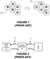
- Figure 1 shows the basic principle of heterogeneous deployments.
- Large macro cells 10 which are geographic areas nominally served by a base station, are generally able to provide coverage to a larger service area.
- micro/pico cells 11 can improve network capacity in certain regions of those macro cells.
- Micro/pico cells are essentially subcells of a macro cell, and are served by low power, short range nodes, such as micro/pico base stations, using frequencies allocated by the macro base station. Allocation of resources between the macro and micro/pico cells can be semi-static, dynamic or shared across the macro-micro/pico layers.
- micro/pico layers One of the main objectives of micro/pico layers is to offload as many users as possible from the macro layers to the micro/pico layers. In an ideal scenario, this may enable users to experience higher data rates in both the macro and micro/pico layers.
- a cell selection offset is an additional power margin for a cell that must be overcome before a handover to the cell will occur. Setting the cell selection offset for a particular microcell to a negative value can therefore increase the probability of a handover occurring to the microcell, thereby extending the range of the microcell.
- Another proposed approach is to increase the transmission power of low power nodes and simultaneously setting appropriately the uplink (UL) power control target P0 for the users connected to low power nodes.
- a remote radio head (RRH) 30 can be used to provide an intermediate node between a user equipment unit (UE) 40 and a base station 20, referred to in this context as a "donor", "serving” or “anchor” base station, as it is providing resources to the RRH 30.
- Communications between the RRH 30 and the UE 40 is performed using the Uu interface, which is the same interface that the UE 40 normally uses to communicate directly to the base station 20.
- the Uu interface which is the same interface that the UE 40 normally uses to communicate directly to the base station 20.
- Document US 2010/255854 A1 may be construed to disclose a method for mitigating interference at a small base station in a hierarchical cell structure.
- the small base station checks a sub-frame allocated to macro user equipment by using a downlink signal received from a macro base station when an interference candidate user equipment list is received.
- the interference candidate user equipment list contains information on the macro user equipment adjacent to a femto cell controlled by the small base station. Then the small base station allocates other sub-frame to femto user equipment located in the femto cell by avoiding the sub-frame allocated to the macro user equipment.
- Embodiments of the present invention are directed to alleviating one or more problems of the prior art.
- some embodiments of the invention may enable more dense coverage within a macro cell while reducing interference that may be experienced by UEs within the macro cell, cell-edge UEs in neighboring macro cells and/or UEs served by pico cells within the macro cell.
- Some examples provide methods of communicating with a selected user equipment terminal (UE) in a first cell served by a base station and a remote radio head.
- the methods include forming a list of non-targeted UEs including other UEs in the first cell and cell edge UEs in a neighboring cell that borders the first cell that are located near a border of the first cell and the neighboring cell, the list including geographic locations and signal to interference plus noise ratios (SINRs) of the non-targeted UEs, generating a list of candidate precoding matrices that can be used to communicate with the selected UE from the base station and/or from the remote radio head, generating a list of available precoding matrices by discarding from the list of candidate precoding matrices those precoding matrices that may cause interference to at least one non-targeted UE, selecting a precoding matrix from the list of available precoding matrices, and communicating with the selected UE using the selected precoding matrix.
- SINRs signal to interference plus
- Discarding precoding matrices from the list of candidate precoding matrices may include discarding from the list of candidate precoding matrices those precoding matrices that generate a beam that causes interference to least one non-targeted UE.
- the methods may further include iteratively generating a list of available precoding matrices and selecting a precoding matrix from the list of available precoding matrices for each UE in the first cell.
- Communicating with the selected UE using the selected precoding matrix may include communicating with the selected UE using the selected precoding matrix by the remote radio head.
- the methods may further include discarding UEs from the list of non-targeted UEs that are served on a different frequency than a frequency on which the targeted UE is served before generating the list of available precoding matrices.
- Local UEs in a central region within the first cell may be served using a first frequency and local UEs in a cell-edge region near a boundary of the first cell with the neighboring cell may be served using a second frequency that is different from the first frequency.
- Cell edge UEs in the neighboring cell may be served using the first frequency or with a third frequency that is different from the second frequency and the first frequency.
- the methods may further include generating a list of picocell UEs served by one or more picocells defined within the first cell, and combining the list of picocell UEs with the list of local UEs in the cell and the list of cell edge UEs to form the combined list of non-targeted UEs.
- Each of the base station, the remote radio head and the targeted UE may include a plurality of antennas.
- the methods may further include discarding UEs from the list of non-targeted UEs that are served on a different resource block than the selected UE.
- Some examples provide a network node in a wireless communication network including a selected user equipment terminal (UE) in a first cell served by the base station and one or more remote radio heads.
- the base station includes a processor that communicates with a plurality of transceivers respective antennas.
- the processor is configured to form a list of non-targeted UEs including other UEs in the first cell and cell edge UEs in a neighboring cell that borders the first cell that are located near a border of the first cell and the neighboring cell, the list including geographic locations and signal to interference plus noise ratios (SINRs) of the non-targeted UEs.
- SINRs signal to interference plus noise ratios
- the processor is further configured to generate a list of candidate precoding matrices that can be used to communicate with the selected UE from the base station and/or from the remote radio head, to discard from the list of candidate precoding matrices those precoding matrices that are likely to cause interference to at least one non-targeted UE to generate a list of available precoding matrices, and to select a precoding matrix from the list of available precoding matrices for communicating with the selected UE.
- the network node may include a base station, and the transceiver may be deployed within the base station.
- the processor may be further configured to discard from the list of candidate precoding matrices those precoding matrices that generate a beam that covers at least one non-targeted UE.
- the processor may be further configured to iteratively generate a list of available precoding matrices and select a precoding matrix from the list of available precoding matrices for each UE in the first cell.
- the processor may be further configured to instruct the remote radio head to communicate with the selected UE using the selected precoding matrix.
- the processor may be further configured to discard UEs from the list of non-targeted UEs that are served on a different frequency than a frequency on which the targeted UE is served before generating the list of available precoding matrices.
- the processor may be further configured to generate a list of picocell UEs served by one or more picocells defined within the first cell, and combine the list of picocell UEs with the list of local UEs in the cell and the list of cell edge UEs to form the combined list of non-targeted UEs.
- the processor may be further configured to discard UEs from the list of non-targeted UEs that are served on a different resource block than the selected UE.
- Some examples provide a computer program product for communicating with a selected user equipment terminal (UE) in a first cell served by a base station and a remote radio head.
- the computer program product includes a tangible computer readable storage medium having computer readable program code embodied in the medium.
- the computer readable program code includes computer readable program code configured to form a list of non-targeted UEs including other UEs in the first cell and cell edge UEs in a neighboring cell that borders the first cell that are located near a border of the first cell and the neighboring cell, the list including geographic locations and signal to interference plus noise ratios (SINRs) of the non-targeted UEs, and computer readable program code configured to generate a list of candidate precoding matrices that can be used to communicate with the selected UE from the base station and/or from the remote radio head.
- SINRs signal to interference plus noise ratios
- the computer program product further includes computer readable program code configured to discard from the list of candidate precoding matrices those precoding matrices that may cause interference to at least one non-targeted UE to generate a list of available precoding matrices, computer readable program code configured to select a precoding matrix from the list of available precoding matrices, and computer readable program code configured to communicate with the selected UE using the selected precoding matrix.
- HetNet heterogeneous networks
- LTE Long Term Evolution
- LTE-Advanced LTE-Advanced
- a heterogeneous network is a radio access network that includes layers of different-sized cells ranging from large (macro cells) to small (microcells, picocells and femtocells). In order to reach the full bandwidth capacity of either protocol, it is thought that operators will need to supplement their traditional large macrocells with many different-sized smaller cells.
- a heterogeneous radio access network typically includes multiple macro and micro cells. Further, in some heterogeneous radio access networks the operation of the macro base stations for the macro cells and micro base stations for the micro cells may be coordinated, particularly in a Coordinated Multipoint (CoMP) system.
- CoMP Coordinated Multipoint
- a collection of cells e.g., the coordinated set of cells
- a central node that coordinates the transmission/reception of user signals to mitigate interference among the smaller sub-cells.
- a multi-cell network is considered herein, where the macro base station in each cell is connected to a given number of remote radio heads (RRHs), which are distributed over the geographic area of the cell.
- a macro base station 20 which may be an eNodeB in LTE parlance, in each cell is equipped with a number (M B ) of antennas, where M B ⁇ 1.
- the macro base station 20 may communicate with a UE 40, which also has a number (N) of antennas, where N ⁇ 1.
- an RRH 30 may communicate with a UE 40.
- the RRH 30 may have a number (M R ) of antennas, where M R ⁇ 1.
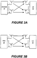
- MIMO for multiple input/multiple output refers to the use of multiple transmitters/receivers at both terminals, such as a base station 20 and a UE 40, as illustrated in Figure 3A .
- both transmitters can transmit independent data streams using the same transmission resources (in time and frequency).
- each of the receivers can separate the data streams and demodulate the transmitted data.
- At least two data streams (referred to in LTE as "layers") may be used.
- the number of layers used in a particular transmission is less than or equal to the number of antennas.
- Precoding is a form of beamforming that supports multi-layer transmission in multi-antenna wireless communications.
- precoding means that multiple data streams are emitted from the transmit antennas with independent and appropriate weightings that are selected so that the link throughput is maximized at the receiver output.
- a precoding matrix is defined that includes weights for each transmit/receive antenna pair.
- the precoding matrix for communications between a macro base station 20 having M B antennas and a UE 40 having N antennas will have dimensions M B x N.
- the precoding matrix for communications between a remote radio head 30 having M R antennas and a UE 40 having N antennas will have dimensions M R x N.
- the macro base station 20 is assumed to have knowledge of the locations of each of the RRHs 30 in its cell.
- the macro base station 20 may also retain control over the precoding matrices (or vectors) used by the RRHs in its cell.
- a generalized system may include K number of RRHs in a cell, where K ⁇ 1.
- K ⁇ 1.
- each RRH is equipped with the same number of antennas, denoted by M R , where M R ⁇ 1.
- M R the number of antennas
- the user equipment (UEs) are assumed to have N antennas each, where N ⁇ 1, and can receive coordinated transmission (involving one or more layers) from multiple RRHs as well as the macro base station in their respective cells.
- the assignment of precoding matrices is coordinated with the selection of remote radio heads (RRHs) for transmission to selected UEs in a heterogeneous deployment to increase aggregate cell throughput while reducing interference to neighboring cells.
- RRHs remote radio heads
- the assignment of precoding matrices and the selection of RRHs may be coordinated with fractional frequency reuse (FFR) in the macro network to further mitigate interference between neighboring cells.
- FFR fractional frequency reuse
- these approaches may be extended to networks that include picocell overlays of the macro network.
- the macro base station may coordinate with the picocells to mitigate additional interference.
- each macro base station 20 may have knowledge of the location of the UEs 40 in its own cell, as well as the locations of the UEs 40 in neighboring cells that are located near the cell boundary, and in some embodiments the locations of UEs 40 in picocells within the macro cell.
- the identities of cell-edge UEs 40 in neighboring cells can be determined using an appropriate metric, such as one based on signal to interference plus noise ratio (SINR).
- SINR signal to interference plus noise ratio
- UEs are able to estimate their locations using global positioning system (GPS) technology in the case of 4G (and beyond) UEs, and 3GPP-standardized positioning reference signals (PRS) in the case of pre-4G UEs.
- GPS global positioning system
- PRS 3GPP-standardized positioning reference signals
- This information is fed back by the UE to its serving base station.
- the serving base station may share the locations of its cell-edge UEs with its neighboring base stations.
- the location information need not be highly accurate; a coarse quantization may be sufficient.
- the frequency of location-related signaling between neighboring base stations need not be very high, because the interval between significant changes in UE location may be much larger than the duration of a radio frame.
- Embodiments of the invention that utilize coordinated precoding matrix and RRH selection are illustrated in Figure 4 .
- two distinct sets of precoding matrices are considered.
- the first set contains matrices of size M B xL, where L is the number of transmission layers used for communication with a UE.
- the rows of these matrices correspond to the transmit antennas of the macro base station 20.
- the second set contains matrices of size M R xL, the rows of which correspond to the antennas of each RRH 30.
- Both sets also contain the appropriately sized all-zero matrices, which corresponds to the scenario where the macro base station or the RRH is not transmitting to a given UE.
- the distinction between the matrices in the two sets is (1) the difference between the number of antennas at the macro base station (M B ) and the number of antennas at each RRH (M R ), and (2) the fact that the directional transmission of the macro base station 20 is restricted such that the beam that is formed points within the coverage area of the cell, where as the beam formed by each RRH 30 has no such restrictions.
- the precoding matrices that are used for transmission to the UEs in each cell are of the size (M B +KM R )xL, and are comprised of candidate matrices from each of the two sets described above. Iterating through all combinations of the matrices in the two sets to form different precoding matrices yields the transmission codebook used in each of the cells. Noting that a subset of the precoding matrices contain all-zero sub-matrices, the codebook addresses the scenario in which only a subset of the available RRHs 30 transmit to a particular UE (i.e., selective transmission).
- the scenario in which the antennas of the macro base station 20 are not used for transmission to a particular UE is also covered by the matrices in the codebook.
- an appropriate selection of precoding matrices is made to mitigate both intra-cell and inter-cell interference.
- a precoding matrix is selected such that the transmission to the intended UE is spatially uncorrelated with respect to the channels of other UEs in the same cell that are chosen to be served in the same resource block (RB), i.e. that use the same time/frequency resources.
- the precoding matrix is selected such that the transmission to the intended UE is spatially uncorrelated with respect to the channels of cell-edge UEs in neighboring cells. This is facilitated by the knowledge of the location of the UEs and RRHs 30, which is available at the serving macro base station 20.
- each beam has a unique reference signal (RS) that is broadcast.
- RS reference signal
- the UE measures its SINR with respect to each of these RSs and feed this information back to the base station.
- the base station can then determine if a particular UE is in the beam formed by the precoding matrix based on whether the SINR value is above a pre-defined threshold.
- the macro base station 20 iterates through the available precoding matrices. For each precoding matrix, the macro base station 20 may utilize the latest available locations of the UE 40 and RRH 30 to determine if any UE other than the intended receiver is in the immediate path of the beam(s) that will be formed using the matrix in question. If this is the case, that matrix may be discarded from consideration.
- a precoding matrix from the remaining subset is chosen using an appropriate set of criteria. The chosen precoding matrix is used to serve the UE 40 until a newer set of UE locations is available. This process may be repeated routinely at pre-defined intervals and/or via an interrupt-driven approach.
- the operations identify a precoding matrix for use with communications with a UE in a cell that may reduce or minimize the impact on other UEs in the cell and cell-edge UEs in neighboring cell.
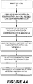
- a UE in the cell is selected for consideration (block 80).
- the operations include forming a list of non-targeted UEs, which includes other UEs in the cell and cell-edge UEs in the neighboring cells (block 82). Geographic locations and signal to interference plus noise ratios (SINRs) of the non-targeted UEs are also obtained.
- SINRs signal to interference plus noise ratios
- a combined list of other UEs in the cell and cell edge UEs in the neighboring cell is compiled to provide a combined list of non-targeted UEs.
- the operations then generate a list of candidate precoding matrices that can be used to communicate with the selected UE from the base station and/or from one or more remote radio heads in the cell (block 84).
- a list of available precoding matrices is then generated by discarding from the list of candidate precoding matrices those precoding matrices that may cause interference to at least one non-targeted UE (block 86).
- a precoding matrix is then selected from the list of available precoding matrices (block 88), and the selected precoding matrix is then used for communicating with the selected UE (block 90).
- Figure 4B illustrates a collection of cells 10A, 10B, 10C that are served by respective macro base stations 20A, 20B, 20C, and in which a plurality of RRHs 30 are deployed.
- a plurality of UEs 40A to 40F operate in the cells.
- the base station codebooks include precoding matrices B1-B3 utilized by base station 20A, precoding matrices B4-B6 utilized by base station 20B, and precoding matrices B7-B9 utilized by base station 20C.
- the RRH codebooks include precoding matrices R1-R5.
- the macro base station 20A may communicate with UE 40D using precoding matrix B1, while precoding matrix R5 may be used by an RRH in cell 10A to communicate with UE 40C.
- precoding matrix R3 may be used by RRH 30B or precoding matrix R4 may be used by RRH 30A to communicate with UE 40A.
- precoding matrix B4 may not be available for communications with UE 40A from the base station 20B, because the UE 40B in cell 10B may be in the path of the beam formed by precoding matrix B4.
- the precoding matrix R5 may not be usable by RRH 30C to communicate with UE 40B, because the UE 40C in cell 10A may be in the path of the beam formed by precoding matrix R5.
- precoding matrices B9, R1, R2 and R3 may be available for the illustrated UEs, while precoding matrices R4 and R5 may be unavailable for the illustrated UEs.
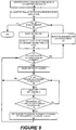
- a list of all UE locations in the cell 10 served by the base station 20 is generated or otherwise obtained along with a list of all available precoding matrices (block 100). Values of signal to interference plus noise ratios (SINRs) may also be obtained for each UE in the cell.
- SINRs signal to interference plus noise ratios
- the macro base station 20 also obtains information about the locations and SINRs of cell-edge UEs in neighboring cells by exchanging UE location information with the base stations 20 that serve the neighboring cells (block 102).
- the macro base station 20 selects a precoding matrix for each UE in the cell.
- the macro base station may check to see if all UEs in the cell have been considered and precoding matrices selected for each UE in the cell (block 104). Once precoding matrices have been selected for each UE in the cell, the process ends, and the precoding matrices are used for transmission to the UEs served by the base station. If all UEs have not been considered, the macro base station 20 selects the next UE in the cell (block 106) and then determines if all precoding matrices for the selected UE have been considered (block 108).
- a precoding matrix is selected from the group of candidate precoding matrices for use with the selected UE (block 116), and operations return to block 104 to determine if all UEs in the cell have been considered.
- non-targeted UE refers to all UEs in the cell served by the macro base station 20 other than the selected UE that is being considered, along with all cell-edge UEs in neighboring cells.
- the operations select the next non-targeted UE (block 114) and determine if the selected non-targeted UE is subject to interference from the selected precoding matrix, for example if the non-targeted UE in question is in the path of a beam formed to the selected UE by the selected precoding matrix (block 118). If the non-targeted UE is in the path of the beam formed by the selected precoding matrix, the selected precoding matrix is dropped from the list of candidate precoding matrices that are available to be used for communications with the selected UE (block 120). Otherwise, operations return to block 112 to determine if any other non-targeted UEs remain for consideration.
- FIG. 6 a scenario is illustrated in which two cell-interior UEs 40A, 40B are to be served over the same resource block (RB) by base stations 20A, 20B in one of two adjacent cells 10A, 10B. Since both UEs 40A, 40B are relatively isolated from the transmission in the neighboring cells (assuming reasonable transmit power levels), the macro base station 20A, 20B in each cell could be used to serve its respective UE. In practice, one or more RRHs 30 could also be chosen to transmit to these UEs in addition to the base station. Using a selected precoding matrix, the macro base station 20A in cell 10A would form a beam in the direction of the intended UE 40A. The power from this directional transmission would potentially propagate into the neighboring cell 10B. However, this would be acceptable if only a cell-interior UE is being served in the neighboring cell 10B as illustrated in Figure 6 .
- RB resource block
- Figure 7 illustrates a scenario similar to that illustrated in Figure 6 , except that there is a cell-edge UE 40C in the neighboring cell 10B (or in the same cell 10A) that is in the path of the directional beam formed by the macro base station 20A towards the UE 40A.
- an alternate precoding matrix can be selected such that either a different beam is formed from the macro base station 20A to serve the desired UE 40A without affecting the performance of the cell-edge UE 40C, or the antennas of the macro base station 20A are not selected for transmission altogether.
- one or more RRHs 30A, 30B may be chosen to serve the UE 40A by forming a beam that is spatially uncorrelated with the cell-edge UE 40C using, for example, precoding matrix R3 or R4 as illustrated in Figure 7 .
- precoding matrix R3 or R4 as illustrated in Figure 7 .
- a distributed placement of the RRHs 30 over the cell area may be particularly useful in this scenario as it may potentially provide a variety of candidate precoding matrices that can be selected.
- Figure 8 illustrates a scenario in which a cell-edge UE 40A, 40B is to be served in each of two neighboring cells 10A, 10B.
- these two cell-edge UEs 40A, 40B are located relatively closely to each other.
- one or more RRHs 30 would be suitably chosen to serve the UE 40A, 40B in the respective cell.
- the individual precoding matrices of these RRHs may be selected such that the beams formed by these RRHs 30 may not substantially impact the cell-edge UE 40A, 40B in the neighboring cell. If this is not possible for a given RRH, then a different RRH may be selected instead.
- precoding matrix R1 may be selected for transmission by RRH 30C to UE 40A
- precoding matrix R2 may be selected for transmission by RRH 30A to UE 40B
- Precoding matrices for transmission by RRHs 30B and 30D may be rejected from consideration based on the arrangement of the UEs 40A, 40B.
- the precoding matrix selection and assignment operations described above may be coupled with a Fractional Frequency Reuse (FFR) scheme in the macro network.
- FFR Fractional Frequency Reuse
- Such a coupling is motivated by the fact that there may be instances in which the number of spatial degrees of freedom provided by the techniques described above may be insufficient.
- a decision could be made to not serve the intended UE altogether.
- neither of these solutions is likely to be beneficial in terms of cell-edge and aggregate throughputs.
- the macro base stations can coordinate the frequency utilized for cell-edge communication in their respective cells.
- the RRHs that are chosen to transmit to cell-edge UEs in each cell can be instructed to transmit on a frequency that is orthogonal to or otherwise distinct from the frequency used by their counterparts in neighboring cells to transmit to cell-edge UEs. This approach may partially alleviate the restrictions on the precoding matrices that can be selected for transmission.
- a precoding matrix need not be discarded from consideration if the corresponding beam points in the direction of the cell-edge UE 40C. This is because the cell-edge UE 40C will be served using a different frequency than the UE 40A in the interior of cell 10A.
- Example 8 In another example, consider the scenario in Example 8. Using FFR coordination, from the standpoint of the base station 10A, the precoding matrices that correspond to beams that point in the direction of the cell-edge UE 40B in the neighboring cell 10B would no longer need to be rejected from consideration since the UE 40B will be served using a different frequency than the UE 40A in the cell 10A. Furthermore, as in the case of conventional FFR, a pre-determined set of frequencies can be reused by the macro base station and RRHs transmitting to cell-interior UEs in any of the cells.
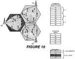
- each base station 20A, 20B, 20C may use a first frequency, or frequency range/band, for transmissions to UEs located within the interior of their respective cells 10A, 10B, 10C.
- each base station 20A, 20B, 20C may use a different frequency.
- base station 20A may use a second frequency or frequency range/band F2 for transmission to UEs located near the edge of cell 10A
- base station 20B may use a third frequency or frequency range/band F3 for transmission to UEs located near the edge of cell 10B
- base station 20C may use a fourth frequency or frequency range/band F4 for transmission to UEs located near the edge of cell 10C.
- the system model described above may be extended to include picocells that are overlaid on the macro network. It is important to note that due to the relatively small geographic coverage area of a picocell, the extended technique utilized in this embodiment may be more sensitive to inaccuracies in the UE location information than the previous embodiments. As a result, to maintain the effectiveness of the technique, it may be desirable to increase the frequency of UE location information exchange between a pico base station and macro base station, and also between neighboring macro base stations.
- the macro base station may routinely request knowledge of the location of the UEs that are being served by the pico base station. Then, during the precoding matrix selection process for a particular UE in the macro network, the subset of the UEs that are being served using the same frequency in the pico network would be appended to the existing set of macro-network UEs to whom interference is to be mitigated. The rest of the algorithm from the previous embodiments is unchanged.
- the corresponding macro base station may share its location with its neighboring counterparts, in addition to the locations of its own macro network cell-edge UEs.
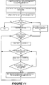
- FIG. 11 This embodiment is illustrated in the flowchart of Figure 11 , which is similar to the flowchart of Figure 5 except that a new block 103 is added.
- block 103 a list of UEs served by picocells within the macro cell is obtained and appended to the list of target UEs that are considered in the selection of precoding matrices to be used for transmissions to UEs within the macro cell.
- UEs located within picocells are considered in a similar manner as cell-edge UEs in adjacent cells for purposes of selecting precoding matrices.
- This embodiment can also incorporate coupling of the precoding assignment with Fractional Frequency Reuse (FFR) to increase potential orthogonal assignments as is described in connection with Figures 9-10 .
- FFR Fractional Frequency Reuse
- the FFR assignment for a picocell can be chosen, for example, to be the same as the cell-interior FFR assignment if the picocell is overlaid in the cell-edge area, or to be the same as the cell edge FFR assignment if the pico is overlaid in the cell-interior region.
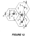
- picocells 60A, 60B and 60C are defined within macro cells 10A, 10B and 10C.
- a UE 40D is active in picocell 60A (which straddles the boundary between macro cell 10A and macro cell 10C), and a UE 40C is active in picocell 60B in macro cell 10A.
- the base station 20A chooses a precoding matrix for transmissions to UE 40A in cell 10A, the base station 20A will append a list of UEs in picocells that overlap cell 10A to the list of target UEs that are considered for interference purposes.
- a precoding matrix for transmissions to UE 40A may be removed from consideration if it would result in unacceptable interference to UE 40D in the pico cell 60A.
- the base station 20B chooses a precoding matrix for transmissions to UE 40B in cell 10B, the base station 20B will append a list of UEs in picocells that overlap cell 10B to the list of target UEs that are considered for interference purposes.
- a precoding matrix for transmissions to UE 40B may be removed from consideration if it would result in unacceptable interference to UE 40C in the pico cell 60B.
- the base station 600 typically includes a base station processor 601 coupled to a plurality of transceivers 602A-602N, and network interface 604. Each transceiver 602A-602N is coupled to a respective antenna 605A-605N.
- the base station processor 601 will typically perform the above described methods and algorithms for a predetermined macro cell.
- a base station controller 607 will interact with one or more base stations 600 when there is a need to control the overall operation of the network.
- the base station processor 601 would typically have the necessary functionality and procedures for processing between the media access control and physical layers of both transmission and reception signals.
- the base station controller 607 in conjunction with the base station 600 is used to provide the necessary beam forming techniques described herein.
- the remote radio head700 typically includes a relay node processor 701 coupled to a plurality of transceivers 702A-702N, each of which includes a respective antenna 705A-705N.
- the remote radio headprocessor 701 will typically perform the above described methods and algorithms for a predetermined microcell.
- the remote radio headprocessor 701 includes the necessary functionality and procedures for processing between the media access control and physical layers of both transmission and reception signals.
- the remote radio headprocessor 701 is also configured to provide the necessary beam forming techniques described herein.
- Some embodiments of the inventive concepts described herein may enable high cell-edge data rates to be realized by combining existing deployments with selective scheduling of RRHs and assignment of precoding matrices and fractional frequency reuse.
- some embodiments may also help mitigate additional interference through coordination with the pico base stations.
- micro/pico cells and micro/pico base stations and their respective locations within or near the macro cell are not limiting, since a macro cell could encompass one or more than the illustrated micro/pico cells and such micro/pico cells may be diversely and non-uniformly arranged from one macro cell to another, depending upon geographic utilization and traffic need and conditions.
- micro base station is to be understood as broadly encompassing any type of station which operates over a radio or air interface on both downlink (DL) and uplink (UL) and has extent of transmission that is lesser than (e.g., in geographic range or power) or subordinate to (e.g., delegated from/by) a macro base station.
- micro cell refers to any cellular territory or coverage area served by such broadly defined micro base station.
- Examples of types of cells and base stations encompassed by the terminology “micro cell” and “micro base station” also include pico cells and pico base stations, femto cells (which can exist in a femto cluster) and femto base stations, and relay base stations.
- Small base stations mainly means base stations transmitting with lower power and with fewer processing/hardware capacities than the normal macro base stations.
- the functional blocks may include or encompass, without limitation, digital signal processor (DSP) hardware, reduced instruction set processor, hardware (e.g., digital or analog) circuitry including but not limited to application specific integrated circuit(s) [ASIC], and (where appropriate) state machines capable of performing such functions.
- DSP digital signal processor
- ASIC application specific integrated circuit
- a computer is generally understood to comprise one or more processors or one or more controllers, and the terms computer and processor and controller may be employed interchangeably herein.
- the functions may be provided by a single dedicated computer or processor or controller, by a single shared computer or processor or controller, or by a plurality of individual computers or processors or controllers, some of which may be shared or distributed.
- processor or “controller” shall also be construed to refer to other hardware capable of performing such functions and/or executing software, such as the example hardware recited above.
Landscapes
- Engineering & Computer Science (AREA)
- Computer Networks & Wireless Communication (AREA)
- Signal Processing (AREA)
- Mobile Radio Communication Systems (AREA)
Claims (15)
- Procédé de communication avec un terminal d'équipement utilisateur, UE, sélectionné (40) dans une première cellule (10A, 10B, 10C) desservie par une station de base (20A, 20B, 20C, 600) et une tête radio distante (30A, 30B, 30C, 700), le procédé comprenant :la formation (82) d'une liste d'UE non ciblés incluant d'autres UE dans la première cellule et des UE de bord de cellule (40C) dans une cellule voisine (10A) qui borde la première cellule lesquels se trouvent près d'une bordure de la première cellule et de la cellule voisine, la liste incluant des emplacements géographiques et des rapports signal-bruit plus interférence, SINR, des UE non ciblés ;la génération (84) d'une liste de matrices de précodage candidates qui peuvent être utilisées pour communiquer avec l'UE sélectionné à partir de la station de base et/ou à partir de la tête radio distante ;la génération (86) d'une liste de matrices de précodage disponibles en éliminant, de la liste de matrices de précodage candidates, ces matrices de précodage qui peuvent causer une interférence à au moins un UE non ciblé sur la base des emplacements géographiques et des SINR des UE non ciblés ;la sélection (88) d'une matrice de précodage dans la liste de matrices de précodage disponibles ; etla communication (90) avec l'UE sélectionné en utilisant la matrice de précodage sélectionnée.
- Procédé selon la revendication 1, dans lequel :- l'élimination de matrices de précodage de la liste de matrices de précodage candidates comprend l'élimination, de la liste de matrices de précodage candidates, de ces matrices de précodage qui génèrent un faisceau qui causent une interférence à au moins un UE non ciblé ; ou- le procédé comprend en outre la génération par itération d'une liste de matrices de précodage disponibles et la sélection d'une matrice de précodage dans la liste de matrices de précodage disponibles pour chaque UE dans la première cellule ; ou- la communication avec l'UE sélectionné en utilisant la matrice de précodage sélectionnée comprend la communication avec l'UE sélectionné en utilisant la matrice de précodage sélectionnée par la tête radio distante.
- Procédé selon la revendication 1, comprenant en outre l'élimination des UE de la liste d'UE non ciblés qui sont desservis sur une fréquence différente d'une fréquence sur laquelle l'UE ciblé est desservi avant génération de la liste de matrices de précodage disponibles.
- Procédé selon la revendication 3, dans lequel des UE locaux dans une région centrale au sein de la première cellule sont desservis en utilisant une première fréquence et où des UE locaux dans une région de bord de cellule près d'une limite de la première cellule avec la cellule voisine sont desservis en utilisant une deuxième fréquence qui est différente de la première fréquence.
- Procédé selon la revendication 4, dans lequel des UE de bord de cellule dans la cellule voisine sont desservis en utilisant une troisième fréquence qui est différente de la deuxième fréquence et de la première fréquence.
- Procédé selon la revendication 1, dans lequel- le procédé comprend en outre la génération d'une liste d'UE de picocellule desservis par une ou plusieurs picocellules définies au sein de la première cellule, et la combinaison de la liste d'UE de picocellule avec la liste d'UE locaux dans la cellule et la liste d'UE de bord de cellule pour former la liste combinée d'UE non ciblés ; ou- chacune de la station de base, chacun de la tête radio distante et de l'UE ciblé inclut une pluralité d'antennes (605, 705) ; ou- le procédé comprend en outre l'élimination des UE de la liste d'UE non ciblés qui sont desservis sur un bloc de ressource différent de l'UE sélectionné.
- Produit programme informatique pour communiquer avec un terminal d'équipement utilisateur, UE, sélectionné (40) dans une première cellule (10A, 10B, 10C) desservie par une station de base (20A, 20B, 20C) et une tête radio distante (30A, 30B, 30C), le produit programme informatique comprenant :
un support de stockage lisible par ordinateur ayant un code de programme lisible par ordinateur incorporé dans le support, le code de programme lisible par ordinateur configurant un processeur (601, 701) pour mettre en oeuvre toutes les étapes d'un procédé selon l'une quelconque des revendications de procédé précédentes. - Station de base (20A, 20B, 20C, 600) dans un réseau de communication sans fil incluant un terminal d'équipement utilisateur, UE, sélectionné (40) dans une première cellule (10A, 10B, 10C) desservie par la station de base et une ou plusieurs têtes radio distantes (30A, 30B, 30C), comprenant :
un processeur (601) couplé à une pluralité d'émetteurs-récepteurs (602) ayant des antennes respectives (605), dans laquelle le processeur est configuré pour :- former une liste d'UE non ciblés incluant d'autres UE dans la première cellule (10B) et des UE de bord de cellule (40C) dans une cellule voisine (10A) qui borde la première cellule lesquels se trouvent près d'une bordure de la première cellule et de la cellule voisine, la liste incluant des emplacements géographiques et des rapports signal-bruit plus interférence, SINR, des UE non ciblés,- générer une liste de matrices de précodage candidates qui peuvent être utilisées pour communiquer avec l'UE sélectionné à partir de la station de base et/ou à partir de la tête radio distante,- éliminer, de la liste de matrices de précodage candidates, ces matrices de précodage qui sont susceptibles de causer une interférence à au moins un UE non ciblé pour générer une liste de matrices de précodage disponibles sur la base d'emplacements géographiques et de SINR des UE non ciblés, et- sélectionner une matrice de précodage dans la liste de matrices de précodage disponibles pour communiquer avec l'UE sélectionné. - Station de base selon la revendication 8, dans laquelle le processeur est en outre configuré pour éliminer, de la liste de matrices de précodage candidates, ces matrices de précodage qui génèrent un faisceau qui couvre au moins un UE non ciblé.
- Station de base selon la revendication 8, dans laquelle le processeur est en outre configuré pour générer par itération une liste de matrices de précodage disponibles et sélectionner une matrice de précodage dans la liste de matrices de précodage disponibles pour chaque UE dans la première cellule.
- Station de base selon la revendication 8, dans laquelle le processeur est en outre configuré pour indiquer à la tête radio distante de communiquer avec l'UE sélectionné en utilisant la matrice de précodage sélectionnée.
- Station de base selon la revendication 8, dans laquelle le processeur est en outre configuré pour éliminer des UE de la liste d'UE non ciblés qui sont desservis sur une fréquence différente d'une fréquence sur laquelle l'UE ciblé est desservi avant génération de la liste de matrices de précodage disponibles.
- Station de base selon la revendication 12, dans laquelle des UE locaux dans une région centrale au sein de la première cellule sont desservis en utilisant une première fréquence et où des UE locaux dans une région de bord de cellule près d'une limite de la première cellule avec la cellule voisine sont desservis en utilisant une deuxième fréquence qui est différente de la première fréquence.
- Station de base selon la revendication 13, dans laquelle des UE de bord de cellule dans la cellule voisine sont desservis en utilisant une troisième fréquence qui est différente de la deuxième fréquence et de la première fréquence.
- Station de base selon la revendication 8, dans laquelle :- le processeur est en outre configuré pour générer une liste d'UE de picocellule desservis par une ou plusieurs picocellules définies au sein de la première cellule, et combiner la liste d'UE de picocellule avec la liste d'UE locaux dans la cellule et la liste d'UE de bord de cellule pour former la liste combinée d'UE non ciblés ; ou- le processeur est en outre configuré pour éliminer les UE de la liste d'UE non ciblés qui sont desservis sur un bloc de ressource différent de l'UE sélectionné.
Applications Claiming Priority (2)
| Application Number | Priority Date | Filing Date | Title |
|---|---|---|---|
| US13/647,753 US8792896B2 (en) | 2012-10-09 | 2012-10-09 | Beamforming for increasing cell edge capacity in a heterogeneous network |
| PCT/IB2013/002194 WO2014057329A2 (fr) | 2012-10-09 | 2013-10-03 | Formation de faisceau pour augmenter la capacité de bords de cellules dans un réseau hétérogène |
Publications (2)
| Publication Number | Publication Date |
|---|---|
| EP2907245A2 EP2907245A2 (fr) | 2015-08-19 |
| EP2907245B1 true EP2907245B1 (fr) | 2019-07-10 |
Family
ID=49886985
Family Applications (1)
| Application Number | Title | Priority Date | Filing Date |
|---|---|---|---|
| EP13815120.4A Active EP2907245B1 (fr) | 2012-10-09 | 2013-10-03 | Formation de faisceau pour augmenter la capacité de bords de cellules dans un réseau hétérogène |
Country Status (3)
| Country | Link |
|---|---|
| US (1) | US8792896B2 (fr) |
| EP (1) | EP2907245B1 (fr) |
| WO (1) | WO2014057329A2 (fr) |
Families Citing this family (20)
| Publication number | Priority date | Publication date | Assignee | Title |
|---|---|---|---|---|
| JP5783325B2 (ja) * | 2011-05-06 | 2015-09-24 | 富士通株式会社 | ユーザー設備、基地局、リモート無線ヘッドの選択方法 |
| KR101922597B1 (ko) * | 2011-12-27 | 2019-02-21 | 삼성전자주식회사 | Fdd 모드로 동작하는 거대 mimo 시스템에서 채널상태정보 기준신호를 전송하고 수신하기 위한 송수신 장치 및 방법 |
| US9275690B2 (en) | 2012-05-30 | 2016-03-01 | Tahoe Rf Semiconductor, Inc. | Power management in an electronic system through reducing energy usage of a battery and/or controlling an output power of an amplifier thereof |
| US9001680B2 (en) * | 2012-07-16 | 2015-04-07 | Broadcom Corporation | Method and apparatus for providing improved detection of overlapping networks |
| US9509351B2 (en) | 2012-07-27 | 2016-11-29 | Tahoe Rf Semiconductor, Inc. | Simultaneous accommodation of a low power signal and an interfering signal in a radio frequency (RF) receiver |
| KR20140072968A (ko) * | 2012-12-05 | 2014-06-16 | 한국전자통신연구원 | 이동 통신 시스템에서 다중 연결을 이용한 단말의 핸드오버 방법 |
| US9166663B2 (en) * | 2012-12-14 | 2015-10-20 | Futurewei Technologies, Inc. | System and method for open-loop MIMO communications in a SCMA communications system |
| US8948747B2 (en) | 2013-02-13 | 2015-02-03 | The Boeing Company | Overlapping cells for wireless coverage |
| US9531070B2 (en) | 2013-03-15 | 2016-12-27 | Christopher T. Schiller | Extending beamforming capability of a coupled voltage controlled oscillator (VCO) array during local oscillator (LO) signal generation through accommodating differential coupling between VCOs thereof |
| US9666942B2 (en) | 2013-03-15 | 2017-05-30 | Gigpeak, Inc. | Adaptive transmit array for beam-steering |
| US9780449B2 (en) | 2013-03-15 | 2017-10-03 | Integrated Device Technology, Inc. | Phase shift based improved reference input frequency signal injection into a coupled voltage controlled oscillator (VCO) array during local oscillator (LO) signal generation to reduce a phase-steering requirement during beamforming |
| US9722310B2 (en) | 2013-03-15 | 2017-08-01 | Gigpeak, Inc. | Extending beamforming capability of a coupled voltage controlled oscillator (VCO) array during local oscillator (LO) signal generation through frequency multiplication |
| US9184498B2 (en) | 2013-03-15 | 2015-11-10 | Gigoptix, Inc. | Extending beamforming capability of a coupled voltage controlled oscillator (VCO) array during local oscillator (LO) signal generation through fine control of a tunable frequency of a tank circuit of a VCO thereof |
| US9837714B2 (en) | 2013-03-15 | 2017-12-05 | Integrated Device Technology, Inc. | Extending beamforming capability of a coupled voltage controlled oscillator (VCO) array during local oscillator (LO) signal generation through a circular configuration thereof |
| US9716315B2 (en) | 2013-03-15 | 2017-07-25 | Gigpeak, Inc. | Automatic high-resolution adaptive beam-steering |
| JP2015185956A (ja) * | 2014-03-20 | 2015-10-22 | 株式会社Nttドコモ | ユーザ装置及び基地局 |
| US9615263B2 (en) * | 2015-05-27 | 2017-04-04 | Telefonaktiebolaget L M Ericsson (Publ) | Method to improve the performance in cell range expansion using location based codebook subset restriction |
| WO2017002145A1 (fr) * | 2015-06-30 | 2017-01-05 | Nec Corporation | Station de base, système de communication, procédé et programme |
| US10887861B2 (en) | 2015-07-20 | 2021-01-05 | At&T Intellectual Property I, L.P. | Facilitating harmonization of wireless communication service delivery |
| CN111246485B (zh) * | 2020-02-27 | 2022-09-20 | 华南理工大学 | 一种高密度车载通信环境下的车联网资源分配方法 |
Family Cites Families (4)
| Publication number | Priority date | Publication date | Assignee | Title |
|---|---|---|---|---|
| US7353034B2 (en) * | 2005-04-04 | 2008-04-01 | X One, Inc. | Location sharing and tracking using mobile phones or other wireless devices |
| US8086237B2 (en) * | 2007-11-09 | 2011-12-27 | United States Cellular Corporation | Efficient neighbor list creation for cellular networks |
| US8140098B2 (en) | 2008-05-15 | 2012-03-20 | Qualcomm Incorporated | Spatial interference mitigation for wireless communication |
| US8145223B2 (en) | 2009-04-09 | 2012-03-27 | Telefonaktiebolaget L M Ericsson (Publ) | Inter-cell interference mitigation |
-
2012
- 2012-10-09 US US13/647,753 patent/US8792896B2/en active Active
-
2013
- 2013-10-03 WO PCT/IB2013/002194 patent/WO2014057329A2/fr not_active Ceased
- 2013-10-03 EP EP13815120.4A patent/EP2907245B1/fr active Active
Non-Patent Citations (1)
| Title |
|---|
| None * |
Also Published As
| Publication number | Publication date |
|---|---|
| WO2014057329A2 (fr) | 2014-04-17 |
| US8792896B2 (en) | 2014-07-29 |
| US20140099960A1 (en) | 2014-04-10 |
| EP2907245A2 (fr) | 2015-08-19 |
| WO2014057329A3 (fr) | 2014-05-30 |
Similar Documents
| Publication | Publication Date | Title |
|---|---|---|
| EP2907245B1 (fr) | Formation de faisceau pour augmenter la capacité de bords de cellules dans un réseau hétérogène | |
| JP6712791B2 (ja) | 基地局、通信方法及び集積回路 | |
| Geraci et al. | Understanding UAV cellular communications: From existing networks to massive MIMO | |
| US10932234B2 (en) | System and method for time division duplexed multiplexing in transmission-reception point to transmission-reception point connectivity | |
| EP2638726B1 (fr) | Procédé et noeud de réseau pour la configuration de motifs de transmission de sous-trames presque silencieuses pour réduire l'interférence intercellulaire dans un système de radiocommunication cellulaire | |
| EP2679058B1 (fr) | Configuration de la distribution de puissance dans les zones de coopération de réseaux de communications cellulaires | |
| US9781728B2 (en) | Method and apparatus for coordinating schedulers in a coordinated multi-point communication system | |
| JP6034500B2 (ja) | モバイルリレーノードからヘテロジーニアスネットワークへの干渉の軽減 | |
| KR101207570B1 (ko) | 셀 간 간섭 완화 방법 | |
| US9264912B2 (en) | Fractional frequency re-use and beamforming in relay nodes of a heterogeneous network | |
| US9570815B2 (en) | Antenna apparatus and method for handover using the same | |
| JP2018011347A (ja) | セル間の干渉を管理または改善すること | |
| US20090286465A1 (en) | Scheduling methods and systems for multi-hop relay in wireless communications | |
| JP2009033717A (ja) | リソース割当方法及び通信装置 | |
| JP2013516799A (ja) | ダウンリンクマルチアンテナマルチ基地局干渉協調方法と基地局 | |
| Georgakopoulos et al. | Coordination multipoint enabled small cells for coalition-game-based radio resource management | |
| US9584194B2 (en) | Method and apparatus for cancelling interference | |
| US8918113B2 (en) | Wireless communication network with noise metric based optimization for cellular capacity improvement | |
| EP3035755A1 (fr) | Procédé de rapport de rétroaction de canal dans un système de communication radio, procédé de détermination d'un ensemble de stations mobiles à programmer dans un système de communication radio, programme informatique, station mobile et appareil de programmation de celui-ci | |
| Jie et al. | A CoMP-Based outage compensation solution for heterogeneous femtocell networks | |
| Baracca et al. | Improving eICIC with coordinated beamforming and scheduling in co-channel HetNets | |
| Noh et al. | Distributed frequency resource control for intercell interference control in heterogeneous networks | |
| Li | Downlink resource allocation in cooperative wireless networks | |
| RU2575702C2 (ru) | Способы и сетевые узлы для конфигурации шаблонов передачи почти пустого подкадра и соответствующих шаблонов измерений для снижения помех между сотами в гетерогенной системе сотовой радиосвязи |
Legal Events
| Date | Code | Title | Description |
|---|---|---|---|
| PUAI | Public reference made under article 153(3) epc to a published international application that has entered the european phase |
Free format text: ORIGINAL CODE: 0009012 |
|
| 17P | Request for examination filed |
Effective date: 20150330 |
|
| AK | Designated contracting states |
Kind code of ref document: A2 Designated state(s): AL AT BE BG CH CY CZ DE DK EE ES FI FR GB GR HR HU IE IS IT LI LT LU LV MC MK MT NL NO PL PT RO RS SE SI SK SM TR |
|
| AX | Request for extension of the european patent |
Extension state: BA ME |
|
| RIN1 | Information on inventor provided before grant (corrected) |
Inventor name: BOUDREAU, GARY, DAVID Inventor name: AHMAD, TALHA |
|
| DAX | Request for extension of the european patent (deleted) | ||
| REG | Reference to a national code |
Ref country code: DE Ref legal event code: R079 Ref document number: 602013057723 Country of ref document: DE Free format text: PREVIOUS MAIN CLASS: H04B0007020000 Ipc: H04B0007022000 |
|
| GRAP | Despatch of communication of intention to grant a patent |
Free format text: ORIGINAL CODE: EPIDOSNIGR1 |
|
| STAA | Information on the status of an ep patent application or granted ep patent |
Free format text: STATUS: GRANT OF PATENT IS INTENDED |
|
| RIC1 | Information provided on ipc code assigned before grant |
Ipc: H04B 7/06 20060101ALI20190415BHEP Ipc: H04W 36/30 20090101ALI20190415BHEP Ipc: H04B 7/022 20170101AFI20190415BHEP |
|
| GRAS | Grant fee paid |
Free format text: ORIGINAL CODE: EPIDOSNIGR3 |
|
| INTG | Intention to grant announced |
Effective date: 20190508 |
|
| GRAA | (expected) grant |
Free format text: ORIGINAL CODE: 0009210 |
|
| STAA | Information on the status of an ep patent application or granted ep patent |
Free format text: STATUS: THE PATENT HAS BEEN GRANTED |
|
| AK | Designated contracting states |
Kind code of ref document: B1 Designated state(s): AL AT BE BG CH CY CZ DE DK EE ES FI FR GB GR HR HU IE IS IT LI LT LU LV MC MK MT NL NO PL PT RO RS SE SI SK SM TR |
|
| REG | Reference to a national code |
Ref country code: GB Ref legal event code: FG4D |
|
| REG | Reference to a national code |
Ref country code: CH Ref legal event code: EP Ref country code: AT Ref legal event code: REF Ref document number: 1154603 Country of ref document: AT Kind code of ref document: T Effective date: 20190715 |
|
| REG | Reference to a national code |
Ref country code: DE Ref legal event code: R096 Ref document number: 602013057723 Country of ref document: DE |
|
| REG | Reference to a national code |
Ref country code: IE Ref legal event code: FG4D |
|
| REG | Reference to a national code |
Ref country code: NL Ref legal event code: MP Effective date: 20190710 |
|
| REG | Reference to a national code |
Ref country code: LT Ref legal event code: MG4D |
|
| REG | Reference to a national code |
Ref country code: AT Ref legal event code: MK05 Ref document number: 1154603 Country of ref document: AT Kind code of ref document: T Effective date: 20190710 |
|
| PG25 | Lapsed in a contracting state [announced via postgrant information from national office to epo] |
Ref country code: NO Free format text: LAPSE BECAUSE OF FAILURE TO SUBMIT A TRANSLATION OF THE DESCRIPTION OR TO PAY THE FEE WITHIN THE PRESCRIBED TIME-LIMIT Effective date: 20191010 Ref country code: SE Free format text: LAPSE BECAUSE OF FAILURE TO SUBMIT A TRANSLATION OF THE DESCRIPTION OR TO PAY THE FEE WITHIN THE PRESCRIBED TIME-LIMIT Effective date: 20190710 Ref country code: BG Free format text: LAPSE BECAUSE OF FAILURE TO SUBMIT A TRANSLATION OF THE DESCRIPTION OR TO PAY THE FEE WITHIN THE PRESCRIBED TIME-LIMIT Effective date: 20191010 Ref country code: NL Free format text: LAPSE BECAUSE OF FAILURE TO SUBMIT A TRANSLATION OF THE DESCRIPTION OR TO PAY THE FEE WITHIN THE PRESCRIBED TIME-LIMIT Effective date: 20190710 Ref country code: PT Free format text: LAPSE BECAUSE OF FAILURE TO SUBMIT A TRANSLATION OF THE DESCRIPTION OR TO PAY THE FEE WITHIN THE PRESCRIBED TIME-LIMIT Effective date: 20191111 Ref country code: LT Free format text: LAPSE BECAUSE OF FAILURE TO SUBMIT A TRANSLATION OF THE DESCRIPTION OR TO PAY THE FEE WITHIN THE PRESCRIBED TIME-LIMIT Effective date: 20190710 Ref country code: HR Free format text: LAPSE BECAUSE OF FAILURE TO SUBMIT A TRANSLATION OF THE DESCRIPTION OR TO PAY THE FEE WITHIN THE PRESCRIBED TIME-LIMIT Effective date: 20190710 Ref country code: FI Free format text: LAPSE BECAUSE OF FAILURE TO SUBMIT A TRANSLATION OF THE DESCRIPTION OR TO PAY THE FEE WITHIN THE PRESCRIBED TIME-LIMIT Effective date: 20190710 Ref country code: AT Free format text: LAPSE BECAUSE OF FAILURE TO SUBMIT A TRANSLATION OF THE DESCRIPTION OR TO PAY THE FEE WITHIN THE PRESCRIBED TIME-LIMIT Effective date: 20190710 |
|
| PG25 | Lapsed in a contracting state [announced via postgrant information from national office to epo] |
Ref country code: GR Free format text: LAPSE BECAUSE OF FAILURE TO SUBMIT A TRANSLATION OF THE DESCRIPTION OR TO PAY THE FEE WITHIN THE PRESCRIBED TIME-LIMIT Effective date: 20191011 Ref country code: LV Free format text: LAPSE BECAUSE OF FAILURE TO SUBMIT A TRANSLATION OF THE DESCRIPTION OR TO PAY THE FEE WITHIN THE PRESCRIBED TIME-LIMIT Effective date: 20190710 Ref country code: ES Free format text: LAPSE BECAUSE OF FAILURE TO SUBMIT A TRANSLATION OF THE DESCRIPTION OR TO PAY THE FEE WITHIN THE PRESCRIBED TIME-LIMIT Effective date: 20190710 Ref country code: IS Free format text: LAPSE BECAUSE OF FAILURE TO SUBMIT A TRANSLATION OF THE DESCRIPTION OR TO PAY THE FEE WITHIN THE PRESCRIBED TIME-LIMIT Effective date: 20191110 Ref country code: RS Free format text: LAPSE BECAUSE OF FAILURE TO SUBMIT A TRANSLATION OF THE DESCRIPTION OR TO PAY THE FEE WITHIN THE PRESCRIBED TIME-LIMIT Effective date: 20190710 Ref country code: AL Free format text: LAPSE BECAUSE OF FAILURE TO SUBMIT A TRANSLATION OF THE DESCRIPTION OR TO PAY THE FEE WITHIN THE PRESCRIBED TIME-LIMIT Effective date: 20190710 |
|
| PG25 | Lapsed in a contracting state [announced via postgrant information from national office to epo] |
Ref country code: TR Free format text: LAPSE BECAUSE OF FAILURE TO SUBMIT A TRANSLATION OF THE DESCRIPTION OR TO PAY THE FEE WITHIN THE PRESCRIBED TIME-LIMIT Effective date: 20190710 |
|
| PG25 | Lapsed in a contracting state [announced via postgrant information from national office to epo] |
Ref country code: IT Free format text: LAPSE BECAUSE OF FAILURE TO SUBMIT A TRANSLATION OF THE DESCRIPTION OR TO PAY THE FEE WITHIN THE PRESCRIBED TIME-LIMIT Effective date: 20190710 Ref country code: RO Free format text: LAPSE BECAUSE OF FAILURE TO SUBMIT A TRANSLATION OF THE DESCRIPTION OR TO PAY THE FEE WITHIN THE PRESCRIBED TIME-LIMIT Effective date: 20190710 Ref country code: EE Free format text: LAPSE BECAUSE OF FAILURE TO SUBMIT A TRANSLATION OF THE DESCRIPTION OR TO PAY THE FEE WITHIN THE PRESCRIBED TIME-LIMIT Effective date: 20190710 Ref country code: PL Free format text: LAPSE BECAUSE OF FAILURE TO SUBMIT A TRANSLATION OF THE DESCRIPTION OR TO PAY THE FEE WITHIN THE PRESCRIBED TIME-LIMIT Effective date: 20190710 Ref country code: DK Free format text: LAPSE BECAUSE OF FAILURE TO SUBMIT A TRANSLATION OF THE DESCRIPTION OR TO PAY THE FEE WITHIN THE PRESCRIBED TIME-LIMIT Effective date: 20190710 |
|
| PG25 | Lapsed in a contracting state [announced via postgrant information from national office to epo] |
Ref country code: MC Free format text: LAPSE BECAUSE OF FAILURE TO SUBMIT A TRANSLATION OF THE DESCRIPTION OR TO PAY THE FEE WITHIN THE PRESCRIBED TIME-LIMIT Effective date: 20190710 Ref country code: SM Free format text: LAPSE BECAUSE OF FAILURE TO SUBMIT A TRANSLATION OF THE DESCRIPTION OR TO PAY THE FEE WITHIN THE PRESCRIBED TIME-LIMIT Effective date: 20190710 Ref country code: IS Free format text: LAPSE BECAUSE OF FAILURE TO SUBMIT A TRANSLATION OF THE DESCRIPTION OR TO PAY THE FEE WITHIN THE PRESCRIBED TIME-LIMIT Effective date: 20200224 Ref country code: SK Free format text: LAPSE BECAUSE OF FAILURE TO SUBMIT A TRANSLATION OF THE DESCRIPTION OR TO PAY THE FEE WITHIN THE PRESCRIBED TIME-LIMIT Effective date: 20190710 Ref country code: CZ Free format text: LAPSE BECAUSE OF FAILURE TO SUBMIT A TRANSLATION OF THE DESCRIPTION OR TO PAY THE FEE WITHIN THE PRESCRIBED TIME-LIMIT Effective date: 20190710 |
|
| REG | Reference to a national code |
Ref country code: CH Ref legal event code: PL |
|
| REG | Reference to a national code |
Ref country code: DE Ref legal event code: R097 Ref document number: 602013057723 Country of ref document: DE |
|
| PLBE | No opposition filed within time limit |
Free format text: ORIGINAL CODE: 0009261 |
|
| STAA | Information on the status of an ep patent application or granted ep patent |
Free format text: STATUS: NO OPPOSITION FILED WITHIN TIME LIMIT |
|
| PG2D | Information on lapse in contracting state deleted |
Ref country code: IS |
|
| PG25 | Lapsed in a contracting state [announced via postgrant information from national office to epo] |
Ref country code: LU Free format text: LAPSE BECAUSE OF NON-PAYMENT OF DUE FEES Effective date: 20191003 Ref country code: LI Free format text: LAPSE BECAUSE OF NON-PAYMENT OF DUE FEES Effective date: 20191031 Ref country code: CH Free format text: LAPSE BECAUSE OF NON-PAYMENT OF DUE FEES Effective date: 20191031 |
|
| 26N | No opposition filed |
Effective date: 20200603 |
|
| REG | Reference to a national code |
Ref country code: BE Ref legal event code: MM Effective date: 20191031 |
|
| PG25 | Lapsed in a contracting state [announced via postgrant information from national office to epo] |
Ref country code: SI Free format text: LAPSE BECAUSE OF FAILURE TO SUBMIT A TRANSLATION OF THE DESCRIPTION OR TO PAY THE FEE WITHIN THE PRESCRIBED TIME-LIMIT Effective date: 20190710 Ref country code: BE Free format text: LAPSE BECAUSE OF NON-PAYMENT OF DUE FEES Effective date: 20191031 |
|
| PG25 | Lapsed in a contracting state [announced via postgrant information from national office to epo] |
Ref country code: FR Free format text: LAPSE BECAUSE OF NON-PAYMENT OF DUE FEES Effective date: 20191031 Ref country code: IE Free format text: LAPSE BECAUSE OF NON-PAYMENT OF DUE FEES Effective date: 20191003 |
|
| PG25 | Lapsed in a contracting state [announced via postgrant information from national office to epo] |
Ref country code: CY Free format text: LAPSE BECAUSE OF FAILURE TO SUBMIT A TRANSLATION OF THE DESCRIPTION OR TO PAY THE FEE WITHIN THE PRESCRIBED TIME-LIMIT Effective date: 20190710 |
|
| PG25 | Lapsed in a contracting state [announced via postgrant information from national office to epo] |
Ref country code: MT Free format text: LAPSE BECAUSE OF FAILURE TO SUBMIT A TRANSLATION OF THE DESCRIPTION OR TO PAY THE FEE WITHIN THE PRESCRIBED TIME-LIMIT Effective date: 20190710 Ref country code: HU Free format text: LAPSE BECAUSE OF FAILURE TO SUBMIT A TRANSLATION OF THE DESCRIPTION OR TO PAY THE FEE WITHIN THE PRESCRIBED TIME-LIMIT; INVALID AB INITIO Effective date: 20131003 |
|
| PG25 | Lapsed in a contracting state [announced via postgrant information from national office to epo] |
Ref country code: MK Free format text: LAPSE BECAUSE OF FAILURE TO SUBMIT A TRANSLATION OF THE DESCRIPTION OR TO PAY THE FEE WITHIN THE PRESCRIBED TIME-LIMIT Effective date: 20190710 |
|
| PGFP | Annual fee paid to national office [announced via postgrant information from national office to epo] |
Ref country code: DE Payment date: 20221027 Year of fee payment: 10 |
|
| REG | Reference to a national code |
Ref country code: DE Ref legal event code: R119 Ref document number: 602013057723 Country of ref document: DE |
|
| PG25 | Lapsed in a contracting state [announced via postgrant information from national office to epo] |
Ref country code: DE Free format text: LAPSE BECAUSE OF NON-PAYMENT OF DUE FEES Effective date: 20240501 |
|
| REG | Reference to a national code |
Ref country code: GB Ref legal event code: 732E Free format text: REGISTERED BETWEEN 20250828 AND 20250903 |
|
| PGFP | Annual fee paid to national office [announced via postgrant information from national office to epo] |
Ref country code: GB Payment date: 20251024 Year of fee payment: 13 |