EP2907473B1 - Implant palatin pour prothèse dentaire - Google Patents
Implant palatin pour prothèse dentaire Download PDFInfo
- Publication number
- EP2907473B1 EP2907473B1 EP13844937.6A EP13844937A EP2907473B1 EP 2907473 B1 EP2907473 B1 EP 2907473B1 EP 13844937 A EP13844937 A EP 13844937A EP 2907473 B1 EP2907473 B1 EP 2907473B1
- Authority
- EP
- European Patent Office
- Prior art keywords
- implant
- palatal
- adjunct
- overdenture
- placement
- Prior art date
- Legal status (The legal status is an assumption and is not a legal conclusion. Google has not performed a legal analysis and makes no representation as to the accuracy of the status listed.)
- Active
Links
Images





Classifications
-
- A—HUMAN NECESSITIES
- A61—MEDICAL OR VETERINARY SCIENCE; HYGIENE
- A61C—DENTISTRY; APPARATUS OR METHODS FOR ORAL OR DENTAL HYGIENE
- A61C8/00—Means to be fixed to the jaw-bone for consolidating natural teeth or for fixing dental prostheses thereon; Dental implants; Implanting tools
- A61C8/0018—Means to be fixed to the jaw-bone for consolidating natural teeth or for fixing dental prostheses thereon; Dental implants; Implanting tools characterised by the shape
- A61C8/0022—Self-screwing
- A61C8/0024—Self-screwing with self-boring cutting edge
-
- A—HUMAN NECESSITIES
- A61—MEDICAL OR VETERINARY SCIENCE; HYGIENE
- A61C—DENTISTRY; APPARATUS OR METHODS FOR ORAL OR DENTAL HYGIENE
- A61C13/00—Dental prostheses; Making same
- A61C13/225—Fastening prostheses in the mouth
- A61C13/235—Magnetic fastening
-
- A—HUMAN NECESSITIES
- A61—MEDICAL OR VETERINARY SCIENCE; HYGIENE
- A61C—DENTISTRY; APPARATUS OR METHODS FOR ORAL OR DENTAL HYGIENE
- A61C13/00—Dental prostheses; Making same
- A61C13/225—Fastening prostheses in the mouth
- A61C13/265—Sliding or snap attachments
- A61C13/2656—Snap attachments
-
- A—HUMAN NECESSITIES
- A61—MEDICAL OR VETERINARY SCIENCE; HYGIENE
- A61C—DENTISTRY; APPARATUS OR METHODS FOR ORAL OR DENTAL HYGIENE
- A61C8/00—Means to be fixed to the jaw-bone for consolidating natural teeth or for fixing dental prostheses thereon; Dental implants; Implanting tools
- A61C8/0012—Means to be fixed to the jaw-bone for consolidating natural teeth or for fixing dental prostheses thereon; Dental implants; Implanting tools characterised by the material or composition, e.g. ceramics, surface layer, metal alloy
- A61C8/0013—Means to be fixed to the jaw-bone for consolidating natural teeth or for fixing dental prostheses thereon; Dental implants; Implanting tools characterised by the material or composition, e.g. ceramics, surface layer, metal alloy with a surface layer, coating
-
- A—HUMAN NECESSITIES
- A61—MEDICAL OR VETERINARY SCIENCE; HYGIENE
- A61C—DENTISTRY; APPARATUS OR METHODS FOR ORAL OR DENTAL HYGIENE
- A61C8/00—Means to be fixed to the jaw-bone for consolidating natural teeth or for fixing dental prostheses thereon; Dental implants; Implanting tools
- A61C8/0048—Connecting the upper structure to the implant, e.g. bridging bars
- A61C8/005—Connecting devices for joining an upper structure with an implant member, e.g. spacers
- A61C8/0074—Connecting devices for joining an upper structure with an implant member, e.g. spacers with external threads
-
- A—HUMAN NECESSITIES
- A61—MEDICAL OR VETERINARY SCIENCE; HYGIENE
- A61C—DENTISTRY; APPARATUS OR METHODS FOR ORAL OR DENTAL HYGIENE
- A61C8/00—Means to be fixed to the jaw-bone for consolidating natural teeth or for fixing dental prostheses thereon; Dental implants; Implanting tools
- A61C8/0093—Features of implants not otherwise provided for
- A61C8/0095—Total denture implant
Definitions
- the inventive concept relates to a palatal implant for an overdenture, and more particularly to a palatal implant for an overdenture, which is implanted in a palatal under various abnormal conditions that a surgical procedure of general implant placement for the overdenture is not easy, so that the overdenture can be readily and efficiently made.
- a dental clinic uses an implant prosthesis instead of the lost tooth.
- the implant prosthesis is classified into two, i.e., a stationary prosthesis and a removable prosthesis.
- the former i.e., the stationary prosthesis, which is an implant to use a common saying, has a merit of having the most similar shape to a human's tooth in light of its function.
- a surgical procedure can provide the most similar shape to a human's tooth because a fixture is implanted in a toothless place and then the prosthesis is completed to have a tooth shape.
- one implant is required per tooth, and therefore a lot of implants are needed when almost the whole teeth are lost.
- 10 or more implants may be needed for an upper jaw, and 8 or more implants may be needed for a lower jaw.
- many surgical procedures may be needed, thereby incurring high costs.
- the stationary prosthesis may have shortcomings that teeth may look too long, or sometimes do not support lips.
- the removable prosthesis so called an implant denture or an overdenture, is advantageous to support the lips since it can naturally recreate a shape of a gum, and reduces costs as compared with the stationary prosthesis.
- the removable prosthesis e.g., the implant denture
- the upper jaw and the lower jaw may be a little different in a method of manufacturing the denture.
- the lower jaw needs at least two implants, and the upper jaw needs at least four implants. These implants are implanted in corresponding placement positions, and then the dentures are coupled using a connecting device.
- a denture using the implant in particular, an upper jaw denture requires further efforts, time and costs.
- the implant has to be first placed in a previously determined position of the upper jaw.
- a surgical procedure for a general implant placement may be impossible under various abnormal conditions: for example, there is no alveolar bone due to old age, the amount of bones around the implant is insufficient, an additional surgical procedure such as bone grafting for the implant placement is impossible, it is determined that a success rate of a general implant surgical procedure is low, there is a patient who cannot use the implant, etc.
- US 2011/020769 A1 discloses a palatal implant according to the preamble of claim 1.
- the inventive concept provides a palatal implant for an overdenture, which is implanted in a palatal under various abnormal conditions that a surgical procedure of general implant placement for the overdenture is not easy, so that the overdenture can be readily and efficiently made.
- the palatal implant for the overdenture is implanted in the palatal under various abnormal conditions that a surgical procedure of general implant placement for the overdenture is not easy, so that the implant surgical procedure can be efficiently made.
- a palatal implant for an overdenture including: an implant placement body which is implanted in a previously determined placement position of a palatal for the overdenture by work of a screw portion formed on an outer surface thereof; and a head which includes a cuff connected to an upper portion of the implant placement body and is exposed to an outside at the placement position.
- the implant placement body may be formed with a self-tapping sharpening portion in a lower end portion thereof so that the implant placement body can be implanted in the placement position by self tapping without drilling work.
- the screw portion may be continuously tapered from the self-tapping sharpening portion forming the lower end portion of the implant placement body to the cuff.
- a virtual line connecting an outline of the screw portion may include: a curved line portion formed from the self-tapping sharpening portion to a middle region of the implant placement body; and a straight line portion formed from the end of the curved line portion to the cuff.
- the screw portion may include: a straight portion forming a fore-end portion of the screw portion; and a curved portion curvedly connected from an outer surface of the implant placement body to the straight portion of the screw portion.
- the curved portion may be arranged symmetrically at opposite sides with respect to the straight portion.
- the implant placement body may undergo surface treatment with calcium (Ca) ions for quick bone incorporation with the palatal.
- Ca calcium
- the head may further include an adjunct connecting portion provided in the cuff to couple with an adjunct.
- the adjunct connecting portion may further include a groove into which the adjunct is forcibly fitted.
- the adjunct connecting portion may include a magnet to magnetically couple with the adjunct.
- An edge of the adjunct connecting portion may be rounded.
- the adjunct connecting portion may be provided in the form of a protrusion or a groove.
- the cuff and the adjunct connecting portion may be formed as a single body, and the head may undergo surface treatment with zirconium nitride (ZrN).
- ZrN zirconium nitride
- the implant placement body may have a length of 4 to 6 mm.
- the placement position may correspond to a point distant from a center line toward a premolar tooth by 4 to 6 mm.
- the palatal implant may be diagonally implanted at the placement position.
- the cuff may be manufactured to have various lengths in accordance with classifications.
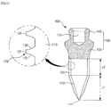
- FIG. 1 is an image of a palatal implant for an overdenture according to a first embodiment of the inventive concept
- FIG. 2 is a longitudinal section view of FIG. 1
- FIG. 3 is a view for explaining a placement position of the palatal implant for the overdenture of FIG. 1
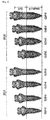
- FIG. 4 shows various alternative examples of the palatal implant for the overdenture of FIG. 1 .
- a palatal implant 100 for an overdenture in this embodiment is placed in a palatal to efficiently perform an implant surgical procedure under various abnormal conditions that a general implant surgical procedure is difficult.
- the palatal implant 100 for the overdenture includes an implant placement body 110 formed with a screw portion 120 on an outer surface thereof, and placed in a previously determined placement position P (refer to FIG. 3 ) of the palatal by work of the screw portion 120, and a head 150 connected to an upper portion of the implant placement body 110 and exposed to the outside at the placement position P.
- the head 150 includes a cuff 130 connected to the upper portion of the implant placement body 110, and an adjunct connecting portion 140 provided in the cuff 130 for connection with an adjunct (not shown).
- the implant placement body 110 indicates a region except the cuff 130 and the adjunct connecting portion 140 in FIG. 1 and FIG. 2 .
- the implant placement body 110 is implanted in a previously determined placement position P (refer to FIG. 3 ) of the palatal by work of the screw portion 120 formed on the outer surface thereof.
- the placement position P for the palatal implant 100 for the overdenture may correspond to a point distant from a center line (C/L) toward a premolar tooth by about 4 to 6 mm as shown in FIG. 3 , and preferably by 5 mm.
- the palatal implant 100 for the overdenture is vertically implanted. However, if the amount of bones in the palatal is small, the palatal implant 100 may be diagonally implanted at the placement position P.
- the implant placement body 110 is manufactured in the form of a sharp screw having no cutting edge.
- the implant placement body 110 is formed with a self-tapping sharpening portion 111 for self tapping at a lower end portion thereof so that it can be implanted in the placement position P (refer to FIG. 3 ) without drilling work.
- the self-tapping sharpening portion 111 is formed at the lower end portion of the implant placement body 110, so that the palatal implant 100 for the overdenture in this embodiment can be conveniently implanted without any separate drilling work, as long as the palatal implant 100 for the overdenture is rotated while the self-tapping sharpening portion 111 is put on the placement position P.
- implantation work is advantageously convenient.
- the screw portion 120 is formed so that the implant placement body 110 can be implanted into the placement position P.
- the screw portion 120 is continuously tapered from the self-tapping sharpening portion 111 forming the lower end portion of the implant placement body 110 to the cuff 130.
- the screw portion 120 is formed as a knife edge thread so that it can be sharply implanted without resisting bone density. That is, an edge forming the screw portion 120 is shaped like the blade of a knife.
- a virtual line connecting the outline of the screw portion 120 includes a curved line portion L1 formed from the self-tapping sharpening portion 111 to an approximately middle region of the implant placement body 110, and a straight line portion L2 formed from the end of the curved line portion L1 to the cuff 130.
- the straight line portion L2 serves to provide strong fixation power.
- the screw portion 120 is shaped like a square thread as enlarged in FIG. 2 .
- the screw portion 120 is not the complete square thread, but a modified form of combination between a square thread and a trapezoidal thread.
- the screw portion 120 includes a straight portion 121 forming a fore-end of the screw portion 120, and a curved portion 122 connected from the outer surface of the implant placement body 110 to the straight portion 121 of the screw portion 120.
- the curved portions 122 are symmetrically arranged at opposite sides with respect to the straight portion 121.
- Such features of the screw portion 120 provide the fixation power stronger than that of a typical implant.
- the implant placement body 110 including the screw portion 120 undergoes a surface treatment with calcium (Ca) ions for quick bone incorporation with the palatal.
- a surface treatment may advantageously cause optimum surface roughness and shorten a healing period.
- the length of the implant placement body 110 may be 4 to 6 mm, for example, 5 mm, but not limited thereto.
- the cuff 130 is connected to the upper portion of the implant placement body 110.
- the cuff 130 may be manufactured to have various lengths according to classifications so as to cope with various margins as shown in FIG. 4 .
- left four implant placement bodies 110 and right four implant placement bodies have diameters of 2.0 mm and 2.5 mm, respectively. Further, the implant placement bodies 110 having the same diameter may be different in length of the cuff 130.
- the cuffs 130 are manufactured to have various lengths, and selectively applied in accordance with states of a patient, thereby flexibly coping with various margins at the implant surgical procedure.
- the adjunct connecting portion 140 is a part protruding upward from the upper end of the cuff 130.
- the adjunct connecting portion 140 is a provided in the cuff 130 to connect with the adjunct (not shown) such as an implant cover, an abutment or various parts for fixing the denture.
- the adjunct connecting portion 140 has a protruding shape.
- the adjunct connecting portion 140 may be internally formed with a groove 141 into which the adjunct can be forcibly fitted. However, a top of the adjunct connecting portion 140 or the adjunct connecting portion 140 itself may be made of a magnet and thus magnetically coupled with the adjunct.
- An edge of the adjunct connecting portion 140 may be rounded so as to facilitate the connection with the adjunct. That is, even if the palatal implant 100 for the overdenture in this embodiment is obliquely implanted, the adjunct can be easily connected to the adjunct connecting portion 140.
- the cuff 130 and the adjunct connecting portion 140 may be formed as a single body to form the head 150.
- the head 150 may undergo surface treatment with zirconium nitride (ZrN) unlike the foregoing implant placement body 110.
- ZrN zirconium nitride
- the regions of the cuff 130 and the adjunct connecting portion 140 are more decreased in current density and more increased in corrosion resistance and hardness than those of before the surface treatment, and show gold color as a scratch or the like defects are removed.
- the placement position P (refer to FIG. 3 ) is first set up with regard to the palatal implant 100 for the overdenture.
- the placement position P for the palatal implant 100 for the overdenture may correspond to a point distant from the center line (C/L) toward the premolar tooth by about 4 to 6 mm as shown in FIG. 3 , and preferably by 5 mm.
- the position of the premolar tooth is not known, it may be determined based on an end of a palate.
- the palate refers to an upper portion of a mouth.
- the palatal implant 100 for the overdenture is vertically implanted. However, if the amount of bones in the palatal is small, the palatal implant 100 may be diagonally implanted at the placement position P.
- the palatal implant 100 for the overdenture is inserted in a designated driver and then the driver is rotated while the self-tapping sharpening portion 111 of the implant placement body 110 is put on the placement position P, thereby implanting the palatal implant 100 for the overdenture.
- the position is marked with paint or the like, and then a housing is mounted to the marked position.
- the palatal implant 100 for the overdenture is implanted in the palatal under various abnormal conditions that a surgical procedure of general implant placement for the overdenture is not easy, so that the implant surgical procedure can be readily and efficiently made.
- the palatal implant 100 for the overdenture is implanted in the palatal under various abnormal conditions: for example, there is no alveolar bone due to old age, the amount of bones around the implant is insufficient, an additional surgical procedure such as bone grafting for the implant placement is impossible, it is determined that a success rate of a general implant surgical procedure is low, there is a patient who cannot use the implant, etc. so that the implant surgical procedure can be readily and efficiently made.
- the implant can be placed in the palatal, i.e., the roof of the mouth so that dental treatment can be increased in variety. Further, the implant can be placed by only hands without any separate drilling, thereby facilitating the work.
- the palatal implant 100 can be provided at low cost as compared with the existing implant. Further, the palatal implant 100 is excellent in fixation power, and allows the surgical procedure to be performed soon after failure of implantation.
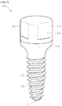
- FIG. 5 is a perspective view of a palatal implant for an overdenture according to an example which is not part of the present invention, in which adjunct are separated;
- FIG. 6 is a view showing that the adjunct and the implant of FIG. 5 are assembled; and
- FIG. 7 is a longitudinal section view of FIG. 6 .
- a palatal implant 200 for the overdenture in this embodiment includes an implant placement body 110 formed with a screw portion 120 on an outer surface thereof, and placed in a previously determined placement position P (refer to FIG. 3 ) of the palatal by work of the screw portion 120, a cuff 130 connected to an upper portion of the implant placement body 110, and an adjunct connecting portion 140 provided in the cuff 130 for connection with an adjunct 250 such as an implant cover.
- the structures and functions of the implant placement body 110, the screw portion 120 and the cuff 130 in this embodiment are the same as those of the foregoing embodiment, and thus descriptions of the implant placement body 110, the screw portion 120 and the cuff 130 will be replaced by the foregoing descriptions.
- the adjunct connecting portion 240 is provided in the form of a protrusion, in particular, in the form of a threaded protrusion.
- adjunct 250 is screw-coupled to the adjunct connecting portion 240 provided in the form of the threaded protrusion.
- a wrench engaging portion 251 is formed on an outer surface of the adjunct 250.
- the wrench engaging portion 251 forms a part with which a wrench drive is engaged.
- the adjunct 250 may be used as an abutment for coupling with a separate maintaining device (not shown).
- the palatal implant 200 for the overdenture is implanted in the palatal under various abnormal conditions that a surgical procedure of general implant placement for the overdenture is not easy, so that the implant surgical procedure can be efficiently made.
- FIG. 8 is a perspective view of a palatal implant for an overdenture according to an example which is not part of the present invention, in which the adjunct and the implant are separated; and FIG. 9 is a view showing that the adjunct and the implant of FIG. 8 are assembled.
- a palatal implant 300 for the overdenture in this embodiment includes an implant placement body 110 formed with a screw portion 120 on an outer surface thereof, and placed in a previously determined placement position P (refer to FIG. 3 ) of the palatal by work of the screw portion 120, a cuff 330 connected to an upper portion of the implant placement body 110, and an adjunct connecting portion 340 provided in the cuff 330 for connection with an adjunct 350 such as an implant cover.
- the adjunct connecting portion 340 is provided in the form of a groove.
- the adjunct 350 is screw-coupled to the adjunct connecting portion 340 provided in the form of the groove.
- the adjunct 350 is formed with a screw coupling portion 351 which is inserted in and screw-coupled to the adjunct connecting portion 340.
- the adjunct 350 may be coupled to the adjunct connecting portion 340 through a driver groove 353 formed on the top thereof.
- a wrench engaging portion 331 is provided for implanting the palatal implant 300 for the overdenture in this example.
- the palatal implant 300 for the overdenture is implanted in the palatal under various abnormal conditions that a surgical procedure of general implant placement for the overdenture is not easy, so that the implant surgical procedure can be efficiently made.
- the palatal implant for the overdenture is implanted in the palatal under various abnormal conditions that a surgical procedure of general implant placement for the overdenture is not easy, so that the implant surgical procedure can be efficiently made.
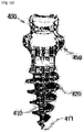
- FIG. 10 is an image of a palatal implant for an overdenture according to an embodiment of the present invention.
- a palatal implant 400 for the overdenture includes an implant placement body 410 formed with a screw portion 420 on an outer surface thereof, and placed in a previously determined placement position P (refer to FIG. 3 ) of the palatal by work of the screw portion 420, and a head 450 connected to an upper portion of the implant placement body 410 and exposed to the outside at the placement position P.
- the present inventive concept is applicable to the field of a dental care.
Landscapes
- Health & Medical Sciences (AREA)
- Animal Behavior & Ethology (AREA)
- Dentistry (AREA)
- Epidemiology (AREA)
- Life Sciences & Earth Sciences (AREA)
- Oral & Maxillofacial Surgery (AREA)
- General Health & Medical Sciences (AREA)
- Public Health (AREA)
- Veterinary Medicine (AREA)
- Orthopedic Medicine & Surgery (AREA)
- Engineering & Computer Science (AREA)
- Ceramic Engineering (AREA)
- Dental Prosthetics (AREA)
- Prostheses (AREA)
Claims (1)
- Implant palatin (100) pour une prothèse amovible complète supra-implantaire, comprenant :un corps de pose d'implant (110) qui est implantable à un emplacement de pose déterminé précédemment d'un palais pour la prothèse amovible complète supra-implantaire au moyen d'une partie filetée (120) formée sur une surface extérieure de celui-ci ; etune tête (150) qui comprend une douille (130) raccordée à une partie supérieure du corps de pose d'implant (110) et une partie de raccordement d'élément complémentaire (140) prévue dans la douille (130) à des fins d'accouplement avec un élément complémentaire, et qui peut être exposée à une région extérieure au niveau de l'emplacement de pose, la partie de raccordement d'élément complémentaire (140) étant réalisée sous la forme d'une protubérance orientée vers le haut à partir d'une extrémité supérieure de la douille (130), la douille (130) et la partie de raccordement d'élément complémentaire (140) étant réalisées sous la forme d'un corps d'un seul tenant,caractérisé en ce qu'un bord de la partie de raccordement d'élément complémentaire (140) est arrondi, et la partie de raccordement d'élément complémentaire (140) comprend un aimant à des fins d'accouplement magnétique avec l'élément complémentaire.
Applications Claiming Priority (2)
| Application Number | Priority Date | Filing Date | Title |
|---|---|---|---|
| KR1020120112158A KR101462042B1 (ko) | 2012-10-10 | 2012-10-10 | 오버덴쳐용 팔라탈 임플란트 |
| PCT/KR2013/007304 WO2014058149A1 (fr) | 2012-10-10 | 2013-08-14 | Implant palatin pour prothèse dentaire |
Publications (3)
| Publication Number | Publication Date |
|---|---|
| EP2907473A1 EP2907473A1 (fr) | 2015-08-19 |
| EP2907473A4 EP2907473A4 (fr) | 2015-12-16 |
| EP2907473B1 true EP2907473B1 (fr) | 2017-06-21 |
Family
ID=50477583
Family Applications (1)
| Application Number | Title | Priority Date | Filing Date |
|---|---|---|---|
| EP13844937.6A Active EP2907473B1 (fr) | 2012-10-10 | 2013-08-14 | Implant palatin pour prothèse dentaire |
Country Status (6)
| Country | Link |
|---|---|
| US (1) | US20150216631A1 (fr) |
| EP (1) | EP2907473B1 (fr) |
| KR (1) | KR101462042B1 (fr) |
| ES (1) | ES2637140T3 (fr) |
| TW (1) | TWI598078B (fr) |
| WO (1) | WO2014058149A1 (fr) |
Families Citing this family (5)
| Publication number | Priority date | Publication date | Assignee | Title |
|---|---|---|---|---|
| TWI571806B (zh) * | 2014-05-27 | 2017-02-21 | Metal Ind Res And Dev Centre | Tooth body image joining method |
| PT108965A (pt) * | 2015-11-18 | 2017-05-18 | Miguel Dos Santos Roseiro Pedro | Pilar de conexão autodirecionado com quatro retenções [pcad-qr], chave manual e chave de torque e soluções de fixação de nível intermédio |
| IL243523B (en) * | 2016-01-10 | 2022-08-01 | Cortex Dental Implants Ind Ltd | Drill-less dental implant |
| US11786346B2 (en) | 2019-01-11 | 2023-10-17 | Trion Concepts, Inc. | Bone-mounted dental arch veneers and methods for fabricating and utilizing the same |
| WO2023154979A1 (fr) * | 2022-02-18 | 2023-08-24 | Maxoniq IP Pty Ltd | Prothèse dentaire à retenue magnétique |
Family Cites Families (17)
| Publication number | Priority date | Publication date | Assignee | Title |
|---|---|---|---|---|
| US3514858A (en) * | 1969-04-14 | 1970-06-02 | Ralph H Silverman | Denture securing apparatus |
| DE3237174C2 (de) * | 1981-11-14 | 1984-04-12 | Feldmühle AG, 4000 Düsseldorf | Befestigungssystem für eine schleimhautgetragene Prothese |
| WO2002028304A2 (fr) * | 2000-10-04 | 2002-04-11 | Bernard Weissman | Composants modulaires adaptables pour l'assemblage de protheses et ponts dentaires |
| CN100515504C (zh) * | 2001-10-12 | 2009-07-22 | 美国英佛曼公司 | 涂层,涂布体及其制造方法 |
| JP2004113509A (ja) * | 2002-09-26 | 2004-04-15 | Aichi Steel Works Ltd | 義歯アタッチメント用キーパ |
| US20070077535A1 (en) * | 2003-09-16 | 2007-04-05 | Manfred Wichmann | Method for the production of a set of dentures for an untoothed or partially toothed jaw |
| SE0400546D0 (sv) * | 2004-03-05 | 2004-03-05 | Dan Lundgren | Rörformigt benförankringselement |
| EP1791491A1 (fr) * | 2004-09-14 | 2007-06-06 | Oratio B.V. | Procede de fabrication et d'installation d'un implant dentaire ceramique avec une partie d'appui d'implant esthetique |
| JP2006271767A (ja) * | 2005-03-30 | 2006-10-12 | Gc Corp | 歯科インプラント用磁性アタッチメント |
| KR20080110391A (ko) * | 2007-06-15 | 2008-12-18 | 조선대학교산학협력단 | 임플란트 |
| KR100807150B1 (ko) * | 2007-08-27 | 2008-02-27 | 주식회사 메가젠임플란트 | 오버덴쳐 시술용 임플란트 |
| US9314318B2 (en) * | 2008-08-26 | 2016-04-19 | Zest Ip Holdings, Llc | Dental anchor apparatus and method |
| IT1392605B1 (it) * | 2008-12-31 | 2012-03-09 | Hdc S R L | Dispositivo di fissaggio per apparecchi ortodontici |
| KR100931210B1 (ko) * | 2009-07-22 | 2009-12-10 | 윤우성 | 치과 교정용 나사 조립체 |
| KR101131115B1 (ko) * | 2010-03-31 | 2012-04-03 | 서정운 | 충격흡수가 용이한 임플란트용 픽스쳐 |
| KR20120008672A (ko) * | 2010-07-19 | 2012-02-01 | 공용표 | 인공치근 및 이를 이용한 의치구조 |
| JP5100918B2 (ja) * | 2011-03-28 | 2012-12-19 | 株式会社T・U・M | 義歯システム、入れ歯の作成方法および補修方法 |
-
2012
- 2012-10-10 KR KR1020120112158A patent/KR101462042B1/ko active Active
-
2013
- 2013-08-14 EP EP13844937.6A patent/EP2907473B1/fr active Active
- 2013-08-14 WO PCT/KR2013/007304 patent/WO2014058149A1/fr not_active Ceased
- 2013-08-14 ES ES13844937.6T patent/ES2637140T3/es active Active
- 2013-08-14 US US14/429,730 patent/US20150216631A1/en not_active Abandoned
- 2013-08-19 TW TW102129640A patent/TWI598078B/zh active
Non-Patent Citations (1)
| Title |
|---|
| None * |
Also Published As
| Publication number | Publication date |
|---|---|
| US20150216631A1 (en) | 2015-08-06 |
| EP2907473A1 (fr) | 2015-08-19 |
| WO2014058149A1 (fr) | 2014-04-17 |
| TWI598078B (zh) | 2017-09-11 |
| EP2907473A4 (fr) | 2015-12-16 |
| KR101462042B1 (ko) | 2014-11-18 |
| ES2637140T3 (es) | 2017-10-11 |
| KR20140046123A (ko) | 2014-04-18 |
| TW201414458A (zh) | 2014-04-16 |
Similar Documents
| Publication | Publication Date | Title |
|---|---|---|
| US8540512B2 (en) | Dental implant system | |
| KR101108280B1 (ko) | 임플란트 | |
| KR20030089602A (ko) | 치과용 임플란트의 구조 | |
| KR101140620B1 (ko) | 골이식 임플란트 시술용 임시 체결 부재 | |
| JP4694453B2 (ja) | 治癒支台柱 | |
| EP2835110A1 (fr) | Accessoire de fixation de prothèse dentaire présentant un angle et une position librement ajustables | |
| US20180280121A1 (en) | Dental implant systems and methods of implantation | |
| US20150216631A1 (en) | Palatal implant for overdenture | |
| JP2017196363A (ja) | アバットメント分離用ツール | |
| KR20180011103A (ko) | 골내 단일 치아 임플란트를 위한 삽입 키트 | |
| KR101446072B1 (ko) | 인상채득이 가능한 힐링 어버트먼트 | |
| KR101056357B1 (ko) | 임플란트 시술용 임프레션 코핑 | |
| KR101388185B1 (ko) | 인상채득이 가능한 힐링 어버트먼트 | |
| KR101473835B1 (ko) | 힐링 어버트먼트에 체결이 가능한 보호 캡 | |
| KR20080103318A (ko) | 응급 임플란트용 고정체 | |
| KR101571759B1 (ko) | 치과용 임플란트 장치 | |
| KR101067484B1 (ko) | 임플란트 시술용 임프레션 코핑 | |
| KR20150115057A (ko) | 임플란트용 인공치근 | |
| KR101879550B1 (ko) | 구조개선을 통한 조립의 용이성을 향상시킨 임플란트의 어버트먼트 | |
| US20080076092A1 (en) | Abutment coping for dental implant fixture | |
| KR200392276Y1 (ko) | 치과용 임플란트 | |
| KR20050078806A (ko) | 임시 임플란트 | |
| KR200286847Y1 (ko) | 치과용 임플란트의 구조 | |
| KR200428106Y1 (ko) | 치유 지대주 및 그를 구비한 임플란트 | |
| JP4108217B2 (ja) | 歯科インプラント埋入用治具 |
Legal Events
| Date | Code | Title | Description |
|---|---|---|---|
| PUAI | Public reference made under article 153(3) epc to a published international application that has entered the european phase |
Free format text: ORIGINAL CODE: 0009012 |
|
| 17P | Request for examination filed |
Effective date: 20150319 |
|
| AK | Designated contracting states |
Kind code of ref document: A1 Designated state(s): AL AT BE BG CH CY CZ DE DK EE ES FI FR GB GR HR HU IE IS IT LI LT LU LV MC MK MT NL NO PL PT RO RS SE SI SK SM TR |
|
| AX | Request for extension of the european patent |
Extension state: BA ME |
|
| RIC1 | Information provided on ipc code assigned before grant |
Ipc: A61C 8/00 20060101AFI20150827BHEP Ipc: A61C 13/263 20060101ALI20150827BHEP Ipc: A61C 13/235 20060101ALI20150827BHEP Ipc: A61C 13/265 20060101ALI20150827BHEP |
|
| RA4 | Supplementary search report drawn up and despatched (corrected) |
Effective date: 20151112 |
|
| RIC1 | Information provided on ipc code assigned before grant |
Ipc: A61C 8/00 20060101AFI20151106BHEP Ipc: A61C 13/265 20060101ALI20151106BHEP Ipc: A61C 13/263 20060101ALI20151106BHEP Ipc: A61C 13/235 20060101ALI20151106BHEP |
|
| DAX | Request for extension of the european patent (deleted) | ||
| 17Q | First examination report despatched |
Effective date: 20151222 |
|
| GRAP | Despatch of communication of intention to grant a patent |
Free format text: ORIGINAL CODE: EPIDOSNIGR1 |
|
| INTG | Intention to grant announced |
Effective date: 20170127 |
|
| GRAS | Grant fee paid |
Free format text: ORIGINAL CODE: EPIDOSNIGR3 |
|
| GRAA | (expected) grant |
Free format text: ORIGINAL CODE: 0009210 |
|
| AK | Designated contracting states |
Kind code of ref document: B1 Designated state(s): AL AT BE BG CH CY CZ DE DK EE ES FI FR GB GR HR HU IE IS IT LI LT LU LV MC MK MT NL NO PL PT RO RS SE SI SK SM TR |
|
| REG | Reference to a national code |
Ref country code: GB Ref legal event code: FG4D |
|
| REG | Reference to a national code |
Ref country code: CH Ref legal event code: EP |
|
| REG | Reference to a national code |
Ref country code: IE Ref legal event code: FG4D |
|
| REG | Reference to a national code |
Ref country code: AT Ref legal event code: REF Ref document number: 902246 Country of ref document: AT Kind code of ref document: T Effective date: 20170715 |
|
| REG | Reference to a national code |
Ref country code: DE Ref legal event code: R096 Ref document number: 602013022687 Country of ref document: DE |
|
| REG | Reference to a national code |
Ref country code: CH Ref legal event code: NV Representative=s name: FELBER UND PARTNER AG, CH |
|
| REG | Reference to a national code |
Ref country code: FR Ref legal event code: PLFP Year of fee payment: 5 |
|
| REG | Reference to a national code |
Ref country code: SE Ref legal event code: TRGR |
|
| REG | Reference to a national code |
Ref country code: ES Ref legal event code: FG2A Ref document number: 2637140 Country of ref document: ES Kind code of ref document: T3 Effective date: 20171011 |
|
| REG | Reference to a national code |
Ref country code: NL Ref legal event code: MP Effective date: 20170621 |
|
| PG25 | Lapsed in a contracting state [announced via postgrant information from national office to epo] |
Ref country code: NO Free format text: LAPSE BECAUSE OF FAILURE TO SUBMIT A TRANSLATION OF THE DESCRIPTION OR TO PAY THE FEE WITHIN THE PRESCRIBED TIME-LIMIT Effective date: 20170921 Ref country code: FI Free format text: LAPSE BECAUSE OF FAILURE TO SUBMIT A TRANSLATION OF THE DESCRIPTION OR TO PAY THE FEE WITHIN THE PRESCRIBED TIME-LIMIT Effective date: 20170621 Ref country code: GR Free format text: LAPSE BECAUSE OF FAILURE TO SUBMIT A TRANSLATION OF THE DESCRIPTION OR TO PAY THE FEE WITHIN THE PRESCRIBED TIME-LIMIT Effective date: 20170922 Ref country code: HR Free format text: LAPSE BECAUSE OF FAILURE TO SUBMIT A TRANSLATION OF THE DESCRIPTION OR TO PAY THE FEE WITHIN THE PRESCRIBED TIME-LIMIT Effective date: 20170621 Ref country code: LT Free format text: LAPSE BECAUSE OF FAILURE TO SUBMIT A TRANSLATION OF THE DESCRIPTION OR TO PAY THE FEE WITHIN THE PRESCRIBED TIME-LIMIT Effective date: 20170621 |
|
| REG | Reference to a national code |
Ref country code: LT Ref legal event code: MG4D |
|
| REG | Reference to a national code |
Ref country code: AT Ref legal event code: MK05 Ref document number: 902246 Country of ref document: AT Kind code of ref document: T Effective date: 20170621 |
|
| PG25 | Lapsed in a contracting state [announced via postgrant information from national office to epo] |
Ref country code: LV Free format text: LAPSE BECAUSE OF FAILURE TO SUBMIT A TRANSLATION OF THE DESCRIPTION OR TO PAY THE FEE WITHIN THE PRESCRIBED TIME-LIMIT Effective date: 20170621 Ref country code: BG Free format text: LAPSE BECAUSE OF FAILURE TO SUBMIT A TRANSLATION OF THE DESCRIPTION OR TO PAY THE FEE WITHIN THE PRESCRIBED TIME-LIMIT Effective date: 20170921 Ref country code: RS Free format text: LAPSE BECAUSE OF FAILURE TO SUBMIT A TRANSLATION OF THE DESCRIPTION OR TO PAY THE FEE WITHIN THE PRESCRIBED TIME-LIMIT Effective date: 20170621 Ref country code: NL Free format text: LAPSE BECAUSE OF FAILURE TO SUBMIT A TRANSLATION OF THE DESCRIPTION OR TO PAY THE FEE WITHIN THE PRESCRIBED TIME-LIMIT Effective date: 20170621 |
|
| PG25 | Lapsed in a contracting state [announced via postgrant information from national office to epo] |
Ref country code: CZ Free format text: LAPSE BECAUSE OF FAILURE TO SUBMIT A TRANSLATION OF THE DESCRIPTION OR TO PAY THE FEE WITHIN THE PRESCRIBED TIME-LIMIT Effective date: 20170621 Ref country code: RO Free format text: LAPSE BECAUSE OF FAILURE TO SUBMIT A TRANSLATION OF THE DESCRIPTION OR TO PAY THE FEE WITHIN THE PRESCRIBED TIME-LIMIT Effective date: 20170621 Ref country code: EE Free format text: LAPSE BECAUSE OF FAILURE TO SUBMIT A TRANSLATION OF THE DESCRIPTION OR TO PAY THE FEE WITHIN THE PRESCRIBED TIME-LIMIT Effective date: 20170621 Ref country code: AT Free format text: LAPSE BECAUSE OF FAILURE TO SUBMIT A TRANSLATION OF THE DESCRIPTION OR TO PAY THE FEE WITHIN THE PRESCRIBED TIME-LIMIT Effective date: 20170621 Ref country code: SK Free format text: LAPSE BECAUSE OF FAILURE TO SUBMIT A TRANSLATION OF THE DESCRIPTION OR TO PAY THE FEE WITHIN THE PRESCRIBED TIME-LIMIT Effective date: 20170621 |
|
| PG25 | Lapsed in a contracting state [announced via postgrant information from national office to epo] |
Ref country code: SM Free format text: LAPSE BECAUSE OF FAILURE TO SUBMIT A TRANSLATION OF THE DESCRIPTION OR TO PAY THE FEE WITHIN THE PRESCRIBED TIME-LIMIT Effective date: 20170621 Ref country code: PL Free format text: LAPSE BECAUSE OF FAILURE TO SUBMIT A TRANSLATION OF THE DESCRIPTION OR TO PAY THE FEE WITHIN THE PRESCRIBED TIME-LIMIT Effective date: 20170621 Ref country code: IS Free format text: LAPSE BECAUSE OF FAILURE TO SUBMIT A TRANSLATION OF THE DESCRIPTION OR TO PAY THE FEE WITHIN THE PRESCRIBED TIME-LIMIT Effective date: 20171021 |
|
| REG | Reference to a national code |
Ref country code: DE Ref legal event code: R097 Ref document number: 602013022687 Country of ref document: DE |
|
| PG25 | Lapsed in a contracting state [announced via postgrant information from national office to epo] |
Ref country code: MC Free format text: LAPSE BECAUSE OF FAILURE TO SUBMIT A TRANSLATION OF THE DESCRIPTION OR TO PAY THE FEE WITHIN THE PRESCRIBED TIME-LIMIT Effective date: 20170621 |
|
| PLBE | No opposition filed within time limit |
Free format text: ORIGINAL CODE: 0009261 |
|
| STAA | Information on the status of an ep patent application or granted ep patent |
Free format text: STATUS: NO OPPOSITION FILED WITHIN TIME LIMIT |
|
| PG25 | Lapsed in a contracting state [announced via postgrant information from national office to epo] |
Ref country code: DK Free format text: LAPSE BECAUSE OF FAILURE TO SUBMIT A TRANSLATION OF THE DESCRIPTION OR TO PAY THE FEE WITHIN THE PRESCRIBED TIME-LIMIT Effective date: 20170621 |
|
| 26N | No opposition filed |
Effective date: 20180322 |
|
| REG | Reference to a national code |
Ref country code: IE Ref legal event code: MM4A |
|
| REG | Reference to a national code |
Ref country code: BE Ref legal event code: MM Effective date: 20170831 |
|
| PG25 | Lapsed in a contracting state [announced via postgrant information from national office to epo] |
Ref country code: LU Free format text: LAPSE BECAUSE OF NON-PAYMENT OF DUE FEES Effective date: 20170814 |
|
| PG25 | Lapsed in a contracting state [announced via postgrant information from national office to epo] |
Ref country code: IE Free format text: LAPSE BECAUSE OF NON-PAYMENT OF DUE FEES Effective date: 20170814 |
|
| REG | Reference to a national code |
Ref country code: FR Ref legal event code: PLFP Year of fee payment: 6 |
|
| PG25 | Lapsed in a contracting state [announced via postgrant information from national office to epo] |
Ref country code: BE Free format text: LAPSE BECAUSE OF NON-PAYMENT OF DUE FEES Effective date: 20170831 Ref country code: SI Free format text: LAPSE BECAUSE OF FAILURE TO SUBMIT A TRANSLATION OF THE DESCRIPTION OR TO PAY THE FEE WITHIN THE PRESCRIBED TIME-LIMIT Effective date: 20170621 |
|
| PG25 | Lapsed in a contracting state [announced via postgrant information from national office to epo] |
Ref country code: MT Free format text: LAPSE BECAUSE OF NON-PAYMENT OF DUE FEES Effective date: 20170814 |
|
| PG25 | Lapsed in a contracting state [announced via postgrant information from national office to epo] |
Ref country code: HU Free format text: LAPSE BECAUSE OF FAILURE TO SUBMIT A TRANSLATION OF THE DESCRIPTION OR TO PAY THE FEE WITHIN THE PRESCRIBED TIME-LIMIT; INVALID AB INITIO Effective date: 20130814 |
|
| PG25 | Lapsed in a contracting state [announced via postgrant information from national office to epo] |
Ref country code: CY Free format text: LAPSE BECAUSE OF FAILURE TO SUBMIT A TRANSLATION OF THE DESCRIPTION OR TO PAY THE FEE WITHIN THE PRESCRIBED TIME-LIMIT Effective date: 20170621 |
|
| PG25 | Lapsed in a contracting state [announced via postgrant information from national office to epo] |
Ref country code: MK Free format text: LAPSE BECAUSE OF FAILURE TO SUBMIT A TRANSLATION OF THE DESCRIPTION OR TO PAY THE FEE WITHIN THE PRESCRIBED TIME-LIMIT Effective date: 20170621 |
|
| PG25 | Lapsed in a contracting state [announced via postgrant information from national office to epo] |
Ref country code: TR Free format text: LAPSE BECAUSE OF FAILURE TO SUBMIT A TRANSLATION OF THE DESCRIPTION OR TO PAY THE FEE WITHIN THE PRESCRIBED TIME-LIMIT Effective date: 20170621 |
|
| PG25 | Lapsed in a contracting state [announced via postgrant information from national office to epo] |
Ref country code: PT Free format text: LAPSE BECAUSE OF FAILURE TO SUBMIT A TRANSLATION OF THE DESCRIPTION OR TO PAY THE FEE WITHIN THE PRESCRIBED TIME-LIMIT Effective date: 20170621 |
|
| PG25 | Lapsed in a contracting state [announced via postgrant information from national office to epo] |
Ref country code: AL Free format text: LAPSE BECAUSE OF FAILURE TO SUBMIT A TRANSLATION OF THE DESCRIPTION OR TO PAY THE FEE WITHIN THE PRESCRIBED TIME-LIMIT Effective date: 20170621 |
|
| PGFP | Annual fee paid to national office [announced via postgrant information from national office to epo] |
Ref country code: ES Payment date: 20250910 Year of fee payment: 13 |
|
| PGFP | Annual fee paid to national office [announced via postgrant information from national office to epo] |
Ref country code: DE Payment date: 20250819 Year of fee payment: 13 |
|
| PGFP | Annual fee paid to national office [announced via postgrant information from national office to epo] |
Ref country code: IT Payment date: 20250821 Year of fee payment: 13 |
|
| PGFP | Annual fee paid to national office [announced via postgrant information from national office to epo] |
Ref country code: GB Payment date: 20250819 Year of fee payment: 13 |
|
| PGFP | Annual fee paid to national office [announced via postgrant information from national office to epo] |
Ref country code: FR Payment date: 20250818 Year of fee payment: 13 |
|
| PGFP | Annual fee paid to national office [announced via postgrant information from national office to epo] |
Ref country code: CH Payment date: 20250901 Year of fee payment: 13 Ref country code: SE Payment date: 20250819 Year of fee payment: 13 |