EP2907577A1 - Vorrichtung für Biogasanlagen zum Zerkleinern und Zermahlen von Flüssig-Feststoffgemischen - Google Patents
Vorrichtung für Biogasanlagen zum Zerkleinern und Zermahlen von Flüssig-Feststoffgemischen Download PDFInfo
- Publication number
- EP2907577A1 EP2907577A1 EP15154986.2A EP15154986A EP2907577A1 EP 2907577 A1 EP2907577 A1 EP 2907577A1 EP 15154986 A EP15154986 A EP 15154986A EP 2907577 A1 EP2907577 A1 EP 2907577A1
- Authority
- EP
- European Patent Office
- Prior art keywords
- drum
- wall
- balls
- liquid
- comminuted
- Prior art date
- Legal status (The legal status is an assumption and is not a legal conclusion. Google has not performed a legal analysis and makes no representation as to the accuracy of the status listed.)
- Granted
Links
- 239000008247 solid mixture Substances 0.000 title claims abstract description 7
- 238000003801 milling Methods 0.000 title description 3
- 239000000463 material Substances 0.000 claims abstract description 14
- 238000000227 grinding Methods 0.000 claims abstract description 6
- 239000013013 elastic material Substances 0.000 claims description 3
- 238000000855 fermentation Methods 0.000 description 4
- 230000004151 fermentation Effects 0.000 description 4
- 239000007787 solid Substances 0.000 description 4
- 239000000835 fiber Substances 0.000 description 3
- 239000007788 liquid Substances 0.000 description 2
- 238000000034 method Methods 0.000 description 2
- 230000003534 oscillatory effect Effects 0.000 description 2
- 230000035939 shock Effects 0.000 description 2
- 239000000758 substrate Substances 0.000 description 2
- 239000002657 fibrous material Substances 0.000 description 1
- 239000011521 glass Substances 0.000 description 1
- 230000003116 impacting effect Effects 0.000 description 1
- 238000009413 insulation Methods 0.000 description 1
- 238000004519 manufacturing process Methods 0.000 description 1
- 239000000203 mixture Substances 0.000 description 1
- 239000004033 plastic Substances 0.000 description 1
- 229920003023 plastic Polymers 0.000 description 1
- 239000000843 powder Substances 0.000 description 1
- 239000002994 raw material Substances 0.000 description 1
- 238000003756 stirring Methods 0.000 description 1
- 239000004575 stone Substances 0.000 description 1
Images
Classifications
-
- B—PERFORMING OPERATIONS; TRANSPORTING
- B02—CRUSHING, PULVERISING, OR DISINTEGRATING; PREPARATORY TREATMENT OF GRAIN FOR MILLING
- B02C—CRUSHING, PULVERISING, OR DISINTEGRATING IN GENERAL; MILLING GRAIN
- B02C17/00—Disintegrating by tumbling mills, i.e. mills having a container charged with the material to be disintegrated with or without special disintegrating members such as pebbles or balls
- B02C17/10—Disintegrating by tumbling mills, i.e. mills having a container charged with the material to be disintegrated with or without special disintegrating members such as pebbles or balls with one or a few disintegrating members arranged in the container
-
- B—PERFORMING OPERATIONS; TRANSPORTING
- B02—CRUSHING, PULVERISING, OR DISINTEGRATING; PREPARATORY TREATMENT OF GRAIN FOR MILLING
- B02C—CRUSHING, PULVERISING, OR DISINTEGRATING IN GENERAL; MILLING GRAIN
- B02C17/00—Disintegrating by tumbling mills, i.e. mills having a container charged with the material to be disintegrated with or without special disintegrating members such as pebbles or balls
- B02C17/04—Disintegrating by tumbling mills, i.e. mills having a container charged with the material to be disintegrated with or without special disintegrating members such as pebbles or balls with unperforated container
-
- B—PERFORMING OPERATIONS; TRANSPORTING
- B02—CRUSHING, PULVERISING, OR DISINTEGRATING; PREPARATORY TREATMENT OF GRAIN FOR MILLING
- B02C—CRUSHING, PULVERISING, OR DISINTEGRATING IN GENERAL; MILLING GRAIN
- B02C17/00—Disintegrating by tumbling mills, i.e. mills having a container charged with the material to be disintegrated with or without special disintegrating members such as pebbles or balls
- B02C17/18—Details
- B02C17/183—Feeding or discharging devices
- B02C17/1835—Discharging devices combined with sorting or separating of material
- B02C17/1855—Discharging devices combined with sorting or separating of material with separator defining termination of crushing zone, e.g. screen denying egress of oversize material
Definitions
- the invention relates to a device for use in biogas plants for crushing and grinding of liquid-solid mixtures.
- ball mills In various economic sectors, eg B. in powder production, ball mills are used, which are charged in batches.
- the ball mill has a drum with a flap that must be opened to fill the raw material and to be able to remove the ground product after crushing again.
- Such ball mills are for example made DE 233 164 known in several versions.
- the crushing is done by a vertically movable rammer, which comminutes the material within a conical container.
- the grinding bodies designed as balls are located in a vertically arranged cylinder with a sieve bottom, wherein the cylinder is set in vibration.
- the cylindrical drum is arranged horizontally and is moved about its horizontal axis via a flywheel in reciprocating shaking movements. The material to be ground is filled at one end over a hopper and leaves the drum through an axial opening on the opposite end.
- liquid-solid mixtures such as liquid fermentation substrates with high fiber content must be crushed.
- the invention has for its object to provide a suitable for use in biogas plants device for crushing and grinding of liquid-solid mixtures available, in which the material to be ground continuously, z. B. by means of a pump, is passed during the milling process in a closed system.
- the ball mill has advantageously a rotatably driven about a horizontal axis driven, filled with balls drum which is closed at one end by a cover and at the other end by a bottom, wherein on both end faces a rotary feedthrough for the continuous feed with the comminuting material or intended for the continuous delivery of the comminuted material.
- the balls ensure that the fiber content of the fermentation substrate and moreover contained solids such as stones, glass or plastics are reliably crushed, so that no damage is caused in downstream pumps.
- the residence times can be reduced in the downstream fermentation tanks and the biogas yield can be significantly increased. Also as a result, floating layers in fermentation residue stores are significantly reduced and the power consumption for necessary stirring energies is considerably reduced.
- the two rotary feedthroughs on the front sides of the drum allow a continuous, automatic operation, since a loading flap for the drum is eliminated.
- the feed with the liquid-solid mixture during the ongoing rotation of the drum done a pump.
- the cylindrical inner wall of the drum is concentric in a cylindrical outer wall levitating and mechanically decoupled, since it is radially movable as an independent inner drum in the driven outer drum.
- an insulating layer of elastic material can be used between the inner wall and the outer wall. In this way, not only the noise during operation, which is caused by the impacting balls, significantly reduced, but also the shock and vibration stress of the entire drum, which significantly increases their life. If the inner drum becomes worn, it can be easily removed and replaced with a new inner wall.
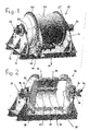
- the ball mill 10 intended for use in biogas plants according to the invention is mounted on a base plate 12, from which two parallel vertical walls 14 extend upwards.
- Each vertical wall 14 has in the upper area Cylindrical roller bearing 16 for rotatably supporting a pipe socket 18 which is fixedly connected to the bottom 20 and the cover 22 of a cylindrical drum 24.
- the two pipe sockets 18 on the two end faces of the drum 24 serve as rotary feedthroughs 26, which open into the interior of the drum 24 and fed via which the material to be comminuted on the right in the figures end face of the drum 24 and continuously discharged again on the opposite end face becomes.
- a screen plate 28th On the left side in the figures of the drum 24 is located between the interior of the drum 24 and the rotary feedthrough 26 for the delivery of the shredded material, a screen plate 28th
- the interior of the drum 24 is filled with balls formed as balls 30 which are detected during the rotation of the drum 24 about its longitudinal axis of Mitêtchann 32 which extend in the longitudinal direction of the drum 24 and are secured to the inner wall 34.
- the cylindrical inner wall 34 of the drum 24 is mounted concentrically floating in a cylindrical outer wall 36, wherein between the inner wall 34 and outer wall 36, an insulating layer 38 is inserted from elastic material, which may be formed as a mat.
- elastic material which may be formed as a mat.
- FIG. 1 shows, on the outer wall 36 of the drum 24, a sprocket 40 is mounted, with which a drive chain 42 is engaged.
- the drive chain 42 passes over a pinion 44, which is rotated by a drive motor 46 in rotation, which is supported next to the drum 24 on the bottom plate 12.
- the speed of the drive motor 46 can be adjusted in order to adapt the grinding process to the respective regrind and its composition of liquid and solids can.
Landscapes
- Engineering & Computer Science (AREA)
- Food Science & Technology (AREA)
- Crushing And Grinding (AREA)
Abstract
Description
- Die Erfindung betrifft eine Vorrichtung für die Verwendung in Biogasanlagen zum Zerkleinern und Zermahlen von Flüssig- Feststoffgemischen.
- In verschiedenen Wirtschaftszweigen, z. B. bei der Puderherstellung, werden Kugelmühlen eingesetzt, die chargenweise beschickt werden. Hierzu hat die Kugelmühle eine Trommel mit einer Klappe, die geöffnet werden muss, um das Rohmaterial einzufüllen und nach der Zerkleinerung das gemahlene Produkt wieder entnehmen zu können.
- Derartige Kugelmühlen sind beispielsweise aus
DE 233 164 in mehreren Ausführungen bekannt. Bei einer ersten Bauart erfolgt die Zerkleinerung durch einen vertikal beweglichen Stampfer, der das Gut innerhalb eines konischen Behälters zerkleinert. In einem zweiten Beispiel befinden sich die als Kugeln ausgebildeten Mahlkörper in einem stehend angeordneten Zylinder mit einem Siebboden, wobei der Zylinder in Schwingungen versetzt wird. In einem weiteren Ausführungsbeispiel ist die zylindrische Trommel liegend angeordnet und wird um ihre horizontale Achse über einen Schwungkörper in hin- und hergehende Schüttelbewegungen versetzt. Das Mahlgut wird an einer Stirnseite über einen Trichter eingefüllt und verlässt die Trommel durch eine Axialöffnung auf der gegenüberliegenden Stirnseite. - Für den Betrieb von Biogasanlagen müssen Flüssig-Feststoffgemische wie etwa flüssige Gärsubstrate mit hohem Faseranteil zerkleinert werden.
- Der Erfindung liegt die Aufgabe zugrunde, eine für den Einsatz in Biogasanlagen geeignete Vorrichtung zum Zerkleinern und Zermahlen von Flüssig-Feststoffgemischen zur Verfügung zu stellen, bei der das zu vermahlende Gut kontinuierlich, z. B. mittels einer Pumpe, während des Mahlprozesses in einem geschlossenem System durchgeleitet wird.
- Zur Lösung dieser Aufgabe dient die Verwendung einer in Biogasanlagen bisher nicht eingesetzten Kugelmühle gemäß Anspruch 1, die während des Prozesses nicht angehalten und in einem gesonderten Arbeitsgang befüllt oder entleert werden muss. Damit ist auch ein Geruchs- und Gasproblem wie in einem offenen System, beispielsweise mit Trichterzuführung, ausgeschlossen.
- Die Kugelmühle hat in vorteilhafter Weise eine um eine horizontale Achse drehbar angetriebene, mit Kugeln befüllte Trommel, die an einer Stirnseite durch einen Deckel und an der anderen Stirnseite durch einen Boden geschlossen ist, wobei an beiden Stirnseiten eine Drehdurchführung für die kontinuierliche Beschickung mit dem zu zerkleinernden Gut bzw. für die kontinuierliche Abgabe des zerkleinerten Gutes vorgesehen ist. Während der Rotation der Trommel sorgen die Kugeln dafür, dass die Faseranteile des Gärsubstrates und darüber hinaus darin enthaltene Feststoffe wie Steine, Glas oder Kunststoffe zuverlässig zerrieben werden, damit in nachgeschalteten Pumpen keine Beschädigungen verursacht werden.
- In Weiterbildung der Erfindung sind an der Innenwand der Trommel in deren Längsrichtung verlaufende Mitnehmerleisten für die Kugeln angebracht. Diese sorgen dafür, dass bei der Drehbewegung der Trommel ausschließlich um ihre Längsachse die Kugeln ständig auf einem Teil des Umfangs der Innenwand mitgenommen werden und vor Erreichen des Scheitels der Trommel auf das zu zerkleinernde Gut herabfallen, wo sie durch ihr Gewicht sowohl Fasermaterial als auch Feststoffe zuverlässig zerreiben und zerkleinern. Mit einer derartigen Ausgestaltung der Trommel ist es im Gegensatz zum Stand der Technik nach
DE 233 164 nicht mehr erforderlich, diese in eine hin- und hergehende Drehbewegung oder andere Schwingbewegungen zu versetzen, da die eingesetzte Kugelmühle ohne Schwingbewegungen auskommt und die Zerkleinerung des Mahlgutes nur durch die Kugeln herbeigeführt wird. - Durch das mechanische Bearbeiten der Faseranteile des Gutes können in den nachgeordneten Gärbehältern die Verweilzeiten reduziert und der Biogasertrag deutlich erhöht werden. Auch werden dadurch Schwimmschichten in Gärrestelagern deutlich reduziert und der Stromverbrauch für notwendige Rührenergien erheblich verringert.
- Die beiden Drehdurchführungen an den Stirnseiten der Trommel ermöglichen einen kontinuierlichen, automatischen Betrieb, da eine Beschickungsklappe für die Trommel entfällt. Die Beschickung mit dem Flüssig-Feststoffgemisch während der laufenden Drehbewegung der Trommel erledigt eine Pumpe.
- Nach einer besonders vorteilhaften Weiterbildung der Erfindung ist die zylindrische Innenwand der Trommel konzentrisch in einer zylindrischen Außenwand frei schwebend und mechanisch entkoppelt gelagert, da sie als unabhängige Innentrommel in der angetriebenen Außentrommel radial beweglich ist. Hierzu kann zwischen Innenwand und Außenwand eine Dämmschicht aus elastischem Material eingesetzt sein. Auf diese Weise werden nicht nur das Geräusch während des Betriebes, das durch die aufprallenden Kugeln verursacht wird, deutlich verringert, sondern auch die Stoß- und Schwingungsbeanspruchung der gesamten Trommel, wodurch sich deren Lebensdauer merklich erhöht. Bei einem Verschleiß der Innentrommel lässt sich diese problemlos ausbauen und durch eine neue Innenwand ersetzen.
- In Weiterbildung der Erfindung ist in Durchlaufrichtung des Gutes in der Trommel vor der Drehdurchführung für die Abgabe des Gutes eine Siebplatte angebracht, die größere, nicht zerkleinerte Feststoffe zurückhält, so dass es genügt, die Trommel nur in längeren Zeitabständen zu reinigen.
- Die Erfindung ist nachstehend an einem Ausführungsbeispiel erläutert, das in der Zeichnung dargestellt ist. Es zeigen:
- Figur 1
- die schematische Ansicht einer Vorrichtung mit Kugelmühle gemäß der Erfindung und
- Figur 2
- die Trommel der Kugelmühle der
Figur 1 im aufgeschnittenen Zustand. - Wie die Figuren zeigen, ist die für den Einsatz in Biogasanlagen bestimmte Kugelmühle 10 gemäß der Erfindung auf einer Bodenplatte 12 angebracht, von der sich zwei parallele Vertikalwände 14 nach oben erstrecken. Jede Vertikalwand 14 hat im oberen Bereich ein Zylinderrollenlager 16 zur drehbaren Lagerung eines Rohrstutzens 18, der fest mit dem Boden 20 bzw. dem Deckel 22 einer zylindrischen Trommel 24 verbunden ist. Die beiden Rohrstutzen 18 an den beiden Stirnseiten der Trommel 24 dienen als Drehdurchführungen 26, die in den Innenraum der Trommel 24 münden und über die das zu zerkleinernde Gut auf der in den Figuren rechten Stirnseite der Trommel 24 zugeführt und auf der gegenüberliegenden Stirnseite kontinuierlich wieder abgegeben wird.
- Auf der in den Figuren linken Stirnseite der Trommel 24 befindet sich zwischen dem Innenraum der Trommel 24 und der Drehdurchführung 26 für die Abgabe des zerkleinerten Gutes eine Siebplatte 28.
- Der Innenraum der Trommel 24 ist mit als Kugeln 30 ausgebildeten Mahlkörpern gefüllt, die während der Drehbewegung der Trommel 24 um ihre Längsachse von Mitnehmerleisten 32 erfasst werden, welche in Längsrichtung der Trommel 24 verlaufen und an deren Innenwand 34 befestigt sind.
- Die zylindrische Innenwand 34 der Trommel 24 ist konzentrisch in einer zylindrischen Außenwand 36 frei schwebend gelagert, wobei zwischen Innenwand 34 und Außenwand 36 eine Dämmschicht 38 aus elastischem Material eingesetzt ist, die als Matte ausgebildet sein kann. Dadurch ergibt sich nicht nur eine Schalldämmung, sondern auch eine mechanische Entkopplung zwischen Innenwand 34 und Außenwand 36. Auf diese Weise werden die während des Mahlvorgangs von den Kugeln 30 auf die Innenwand 34 ausgeübten Stöße gedämpft, wodurch die Außenwand 36 und damit die gesamte Trommel 10 nur einer deutlich reduzierten Schwingungsbeanspruchung ausgesetzt ist, was deren Lebensdauer beträchtlich verlängert.
- Wie
Figur 1 zeigt, ist an der Außenwand 36 der Trommel 24 ein Zahnkranz 40 angebracht, mit dem eine Antriebskette 42 in Eingriff ist. Die Antriebskette 42 läuft über ein Ritzel 44, das von einem Antriebsmotor 46 in Drehung versetzt wird, welcher neben der Trommel 24 auf der Bodenplatte 12 abgestützt ist. Die Drehzahl des Antriebsmotors 46 kann eingestellt werden, um den Mahlvorgang an das jeweilige Mahlgut und dessen Zusammensetzung aus Flüssigkeit und Feststoffen anpassen zu können.
Claims (8)
- Vorrichtung für die Verwendung in Biogasanlagen zum Zerkleinern und Zermahlen von Flüssig-Feststoffgemischen, gekennzeichnet durch eine Kugelmühle (10) mit einer um eine horizontale Achse drehbar angetriebenen, mit Kugeln (30) befüllten Trommel (24), die an einer Stirnseite durch einen Deckel (22) und an der anderen Stirnseite durch einen Boden (20) geschlossen ist, wobei an beiden Stirnseiten eine Drehdurchführung (26) für die kontinuierliche Beschickung mit dem zu zerkleinernden Gut bzw. für die kontinuierliche Abgabe des zerkleinerten Gutes vorgesehen ist.
- Vorrichtung nach Anspruch 1, dadurch gekennzeichnet, dass an der Innenwand (34) der Trommel (24) in deren Längsrichtung verlaufende Mitnehmerleisten (32) für die Kugeln (30) angebracht sind.
- Vorrichtung nach Anspruch 1 oder 2, dadurch gekennzeichnet, dass in Durchlaufrichtung des Gutes in der Trommel (24) vor der Drehdurchführung (26) für die Abgabe des Gutes eine Siebplatte (28) angebracht ist.
- Vorrichtung nach einem der vorhergehenden Ansprüche, dadurch gekennzeichnet, dass die zylindrische Innenwand (34) der Trommel (24) konzentrisch in einer zylindrischen Außenwand (36) freischwebend und mechanisch entkoppelt gelagert ist.
- Vorrichtung nach Anspruch 4, dadurch gekennzeichnet, dass zwischen Innenwand (34) und Außenwand (36) eine Dämmschicht (38) aus elastischem Material eingesetzt ist.
- Vorrichtung nach Anspruch 5, dadurch gekennzeichnet, dass an der Außenwand (36) der Trommel (24) ein Zahnkranz (40) angebracht ist, mit dem eine Antriebskette (42) in Eingriff ist.
- Vorrichtung nach Anspruch 6, dadurch gekennzeichnet, dass neben der Trommel (24) ein Antriebsmotor (46) für den Drehantrieb der Kette (42) angeordnet ist.
- Vorrichtung nach Anspruch 7, dadurch gekennzeichnet, dass die Drehzahl des Antriebsmotors (46) einstellbar ist.
Applications Claiming Priority (1)
| Application Number | Priority Date | Filing Date | Title |
|---|---|---|---|
| DE202014100640.0U DE202014100640U1 (de) | 2014-02-13 | 2014-02-13 | Vorrichtung für Biogasanlagen zum Zerkleinern und Zermahlen von Flüssig-Feststoffgemischen |
Publications (2)
| Publication Number | Publication Date |
|---|---|
| EP2907577A1 true EP2907577A1 (de) | 2015-08-19 |
| EP2907577B1 EP2907577B1 (de) | 2017-09-20 |
Family
ID=50276783
Family Applications (1)
| Application Number | Title | Priority Date | Filing Date |
|---|---|---|---|
| EP15154986.2A Not-in-force EP2907577B1 (de) | 2014-02-13 | 2015-02-13 | Vorrichtung für biogasanlagen zum zerkleinern und zermahlen von flüssig-feststoffgemischen |
Country Status (2)
| Country | Link |
|---|---|
| EP (1) | EP2907577B1 (de) |
| DE (1) | DE202014100640U1 (de) |
Cited By (6)
| Publication number | Priority date | Publication date | Assignee | Title |
|---|---|---|---|---|
| CN106732207A (zh) * | 2016-12-21 | 2017-05-31 | 河南省少林重型机器有限公司 | 一种多相动态反应器 |
| DE202017002406U1 (de) | 2017-05-05 | 2017-06-29 | Mairec Edelmetallgesellschaft Mbh | Vorrichtung zum Zerkleinern von Mahlgut |
| CN107029835A (zh) * | 2017-05-10 | 2017-08-11 | 安徽捷运矿山机械有限公司 | 一种选矿用自磨机 |
| CN110976035A (zh) * | 2019-11-25 | 2020-04-10 | 衡阳阳光陶瓷有限公司 | 一种多腔室分加工的陶瓷原料球磨机 |
| CN111686877A (zh) * | 2020-06-11 | 2020-09-22 | 扬州市龙伟食品有限公司 | 一种豆干原料生产用的高效防杂物磨浆机 |
| CN114392822A (zh) * | 2022-02-25 | 2022-04-26 | 安徽理工大学 | 一种猪饲料配料系统 |
Families Citing this family (8)
| Publication number | Priority date | Publication date | Assignee | Title |
|---|---|---|---|---|
| CN107362871B (zh) * | 2017-08-31 | 2023-04-07 | 新乡市宏峰矿山设备有限公司 | 轮带式节能新型球磨机 |
| CN107790236B (zh) * | 2017-11-17 | 2022-10-21 | 湖北科技学院 | 一种铁渣球磨水洗筛选一体机 |
| CN108620190B (zh) * | 2018-05-03 | 2020-09-29 | 邵阳市新华材料科技有限责任公司 | 一种矿用球磨机 |
| DE102019133787A1 (de) | 2019-12-10 | 2021-06-10 | Fraunhofer-Gesellschaft zur Förderung der angewandten Forschung eingetragener Verein | Rotierend antreibbare Mahlkörpermühle zur Gewinnung von Polyisopren und/oder anderen apolaren Werkstoffen |
| CN110882764A (zh) * | 2019-12-13 | 2020-03-17 | 江苏吉能达环境能源科技有限公司 | 一种水泥粉磨工艺及其设备 |
| CN111715351A (zh) * | 2020-06-08 | 2020-09-29 | 西安宝鑫自动化设备有限公司 | 一种消声球磨机 |
| CN112058412B (zh) * | 2020-09-04 | 2021-11-02 | 浙江省东阳市开源金属制品有限公司 | 一种卧式多级滚动球磨机 |
| CN112675983B (zh) * | 2020-12-23 | 2021-09-14 | 佛山市三水金晖建筑材料有限公司 | 一种矿用球磨机 |
Citations (5)
| Publication number | Priority date | Publication date | Assignee | Title |
|---|---|---|---|---|
| DE233164C (de) | ||||
| DE627626C (de) * | 1934-03-06 | 1936-03-20 | Metallpulver A G | Betriebsverfahren fuer Trommelmuehlen zum Herstellen feiner Metallpulver |
| CH365933A (de) * | 1959-02-16 | 1962-11-30 | Holecz Ferenc | Kugelmühle |
| EP0302551A2 (de) * | 1987-08-07 | 1989-02-08 | SNAMPROGETTI S.p.A. | Verfahren und Vorrichtung zum Behandeln von festen Stadtabfällen |
| EP1880767A1 (de) * | 2006-07-20 | 2008-01-23 | Sacmi Cooperativa Meccanici Imola Societa' Cooperativa | Verbindungssystem zwischen in Reihe geschalteten kontinuierlich arbeitenden Mühlen einer Mahlanlage |
-
2014
- 2014-02-13 DE DE202014100640.0U patent/DE202014100640U1/de not_active Expired - Lifetime
-
2015
- 2015-02-13 EP EP15154986.2A patent/EP2907577B1/de not_active Not-in-force
Patent Citations (5)
| Publication number | Priority date | Publication date | Assignee | Title |
|---|---|---|---|---|
| DE233164C (de) | ||||
| DE627626C (de) * | 1934-03-06 | 1936-03-20 | Metallpulver A G | Betriebsverfahren fuer Trommelmuehlen zum Herstellen feiner Metallpulver |
| CH365933A (de) * | 1959-02-16 | 1962-11-30 | Holecz Ferenc | Kugelmühle |
| EP0302551A2 (de) * | 1987-08-07 | 1989-02-08 | SNAMPROGETTI S.p.A. | Verfahren und Vorrichtung zum Behandeln von festen Stadtabfällen |
| EP1880767A1 (de) * | 2006-07-20 | 2008-01-23 | Sacmi Cooperativa Meccanici Imola Societa' Cooperativa | Verbindungssystem zwischen in Reihe geschalteten kontinuierlich arbeitenden Mühlen einer Mahlanlage |
Cited By (7)
| Publication number | Priority date | Publication date | Assignee | Title |
|---|---|---|---|---|
| CN106732207A (zh) * | 2016-12-21 | 2017-05-31 | 河南省少林重型机器有限公司 | 一种多相动态反应器 |
| DE202017002406U1 (de) | 2017-05-05 | 2017-06-29 | Mairec Edelmetallgesellschaft Mbh | Vorrichtung zum Zerkleinern von Mahlgut |
| EP3398685A1 (de) | 2017-05-05 | 2018-11-07 | MAIREC Edelmetallgesellschaft mbH | Vorrichtung zum zerkleinern von mahlgut |
| CN107029835A (zh) * | 2017-05-10 | 2017-08-11 | 安徽捷运矿山机械有限公司 | 一种选矿用自磨机 |
| CN110976035A (zh) * | 2019-11-25 | 2020-04-10 | 衡阳阳光陶瓷有限公司 | 一种多腔室分加工的陶瓷原料球磨机 |
| CN111686877A (zh) * | 2020-06-11 | 2020-09-22 | 扬州市龙伟食品有限公司 | 一种豆干原料生产用的高效防杂物磨浆机 |
| CN114392822A (zh) * | 2022-02-25 | 2022-04-26 | 安徽理工大学 | 一种猪饲料配料系统 |
Also Published As
| Publication number | Publication date |
|---|---|
| EP2907577B1 (de) | 2017-09-20 |
| DE202014100640U1 (de) | 2014-02-21 |
Similar Documents
| Publication | Publication Date | Title |
|---|---|---|
| EP2907577B1 (de) | Vorrichtung für biogasanlagen zum zerkleinern und zermahlen von flüssig-feststoffgemischen | |
| EP3666382B1 (de) | Leicht handhabbare veredelung einer pflanzenkohle in einer zerkleinerungsvorrichtung mit hoher nachhaltigkeit der verwertung in futtermitteln und arzneimitteln | |
| DE102009017914A1 (de) | Vorrichtung zum Zerkleinern von Bodenproben | |
| WO2007104386A1 (de) | Vorrichtung zum zerkleinern und fördern von suspensionen | |
| DE102009017915A1 (de) | Mahlwerk für eine Vorrichtung zum Zerkleinern von Bodenproben | |
| AT16260U1 (de) | Vorrichtung zum Abtrennen von Fremdstoffen von einem Schüttgut | |
| DE7214240U (de) | Schwingmuehle zum mahlen homogenisieren und vermengen von feststoffen chemischen produkten und deren ausgangsstoffe | |
| DE2720685A1 (de) | Verfahren und vorrichtung zum mischen von teilchenfoermigem material | |
| DE102010062630A1 (de) | Vorrichtung und Verfahren zum Sieben | |
| EP2730338A2 (de) | Vorrichtung zum Zerkleinern von Substrat und Gehäusewandung für eine solche Vorrichtung | |
| WO2014162011A1 (de) | Vorrichtung und verfahren zum erzzerkleinern mit federeinrichtung | |
| DE2218318A1 (de) | Schwingmuehle zum mahlen, homogenisieren und vermengen von feststoffen, chemischen produkten und deren ausgangsstoffen | |
| DE19903526B4 (de) | Separationseinrichtung für aus unterschiedlichen Stoffen zusammengesetzte Produkte | |
| EP4072731A1 (de) | Rotierend antreibbare mahlkörpermühle zur gewinnung von polyisopren und/oder anderen apolaren werkstoffen | |
| DE20215158U1 (de) | Vorrichtung zum Zerkleinern oder Mischen von Schüttgütern | |
| WO2013079189A1 (de) | Vorrichtung und verfahren zum aufbereiten von materialien | |
| EP4100447A1 (de) | Verfahren zur trennung von polyisopren und anderen apolaren wertstoffen aus pflanzlichen rohstoffen | |
| EP0628349B1 (de) | Kollergang | |
| DE2948983C2 (de) | Vorrichtung zum Aktivieren von Baustoff-Bindemitteln, wie Zement | |
| DE4100080C2 (de) | ||
| DE19949288C2 (de) | Rohrreaktor zur Behandlung von chargenweise zugeführtem Reaktionsmaterial | |
| DE2253824C3 (de) | ||
| DE3122266C2 (de) | Verfahren und Vorrichtung zum Zerkleinern von Gut | |
| DE2428833C3 (de) | Gießerei-Altsand-Aufbereitung | |
| DE2010735C3 (de) | Kollergang für die Aufbereitung von Ziegelton und ähnlichen keramischen Massen |
Legal Events
| Date | Code | Title | Description |
|---|---|---|---|
| PUAI | Public reference made under article 153(3) epc to a published international application that has entered the european phase |
Free format text: ORIGINAL CODE: 0009012 |
|
| 17P | Request for examination filed |
Effective date: 20150624 |
|
| AK | Designated contracting states |
Kind code of ref document: A1 Designated state(s): AL AT BE BG CH CY CZ DE DK EE ES FI FR GB GR HR HU IE IS IT LI LT LU LV MC MK MT NL NO PL PT RO RS SE SI SK SM TR |
|
| AX | Request for extension of the european patent |
Extension state: BA ME |
|
| GRAP | Despatch of communication of intention to grant a patent |
Free format text: ORIGINAL CODE: EPIDOSNIGR1 |
|
| RIC1 | Information provided on ipc code assigned before grant |
Ipc: B02C 17/18 20060101ALI20170329BHEP Ipc: B02C 17/04 20060101AFI20170329BHEP Ipc: B02C 17/10 20060101ALI20170329BHEP |
|
| INTG | Intention to grant announced |
Effective date: 20170419 |
|
| GRAS | Grant fee paid |
Free format text: ORIGINAL CODE: EPIDOSNIGR3 |
|
| GRAA | (expected) grant |
Free format text: ORIGINAL CODE: 0009210 |
|
| AK | Designated contracting states |
Kind code of ref document: B1 Designated state(s): AL AT BE BG CH CY CZ DE DK EE ES FI FR GB GR HR HU IE IS IT LI LT LU LV MC MK MT NL NO PL PT RO RS SE SI SK SM TR |
|
| REG | Reference to a national code |
Ref country code: GB Ref legal event code: FG4D Free format text: NOT ENGLISH |
|
| REG | Reference to a national code |
Ref country code: CH Ref legal event code: EP |
|
| REG | Reference to a national code |
Ref country code: AT Ref legal event code: REF Ref document number: 929726 Country of ref document: AT Kind code of ref document: T Effective date: 20171015 |
|
| REG | Reference to a national code |
Ref country code: IE Ref legal event code: FG4D Free format text: LANGUAGE OF EP DOCUMENT: GERMAN |
|
| REG | Reference to a national code |
Ref country code: DE Ref legal event code: R096 Ref document number: 502015001922 Country of ref document: DE |
|
| REG | Reference to a national code |
Ref country code: NL Ref legal event code: MP Effective date: 20170920 |
|
| PG25 | Lapsed in a contracting state [announced via postgrant information from national office to epo] |
Ref country code: NO Free format text: LAPSE BECAUSE OF FAILURE TO SUBMIT A TRANSLATION OF THE DESCRIPTION OR TO PAY THE FEE WITHIN THE PRESCRIBED TIME-LIMIT Effective date: 20171220 Ref country code: HR Free format text: LAPSE BECAUSE OF FAILURE TO SUBMIT A TRANSLATION OF THE DESCRIPTION OR TO PAY THE FEE WITHIN THE PRESCRIBED TIME-LIMIT Effective date: 20170920 Ref country code: FI Free format text: LAPSE BECAUSE OF FAILURE TO SUBMIT A TRANSLATION OF THE DESCRIPTION OR TO PAY THE FEE WITHIN THE PRESCRIBED TIME-LIMIT Effective date: 20170920 Ref country code: LT Free format text: LAPSE BECAUSE OF FAILURE TO SUBMIT A TRANSLATION OF THE DESCRIPTION OR TO PAY THE FEE WITHIN THE PRESCRIBED TIME-LIMIT Effective date: 20170920 Ref country code: SE Free format text: LAPSE BECAUSE OF FAILURE TO SUBMIT A TRANSLATION OF THE DESCRIPTION OR TO PAY THE FEE WITHIN THE PRESCRIBED TIME-LIMIT Effective date: 20170920 |
|
| REG | Reference to a national code |
Ref country code: LT Ref legal event code: MG4D |
|
| PG25 | Lapsed in a contracting state [announced via postgrant information from national office to epo] |
Ref country code: RS Free format text: LAPSE BECAUSE OF FAILURE TO SUBMIT A TRANSLATION OF THE DESCRIPTION OR TO PAY THE FEE WITHIN THE PRESCRIBED TIME-LIMIT Effective date: 20170920 Ref country code: GR Free format text: LAPSE BECAUSE OF FAILURE TO SUBMIT A TRANSLATION OF THE DESCRIPTION OR TO PAY THE FEE WITHIN THE PRESCRIBED TIME-LIMIT Effective date: 20171221 Ref country code: LV Free format text: LAPSE BECAUSE OF FAILURE TO SUBMIT A TRANSLATION OF THE DESCRIPTION OR TO PAY THE FEE WITHIN THE PRESCRIBED TIME-LIMIT Effective date: 20170920 Ref country code: BG Free format text: LAPSE BECAUSE OF FAILURE TO SUBMIT A TRANSLATION OF THE DESCRIPTION OR TO PAY THE FEE WITHIN THE PRESCRIBED TIME-LIMIT Effective date: 20171220 |
|
| PG25 | Lapsed in a contracting state [announced via postgrant information from national office to epo] |
Ref country code: NL Free format text: LAPSE BECAUSE OF FAILURE TO SUBMIT A TRANSLATION OF THE DESCRIPTION OR TO PAY THE FEE WITHIN THE PRESCRIBED TIME-LIMIT Effective date: 20170920 |
|
| PG25 | Lapsed in a contracting state [announced via postgrant information from national office to epo] |
Ref country code: CZ Free format text: LAPSE BECAUSE OF FAILURE TO SUBMIT A TRANSLATION OF THE DESCRIPTION OR TO PAY THE FEE WITHIN THE PRESCRIBED TIME-LIMIT Effective date: 20170920 Ref country code: ES Free format text: LAPSE BECAUSE OF FAILURE TO SUBMIT A TRANSLATION OF THE DESCRIPTION OR TO PAY THE FEE WITHIN THE PRESCRIBED TIME-LIMIT Effective date: 20170920 Ref country code: PL Free format text: LAPSE BECAUSE OF FAILURE TO SUBMIT A TRANSLATION OF THE DESCRIPTION OR TO PAY THE FEE WITHIN THE PRESCRIBED TIME-LIMIT Effective date: 20170920 Ref country code: RO Free format text: LAPSE BECAUSE OF FAILURE TO SUBMIT A TRANSLATION OF THE DESCRIPTION OR TO PAY THE FEE WITHIN THE PRESCRIBED TIME-LIMIT Effective date: 20170920 |
|
| PG25 | Lapsed in a contracting state [announced via postgrant information from national office to epo] |
Ref country code: IT Free format text: LAPSE BECAUSE OF FAILURE TO SUBMIT A TRANSLATION OF THE DESCRIPTION OR TO PAY THE FEE WITHIN THE PRESCRIBED TIME-LIMIT Effective date: 20170920 Ref country code: SM Free format text: LAPSE BECAUSE OF FAILURE TO SUBMIT A TRANSLATION OF THE DESCRIPTION OR TO PAY THE FEE WITHIN THE PRESCRIBED TIME-LIMIT Effective date: 20170920 Ref country code: EE Free format text: LAPSE BECAUSE OF FAILURE TO SUBMIT A TRANSLATION OF THE DESCRIPTION OR TO PAY THE FEE WITHIN THE PRESCRIBED TIME-LIMIT Effective date: 20170920 Ref country code: IS Free format text: LAPSE BECAUSE OF FAILURE TO SUBMIT A TRANSLATION OF THE DESCRIPTION OR TO PAY THE FEE WITHIN THE PRESCRIBED TIME-LIMIT Effective date: 20180120 Ref country code: SK Free format text: LAPSE BECAUSE OF FAILURE TO SUBMIT A TRANSLATION OF THE DESCRIPTION OR TO PAY THE FEE WITHIN THE PRESCRIBED TIME-LIMIT Effective date: 20170920 |
|
| REG | Reference to a national code |
Ref country code: DE Ref legal event code: R097 Ref document number: 502015001922 Country of ref document: DE |
|
| PLBE | No opposition filed within time limit |
Free format text: ORIGINAL CODE: 0009261 |
|
| STAA | Information on the status of an ep patent application or granted ep patent |
Free format text: STATUS: NO OPPOSITION FILED WITHIN TIME LIMIT |
|
| PG25 | Lapsed in a contracting state [announced via postgrant information from national office to epo] |
Ref country code: DK Free format text: LAPSE BECAUSE OF FAILURE TO SUBMIT A TRANSLATION OF THE DESCRIPTION OR TO PAY THE FEE WITHIN THE PRESCRIBED TIME-LIMIT Effective date: 20170920 |
|
| 26N | No opposition filed |
Effective date: 20180621 |
|
| REG | Reference to a national code |
Ref country code: CH Ref legal event code: PL |
|
| PG25 | Lapsed in a contracting state [announced via postgrant information from national office to epo] |
Ref country code: MT Free format text: LAPSE BECAUSE OF FAILURE TO SUBMIT A TRANSLATION OF THE DESCRIPTION OR TO PAY THE FEE WITHIN THE PRESCRIBED TIME-LIMIT Effective date: 20170920 Ref country code: MC Free format text: LAPSE BECAUSE OF FAILURE TO SUBMIT A TRANSLATION OF THE DESCRIPTION OR TO PAY THE FEE WITHIN THE PRESCRIBED TIME-LIMIT Effective date: 20170920 |
|
| REG | Reference to a national code |
Ref country code: IE Ref legal event code: MM4A |
|
| REG | Reference to a national code |
Ref country code: BE Ref legal event code: MM Effective date: 20180228 |
|
| PG25 | Lapsed in a contracting state [announced via postgrant information from national office to epo] |
Ref country code: LI Free format text: LAPSE BECAUSE OF NON-PAYMENT OF DUE FEES Effective date: 20180228 Ref country code: SI Free format text: LAPSE BECAUSE OF FAILURE TO SUBMIT A TRANSLATION OF THE DESCRIPTION OR TO PAY THE FEE WITHIN THE PRESCRIBED TIME-LIMIT Effective date: 20170920 Ref country code: LU Free format text: LAPSE BECAUSE OF NON-PAYMENT OF DUE FEES Effective date: 20180213 Ref country code: CH Free format text: LAPSE BECAUSE OF NON-PAYMENT OF DUE FEES Effective date: 20180228 |
|
| REG | Reference to a national code |
Ref country code: FR Ref legal event code: ST Effective date: 20181031 |
|
| PG25 | Lapsed in a contracting state [announced via postgrant information from national office to epo] |
Ref country code: IE Free format text: LAPSE BECAUSE OF NON-PAYMENT OF DUE FEES Effective date: 20180213 |
|
| PG25 | Lapsed in a contracting state [announced via postgrant information from national office to epo] |
Ref country code: FR Free format text: LAPSE BECAUSE OF NON-PAYMENT OF DUE FEES Effective date: 20180228 Ref country code: BE Free format text: LAPSE BECAUSE OF NON-PAYMENT OF DUE FEES Effective date: 20180228 |
|
| GBPC | Gb: european patent ceased through non-payment of renewal fee |
Effective date: 20190213 |
|
| PG25 | Lapsed in a contracting state [announced via postgrant information from national office to epo] |
Ref country code: GB Free format text: LAPSE BECAUSE OF NON-PAYMENT OF DUE FEES Effective date: 20190213 |
|
| PG25 | Lapsed in a contracting state [announced via postgrant information from national office to epo] |
Ref country code: TR Free format text: LAPSE BECAUSE OF FAILURE TO SUBMIT A TRANSLATION OF THE DESCRIPTION OR TO PAY THE FEE WITHIN THE PRESCRIBED TIME-LIMIT Effective date: 20170920 |
|
| PG25 | Lapsed in a contracting state [announced via postgrant information from national office to epo] |
Ref country code: PT Free format text: LAPSE BECAUSE OF FAILURE TO SUBMIT A TRANSLATION OF THE DESCRIPTION OR TO PAY THE FEE WITHIN THE PRESCRIBED TIME-LIMIT Effective date: 20170920 |
|
| PG25 | Lapsed in a contracting state [announced via postgrant information from national office to epo] |
Ref country code: MK Free format text: LAPSE BECAUSE OF NON-PAYMENT OF DUE FEES Effective date: 20170920 Ref country code: CY Free format text: LAPSE BECAUSE OF FAILURE TO SUBMIT A TRANSLATION OF THE DESCRIPTION OR TO PAY THE FEE WITHIN THE PRESCRIBED TIME-LIMIT Effective date: 20170920 Ref country code: HU Free format text: LAPSE BECAUSE OF FAILURE TO SUBMIT A TRANSLATION OF THE DESCRIPTION OR TO PAY THE FEE WITHIN THE PRESCRIBED TIME-LIMIT; INVALID AB INITIO Effective date: 20150213 |
|
| PG25 | Lapsed in a contracting state [announced via postgrant information from national office to epo] |
Ref country code: AL Free format text: LAPSE BECAUSE OF FAILURE TO SUBMIT A TRANSLATION OF THE DESCRIPTION OR TO PAY THE FEE WITHIN THE PRESCRIBED TIME-LIMIT Effective date: 20170920 |
|
| PGFP | Annual fee paid to national office [announced via postgrant information from national office to epo] |
Ref country code: DE Payment date: 20200414 Year of fee payment: 6 |
|
| REG | Reference to a national code |
Ref country code: DE Ref legal event code: R082 Ref document number: 502015001922 Country of ref document: DE Representative=s name: KUHNEN & WACKER PATENT- UND RECHTSANWALTSBUERO, DE |
|
| REG | Reference to a national code |
Ref country code: AT Ref legal event code: MM01 Ref document number: 929726 Country of ref document: AT Kind code of ref document: T Effective date: 20200213 |
|
| PG25 | Lapsed in a contracting state [announced via postgrant information from national office to epo] |
Ref country code: AT Free format text: LAPSE BECAUSE OF NON-PAYMENT OF DUE FEES Effective date: 20200213 |
|
| REG | Reference to a national code |
Ref country code: DE Ref legal event code: R119 Ref document number: 502015001922 Country of ref document: DE |
|
| PG25 | Lapsed in a contracting state [announced via postgrant information from national office to epo] |
Ref country code: DE Free format text: LAPSE BECAUSE OF NON-PAYMENT OF DUE FEES Effective date: 20210901 |