EP2907580B1 - Ausgabekopf mit neuer durchflussbasierter Verstelleinheit für einen versenkbaren unterirdischen Sprinkler - Google Patents
Ausgabekopf mit neuer durchflussbasierter Verstelleinheit für einen versenkbaren unterirdischen Sprinkler Download PDFInfo
- Publication number
- EP2907580B1 EP2907580B1 EP15153667.9A EP15153667A EP2907580B1 EP 2907580 B1 EP2907580 B1 EP 2907580B1 EP 15153667 A EP15153667 A EP 15153667A EP 2907580 B1 EP2907580 B1 EP 2907580B1
- Authority
- EP
- European Patent Office
- Prior art keywords
- dispensing head
- loops
- head
- piston
- annular
- Prior art date
- Legal status (The legal status is an assumption and is not a legal conclusion. Google has not performed a legal analysis and makes no representation as to the accuracy of the status listed.)
- Active
Links
Images


Classifications
-
- B—PERFORMING OPERATIONS; TRANSPORTING
- B05—SPRAYING OR ATOMISING IN GENERAL; APPLYING FLUENT MATERIALS TO SURFACES, IN GENERAL
- B05B—SPRAYING APPARATUS; ATOMISING APPARATUS; NOZZLES
- B05B3/00—Spraying or sprinkling apparatus with moving outlet elements or moving deflecting elements
- B05B3/02—Spraying or sprinkling apparatus with moving outlet elements or moving deflecting elements with rotating elements
-
- B—PERFORMING OPERATIONS; TRANSPORTING
- B05—SPRAYING OR ATOMISING IN GENERAL; APPLYING FLUENT MATERIALS TO SURFACES, IN GENERAL
- B05B—SPRAYING APPARATUS; ATOMISING APPARATUS; NOZZLES
- B05B1/00—Nozzles, spray heads or other outlets, with or without auxiliary devices such as valves, heating means
- B05B1/30—Nozzles, spray heads or other outlets, with or without auxiliary devices such as valves, heating means designed to control volume of flow, e.g. with adjustable passages
- B05B1/3026—Gate valves; Sliding valves; Cocks
-
- B—PERFORMING OPERATIONS; TRANSPORTING
- B05—SPRAYING OR ATOMISING IN GENERAL; APPLYING FLUENT MATERIALS TO SURFACES, IN GENERAL
- B05B—SPRAYING APPARATUS; ATOMISING APPARATUS; NOZZLES
- B05B15/00—Details of spraying plant or spraying apparatus not otherwise provided for; Accessories
- B05B15/70—Arrangements for moving spray heads automatically to or from the working position
- B05B15/72—Arrangements for moving spray heads automatically to or from the working position using hydraulic or pneumatic means
- B05B15/74—Arrangements for moving spray heads automatically to or from the working position using hydraulic or pneumatic means driven by the discharged fluid
-
- B—PERFORMING OPERATIONS; TRANSPORTING
- B05—SPRAYING OR ATOMISING IN GENERAL; APPLYING FLUENT MATERIALS TO SURFACES, IN GENERAL
- B05B—SPRAYING APPARATUS; ATOMISING APPARATUS; NOZZLES
- B05B1/00—Nozzles, spray heads or other outlets, with or without auxiliary devices such as valves, heating means
- B05B1/26—Nozzles, spray heads or other outlets, with or without auxiliary devices such as valves, heating means with means for mechanically breaking-up or deflecting the jet after discharge, e.g. with fixed deflectors; Breaking-up the discharged liquid or other fluent material by impinging jets
- B05B1/262—Nozzles, spray heads or other outlets, with or without auxiliary devices such as valves, heating means with means for mechanically breaking-up or deflecting the jet after discharge, e.g. with fixed deflectors; Breaking-up the discharged liquid or other fluent material by impinging jets with fixed deflectors
- B05B1/265—Nozzles, spray heads or other outlets, with or without auxiliary devices such as valves, heating means with means for mechanically breaking-up or deflecting the jet after discharge, e.g. with fixed deflectors; Breaking-up the discharged liquid or other fluent material by impinging jets with fixed deflectors the liquid or other fluent material being symmetrically deflected about the axis of the nozzle
Definitions
- the present invention relates to a dispensing head with new flow adjustment unit for pop-up underground sprinkler.
- Gardening irrigation systems comprise so-called “pop-up” water dispensing devices, consisting of a main tubular outer body, vertically buried underground, and of an inner body or moving piston slidably inserted into said main body and ending with a water dispensing head provided with a diffusing unit.
- the piston is typically elastically held in a resting position with its head lowered, and it is displaceable to an irrigation position with head lifted by the pressure of the water supplied at the base of the main body by a suitable water supply system.
- Dispensing devices for such underground irrigation systems are described, for example, in patents IT 1 311 812 and EP 1 173 286 B1 .
- an adjusting screw is usually included between the dispensing head and the moving piston, which can be accessed only once the terminal ferrule of the main body has been disassembled and the head has been separated from the piston.
- An Allen wrench inserted into an underlying cavity of the adjusting screw is used to change the position of the screw, thereby adjusting the flow rate of the water dispensed.
- US 3 088 677 A describes a dispensing head for a pop-up underground sprinkler comprising a jet adjusting unit which can be externally accessed when the head is lifted to the irrigation position.
- the object of the invention is achieved by a dispensing head for pop-up underground sprinkler as defined in claim 1.
- the adjusting unit substantially comprises a rotary annular body located in an intermediate position between an upper body supporting the diffusing unit, and a lower body secured to the head moving piston, said rotary intermediate body being provided with water-passing loops which, by changing the angular position of the intermediate body, are able to partially or completely close or open corresponding through loops of the lower body communicating with the base of said main body.
- a suitably shaped insert is inserted into the above-mentioned upper body in order to allow water to pass therethrough.
- the user of the irrigation system can adjust the jet flow rate by operating with easy accessibility and operation and without needing to resort to any tools.
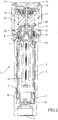
- an underground sprinkler 1 of the pop-up type is shown in the resting position and in the jet dispensing position, respectively, comprising an outer tubular body or main body 2 intended to be vertically inserted into the soil of the lawn, garden, or the like, for which the irrigation is required, and an inner body or piston 3 slidably inserted into said main body 2 so as to be lifted from the resting position in Fig. 1 to the jet dispensing position in Fig. 2 .
- the lifting of piston 3 is determined by the pressure of the water supplied, when desired, to the lower mouth 4 of the main body 2 from a suitable water supply system (of any known type).
- piston 3 to be returned into the main body 2 is determined, in the absence of water pressure, by a spring 5 arranged about piston 3 and acting between an outer lower edge 6 and a double upper ring 7, 8 hold in place by a ferrule 9 screwed at the top of the main body 2.
- the lower end of piston 3 is provided with a closing ring 10 with side windows 11, performing the double task of exploiting the water pressure to lift piston 3 and allowing, when the irrigation is completed, the water left inside piston 3 to outflow.
- a tubular filter 12 is located inside piston 3, serving to filter the water from the underground water supply system.
- a dispensing head 13 is secured at the top of piston 3, acting to dispense the water required to irrigate the surface of the surrounding soil in the shape of a circular jet.
- the dispensing head 13 has a lower part 14 forming a jet flow rate adjusting unit, and an upper part 15 forming the jet diffusing unit, here comprising a diffuser cylinder 16 freely rotatable abut a stationary pin 17, a counter-rotating fan 18 with respect to the diffuser cylinder 16 by virtue of a gearing, not shown in the drawings, and a cover member 19 secured at the top of pin 17.
- the present invention related to the position and structure of the jet flow rate adjusting unit is not to be meant as limited to the use with the jet diffusing unit shown in the drawings and described in EP 1 173 286 B1 . Indeed, the present invention is applicable to any jet dispensing head irrespective of the diffusion unit which is used.
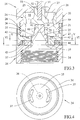
- the lower part 14 of the dispensing head 13 forming, as stated, the jet flow rate adjusting unit, is located with respect to the piston in a position so as to exit the footprint of the main body 2 during irrigation, thus being manually accessible from outside, as shown in Fig. 2 .
- the adjusting unit 14 is shown in an enlarged scale in Fig. 3 and comprises an upper body 20 secured to pin 17 and provided with a threaded lower part 21, an insert 22 snap-fitted into the upper body 20, an intermediate body 23 screwed onto the threaded part 21 of the upper body 20, and a lower body 24 screwed on the upper end of the piston 3.
- the upper body 20 is substantially overturned cup-shaped and has an axial hole 25 at the top.
- insert 22 in turn includes an annular peripheral wall 26 and a circular intermediate cross-bar 27 crossed by axial holes 28 which are arranged circumferentially, dividing the inner space of insert 22 into a lower cavity 29 and an upper cavity 30.
- insert 22 has an annular neck 31 with a central blind hole 32. Neck 31 is inserted into the hole 25 of the upper body 20 where, since it has a smaller diameter, it creates an annular slit 33. The lower end of pin 17 is forcedly pressed into the central blind hole 32.
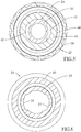
- the lower body 24 has an annular peripheral wall 34, internally threaded, from which a truncated cone, funnel-shaped central part 35 extends upward, ending in a closed neck 36.
- the truncated cone-shaped part 35 is crossed by two diametrically opposite elongated loops 37.
- the intermediate body 23 has an annular peripheral wall 38 with vertical outer grooves, a base 43, and a central part 39 surrounding the truncated cone-shaped part 35 of the lower body 24 and grabs thereon by inserting an annular projection 40 thereof into an annular valley 41 of said truncated cone-shaped part 35.
- the above-mentioned central part 39 is crossed by diametrically opposite loops 42, completely similar to the loops 37 of the lower body 24 and similarly arranged so as to overlap or not the loops 37 according to the angular position of the intermediate body 23.
- An O-ring 44 is interposed between the base 43 of the intermediate body 23 and the top of the wall 34 of the lower body 24 ( Fig. 3 ).
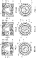
- FIGS. 8-13 Three possible angular positions of the intermediate body 23 with respect to the lower body 24, and hence of the loops 42 with respect to the loops 37, are shown in Figs. 8-13 .
- a different jet dispensing condition by the dispensing head 13 corresponds to each of them.
- the upper loops 42 partially match with the lower loops 37, so as to allow a limited water flow to pass, which through the lower cavity 29, the holes 28, and the upper cavity 30 of insert 22, and the slit 33, reaches the diffuser cylinder 16 which, through the inner passageways thereof, dispenses a coil-shaped flow radially directed by fan 19, as explained in EP 1 173 286 B .
- the described adjustment of the jet can be performed manually, with the dispensing head 13 in the lifted position in Fig. 2 .
Landscapes
- Nozzles (AREA)
Claims (4)
- Ausgabekopf (13) für einen Versenkregner (1) der Art umfassend einen rohrförmigen äußeren Hauptkörper (2), der dazu vorgesehen ist, unterirdisch vertikal vergraben zu werden, und einen inneren Körper oder bewegbaren Kolben (3), der verschiebbar in dem Hauptkörper (2) eingesetzt ist und mit einem Wasserausgabekopf (13) endet, der mit einer Verteilungseinheit (16, 17) versehen ist, wobei der Kolben (3) typischerweise federnd in einer Ruhestellung mit abgesenktem Kopf (13) desselben gehalten wird und durch einen Druck des zu der Basis des Hauptkörpers (2) zugeführten Wassers in die Bewässerungsstellung mit angehobenem Kopf (13) verlagerbar ist, wobei der Ausgabekopf (13) eine Strahleinstellungseinheit (14) aufweist, die an einer Stelle derart angeordnet ist, dass diese von außen manuell zugänglich ist, wenn der Kopf (13) in die Bewässerungsstellung angehoben ist, und der dadurch gekennzeichnet ist, dass die Einstellungseinheit (14) im Wesentlichen einen Drehringkörper oder Zwischenkörper (23) umfasst, der an einer dazwischenliegenden Stelle zwischen einem oberen Körper (20), der die Verteilungseinheit (16, 17) unterbaut, und einem unteren Körper (24) angeordnet ist, der für das Bewegen des Kopfes (13) an dem Kolben (3) gesichert ist, wobei der drehbare Zwischenkörper (23) mit wasserdurchlässigen Öffnungen (42) versehen ist, die durch Verändern der Winkelstellung des Zwischenkörpers (23) korrespondierende Öffnungen (37) des unteren Körpers (24) überlappen oder nicht überlappen können, um den Durchgang von Wasser von der Basis des Hauptkörpers (2) zu der Verteilungseinheit (16, 17) teilweise oder vollständig zu öffnen oder zu schließen, wobei in dem oberen Körper (20) ein Einsatz (22) verrastet ist, der eine ringförmige Umfangswand (26) und eine ringförmige, durch in Umfangsrichtung angeordnete axiale Löcher (28) durchsetzte Zwischentraverse (27) aufweist, die den Innenraum des Einsatzes (22) in eine untere Kavität (29) und eine obere Kavität (30) aufteilt, wobei der Einsatz (22) an der Oberseite mit einem ringförmigen Hals (31) mit einem zentralen Sackloch (32) endet, der in ein axial oberes Loch (25) des oberen Körpers (20) derart eingesetzt ist, dass ein diesen umgebender ringförmiger Spalt (33) definiert wird.
- Ausgabekopf (13) nach Anspruch 1, dadurch gekennzeichnet, dass der untere Körper (24) eine ringförmige Umfangswand (34), die auf die Oberseite des Kolbens (3) geschraubt werden kann, und einen kegelstumpfförmigen zentralen Teil (35) aufweist, der sich nach oben hin zu einem geschlossenen Hals (36) erstreckt, wobei der kegelstumpfförmige Teil (35) von zwei diametral entgegengesetzten, länglichen Öffnungen (37) durchsetzt wird.
- Ausgabekopf (13) nach Anspruch 2, dadurch gekennzeichnet, dass der Zwischenkörper (23) eine ringförmige Umfangswand (38) mit vertikalen äußeren Nuten, eine Basis (43) und einen zentralen Teil (39) aufweist, der den kegelstumpfförmigen Teil (35) des unteren Körpers (24) umgibt und greift, wobei der zentrale Teil (39) von diametral entgegengesetzten Öffnungen (42) durchsetzt ist, die völlig ähnlich den Öffnungen (37) des unteren Körpers (24) sind und ähnlich angeordnet sind, um entsprechend der Winkelstellung des Zwischenkörpers (23) die Öffnungen (37) zu überlappen oder nicht zu überlappen.
- Ausgabekopf (13) nach Anspruch 3, dadurch gekennzeichnet, dass zwischen der Basis (43) des Zwischenkörpers (23) und der Oberseite der Umfangswand (34) des unteren Körpers (24) ein O-Ring (44) zwischengefügt ist.
Applications Claiming Priority (1)
| Application Number | Priority Date | Filing Date | Title |
|---|---|---|---|
| ITMI20140165 | 2014-02-05 |
Publications (2)
| Publication Number | Publication Date |
|---|---|
| EP2907580A1 EP2907580A1 (de) | 2015-08-19 |
| EP2907580B1 true EP2907580B1 (de) | 2017-01-04 |
Family
ID=50440737
Family Applications (1)
| Application Number | Title | Priority Date | Filing Date |
|---|---|---|---|
| EP15153667.9A Active EP2907580B1 (de) | 2014-02-05 | 2015-02-03 | Ausgabekopf mit neuer durchflussbasierter Verstelleinheit für einen versenkbaren unterirdischen Sprinkler |
Country Status (3)
| Country | Link |
|---|---|
| US (1) | US9364844B2 (de) |
| EP (1) | EP2907580B1 (de) |
| ES (1) | ES2617573T3 (de) |
Families Citing this family (3)
| Publication number | Priority date | Publication date | Assignee | Title |
|---|---|---|---|---|
| CN106402407A (zh) * | 2016-09-30 | 2017-02-15 | 宋庆波 | 直埋式截止阀 |
| US20230082059A1 (en) * | 2021-09-16 | 2023-03-16 | Hunter Industries, Inc. | Nozzle turret with an accelerating stream conditioner for a rotating irrigation sprinkler |
| CN119387058B (zh) * | 2024-12-09 | 2025-10-17 | 昆明理工大学 | 一种多节高压弥散喷头 |
Family Cites Families (7)
| Publication number | Priority date | Publication date | Assignee | Title |
|---|---|---|---|---|
| US3088677A (en) | 1961-07-03 | 1963-05-07 | Anthony Mfg Corp | Oscillating arm pop-up sprinkler |
| IL119211A0 (en) | 1996-03-22 | 1996-12-05 | Lego Irrigation Ltd | Static sprinkler with presettable water discharge pattern |
| US5749518A (en) * | 1996-05-21 | 1998-05-12 | Eiko Electric Products Corp. | Adjustable multi-pattern miniature fountain sprinkler |
| IT1311812B1 (it) | 1999-01-18 | 2002-03-19 | Soledor Caffe Di Vendramini Da | Macchina da caffe' espresso, particolarmente del tipo in cialde. |
| IT1311912B1 (it) | 1999-04-07 | 2002-03-20 | Claber Spa | Testina di erogazione per irrigatore sotterraneo a scomparsa. |
| IT1316664B1 (it) | 2000-02-24 | 2003-04-24 | Claber Spa | Testina di erogazione multigetto ad elementi controrotanti perirrigatore sotterraneo a scomparsa |
| US7429005B2 (en) * | 2004-02-02 | 2008-09-30 | Orbit Irrigation Products, Inc. | Adjustable spray pattern sprinkler |
-
2015
- 2015-02-03 ES ES15153667.9T patent/ES2617573T3/es active Active
- 2015-02-03 EP EP15153667.9A patent/EP2907580B1/de active Active
- 2015-02-05 US US14/614,466 patent/US9364844B2/en active Active
Non-Patent Citations (1)
| Title |
|---|
| None * |
Also Published As
| Publication number | Publication date |
|---|---|
| ES2617573T3 (es) | 2017-06-19 |
| US20150217321A1 (en) | 2015-08-06 |
| EP2907580A1 (de) | 2015-08-19 |
| US9364844B2 (en) | 2016-06-14 |
Similar Documents
| Publication | Publication Date | Title |
|---|---|---|
| US11684939B2 (en) | Sprinkler with internal compartments | |
| US8297533B2 (en) | Rotary stream sprinkler with adjustable arc orifice plate | |
| EP2251090A2 (de) | Sprinklervorrichtung mit variabler Reichweite und Verfahren für Muster für Sprinkler mit variabler Reichweite | |
| US7322533B2 (en) | Rotary stream sprinkler with adjustable deflector ring | |
| EP2907580B1 (de) | Ausgabekopf mit neuer durchflussbasierter Verstelleinheit für einen versenkbaren unterirdischen Sprinkler | |
| US8955767B1 (en) | Rotor-type irrigation sprinkler with coarse and fine arc adjustment | |
| AU678860B2 (en) | Multifunction delivery unit for irrigation pistol | |
| US9156043B2 (en) | Arc adjustable rotary sprinkler with automatic matched precipitation | |
| KR101665289B1 (ko) | 분사각 조절이 가능한 스피드 스프레이어용 분사노즐 | |
| US10232388B2 (en) | Multiple orientation rotatable sprinkler | |
| US20120132727A1 (en) | Dual Trajectory Nozzle for Rotor-Type Sprinkler | |
| US20120205467A1 (en) | Irrigation Sprinkler With Adjustable Nozzle Trajectory | |
| US10758923B1 (en) | Irrigation devices and methods | |
| US20140042251A1 (en) | Lawn sprinkler flow control device | |
| JP2018082384A (ja) | 屋外用監視カメラ | |
| US20150351332A1 (en) | Sprinkler Flow Valves | |
| EP2007528B1 (de) | Versenkregner | |
| CA2919455C (en) | Sprinkler | |
| WO2016153529A1 (en) | Sprinkler head nozzle assembly with adjustable arc, flow rate and stream angle | |
| US20190224698A1 (en) | Sprinkler with adjustable area of coverage | |
| US10322421B2 (en) | Sprinkler | |
| CN104190565B (zh) | 旋转射线喷头 | |
| KR20170122626A (ko) | 회전 분출형 농업용수 공급 호스 | |
| JP6602589B2 (ja) | 柱状散水装置及び散水機能付き水栓柱 | |
| KR200488613Y1 (ko) | 농수로 개폐장치 |
Legal Events
| Date | Code | Title | Description |
|---|---|---|---|
| PUAI | Public reference made under article 153(3) epc to a published international application that has entered the european phase |
Free format text: ORIGINAL CODE: 0009012 |
|
| AK | Designated contracting states |
Kind code of ref document: A1 Designated state(s): AL AT BE BG CH CY CZ DE DK EE ES FI FR GB GR HR HU IE IS IT LI LT LU LV MC MK MT NL NO PL PT RO RS SE SI SK SM TR |
|
| AX | Request for extension of the european patent |
Extension state: BA ME |
|
| 17P | Request for examination filed |
Effective date: 20160216 |
|
| RBV | Designated contracting states (corrected) |
Designated state(s): AL AT BE BG CH CY CZ DE DK EE ES FI FR GB GR HR HU IE IS IT LI LT LU LV MC MK MT NL NO PL PT RO RS SE SI SK SM TR |
|
| RIC1 | Information provided on ipc code assigned before grant |
Ipc: B05B 1/30 20060101AFI20160616BHEP Ipc: B05B 15/10 20060101ALI20160616BHEP Ipc: B05B 1/26 20060101ALN20160616BHEP Ipc: B05B 3/02 20060101ALI20160616BHEP |
|
| GRAP | Despatch of communication of intention to grant a patent |
Free format text: ORIGINAL CODE: EPIDOSNIGR1 |
|
| INTG | Intention to grant announced |
Effective date: 20160728 |
|
| GRAS | Grant fee paid |
Free format text: ORIGINAL CODE: EPIDOSNIGR3 |
|
| GRAA | (expected) grant |
Free format text: ORIGINAL CODE: 0009210 |
|
| AK | Designated contracting states |
Kind code of ref document: B1 Designated state(s): AL AT BE BG CH CY CZ DE DK EE ES FI FR GB GR HR HU IE IS IT LI LT LU LV MC MK MT NL NO PL PT RO RS SE SI SK SM TR |
|
| REG | Reference to a national code |
Ref country code: GB Ref legal event code: FG4D |
|
| REG | Reference to a national code |
Ref country code: CH Ref legal event code: EP |
|
| REG | Reference to a national code |
Ref country code: AT Ref legal event code: REF Ref document number: 858713 Country of ref document: AT Kind code of ref document: T Effective date: 20170115 |
|
| REG | Reference to a national code |
Ref country code: IE Ref legal event code: FG4D |
|
| REG | Reference to a national code |
Ref country code: FR Ref legal event code: PLFP Year of fee payment: 3 |
|
| REG | Reference to a national code |
Ref country code: DE Ref legal event code: R096 Ref document number: 602015001162 Country of ref document: DE |
|
| REG | Reference to a national code |
Ref country code: LT Ref legal event code: MG4D Ref country code: NL Ref legal event code: MP Effective date: 20170104 |
|
| PG25 | Lapsed in a contracting state [announced via postgrant information from national office to epo] |
Ref country code: BE Free format text: LAPSE BECAUSE OF NON-PAYMENT OF DUE FEES Effective date: 20170228 |
|
| REG | Reference to a national code |
Ref country code: AT Ref legal event code: MK05 Ref document number: 858713 Country of ref document: AT Kind code of ref document: T Effective date: 20170104 |
|
| REG | Reference to a national code |
Ref country code: ES Ref legal event code: FG2A Ref document number: 2617573 Country of ref document: ES Kind code of ref document: T3 Effective date: 20170619 |
|
| PG25 | Lapsed in a contracting state [announced via postgrant information from national office to epo] |
Ref country code: NL Free format text: LAPSE BECAUSE OF FAILURE TO SUBMIT A TRANSLATION OF THE DESCRIPTION OR TO PAY THE FEE WITHIN THE PRESCRIBED TIME-LIMIT Effective date: 20170104 |
|
| PG25 | Lapsed in a contracting state [announced via postgrant information from national office to epo] |
Ref country code: FI Free format text: LAPSE BECAUSE OF FAILURE TO SUBMIT A TRANSLATION OF THE DESCRIPTION OR TO PAY THE FEE WITHIN THE PRESCRIBED TIME-LIMIT Effective date: 20170104 Ref country code: LT Free format text: LAPSE BECAUSE OF FAILURE TO SUBMIT A TRANSLATION OF THE DESCRIPTION OR TO PAY THE FEE WITHIN THE PRESCRIBED TIME-LIMIT Effective date: 20170104 Ref country code: IS Free format text: LAPSE BECAUSE OF FAILURE TO SUBMIT A TRANSLATION OF THE DESCRIPTION OR TO PAY THE FEE WITHIN THE PRESCRIBED TIME-LIMIT Effective date: 20170504 Ref country code: HR Free format text: LAPSE BECAUSE OF FAILURE TO SUBMIT A TRANSLATION OF THE DESCRIPTION OR TO PAY THE FEE WITHIN THE PRESCRIBED TIME-LIMIT Effective date: 20170104 Ref country code: GR Free format text: LAPSE BECAUSE OF FAILURE TO SUBMIT A TRANSLATION OF THE DESCRIPTION OR TO PAY THE FEE WITHIN THE PRESCRIBED TIME-LIMIT Effective date: 20170405 Ref country code: NO Free format text: LAPSE BECAUSE OF FAILURE TO SUBMIT A TRANSLATION OF THE DESCRIPTION OR TO PAY THE FEE WITHIN THE PRESCRIBED TIME-LIMIT Effective date: 20170404 |
|
| PG25 | Lapsed in a contracting state [announced via postgrant information from national office to epo] |
Ref country code: LV Free format text: LAPSE BECAUSE OF FAILURE TO SUBMIT A TRANSLATION OF THE DESCRIPTION OR TO PAY THE FEE WITHIN THE PRESCRIBED TIME-LIMIT Effective date: 20170104 Ref country code: AT Free format text: LAPSE BECAUSE OF FAILURE TO SUBMIT A TRANSLATION OF THE DESCRIPTION OR TO PAY THE FEE WITHIN THE PRESCRIBED TIME-LIMIT Effective date: 20170104 Ref country code: PT Free format text: LAPSE BECAUSE OF FAILURE TO SUBMIT A TRANSLATION OF THE DESCRIPTION OR TO PAY THE FEE WITHIN THE PRESCRIBED TIME-LIMIT Effective date: 20170504 Ref country code: PL Free format text: LAPSE BECAUSE OF FAILURE TO SUBMIT A TRANSLATION OF THE DESCRIPTION OR TO PAY THE FEE WITHIN THE PRESCRIBED TIME-LIMIT Effective date: 20170104 Ref country code: BG Free format text: LAPSE BECAUSE OF FAILURE TO SUBMIT A TRANSLATION OF THE DESCRIPTION OR TO PAY THE FEE WITHIN THE PRESCRIBED TIME-LIMIT Effective date: 20170404 Ref country code: RS Free format text: LAPSE BECAUSE OF FAILURE TO SUBMIT A TRANSLATION OF THE DESCRIPTION OR TO PAY THE FEE WITHIN THE PRESCRIBED TIME-LIMIT Effective date: 20170104 Ref country code: SE Free format text: LAPSE BECAUSE OF FAILURE TO SUBMIT A TRANSLATION OF THE DESCRIPTION OR TO PAY THE FEE WITHIN THE PRESCRIBED TIME-LIMIT Effective date: 20170104 |
|
| REG | Reference to a national code |
Ref country code: DE Ref legal event code: R119 Ref document number: 602015001162 Country of ref document: DE |
|
| PG25 | Lapsed in a contracting state [announced via postgrant information from national office to epo] |
Ref country code: RO Free format text: LAPSE BECAUSE OF FAILURE TO SUBMIT A TRANSLATION OF THE DESCRIPTION OR TO PAY THE FEE WITHIN THE PRESCRIBED TIME-LIMIT Effective date: 20170104 Ref country code: CZ Free format text: LAPSE BECAUSE OF FAILURE TO SUBMIT A TRANSLATION OF THE DESCRIPTION OR TO PAY THE FEE WITHIN THE PRESCRIBED TIME-LIMIT Effective date: 20170104 Ref country code: SK Free format text: LAPSE BECAUSE OF FAILURE TO SUBMIT A TRANSLATION OF THE DESCRIPTION OR TO PAY THE FEE WITHIN THE PRESCRIBED TIME-LIMIT Effective date: 20170104 Ref country code: EE Free format text: LAPSE BECAUSE OF FAILURE TO SUBMIT A TRANSLATION OF THE DESCRIPTION OR TO PAY THE FEE WITHIN THE PRESCRIBED TIME-LIMIT Effective date: 20170104 |
|
| PLBE | No opposition filed within time limit |
Free format text: ORIGINAL CODE: 0009261 |
|
| STAA | Information on the status of an ep patent application or granted ep patent |
Free format text: STATUS: NO OPPOSITION FILED WITHIN TIME LIMIT |
|
| REG | Reference to a national code |
Ref country code: IE Ref legal event code: MM4A |
|
| PG25 | Lapsed in a contracting state [announced via postgrant information from national office to epo] |
Ref country code: SM Free format text: LAPSE BECAUSE OF FAILURE TO SUBMIT A TRANSLATION OF THE DESCRIPTION OR TO PAY THE FEE WITHIN THE PRESCRIBED TIME-LIMIT Effective date: 20170104 Ref country code: DK Free format text: LAPSE BECAUSE OF FAILURE TO SUBMIT A TRANSLATION OF THE DESCRIPTION OR TO PAY THE FEE WITHIN THE PRESCRIBED TIME-LIMIT Effective date: 20170104 Ref country code: MC Free format text: LAPSE BECAUSE OF FAILURE TO SUBMIT A TRANSLATION OF THE DESCRIPTION OR TO PAY THE FEE WITHIN THE PRESCRIBED TIME-LIMIT Effective date: 20170104 |
|
| PG25 | Lapsed in a contracting state [announced via postgrant information from national office to epo] |
Ref country code: LU Free format text: LAPSE BECAUSE OF NON-PAYMENT OF DUE FEES Effective date: 20170203 |
|
| REG | Reference to a national code |
Ref country code: FR Ref legal event code: PLFP Year of fee payment: 4 |
|
| PG25 | Lapsed in a contracting state [announced via postgrant information from national office to epo] |
Ref country code: DE Free format text: LAPSE BECAUSE OF NON-PAYMENT OF DUE FEES Effective date: 20170901 |
|
| REG | Reference to a national code |
Ref country code: BE Ref legal event code: MM Effective date: 20170228 |
|
| PG25 | Lapsed in a contracting state [announced via postgrant information from national office to epo] |
Ref country code: SI Free format text: LAPSE BECAUSE OF FAILURE TO SUBMIT A TRANSLATION OF THE DESCRIPTION OR TO PAY THE FEE WITHIN THE PRESCRIBED TIME-LIMIT Effective date: 20170104 Ref country code: IE Free format text: LAPSE BECAUSE OF NON-PAYMENT OF DUE FEES Effective date: 20170203 |
|
| REG | Reference to a national code |
Ref country code: CH Ref legal event code: PL |
|
| PG25 | Lapsed in a contracting state [announced via postgrant information from national office to epo] |
Ref country code: MT Free format text: LAPSE BECAUSE OF NON-PAYMENT OF DUE FEES Effective date: 20170203 |
|
| PG25 | Lapsed in a contracting state [announced via postgrant information from national office to epo] |
Ref country code: CH Free format text: LAPSE BECAUSE OF NON-PAYMENT OF DUE FEES Effective date: 20180228 Ref country code: LI Free format text: LAPSE BECAUSE OF NON-PAYMENT OF DUE FEES Effective date: 20180228 |
|
| PG25 | Lapsed in a contracting state [announced via postgrant information from national office to epo] |
Ref country code: HU Free format text: LAPSE BECAUSE OF FAILURE TO SUBMIT A TRANSLATION OF THE DESCRIPTION OR TO PAY THE FEE WITHIN THE PRESCRIBED TIME-LIMIT; INVALID AB INITIO Effective date: 20150203 |
|
| PG25 | Lapsed in a contracting state [announced via postgrant information from national office to epo] |
Ref country code: CY Free format text: LAPSE BECAUSE OF FAILURE TO SUBMIT A TRANSLATION OF THE DESCRIPTION OR TO PAY THE FEE WITHIN THE PRESCRIBED TIME-LIMIT Effective date: 20170104 |
|
| PG25 | Lapsed in a contracting state [announced via postgrant information from national office to epo] |
Ref country code: MK Free format text: LAPSE BECAUSE OF FAILURE TO SUBMIT A TRANSLATION OF THE DESCRIPTION OR TO PAY THE FEE WITHIN THE PRESCRIBED TIME-LIMIT Effective date: 20170104 |
|
| PG25 | Lapsed in a contracting state [announced via postgrant information from national office to epo] |
Ref country code: TR Free format text: LAPSE BECAUSE OF FAILURE TO SUBMIT A TRANSLATION OF THE DESCRIPTION OR TO PAY THE FEE WITHIN THE PRESCRIBED TIME-LIMIT Effective date: 20170104 |
|
| PG25 | Lapsed in a contracting state [announced via postgrant information from national office to epo] |
Ref country code: AL Free format text: LAPSE BECAUSE OF FAILURE TO SUBMIT A TRANSLATION OF THE DESCRIPTION OR TO PAY THE FEE WITHIN THE PRESCRIBED TIME-LIMIT Effective date: 20170104 |
|
| P01 | Opt-out of the competence of the unified patent court (upc) registered |
Effective date: 20230421 |
|
| PGFP | Annual fee paid to national office [announced via postgrant information from national office to epo] |
Ref country code: ES Payment date: 20250331 Year of fee payment: 11 |
|
| PGFP | Annual fee paid to national office [announced via postgrant information from national office to epo] |
Ref country code: GB Payment date: 20260219 Year of fee payment: 12 |
|
| PGFP | Annual fee paid to national office [announced via postgrant information from national office to epo] |
Ref country code: IT Payment date: 20260224 Year of fee payment: 12 |
|
| PGFP | Annual fee paid to national office [announced via postgrant information from national office to epo] |
Ref country code: FR Payment date: 20260218 Year of fee payment: 12 |