EP2907585B1 - Verfahren und Vorrichtung zum Auftragen eines Fluids auf eine Oberfläche eines Bauteils - Google Patents
Verfahren und Vorrichtung zum Auftragen eines Fluids auf eine Oberfläche eines Bauteils Download PDFInfo
- Publication number
- EP2907585B1 EP2907585B1 EP15154481.4A EP15154481A EP2907585B1 EP 2907585 B1 EP2907585 B1 EP 2907585B1 EP 15154481 A EP15154481 A EP 15154481A EP 2907585 B1 EP2907585 B1 EP 2907585B1
- Authority
- EP
- European Patent Office
- Prior art keywords
- component
- coating system
- mounts
- base plate
- component mounts
- Prior art date
- Legal status (The legal status is an assumption and is not a legal conclusion. Google has not performed a legal analysis and makes no representation as to the accuracy of the status listed.)
- Active
Links
Images

Classifications
-
- B—PERFORMING OPERATIONS; TRANSPORTING
- B05—SPRAYING OR ATOMISING IN GENERAL; APPLYING FLUENT MATERIALS TO SURFACES, IN GENERAL
- B05C—APPARATUS FOR APPLYING FLUENT MATERIALS TO SURFACES, IN GENERAL
- B05C13/00—Means for manipulating or holding work, e.g. for separate articles
- B05C13/02—Means for manipulating or holding work, e.g. for separate articles for particular articles
-
- B—PERFORMING OPERATIONS; TRANSPORTING
- B05—SPRAYING OR ATOMISING IN GENERAL; APPLYING FLUENT MATERIALS TO SURFACES, IN GENERAL
- B05B—SPRAYING APPARATUS; ATOMISING APPARATUS; NOZZLES
- B05B12/00—Arrangements for controlling delivery; Arrangements for controlling the spray area
- B05B12/08—Arrangements for controlling delivery; Arrangements for controlling the spray area responsive to condition of liquid or other fluent material to be discharged, of ambient medium or of target ; responsive to condition of spray devices or of supply means, e.g. pipes, pumps or their drive means
- B05B12/12—Arrangements for controlling delivery; Arrangements for controlling the spray area responsive to condition of liquid or other fluent material to be discharged, of ambient medium or of target ; responsive to condition of spray devices or of supply means, e.g. pipes, pumps or their drive means responsive to conditions of ambient medium or target, e.g. humidity, temperature position or movement of the target relative to the spray apparatus
- B05B12/122—Arrangements for controlling delivery; Arrangements for controlling the spray area responsive to condition of liquid or other fluent material to be discharged, of ambient medium or of target ; responsive to condition of spray devices or of supply means, e.g. pipes, pumps or their drive means responsive to conditions of ambient medium or target, e.g. humidity, temperature position or movement of the target relative to the spray apparatus responsive to presence or shape of target
-
- B—PERFORMING OPERATIONS; TRANSPORTING
- B05—SPRAYING OR ATOMISING IN GENERAL; APPLYING FLUENT MATERIALS TO SURFACES, IN GENERAL
- B05B—SPRAYING APPARATUS; ATOMISING APPARATUS; NOZZLES
- B05B13/00—Machines or plants for applying liquids or other fluent materials to surfaces of objects or other work by spraying, not covered by groups B05B1/00 - B05B11/00
- B05B13/02—Means for supporting work; Arrangement or mounting of spray heads; Adaptation or arrangement of means for feeding work
- B05B13/0285—Stands for supporting individual articles to be sprayed, e.g. doors, vehicle body parts
-
- B—PERFORMING OPERATIONS; TRANSPORTING
- B05—SPRAYING OR ATOMISING IN GENERAL; APPLYING FLUENT MATERIALS TO SURFACES, IN GENERAL
- B05B—SPRAYING APPARATUS; ATOMISING APPARATUS; NOZZLES
- B05B13/00—Machines or plants for applying liquids or other fluent materials to surfaces of objects or other work by spraying, not covered by groups B05B1/00 - B05B11/00
- B05B13/02—Means for supporting work; Arrangement or mounting of spray heads; Adaptation or arrangement of means for feeding work
- B05B13/04—Means for supporting work; Arrangement or mounting of spray heads; Adaptation or arrangement of means for feeding work the spray heads being moved during spraying operation
- B05B13/0431—Means for supporting work; Arrangement or mounting of spray heads; Adaptation or arrangement of means for feeding work the spray heads being moved during spraying operation with spray heads moved by robots or articulated arms, e.g. for applying liquid or other fluent material to three-dimensional [3D] surfaces
-
- B—PERFORMING OPERATIONS; TRANSPORTING
- B05—SPRAYING OR ATOMISING IN GENERAL; APPLYING FLUENT MATERIALS TO SURFACES, IN GENERAL
- B05C—APPARATUS FOR APPLYING FLUENT MATERIALS TO SURFACES, IN GENERAL
- B05C5/00—Apparatus in which liquid or other fluent material is projected, poured or allowed to flow on to the surface of the work
- B05C5/02—Apparatus in which liquid or other fluent material is projected, poured or allowed to flow on to the surface of the work the liquid or other fluent material being discharged through an outlet orifice by pressure, e.g. from an outlet device in contact or almost in contact, with the work
- B05C5/0208—Apparatus in which liquid or other fluent material is projected, poured or allowed to flow on to the surface of the work the liquid or other fluent material being discharged through an outlet orifice by pressure, e.g. from an outlet device in contact or almost in contact, with the work for applying liquid or other fluent material to separate articles
- B05C5/0212—Apparatus in which liquid or other fluent material is projected, poured or allowed to flow on to the surface of the work the liquid or other fluent material being discharged through an outlet orifice by pressure, e.g. from an outlet device in contact or almost in contact, with the work for applying liquid or other fluent material to separate articles only at particular parts of the articles
- B05C5/0216—Apparatus in which liquid or other fluent material is projected, poured or allowed to flow on to the surface of the work the liquid or other fluent material being discharged through an outlet orifice by pressure, e.g. from an outlet device in contact or almost in contact, with the work for applying liquid or other fluent material to separate articles only at particular parts of the articles by relative movement of article and outlet according to a predetermined path
-
- B—PERFORMING OPERATIONS; TRANSPORTING
- B05—SPRAYING OR ATOMISING IN GENERAL; APPLYING FLUENT MATERIALS TO SURFACES, IN GENERAL
- B05B—SPRAYING APPARATUS; ATOMISING APPARATUS; NOZZLES
- B05B12/00—Arrangements for controlling delivery; Arrangements for controlling the spray area
-
- B—PERFORMING OPERATIONS; TRANSPORTING
- B05—SPRAYING OR ATOMISING IN GENERAL; APPLYING FLUENT MATERIALS TO SURFACES, IN GENERAL
- B05D—PROCESSES FOR APPLYING FLUENT MATERIALS TO SURFACES, IN GENERAL
- B05D1/00—Processes for applying liquids or other fluent materials
- B05D1/26—Processes for applying liquids or other fluent materials performed by applying the liquid or other fluent material from an outlet device in contact with, or almost in contact with, the surface
-
- B—PERFORMING OPERATIONS; TRANSPORTING
- B23—MACHINE TOOLS; METAL-WORKING NOT OTHERWISE PROVIDED FOR
- B23Q—DETAILS, COMPONENTS, OR ACCESSORIES FOR MACHINE TOOLS, e.g. ARRANGEMENTS FOR COPYING OR CONTROLLING; MACHINE TOOLS IN GENERAL CHARACTERISED BY THE CONSTRUCTION OF PARTICULAR DETAILS OR COMPONENTS; COMBINATIONS OR ASSOCIATIONS OF METAL-WORKING MACHINES, NOT DIRECTED TO A PARTICULAR RESULT
- B23Q17/00—Arrangements for observing, indicating or measuring on machine tools
- B23Q17/002—Arrangements for observing, indicating or measuring on machine tools for indicating or measuring the holding action of work or tool holders
- B23Q17/003—Arrangements for observing, indicating or measuring on machine tools for indicating or measuring the holding action of work or tool holders by measuring a position
-
- B—PERFORMING OPERATIONS; TRANSPORTING
- B23—MACHINE TOOLS; METAL-WORKING NOT OTHERWISE PROVIDED FOR
- B23Q—DETAILS, COMPONENTS, OR ACCESSORIES FOR MACHINE TOOLS, e.g. ARRANGEMENTS FOR COPYING OR CONTROLLING; MACHINE TOOLS IN GENERAL CHARACTERISED BY THE CONSTRUCTION OF PARTICULAR DETAILS OR COMPONENTS; COMBINATIONS OR ASSOCIATIONS OF METAL-WORKING MACHINES, NOT DIRECTED TO A PARTICULAR RESULT
- B23Q3/00—Devices holding, supporting, or positioning work or tools, of a kind normally removable from the machine
- B23Q3/02—Devices holding, supporting, or positioning work or tools, of a kind normally removable from the machine for mounting on a work-table, tool-slide, or analogous part
- B23Q3/06—Work-clamping means
- B23Q3/062—Work-clamping means adapted for holding workpieces having a special form or being made from a special material
Definitions
- the present invention relates to a method for applying a fluid to a surface of a component, wherein the component is arranged on a plurality of component holders in a computer-controlled coating system, detects the position of the component and applies the fluid to the surface of the component according to a preprogrammed coating profile.
- a computer-controlled coating plant of this kind is in WO2013 / 175392 A1 disclosed.
- the computer-controlled coating systems are usually CNC systems in which complex sealing courses along the contour of the joining surfaces are applied to the component with high precision by means of three-dimensionally controllable metering systems can.
- CNC systems in which complex sealing courses along the contour of the joining surfaces are applied to the component with high precision by means of three-dimensionally controllable metering systems can.
- automated application of the fluid precise positioning of the component in the coating system is essential.
- interchangeable base plates are usually produced for each component on which pin-like component holders are firmly mounted, in which the component to be coated are used.
- Each baseplate usually has a specific plug or socket so that the baseplate can be connected to the CNC controller via an electrical plug connection.
- the coating system thus recognizes which specific base plate is currently installed. By detecting the base plate, the controller also detects the position of the component to be coated. Accordingly, the respective coating program can be selected and the component can be exactly approached with the dosing head in order to apply a bead of the fluid to the surface in accordance with the desired course of the seal.
- the present invention is therefore based on the technical problem of providing a method for applying a fluid to a surface of a component, which is cheaper and therefore particularly suitable for small and pre-series production.
- the invention thus relates to a method for applying a fluid to a surface of a component, wherein the component is arranged on a plurality of component receptacles in a computer-controlled coating system, the position of the component detects and applies the fluid according to a preprogrammed coating profile on the surface of the component.
- the inventive method is characterized in that at least one of the component receptacles is mounted freely positionable on a base plate.
- component holders are sufficient for a stable arrangement of the component in the coating system.
- component receptacles may be provided, for example, four or five component holders.
- a component receptacle is firmly connected to the base plate, while the remaining component receptacles can be mounted freely positionable.
- the position of the permanently mounted component receptacle can identify, for example, different base plates, so that the coating system can also recognize without electrical plug connection, which base plate is currently mounted.
- the component is particularly preferably arranged by means of three to five freely positionable component holders, in particular by means of three or four freely positionable component holders, in the coating system.
- At least one component receptacle is height-adjustable.
- all component receptacles are height adjustable. Due to the height adjustability of the component holders, a specific position of the surface to be coated can be defined in space. Often it is necessary, for example, that the surface to be coated is aligned as exactly as possible horizontally. To determine the altitude of the surface to be coated of the component can height-adjustable gauges are used, which ensure the flatness and the constant component height.
- the component receptacles are freely positionable on the base plate, on the other hand, after setting a specific position, later slippage of the component receptacles must be precluded.
- the component holders are therefore also arrested or fixable on the base plate.
- a particularly simple locking / fixing of the component receptacles is ensured for example by the fact that the base plate consists of a ferromagnetic material and the component receptacles are each provided with magnetic feet.
- the magnetic feet may, for example, comprise a mechanical switch which switches a rotatable permanent magnet arranged in the magnetic base so that the magnetic feet can either adhere to the base plate or be detached therefrom. The operator can therefore very quickly and reliably switch between loosening and fixing the component.
- each component holder can be provided, for example, with an indexing pin, which engages in a predetermined opening or depression in the component, so that the component is precisely fixed at this point.
- Another head part may be formed as a support pin on which the component rests on a locally not exactly defined position.
- At least two of the component holders used should be equipped with an index pin so that the exact position of the component is set parallel to the plane of the base plate.
- the component receptacle can also be designed such that the component receptacle acts as a support element without an index pin.
- a detection pin can be provided, with the aid of which the exact position of the component holder can be detected or set up.
- the arrangement and position detection of the component takes place in the coating system in that arranging the component receptacles at predetermined locations on the base plate.
- the component can be certain coordinates stored for the nominal positions of the component receptacles in the computer-controlled coating system.
- This target position of the component receptacles on the base plate can then be displayed, for example, by an optical positioning device, so that the operating personnel can position the component receptacle accordingly.
- the exact position of the respective component holder is detected and / or displayed by means of a laser beam.
- the coating installation has a laser positioning device which emits a laser beam perpendicularly in the direction of the base plate and detects the reflected light by means of a detector.
- the component holder is provided for accurate positioning with a detection pin whose top is formed by a plate-like disc, in the center of a recess with a diameter in the desired positioning accuracy is recessed.
- the detector in the laser positioning device detects a reflection of the laser beam when it hits the disc of the detection pin outside the depression. As soon as the component holder is exactly positioned by the operator, the laser beam disappears into the recess in the center of the disk.
- the detector detects this by drastically reducing the intensity of the reflected light or, if the bottom of the well is mirrored, by drastically increasing the intensity of the reflected light.
- the system then signals the correct positioning to the operating personnel so that the operating personnel can fix the component holder in this position on the base plate. This positioning is carried out successively for all freely positionable component holders. After exact positioning of the component receptacles, the head part is in each case according to the requirements of the respective component against an index pin or a support pin or serves after removal of the detection pin itself as a component support.
- the exact position of the respective component holder is detected and / or displayed by means of a mechanical position sensor.
- the nominal positions of the component receptacles can be determined on the basis of digitized models of the respective components to be coated, taking into account, if appropriate, the desired coating course, calculated and displayed.
- the setpoint positions of the component receptacles for a new component to be coated can also be detected by means of the optical positioning device, the laser positioning device.
- the operator first arranges the new component to be coated on three to five component receptacles in the desired orientation and height on the base plate. Subsequently, the component is removed and the index pins and / or support pins of the component holders are replaced by detection pins.
- the operator positions the laser on the individual component receptacles so that the laser beam strikes in each case in the recess of the detection pin. As soon as the system signals the correct positioning of the laser, this position is saved as the target position of the respective component holder.
- the invention also provides a computer-controlled coating system for applying a fluid to a surface of a component having at least one base plate on which a plurality of component receptacles are freely positionable, at least one movable dosing head for applying the fluid to the surface of the component and at least one device for detecting the Target positions of the component holders and / or for displaying the desired positions of the component holders.
- FIG. 1 shows a schematic representation of the essential components of a coating system 10 according to the invention, with which a fluid from a (not shown) reservoir can be applied by means of a movable dosing tip 11 on the surface 12 of a component 13.
- the metering tip 11 is movable in the example shown by means of a first drive 14 in the x and z directions, while a second drive 15 ensures movement of the mounted on a ferromagnetic base plate 16 component 13 in the y direction.
- the metering tip 11 can apply an arbitrarily complex fluid course to the surface 12 of the component 13.
- a sealant can be applied along the contour of a housing half, for example a motor housing.
- the component 13 is mounted on four component receptacles 17, 18, 19, 20.
- Each component receptacle has magnetic feet 17a, 18a, 19a, 20a, so that the component receptacles on the one hand on the ferromagnetic base plates 16 are freely movable, on the other hand, however, if necessary, also on the base plate 16 can be fixed.
- FIG. 2 is the base plate 16 with the component holders 17, 18, 19, 20 without the in FIG. 1 shown component 13 shown in more detail.
- the dosing tip 11 is arranged in an application head 23 connected to the drive 4, which also comprises an optical positioning device.
- the optical positioning device emits a laser beam 24 in the direction of the base plate, the reflections of which are detected by a detector (not shown) arranged on the underside of the application head 23.
- the laser beam 24 can thus mark, for example, predetermined positions for the component receptacles on the base plate 16.
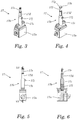
- FIG. 3 the component receptacle 17 is shown in more detail.
- the sleeve assembly 17b consists of an outer sleeve 17c and an inner sleeve 17d, in which in.
- an index pin 17e is inserted.
- a detection pin 17f 17e is inserted into the telescopic sleeve assembly 17b instead of the index pin.
- the variant with the index pin is used for accurate positioning of the component, wherein the index pin engages in an opening or depression on the underside of the component 13. If the detection pin 17f inserted into the telescopic sleeve assembly 17b, so the position of the component holder 17 can be accurately determined or precisely defined. Without index pin 17e or detection pin 17f is the flat top of the inner sleeve 17d in the example shown as a component support.
- the positioning of the component holder 17 takes place by means of the inserted detection pin 17f as follows:
- the laser is positioned on the base plate 16 by means of the drives 14 and 15 at the desired position of the respective component holder.
- the operating personnel then positioned the component holder 17 with inserted detection pin 17f roughly below the laser beam 24.
- For the fine positioning of the detection pin 17f on its upper side a flat disc 17g and a central bore 17h.
- the laser beam 24 strikes the flat disk 17g, the reflection of the laser beam 24 can be detected by the detector arranged in the application head 23.
- the intensity of the reflected light decreases drastically, which is detected by the evaluation electronics and signaled to the operating personnel as reaching the desired position, so that the component holder can be fixed at this position by means of a magnetic base.
- the identification pins are replaced by index pins or the detection pins are removed so that the component holders act as component supports.
- the procedure is correspondingly reversed: after the component 13 has been arranged in the desired manner by means of the component holders 17-20 on the base plate 16, the component holders are obtained 17 - 20 fixed on the base plate. Subsequently, the component to be coated 13 is removed and used detection pins in the component holders. Then, the laser beam 24 is controlled via the drive means 14 and 15 so that the laser beam 24 hits exactly in the bore of the respective component receiving. These positions are stored as nominal positions of the respective component receptacle 17-20.
- FIGS. 5 and 6 is the component holder 17 of FIG. 3 in the side view or in a cross section along the line VI-VI of FIG. 5 shown.
- the inner sleeve 17d is loaded upward by means of a spring 17i and can be fixed by means of a knurled screw 17j.
- the index pin 17e is thus pressed upward over the spring-loaded inner sleeve 17d until the upper side of the component 13 comes into abutment against the lower edges 21a and 22a of the gauges 21 and 21, respectively.
- the height of the component at different positions along the contour of the top of the component can be precisely determined.
- the position of the slidable inner sleeve 17d of the telescopic sleeve assembly 17b is fixed by tightening the knurled screw 17j.
- FIGS. 7 to 12 a second variant of the coating system according to the invention is described in more detail. Elements which fulfill the same or similar function as elements already described in connection with the first embodiment of the Figures 1-6 are described below, with the same, but increased by 100 reference numeral and not further explained.
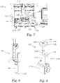
- FIG. 7 One recognizes a coating system 110, in which again a fluid is applied to the surface 112 of a component 113 with a movable dosing tip 111. It again recognizes two component receptacles 117, 118 in the foreground, on which the component 113 is mounted, wherein the component receptacles 117, 118 are each again positioned with magnetic feet 117a, 118a on a ferromagnetic base plate 116.
- the applicator head 123 of the second embodiment has a mechanical position sensor 125.
- the mechanical position sensor 125 serves both for detecting the target positions of the component holders during the initial setup a component to be coated, as well as for the display of the desired positions in the re-establishment of the component receptacles after a component change.
- the mechanical position sensor 125 has a sensor head 126, from the underside of which a movable pin 127 protrudes.
- a position sensor located in the interior of the sensor head 126 is designed so that at least three states of the pin 127 can be distinguished, namely a retracted position in which the pin is completely or almost completely pushed back into the interior of the sensor head, a partially extended position and a fully extended position in which the pin is extended out of the housing to a predetermined maximum length.
- the component holder is provided with a detection pin, which in the variant of FIGS. 7 to 12 is formed as a centering plate 117k.
- a detection pin which in the variant of FIGS. 7 to 12 is formed as a centering plate 117k.
- An exemplary component receptacle 117 with the centering plate 117k is shown in FIG FIG. 9 shown.
- a magnetic base 117a carrying a telescopically extendable sleeve assembly 117b.
- the sleeve assembly 117b consists of an outer sleeve 117c and an inner sleeve 117d. In the in FIG.
- the recognition plate 117k is used.
- the centering plate 117k has an opening 128, the underside of which is closed by a bottom 129.
- the inner diameter of the opening 128 is slightly larger than the outer diameter of the pin 127 of the mechanical position sensor 125, so that the pin 127 can engage in the opening 128, while other parts of the sensor head 126 of the mechanical position sensor 125 can not engage in the opening 128.
- the depth of the opening 128, that is, the distance of the top of the bottom plate 129 from the top of the centering plate 117k, is smaller than the maximum extension distance of the pin 127 from the sensor head 126.
- a rocker arm 117I is provided for fixing the height of the telescopically extendable sleeve assembly 117b instead of a thumbscrew, which defines the inner sleeve 117d in the desired position with respect to the outer sleeve 117c.
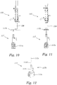
- the mechanical position sensor 125 cooperates with the centering plate 117k fastened in a component receptacle 117.
- the mechanical position sensor 125 has been computer-controlled placed at a predetermined location at which the component receptacle 117 is to be positioned.
- the operator picks up a component receptacle provided with a centering plate 117k and positions it with the magnetic base 117a under the mechanical position sensor 125 FIG. 10 shown position, the component holder is still next to the predetermined target position.
- the pin 127 protrudes maximally from the sensor head 126, so that the operator is signaled that the component holder is not yet in its intended position.
- the pin 127 comes against the surface 130 of the centering plate 117k in abutment and is completely pushed by the plate 117k in the sensor head 126. Also in this position, the operator is signaled that the component holder 117 is not yet at its intended location. Only when the component receptacle 117, as in FIG. 11 is located centrally below the detection pin 127, the detection pin can engage in the opening 128 of the centering plate 117k and assumes a partially extended position. In this position, for example, the operating personnel is visually and / or acoustically signaled that the component receptacle 117 is at its intended position. By switching on the magnetic foot 117a, the operator can then lock the component holder at the intended location.
- FIG. 12 Finally, it is indicated how the component receptacle 117 is converted so that the component 113 to be coated can be arranged on the component receptacle can.
- the in FIG. 12 already removed centering plate 117k removed and replaced by an index pin 117e.
- the index pin 117e is inserted into the inner sleeve 117d of the telescopically extendable sleeve arrangement 117b.
Landscapes
- Coating Apparatus (AREA)
- Engineering & Computer Science (AREA)
- Robotics (AREA)
Description
- Die vorliegende Erfindung betrifft ein Verfahren zum Auftragen eines Fluids auf eine Oberfläche eines Bauteils, wobei man das Bauteil auf mehreren Bauteilaufnahmen in einer computergesteuerten Beschichtungsanlage anordnet, die Position des Bauteils erfasst und das Fluid gemäß einem vorprogrammierten Beschichtsverlauf auf die Oberfläche des Bauteils aufträgt. Eine computergesteuerte Beschichtungsanlage dieser Art ist in
WO2013/175392 A1 offenbart. - Es ist bekannt, metallische Bauteile an deren Fügeflächen zu verkleben bzw. sie durch Flächendichtungen abzudichten. Beispielsweise werden in der Fahrzeugindustrie einzelne Bauteile des Motorblocks oder des Getriebes durch Klebedichtungen miteinander verbunden. Dazu wird in automatisierten Fertigungslinien eine flüssige bis pastöse Klebemasse mithilfe von Dosierrobotern als Raupe entlang der gewünschten Klebekontur auf eine Fügefläche des Bauteils aufgebracht. Anschließend werden die Bauteile entlang ihrer Fügeflächen aneinander gepresst und gegebenenfalls zusätzlich mittels Schraub- oder Klemmverbindungen miteinander verbunden. Als Dichtungs- oder Klebematerialien kommen dabei unterschiedlichste Ein- und Mehrkomponentenmaterialien zum Einsatz, beispielsweise Silicon-, Polyurethan-, Epoxidharzkleber, Hotmelts usw.
- Im Folgenden wird zwischen den Begriffen Kleben und Dichten nicht streng unterschieden, da in zahlreichen Anwendungsfällen meist beide Funktionen - gegebenenfalls unterschiedlich gewichtet - erwünscht sind. Wenn die zu verbindenden Bauteile durch weitere Verbindungsmittel, beispielsweise durch Schrauben, form- oder reibschlüssige Mittel, Schweißnähte usw., zusammengehalten werden, wird die Dichtungsfunktion im Vordergrund stehen. Es ist aber auch möglich, Bauteile mithilfe des erfindungsgemäßen Verfahrens zu verkleben, d.h. ohne zusätzliche mechanische Verbindungsmittel miteinander zu verbinden.
- Bei den computergesteuerten Beschichtungsanlagen im Sinne der vorliegenden Erfindung handelt es sich üblicherweise um CNC-Anlagen, bei denen mittels dreidimensional steuerbarer Dosieranlagen komplexe Dichtungsverläufe entlang der Kontur der Fügeflächen mit hoher Präzision auf das Bauteil aufgetragen werden können. Für die computergesteuerte, automatisierte Auftragung des Fluids ist eine genaue Positionierung des Bauteils in der Beschichtungsanlage unerlässlich.
- Gemäß einem bekannten Verfahren, das insbesondere bei der Produktion hoher Stückzahlen eingesetzt wird, werden üblicherweise für jedes Bauteil auswechselbare Grundplatten hergestellt, auf denen stiftartige Bauteilaufnahmen fest montiert sind, in welche das zu beschichtende Bauteil eingesetzt werden. Jede Grundplatte weist üblicherweise einen spezifischen Stecker oder eine Buchse auf, so dass die Grundplatte über eine elektrische Steckverbindung an die CNC-Steuerung angeschlossen werden kann. Die Beschichtungsanlage erkennt somit, welche spezifische Grundplatte gerade eingebaut ist. Über die Erkennung der Grundplatte erfasst die Steuerung auch die Position des zu beschichtenden Bauteils. Dementsprechend kann das jeweilige Beschichtungsprogramm ausgewählt und das Bauteil mit dem Dosierkopf exakt angefahren werden, um eine Raupe des Fluids auf der Oberfläche gemäß dem gewünschten Dichtungsverlauf aufzutragen.
- Für Klein- und Vorserien mit relativ geringer Stückzahl ist das bekannte Verfahren aber nachteilig, da derartige vorgefertigte Grundplatten mit fixierten Bauteilaufnahmen teuer sind und für unterschiedliche zu beschichtende Bauteile individuell angefertigt werden müssen. Bei einer Vielzahl an zu beschichtenden Bauteile beanspruch die vorgefertigten Grundplatten auch relativ viel Lagerplatz.
- Der vorliegenden Erfindung liegt daher das technische Problem zugrunde, ein Verfahren zum Auftragen eines Fluids auf eine Oberfläche eines Bauteils anzugeben, welches kostengünstiger ist und sich daher insbesondere für die Klein- und Vorserienfertigung eignet.
- Gelöst wird dieses technische Problem durch das Verfahren des vorliegenden Anspruchs 1. Vorteilhafte Weiterbildungen des erfindungsgemäßen Verfahrens sind Gegenstände der abhängigen Patentansprüche.
- Die Erfindung betrifft demnach ein Verfahren zum Auftragen eines Fluids auf eine Oberfläche eines Bauteils, wobei man das Bauteil auf mehreren Bauteilaufnahmen in einer computergesteuerten Beschichtungsanlage anordnet, die Position des Bauteils erfasst und das Fluid gemäß einem vorprogrammierten Beschichtungsverlauf auf die Oberfläche des Bauteils aufträgt. Das erfindungsgemäße Verfahren ist dadurch gekennzeichnet, dass wenigstens eine der Bauteilaufnahmen auf einer Grundplatte frei positionierbar montiert ist.
- Aufgrund der freien Positionierbarkeit der wenigstens einen Bauteilaufnahme ist es möglich, unterschiedliche Bauteile auf ein und derselben Grundplatte anzuordnen, was die Herstellungskosten der Anlage drastisch minimiert.
- Für die meisten Bauteile reichen drei Bauteilaufnahmen für eine stabile Anordnung des Bauteils in der Beschichtungsanlage aus. Bei größeren oder besonders komplex geformten Bauteilen können auch mehr Bauteilaufnahmen vorgesehen sein, beispielsweise vier oder fünf Bauteilaufnahmen.
- Man kann beispielsweise vorsehen, dass eine Bauteilaufnahme fest mit der Grundplatte verbunden ist, während die übrigen Bauteilaufnahmen frei positionierbar montiert werden können. Die Position der fest montierten Bauteilaufnahme kann beispielsweise unterschiedliche Grundplatten kennzeichnen, sodass die Beschichtungsanlage auch ohne elektrische Steckverbindung erkennen kann, welche Grundplatte momentan montiert ist.
- Besonders bevorzugt wird man jedoch alle Bauteilaufnahmen frei positionierbar auf der Grundplatte montieren. Besonders bevorzugt wird daher das Bauteil mittels drei bis fünf frei positionierbarer Bauteilaufnahmen, insbesondere mittels drei oder vier frei positionierbarer Bauteilaufnahmen, in der Beschichtungsanlage angeordnet.
- Gemäß einer bevorzugten Ausführungsform des erfindungsgemäßen Verfahrens ist wenigstens eine Bauteilaufnahme höhenverstellbar. Vorzugsweise sind alle Bauteilaufnahmen höhenverstellbar. Aufgrund der Höhenverstellbarkeit der Bauteilaufnahmen kann eine spezielle Lage der zu beschichtenden Oberfläche im Raum definiert werden. Häufig ist es beispielsweise erforderlich, dass die zu beschichtende Oberfläche möglichst exakt horizontal ausgerichtet ist. Zur Bestimmung der Höhenlage der zu beschichtenden Oberfläche des Bauteils können höhenverstellbare Lehren verwendet werden, welche die Planlage und die gleichbleibende Bauteilhöhe sicherstellen.
- Die Bauteilaufnahmen sind einerseits zwar frei auf der Grundplatte positionierbar, andererseits muss nach Einstellung einer bestimmten Position ein späteres Verrutschen der Bauteilaufnahmen ausgeschlossen werden. Vorteilhafterweise sind die Bauteilaufnahmen daher auch auf der Grundplatte arretier- oder fixierbar. Eine besonders einfache Arretierung/Fixierung der Bauteilaufnahmen wird beispielsweise dadurch gewährleistet, dass die Grundplatte aus einem ferromagnetischen Material besteht und die Bauteilaufnahmen jeweils mit Magnetfüßen versehen sind. Die Magnetfüße können beispielsweise einen mechanischen Schalter aufweisen, der einen in dem Magnetfuß angeordneten drehbaren Permanentmagneten so schaltet, dass die Magnetfüße entweder auf der Grundplatte haften oder von dieser gelöst werden können. Das Bedienpersonal kann daher sehr schnell und zuverlässig zwischen Lösen und Fixieren den Bauteil umschalten.
- Besonders bevorzugt weisen die Bauteilaufnahmen austauschbare Kopfteile auf. So kann jede Bauteilaufnahme beispielsweise mit einem Indexstift versehen werden, der in eine vorgegebene Öffnung oder Vertiefung in dem Bauteil eingreift, so dass das Bauteil an dieser Stelle exakt festgelegt. Ein anderes Kopfteil kann als Auflagestift ausgebildet sein, auf welchem das Bauteil an einer örtlich nicht genau definierten Position aufliegt. Zumindest zwei der verwendeten Bauteilaufnahmen sollten mit einem Indexstift ausgerüstet sein, damit die genaue Position des Bauteils parallel zur Ebene der Grundplatte festgelegt ist. Statt der Verwendung eines separaten Auflagestifts kann die Bauteilaufnahme auch so ausgebildet sein, dass die Bauteilaufnahme ohne Indexstift als Auflageelement wirkt.
- Als weiteres austauschbares Kopfteil kann ein Erkennungspin vorgesehen sein, mit dessen Hilfe die genaue Position der Bauteilaufnahme erkannt oder eingerichtet werden kann.
- Erfindungsgemäß erfolgt die Anordnung und Positionserfassung des Bauteils in der Beschichtungsanlage dadurch, dass man die Bauteilaufnahmen an vorgegebenen Stellen auf der Grundplatte anordnet. Je nach Bauteil können bestimmte Koordinaten für die Soll-Positionen der Bauteilaufnahmen in der computergesteuerten Beschichtungsanlage gespeichert sein. Diese Soll-Position der Bauteilaufnahmen auf der Grundplatte kann dann beispielsweise von einer optischen Positioniereinrichtung angezeigt werden, so dass das Bedienpersonal die Bauteilaufnahme entsprechend positionieren kann.
- Gemäß einer besonders bevorzugten Ausführungsform wird die genaue Position der jeweiligen Bauteilaufnahme mittels Laserstrahl erfasst und/oder angezeigt. Dazu weist die Beschichtungsanlage eine Laserpositioniereinrichtung auf, die einen Laserstrahl senkrecht in Richtung Grundplatte ausstrahlt und das reflektierte Licht mittels eines Detektors erfasst. Die Bauteilaufnahme wird zur genauen Positionierung mit einem Erkennungspin versehen, dessen Oberseite von einer tellerartigen Scheibe gebildet wird, in deren Zentrum eine Vertiefung mit einem Durchmesser in der gewünschten Positioniergenauigkeit ausgespart ist. Der Detektor in der Laserpositioniereinrichtung erkennt eine Reflektion des Laserstrahls, wenn dieser außerhalb der Vertiefung auf die Scheibe des Erkennungspins trifft. Sobald die Bauteilaufnahme vom Bedienpersonal exakt positioniert ist, verschwindet der Laserstrahl in der Vertiefung im Zentrum der Scheibe. Der Detektor erkennt dies anhand einer drastischen Verringerung der Intensität des reflektierten Lichts oder, falls der Boden der Vertiefung verspiegelt ist, anhand eines drastischen Anstiegs der Intensität des reflektierten Lichts. Das System signalisiert dem dann dem Bedienpersonal die korrekte Positionierung, so dass das Bedienpersonal die Bauteilaufnahme in dieser Position auf der Grundplatte fixieren kann. Diese Positionierung wird nacheinander für alle frei positionierbaren Bauteilaufnahmen durchgeführt. Nach exakter Positionierung der Bauteilaufnahmen wird das Kopfteil jeweils gemäß den Anforderungen des jeweiligen Bauteils gegen einen Indexstift oder einen Auflagestift oder dient nach Entfernen des Erkennungspins selbst als Bauteilauflage.
- Gemäß einer anderen bevorzugten Ausführungsform wird die genaue Position der jeweiligen Bauteilaufnahme mittels eines mechanischen Positionssensors erfasst und/oder angezeigt.
- Die Soll-Positionen der Bauteilaufnahmen können anhand von digitalisierten Modellen der jeweiligen zu beschichtenden Bauteile, gegebenenfalls unter Berücksichtigung des gewünschten Beschichtungsverlaufs, errechnet und angezeigt werden. Vorzugsweise erfolgt jedoch auch die Erfassung der Soll-Positionen der Bauteilaufnahmen für ein neues zu beschichtendes Bauteil mittels kann über die optische Positioniereinrichtung, die Laserpositioniereinrichtung, erfolgen. Dazu ordnet das Bedienpersonal zunächst das neue zu beschichtende Bauteil auf drei bis fünf Bauteilaufnahmen in der gewünschten Orientierung und Höhe auf der Grundplatte an. Anschließend wird das Bauteil abgenommen und die Indexstifte und/oder Auflagestifte der Bauteilaufnahmen werden durch Erkennungspins ersetzt. Anschließend positioniert das Bedienpersonal den Laser so auf die einzelnen Bauteilaufnahmen, dass der Laserstrahl jeweils in der Vertiefung des Erkennungspins trifft. Sobald das System die korrekte Positionierung des Lasers signalisiert wird diese Position als Soll-Position der jeweiligen Bauteilaufnahme gespeichert.
- Gegenstand der Erfindung ist auch eine computergesteuerte Beschichtungsanlage zum Auftragen eines Fluids auf eine Oberfläche eines Bauteils mit wenigstens einer Grundplatte, auf der mehrere Bauteilaufnahmen frei positionierbar sind, wenigstens einem beweglichen Dosierkopf zum Auftragen des Fluids auf die Oberfläche des Bauteils und wenigstens einer Einrichtung zur Erfassung der Soll-Positionen der Bauteilaufnahmen und/oder zur Anzeige der Soll-Positionen der Bauteilaufnahmen.
- Die Erfindung wird im Folgenden anhand eines in den beigefügten Zeichnungen dargestellten Ausführungsbeispiels ausführlich erläutert.
- In den Zeichnungen zeigen:
- Figur 1
- eine schematische Darstellung einer erfindungsgemäßen Beschichtungsanlage;
- Figur 2
- eine ferromagnetische Grundplatte der Beschichtungsanlage der
Figur 1 mit frei positionierbaren Bauteilaufnahmen; - Figur 3
- eine perspektivische Darstellung einer Bauteilaufnahme mit Indexstift;
- Figur 4
- eine schematische Darstellung einer Bauteilaufnahme mit Erkennungspin;
- Figur 5
- eine Stirnansicht der Bauteilaufnahme der
Figur 3 ; - Figur 6
- einen Querschnitt durch die Bauteilaufnahme der
Figur 5 entlang der Linie VI-VI derFigur 5 ; - Figur 7
- eine zweite Ausführungsform einer erfindungsgemäßen Beschichtungsanlage in einer schematischen Darstellung;
- Figur 8
- einen mechanischen Positionssensor der Beschichtungsanlage der
Figur 7 ; - Figur 9
- einen Magnetfuß mit einer zweiten Variante eines Erkennungspins für den mechanischen Positionssensor der
Figur 8 ; - Figur 10
- den mechanischen Positionssensor und den Magnetfuß mit der zweiten Variante des Erkennungspins vor Erfassung einer festgelegten Position;
- Figur 11
- den mechanischen Positionssensor und den Magnetfuß mit der zweiten Variante des Erkennungspins bei Festlegung einer vorgegebenen Position; und
- Figur 12
- eine Variante des Magnetfußes mit einzusetzendem Indexstift;
-
Figur 1 zeigt eine schematische Darstellung der wesentlichen Komponenten einer erfindungsgemäßen Beschichtungsanlage 10, mit der ein Fluid aus einem (nicht dargestellten) Vorratsbehälter mittels einer verfahrbaren Dosierspitze 11 auf die Oberfläche 12 eines Bauteils 13 aufgetragen werden kann. Die Dosierspitze 11 ist im dargestellten Beispiel mittels eines ersten Antriebs 14 in x- und z-Richtung verfahrbar, während ein zweiter Antrieb 15 eine Bewegung des auf einer ferromagnetischen Grundplatte 16 montierten Bauteils 13 in y-Richtung gewährleistet. Durch eine Kombination der Antriebe 14 und 15 kann die Dosierspitze 11 einen beliebig komplexen Fluidverlauf auf die Oberfläche 12 des Bauteils 13 aufgetragen. Beispielsweise lässt sich so eine Dichtungsmasse entlang der Kontur einer Gehäusehälfte, beispielsweise eines Motorgehäuses, auftragen. - Im dargestellten Beispiel ist das Bauteil 13 auf vier Bauteilaufnahmen 17, 18, 19, 20 gelagert. Jede Bauteilaufnahme weist Magnetfüße 17a, 18a, 19a, 20a auf, so dass die Bauteilaufnahmen einerseits auf der ferromagnetischen Grundplatten 16 frei beweglich sind, andererseits aber bei Bedarf aber auch auf der Grundplatte 16 fixiert werden können.
- In
Figur 2 ist die Grundplatte 16 mit den Bauteilaufnahmen 17, 18, 19, 20 ohne das inFigur 1 dargestellte Bauteil 13 detaillierter dargestellt. - Ferner erkennt man in den
Figuren 1 und 2 zwei höhenverstellbare bewegliche Lehren 21, 22, mit deren Hilfe die Höhe des Bauteils 13 und/oder die Neigung der Oberfläche 12 des Bauteils 13 festgelegt werden können. Beispielsweise lässt sich so eine horizontale Anordnung der Oberfläche 12 des Bauteils 13 gewährleisten. - Im dargestellten Beispiel ist die Dosierspitze 11 in einem mit dem Antrieb 4 verbunden Applikationskopf 23 angeordnet, der außerdem eine optische Positioniereinrichtung umfasst. Im dargestellten Beispiel sendet die optische Positioniereinrichtung einen Laserstrahl 24 in Richtung Grundplatte aus, dessen Reflektionen von einem an der Unterseite des Applikationskopfes 23 angeordneten (nicht dargestellten) Detektor erfasst werden. Der Laserstrahl 24 kann so beispielsweise vorgegebene Positionen für die Bauteilaufnahmen auf der Grundplatte 16 markieren. Ferner ist es mittels des Laserstrahls 24 möglich, bei der Ersteinrichtung eines Bauteils die gewählten Positionen der Bauteilaufnahmen in der computergestützten Beschichtungsanlage abzuspeichern.
- In
Figur 3 ist die Bauteilaufnahme 17 detaillierter dargestellt. Man erkennt den Magnetfuß 17a, der eine teleskopartig ausfahrbare Hülsenanordnung 17b trägt. Die Hülsenanordnung 17b besteht aus einer Außenhülse 17c und einer Innenhülse 17d, in die bei der inFigur 3 dargestellten Variante ein Indexstift 17e eingesetzt ist. - In der in
Figur 4 dargestellten Variante der Bauteilaufnahme 17 ist statt des Indexstiftes 17e ein Erkennungspin 17f in die teleskopartige Hülsenanordnung 17b eingesteckt. - Die Variante mit dem Indexstift dient zur genauen Positionierung des Bauteils, wobei der Indexstift in eine Öffnung oder Vertiefung an der Unterseite des Bauteils 13 eingreift. Wird der Erkennungspin 17f in die teleskopartige Hülsenanordnung 17b eingesteckt, so kann die Position der Bauteilaufnahme 17 genau bestimmt oder genau festgelegt werden. Ohne Indexstift 17e bzw. Erkennungspin 17f dient die flache Oberseite der Innenhülse 17d im dargestellten Beispiel als Bauteilauflage.
- Die Positionierung der Bauteilaufnahme 17 erfolgt mittels eingesetztem Erkennungspin 17f wie folgt: Der Laser wird mittels der Antriebe 14 und 15 an der Sollposition der jeweiligen Bauteilaufnahme auf der Grundplatte 16 positioniert. Das Bedienpersonal positioniert anschließend die Bauteilaufnahme 17 mit eingesetztem Erkennungspin 17f grob unterhalb des Laserstrahls 24. Für die Feinpositionierung weist der Erkennungspin 17f an seiner Oberseite eine flache Scheibe 17g und eine zentrale Bohrung 17h auf. Wenn der Laserstrahl 24 auf die flache Scheibe 17g trifft, kann die Reflektion des Laserstrahls 24 durch den im Applikationskopf 23 angeordneten Detektor erfasst werden. Sobald der Laserstrahl 27 genau auf die Bohrung 17h trifft, verringert sich die Intensität des reflektierten Lichtes drastisch, was von der Auswertelektronik erkannt und dem Bedienpersonal als Erreichen der Soll-Position signalisiert wird, so dass die Bauteilaufnahme an dieser Position mittels Magnetfuß fixiert werden kann. Nach entsprechender Positionierung aller Bauteilaufnahmen 17 - 20 werden die Erkennungspins durch Indexstifte ersetzt oder die Erkennungspins werden herausgenommen, so dass die Bauteilaufnahmen als Bauteilauflagen wirken.
- Zum Erfassen der Soll-Positionen der Bauteilaufnahmen 17 - 20 bei der Neueinrichtung eines neuen zu beschichtenden Bauteils 13 eines geht man entsprechend umgekehrt vor: Nachdem das Bauteil 13 in gewünschten Weise mittels der Bauteilaufnahmen 17 - 20 auf der Grundplatte 16 angeordnet wurde, werden die Bauteilaufnahmen 17 - 20 auf der Grundplatte fixiert. Anschließend wird das zu beschichtende Bauteil 13 abgenommen und Erkennungspins in die Bauteilaufnahmen eingesetzt. Dann wird der Laserstrahl 24 über die Antriebseinrichtungen 14 und 15 so gesteuert, dass der Laserstrahl 24 genau in die Bohrung der jeweiligen Bauteilaufnahme trifft. Diese Positionen werden als Soll-Positionen der jeweiligen Bauteilaufnahme 17 - 20 gespeichert.
- In den
Figuren 5 und 6 ist die Bauteilaufnahme 17 derFigur 3 in der Seitenansicht bzw. in einem Querschnitt entlang der Linie VI-VI derFigur 5 dargestellt. Man erkennt, dass die Innenhülse 17d mittels einer Feder 17i nach oben belastet ist und mittels einer Rändelschraube 17j fixiert werden kann. Nach Lösen der Rändelschraube 17j wird der Indexstift 17e also über die federbelastete Innenhülse 17d nach oben gedrückt, bis die Oberseite des Bauteils 13 gegen die Unterkanten 21a bzw. 22a der Lehren 21 bzw. 21 in Anlage kommt. Somit lässt sich die Höhe des Bauteils an verschiedenen Positionen entlang der Kontur der Bauteiloberseite genau festlegen. Wenn die gewünschte Höhe an einer Stelle eingestellt ist, wird die Position der verschiebbaren Innenhülse 17d der teleskopartigen Hülsenanordnung 17b durch Festziehen der Rändelschraube 17j fixiert. - Abschließend werden mögliche Vorgehensweisen beim Programmieren der Beschichtungsanlage für eine eines neuen Bauteil bzw. beim Beschichten eines bereits programmierten Bauteils näher erläutert:
- A: Programmieren/Einrichten eines neuen Bauteils:
- 1. Vorbereitung des Datensatzes im dxf oder dwg Format.
- 2. Je nach Datensatz ggf. Anpassung des gezeichneten Dichtmittelverlaufs (Polylinie).
- 3. Konvertieren der Zeichnung in NC Datensatz.
- 4. CNC Programmierung
- 5. Laden der Kontur in den Arbeitsspeicher der Dosieranlage.
- 6. Anwahl der gewünschten Kontur am HMI.
- 7. Die Kontur wird dem Bediener am Bedienfeld nach Auswahl des zu benetzenden Bauteils vorab angezeigt.
- 8. Grobe Positionierung des Bauteils durch den Werker, wobei eine freie Positionierung der magnetischen Bauteilaufnahmen möglich ist. Die Planlage wird per Lehre und Arretierung der Aufnahmen eingestellt.
- 9. Anfahren des Startpunktes der Kontur per Hand durch den Werker.
- 10. Speichern der Achskoordinaten
- 11. Vom Startpunkt der Kontur wird das Teil zum Test entsprechend der geladenen Kontur abgefahren.
- 12. Eventuelle Korrekturen der Position und Fixierung der magnetischen Bauteilaufnahmen.
- 13. Der Dichtmittelauftrag kann jetzt eingerichtet und mittels Verfahrgeschwindigkeit optimiert werden.
- 14. Eventuell erforderliche Änderungen am Konturverlauf können direkt am Bedienfeld im CNC-Programm vorgenommen werden. Die Änderungen sind für den Werker direkt am Display der Beschichtungsanlage sichtbar.
- 15. Entnahme des Teils und Einstecken eines Erkennungspins in die vorpositionierten Teileaufnahmen. Nun fährt der Werker jede Aufnahmeposition an und speichert deren genaue Position mit Hilfe eines Lasers ab.
- 16. Aufnahmestifte wieder einsetzen, Bauteil einlegen und mit Lehre Bauteilhöhe kontrollieren.
- B: Beschichten eines bereits programmierten/eingerichteten Bauteils
- 1. Anwahl des gewünschten Programms.
- 2. Die Kontur wird dem Bediener am Bedienfeld nach Auswahl des zu benetzenden Bauteils vorab angezeigt.
- 3. Werker fährt per Knopfdruck (wird durch Programm geführt) die bei der Ersteinrichtung definierten Aufnahmepunkte an. Der Laser zeigt wo die jeweilige Stiftaufnahme zu positionieren ist.
- 4. Werker positioniert die Aufnahme mit Hilfe des Lasers in der markierten Position. Per Knopfdruck wird die zweite und dritte und (ggf. weitere) Aufnahmeposition angefahren, so dass letztendlich alle erforderlichen Aufnahmen, wie ursprünglich eingerichtet, positioniert sind.
- 5. Werker legt das Bauteil ein und fixiert die Höhe der Aufnahmen mittels Lehre.
- 6. Dosierstart auslösen.
- 7. Vor dem Auftrag wird die Position der Z-Achse zum Bauteil mittels Taststift nochmals geprüft.
- In den
Figuren 7 bis 12 wird eine zweite Variante der erfindungsgemäßen Beschichtungsanlage näher beschrieben. Elemente, welche die gleiche oder eine ähnliche Funktion erfüllen, wie Elemente, die bereits im Zusammenhand mit der ersten Ausführungsform derFiguren 1-6 beschrieben worden sind, werden im Folgenden mit der gleichen, aber um 100 erhöhten Bezugsziffer bezeichnet und nicht mehr näher erläutert. - In
Figur 7 erkennt man eine Beschichtungsanlage 110, bei der wieder mit einer verfahrbaren Dosierspitze 111 ein Fluid auf die Oberfläche 112 eines Bauteils 113 aufgetragen wird. Man erkennt wieder zwei Bauteilaufnahmen 117, 118 im Vordergrund, auf denen das Bauteil 113 gelagert ist, wobei die Bauteilaufnahmen 117, 118 jeweils wieder mit Magnetfüßen 117a, 118a auf einer ferromagnetischen Grundplatte 116 positioniert sind. Statt eines Laserstrahls weist der Applikatorkopf 123 der zweiten Ausführungsform einen mechanischen Positionssensor 125 auf. Wie der Laserstrahl der ersten Ausführungsform dient der mechanische Positionssensor 125 sowohl zur Erfassung der Sollpositionen der Bauteilaufnahmen bei der Ersteinrichtung eines zu beschichtenden Bauteils, als auch für die Anzeige der Sollpositionen bei der Wiedereinrichtung der Bauteilaufnahmen nach einem Bauteilwechsel. - In
Figur 8 ist der mechanische Positionssensor 125 detaillierter dargestellt. Der mechanische Positionssensor 125 weist einen Sensorkopf 126 auf, aus dessen Unterseite ein beweglicher Pin 127 herausragt. Ein im Inneren des Sensorkopfes 126 befindlicher Wegaufnehmer ist so ausgelegt, dass zumindest drei Zustände des Pins 127 unterschieden werden können, nämlich zum einen eine eingefahrene Position, bei welcher der Pin vollständig oder nahezu vollständig in das Innere des Sensorkopfes zurückgedrückt ist, eine teilweise ausgefahrene Position und eine vollständig ausgefahrene Position, bei welcher der Pin auf eine vorgegebene Maximallänge aus dem Gehäuse ausgefahren ist. - Zur Erkennung der Position einer Bauteilaufnahme oder zur Festlegung der Position der Bauteilaufnahme wird die Bauteilaufnahme mit einer Erkennungsspin versehen, der bei der Variante der
Figuren 7 bis 12 als Zentrierplatte 117k ausgebildet ist. Eine beispielhafte Bauteilaufnahme 117 mit der Zentrierplatte 117k ist inFigur 9 dargestellt. Wie die Bauteilaufnahme derFigur 3 weist auch die Bauteilaufnahme 117 derFigur 9 einen Magnetfuß 117a auf, der eine teleskopartig ausfahrbare Hülsenanordnung 117b trägt. Die Hülsenanordnung 117b besteht aus einer Außenhülse 117c und einer Innenhülse 117d. In der inFigur 3 dargestellten Variante ist in die Innenhülse 117d die Erkennungsplatte 117k eingesetzt. Die Zentrierplatte 117k weist eine Öffnung 128 auf, deren Unterseite mit einem Boden 129 verschlossen ist. Der Innendurchmesser der Öffnung 128 ist etwas größer als der Außendurchmesser des Pins 127 des mechanischen Positionssensors 125, sodass der Pin 127 in die Öffnung 128 eingreifen kann, während andere Teile des Sensorkopfes 126 des mechanischen Positionssensors 125 nicht in die Öffnung 128 eingreifen können. Die Tiefe der Öffnung 128, also der Abstand der Oberseite der Bodenplatte 129 von der Oberseite der Zentrierplatte 117k, ist kleiner als die maximale Ausfahrstrecke des Pins 127 aus dem Sensorkopf 126. Somit kann unterschieden werden, ob sich der Sensorkopf 126 auf einem Außenbereich der Oberfläche 130 der Zentrierplatte 117k befindet, weil in diesem Bereich der Pin 127 vollständig in den Sensorkopf 126 hineingedrückt ist, oder ob sich der Sensorkopf 126 im Zentrum der Zentrierplatte 117k befindet, weil in diesem Fall der Pin 127 teilweise ausgefahren in die Öffnung 128 der Zentrierplatte 117k eingreift. Dieser Zustand kann auch von einem Zustand unterschieden werden, bei welchem sich der Sensorkopf 126 vollständig außerhalb der Zentrierplatte 117k befindet, weil in diesem Zustand der Erkennungspin 127 maximal weit ausgefahren ist. Bei der inFigur 9 dargestellten Variante der Bauteilaufnahme 117 ist anstelle einer Rändelschraube ein Kipphebel 117I zur Höhenfixierung der teleskopartig ausfahrbaren Hülsenanordnung 117b vorgesehen, welcher die Innenhülse 117d in der gewünschten Position bezüglich der Außenhülse 117c festlegt. - In den
Figuren 10 und 11 ist dargestellt, wie der mechanische Positionssensor 125 mit der in einer Bauteilaufnahme 117 befestigten Zentrierplatte 117k zusammenwirkt. Im dargestellten Beispiel wurde der mechanische Positionssensor 125 computergesteuert an eine vorgegebene Stelle platziert, an der die Bauteilaufnahme 117 positioniert werden soll. Das Bedienpersonal nimmt eine mit einer Zentrierplatte 117k versehene Bauteilaufnahme und positioniert sie mit ausgeschaltetem Magnetfuß 117a unter dem mechanischen Positionssensor 125. In der inFigur 10 dargestellten Position befindet sich die Bauteilaufnahme noch neben der vorgegebenen Sollposition. Der Pin 127 ragt maximal aus dem Sensorkopf 126 heraus, sodass dem Bedienpersonal signalisiert wird, dass sich die Bauteilaufnahme noch nicht an ihrer vorgesehenen Position befindet. Bewegt das Bedienpersonal die Bauteilaufnahme 117 ausgehend von der inFigur 10 dargestellten Position geringfügig nach rechts, so kommt der Pin 127 gegen die Oberfläche 130 der Zentrierplatte 117k in Anlage und wird durch die Platte 117k vollständig in den Sensorkopf 126 hineingedrückt. Auch in dieser Position wird dem Bedienpersonal signalisiert, dass sich die Bauteilaufnahme 117 noch nicht an ihrer vorgesehenen Stelle befindet. Erst wenn sich die Bauteilaufnahme 117, wie inFigur 11 dargestellt, zentral unterhalb des Erkennungspins 127 befindet, kann der Erkennungspin in die Öffnung 128 der Zentrierplatte 117k eingreifen und nimmt eine teilweise ausgefahrene Position ein. In dieser Stellung wird dem Bedienpersonal beispielsweise optisch und/oder akustisch signalisiert, dass sich die Bauteilaufnahme 117 an ihrer vorgesehenen Position befindet. Durch Einschalten des Magnetfußes 117a kann das Bedienpersonal die Bauteilaufnahme dann an der vorgesehenen Stelle arretieren. - In
Figur 12 ist schließlich angedeutet, wie die Bauteilaufnahme 117 umgerüstet wird, damit das zu beschichtende Bauteil 113 auf der Bauteilaufnahme angeordnet werden kann. Dazu wird die inFigur 12 schon nicht mehr dargestellte Zentrierplatte 117k entfernt und durch einen Indexstift 117e ersetzt. Dazu wird der Indexstift 117e in die Innenhülse 117d der teleskopartig ausfahrbaren Hülsenanordnung 117b eingesetzt.
Claims (12)
- Verfahren zum Auftragen eines Fluids auf eine Oberfläche (12,112) eines Bauteils (13), wobei man das Bauteil (13,113) auf mehreren Bauteilaufnahmen (17,18,19,20,117,118) in einer computergesteuerten Beschichtungsanlage (10) anordnet, die Position des Bauteils (13,113) erfasst und das Fluid gemäß einem vorprogrammierten Beschichtungsverlauf auf die Oberfläche (12,112) des Bauteils (13,113) aufträgt, wobei wenigstens eine der Bauteilaufnahme (17,18,19,20,117,118) auf einer Grundplatte (16,116) frei positionierbar montiert ist
dadurch gekennzeichnet,
dass die Anordnung und Positionserfassung des Bauteils (13,113) in der Beschichtungsanlage (10) erfolgt, indem man die Bauteilaufnahmen (17,18,19,20,117,118) an vorgegeben Stellen auf der Grundplatte (16,116) anordnet. - Verfahren gemäß Anspruch 1, dadurch gekennzeichnet, dass man das Bauteil (13,113) mittels drei bis fünf frei positionierbarer Bauteilaufnahmen (17,18,19,20,117,118) in der Beschichtungsanlage anordnet.
- Verfahren gemäß einem der Ansprüche 1 oder 2, dadurch gekennzeichnet, dass wenigstens eine der Bauteilaufnahmen (17,18,19,20,117,118) höhenverstellbar ist.
- Verfahren gemäß einem der Ansprüche 1 bis 3, dadurch gekennzeichnet, dass die frei positionierbaren Bauteilaufnahmen (17,18,19,20,117,118) mittels Magnetfüßen (17a,18a,19a,20a,117a,118a) auf der Grundplatte (16,116) arretierbar sind.
- Verfahren gemäß einem der Ansprüche 1 bis 4, dadurch gekennzeichnet, dass die Bauteilaufnahmen (17,18,19,20,117,118) austauschbare Kopfteile (17e,17f,117e,117k) aufweisen.
- Verfahren gemäß einem der Ansprüche 1 bis 5, dadurch gekennzeichnet, dass die vorgegeben Stellen für die Bauteilaufnahmen (17,18,19,20) mittels Laserstrahl (24) angezeigt werden.
- Verfahren gemäß einem der Ansprüche 1 bis 5, dadurch gekennzeichnet, dass die vorgegeben Stellen für die Bauteilaufnahmen (117,118) mittels eines mechanischen Positionssensors (125) angezeigt werden.
- Verfahren gemäß einem der Ansprüche 1 bis 7, dadurch gekennzeichnet, dass man die vorgegebenen Stellen für die Bauteilaufnahmen (17,18,19,20,117,118) bei der Ersteinrichtung der Beschichtungsanlage für ein neues Bauteil (13,113) festlegt und in der Beschichtungsanlage (10,110) speichert.
- Verfahren gemäß Anspruch 8, dadurch gekennzeichnet, dass man bei der Ersteinrichtung der Beschichtungsanlage für ein neues Bauteil (13,113) das Bauteil frei in der Beschichtungsanlage (10,110) anordnet und ausrichtet, und die Positionen der Bauteilaufnahmen (17,18,19,20,117,118) erfasst und speichert.
- Computergesteuerte Beschichtungsanlage (10,110) zum Auftragen eines Fluids auf eine Oberfläche (12,112) eines Bauteils (13,113) mit:wenigstens einer Grundplatte (16,116), auf der mehrere Bauteilaufnahmen (17,18,19,20,117,118) frei positionierbar sind;wenigstens einer beweglichen Dosierspitze (11,111) zum Auftragen des Fluids auf die Oberfläche (12,112) des Bauteils (13,113); dadurch gekennzeichnet, dass die Beschichtungsanlage (10, 110) wenigstens eine Einrichtung zu Erfassung der Soll-Positionen der Bauteilaufnahmen (17,18,19,20,117,118) und/oder zur Anzeige der Soll-Positionen der Bauteilaufnahmen (17, 18, 19, 20, 117, 118) aufweist.
- Beschichtungsanlage gemäß Anspruch 10, dadurch gekennzeichnet, dass die Einrichtung zu Erfassung der Soll-Positionen der Bauteilaufnahmen (17,18,19,20) und/oder zur Anzeige der Soll-Positionen der Bauteilaufnahmen (17,18,19,20) einen Laser (24) umfasst.
- Beschichtungsanlage gemäß Anspruch 10, dadurch gekennzeichnet, dass die Einrichtung zu Erfassung der Soll-Positionen der Bauteilaufnahmen (117,118) und/oder zur Anzeige der Soll-Positionen der Bauteilaufnahmen (117,118) einen mechanischen Positionssensor (125) umfasst.
Priority Applications (1)
| Application Number | Priority Date | Filing Date | Title |
|---|---|---|---|
| PL15154481T PL2907585T3 (pl) | 2014-02-17 | 2015-02-10 | Sposób nanoszenia płynu na powierzchnię części konstrukcyjnej i odnośne urządzenie |
Applications Claiming Priority (1)
| Application Number | Priority Date | Filing Date | Title |
|---|---|---|---|
| DE102014002127.0A DE102014002127B3 (de) | 2014-02-17 | 2014-02-17 | Verfahren und Vorrichtung zum Auftragen eine Fluids auf eine Oberfläche eines Bauteils |
Publications (2)
| Publication Number | Publication Date |
|---|---|
| EP2907585A1 EP2907585A1 (de) | 2015-08-19 |
| EP2907585B1 true EP2907585B1 (de) | 2019-04-03 |
Family
ID=52633052
Family Applications (1)
| Application Number | Title | Priority Date | Filing Date |
|---|---|---|---|
| EP15154481.4A Active EP2907585B1 (de) | 2014-02-17 | 2015-02-10 | Verfahren und Vorrichtung zum Auftragen eines Fluids auf eine Oberfläche eines Bauteils |
Country Status (5)
| Country | Link |
|---|---|
| EP (1) | EP2907585B1 (de) |
| DE (2) | DE102014002127B3 (de) |
| ES (1) | ES2732452T3 (de) |
| HU (1) | HUE045207T2 (de) |
| PL (1) | PL2907585T3 (de) |
Cited By (1)
| Publication number | Priority date | Publication date | Assignee | Title |
|---|---|---|---|---|
| DE102021132185A1 (de) | 2021-12-07 | 2023-06-07 | Sener Cicek | Anlage und Verfahren zum Bearbeiten eines Bauteils |
Families Citing this family (14)
| Publication number | Priority date | Publication date | Assignee | Title |
|---|---|---|---|---|
| CN107470068A (zh) * | 2015-11-28 | 2017-12-15 | 裘列秀 | 一种开放式钢体表面维护机器人 |
| CN105479123B (zh) * | 2016-02-04 | 2017-09-22 | 山东富源履带机械有限公司 | 一种箱体加工工装及其加工工艺 |
| WO2018019848A1 (de) * | 2016-07-26 | 2018-02-01 | Chemetall Gmbh | Verfahren und vorrichtung zum befüllen von dichtkappen |
| FR3080302B1 (fr) * | 2018-04-20 | 2020-03-20 | Psa Automobiles Sa | Centrage d’une buse d’extrusion au moyen d’un pion fixe |
| CN108514991A (zh) * | 2018-06-07 | 2018-09-11 | 嘉兴爱劳科斯智能照明有限公司 | 一种线路板点胶装置 |
| CN108940672B (zh) * | 2018-07-12 | 2020-05-15 | 安徽贵达汽车部件有限公司 | 一种刹车蹄铁喷胶装置 |
| CN109261396B (zh) * | 2018-08-15 | 2020-11-17 | 宁波雷奥自动化设备有限公司 | 衬套外管全自动内涂胶生产线的移载装置 |
| CN109225720A (zh) * | 2018-10-09 | 2019-01-18 | 王成 | 一种环保型新能源汽车生产加工用表层漆料喷涂辅助设备 |
| CN109865615B (zh) * | 2019-02-20 | 2020-09-04 | 重庆电子工程职业学院 | 一种汽车生产线用锻件涂装设备 |
| CN112844928A (zh) * | 2021-01-10 | 2021-05-28 | 王文 | 一种智能水表加工用喷涂设备及其处理方法 |
| CN113769977A (zh) * | 2021-09-10 | 2021-12-10 | 浙江大华智联有限公司 | 双轨在线自动点胶机及其控制方法 |
| CN114011665B (zh) * | 2021-11-09 | 2022-10-21 | 山西钢科碳材料有限公司 | 一种用于空气舵的夹具 |
| CN115924198A (zh) * | 2022-12-27 | 2023-04-07 | 珠海富士智能股份有限公司 | 一种背板组装方法 |
| CN115945357A (zh) * | 2023-02-20 | 2023-04-11 | 常州威克医疗器械有限公司 | 一种用于穿刺器定位盖压紧点胶的自动化生产线 |
Family Cites Families (4)
| Publication number | Priority date | Publication date | Assignee | Title |
|---|---|---|---|---|
| DE3606495C1 (de) * | 1986-02-28 | 1987-04-30 | Bayerische Motoren Werke Ag | Verfahren und Vorrichtung zum Aufbringen von Klebemittel auf biegeweiche strangfoermige Teile |
| US5614024A (en) * | 1993-08-06 | 1997-03-25 | Hitachi Techno Engineering Co., Ltd. | Apparatus for applying paste |
| US8911282B2 (en) * | 2010-12-20 | 2014-12-16 | Progressive Surface, Inc. | Apparatus with variable fixturing arms for abrasive environment |
| ITPI20120062A1 (it) * | 2012-05-21 | 2013-11-22 | Cmo Di Sodini Dino & C S N C | Metodo per la verniciatura di oggetti e apparecchiatura che attua tale metodo |
-
2014
- 2014-02-17 DE DE102014002127.0A patent/DE102014002127B3/de not_active Expired - Fee Related
-
2015
- 2015-02-10 HU HUE15154481A patent/HUE045207T2/hu unknown
- 2015-02-10 DE DE202015009696.4U patent/DE202015009696U1/de not_active Expired - Lifetime
- 2015-02-10 PL PL15154481T patent/PL2907585T3/pl unknown
- 2015-02-10 ES ES15154481T patent/ES2732452T3/es active Active
- 2015-02-10 EP EP15154481.4A patent/EP2907585B1/de active Active
Non-Patent Citations (1)
| Title |
|---|
| None * |
Cited By (1)
| Publication number | Priority date | Publication date | Assignee | Title |
|---|---|---|---|---|
| DE102021132185A1 (de) | 2021-12-07 | 2023-06-07 | Sener Cicek | Anlage und Verfahren zum Bearbeiten eines Bauteils |
Also Published As
| Publication number | Publication date |
|---|---|
| HUE045207T2 (hu) | 2019-12-30 |
| DE202015009696U1 (de) | 2019-04-25 |
| ES2732452T3 (es) | 2019-11-22 |
| EP2907585A1 (de) | 2015-08-19 |
| PL2907585T3 (pl) | 2019-10-31 |
| DE102014002127B3 (de) | 2015-06-03 |
Similar Documents
| Publication | Publication Date | Title |
|---|---|---|
| EP2907585B1 (de) | Verfahren und Vorrichtung zum Auftragen eines Fluids auf eine Oberfläche eines Bauteils | |
| EP3147086B1 (de) | Automatisieren von roboteroperationen im flugzeugbau | |
| DE102005026654A1 (de) | Vorrichtung und Verfahren zur berührungslosen Vermessung der Geometrie, Raumposition und Raumorientierung von Körpern | |
| DE102016123188A1 (de) | Justierbarer Laderoboter | |
| EP2328724A1 (de) | Kalibrierungswerkzeug, system und verfahren zur automatisierten kalibrierung und ausrichtung einer handhabungsvorrichtung | |
| EP3559594A1 (de) | Vorrichtung zum einsatz in einer numerisch gesteuerten werkzeugmaschine zur verwendung in einem verfahren zum vermessen der numerisch gesteuerten werkzeugmaschine | |
| EP2942781B1 (de) | Vorrichtung zum positionieren und ausrichten eines rotationssymmetrischen körpers | |
| EP3285061B1 (de) | Verfahren und vorrichtung zur härteprüfung | |
| DE102005003467B4 (de) | Verfahren und Vorrichtung zur Überprüfung von Spaltmaßen zwischen der Rohkarosserie eines Fahrzeugs und Türen oder Klappen, die an der Karosserie angeschlagen sind | |
| DE102012020172A1 (de) | Verfahren und System zum Montieren von wenigstens zwei Bauteilen | |
| DE10320381B4 (de) | Platinentestvorrichtung mit schrägstehend angetriebenen Kontaktiernadeln | |
| DE20304869U1 (de) | Prüf- und Einstellvorrichtung | |
| DE102014005351A1 (de) | Getriebeprüfvorrichtung | |
| DE102013112188A1 (de) | Verfahren zur Montage von Bauteilen mit Hilfe eines Koordinatenmessgeräts | |
| DE10327479A1 (de) | Einrichtung zur Bestimmung der Position eines Werkstücks und Verfahren dafür unter Verwendung von mindestens einer elektronischen Kamera | |
| DE102008025800B4 (de) | Verfahren und Vorrichtung zur automatisierten Montage von Scheiben in einem Scheibenrahmen einer Karosserie eines Kraftfahrzeugs | |
| DE102004045801B3 (de) | Verfahren und Hilfseinrichtung zum Positionieren einer Stütze für ein Messobjekt zum Vermessen mit einem Koordinatenmessgerät | |
| DE10209616A1 (de) | Verfahren und Vorrichtung zur Befestigung eines Sensors | |
| DE102018205828B4 (de) | System aus Überprüfungselement und Wendeadapter sowie Verfahren zum Vermessen einer Bestückgenauigkeit | |
| EP1431705A1 (de) | Einrichtung und Verfahren zur Bestimmung der Position eines Werkstücks unter Verwendung einer Schwenkneigekopfkamera | |
| AT502410B1 (de) | Vorrichtung zur prüfung von werkstücken | |
| EP2543445B1 (de) | Vorrichtung und Verfahren zum Kleben von Beschlagteilen auf Glasscheiben | |
| DE3605110C2 (de) | ||
| DE102018009718A1 (de) | Vorrichtung und Verfahren zum Kalibrieren elnes Lidarsensors | |
| DE102004029279A1 (de) | Werkzeug für einen Industrieroboter eines Handhabungssystems mit einer Messeinrichtung und geeignetes Verfahren zum Prüfen der Positioniergenauigkeit des Industrieroboters |
Legal Events
| Date | Code | Title | Description |
|---|---|---|---|
| PUAI | Public reference made under article 153(3) epc to a published international application that has entered the european phase |
Free format text: ORIGINAL CODE: 0009012 |
|
| AK | Designated contracting states |
Kind code of ref document: A1 Designated state(s): AL AT BE BG CH CY CZ DE DK EE ES FI FR GB GR HR HU IE IS IT LI LT LU LV MC MK MT NL NO PL PT RO RS SE SI SK SM TR |
|
| AX | Request for extension of the european patent |
Extension state: BA ME |
|
| 17P | Request for examination filed |
Effective date: 20150810 |
|
| RBV | Designated contracting states (corrected) |
Designated state(s): AL AT BE BG CH CY CZ DE DK EE ES FI FR GB GR HR HU IE IS IT LI LT LU LV MC MK MT NL NO PL PT RO RS SE SI SK SM TR |
|
| GRAP | Despatch of communication of intention to grant a patent |
Free format text: ORIGINAL CODE: EPIDOSNIGR1 |
|
| STAA | Information on the status of an ep patent application or granted ep patent |
Free format text: STATUS: GRANT OF PATENT IS INTENDED |
|
| INTG | Intention to grant announced |
Effective date: 20181008 |
|
| GRAS | Grant fee paid |
Free format text: ORIGINAL CODE: EPIDOSNIGR3 |
|
| GRAA | (expected) grant |
Free format text: ORIGINAL CODE: 0009210 |
|
| STAA | Information on the status of an ep patent application or granted ep patent |
Free format text: STATUS: THE PATENT HAS BEEN GRANTED |
|
| AK | Designated contracting states |
Kind code of ref document: B1 Designated state(s): AL AT BE BG CH CY CZ DE DK EE ES FI FR GB GR HR HU IE IS IT LI LT LU LV MC MK MT NL NO PL PT RO RS SE SI SK SM TR |
|
| REG | Reference to a national code |
Ref country code: GB Ref legal event code: FG4D Free format text: NOT ENGLISH |
|
| REG | Reference to a national code |
Ref country code: CH Ref legal event code: EP Ref country code: AT Ref legal event code: REF Ref document number: 1115074 Country of ref document: AT Kind code of ref document: T Effective date: 20190415 |
|
| REG | Reference to a national code |
Ref country code: DE Ref legal event code: R096 Ref document number: 502015008514 Country of ref document: DE |
|
| REG | Reference to a national code |
Ref country code: IE Ref legal event code: FG4D Free format text: LANGUAGE OF EP DOCUMENT: GERMAN |
|
| REG | Reference to a national code |
Ref country code: NL Ref legal event code: MP Effective date: 20190403 |
|
| REG | Reference to a national code |
Ref country code: LT Ref legal event code: MG4D |
|
| PG25 | Lapsed in a contracting state [announced via postgrant information from national office to epo] |
Ref country code: NL Free format text: LAPSE BECAUSE OF FAILURE TO SUBMIT A TRANSLATION OF THE DESCRIPTION OR TO PAY THE FEE WITHIN THE PRESCRIBED TIME-LIMIT Effective date: 20190403 |
|
| PG25 | Lapsed in a contracting state [announced via postgrant information from national office to epo] |
Ref country code: FI Free format text: LAPSE BECAUSE OF FAILURE TO SUBMIT A TRANSLATION OF THE DESCRIPTION OR TO PAY THE FEE WITHIN THE PRESCRIBED TIME-LIMIT Effective date: 20190403 Ref country code: NO Free format text: LAPSE BECAUSE OF FAILURE TO SUBMIT A TRANSLATION OF THE DESCRIPTION OR TO PAY THE FEE WITHIN THE PRESCRIBED TIME-LIMIT Effective date: 20190703 Ref country code: HR Free format text: LAPSE BECAUSE OF FAILURE TO SUBMIT A TRANSLATION OF THE DESCRIPTION OR TO PAY THE FEE WITHIN THE PRESCRIBED TIME-LIMIT Effective date: 20190403 Ref country code: SE Free format text: LAPSE BECAUSE OF FAILURE TO SUBMIT A TRANSLATION OF THE DESCRIPTION OR TO PAY THE FEE WITHIN THE PRESCRIBED TIME-LIMIT Effective date: 20190403 Ref country code: PT Free format text: LAPSE BECAUSE OF FAILURE TO SUBMIT A TRANSLATION OF THE DESCRIPTION OR TO PAY THE FEE WITHIN THE PRESCRIBED TIME-LIMIT Effective date: 20190803 Ref country code: AL Free format text: LAPSE BECAUSE OF FAILURE TO SUBMIT A TRANSLATION OF THE DESCRIPTION OR TO PAY THE FEE WITHIN THE PRESCRIBED TIME-LIMIT Effective date: 20190403 Ref country code: LT Free format text: LAPSE BECAUSE OF FAILURE TO SUBMIT A TRANSLATION OF THE DESCRIPTION OR TO PAY THE FEE WITHIN THE PRESCRIBED TIME-LIMIT Effective date: 20190403 Ref country code: CZ Free format text: LAPSE BECAUSE OF FAILURE TO SUBMIT A TRANSLATION OF THE DESCRIPTION OR TO PAY THE FEE WITHIN THE PRESCRIBED TIME-LIMIT Effective date: 20190403 |
|
| REG | Reference to a national code |
Ref country code: ES Ref legal event code: FG2A Ref document number: 2732452 Country of ref document: ES Kind code of ref document: T3 Effective date: 20191122 |
|
| PG25 | Lapsed in a contracting state [announced via postgrant information from national office to epo] |
Ref country code: BG Free format text: LAPSE BECAUSE OF FAILURE TO SUBMIT A TRANSLATION OF THE DESCRIPTION OR TO PAY THE FEE WITHIN THE PRESCRIBED TIME-LIMIT Effective date: 20190703 Ref country code: RS Free format text: LAPSE BECAUSE OF FAILURE TO SUBMIT A TRANSLATION OF THE DESCRIPTION OR TO PAY THE FEE WITHIN THE PRESCRIBED TIME-LIMIT Effective date: 20190403 Ref country code: LV Free format text: LAPSE BECAUSE OF FAILURE TO SUBMIT A TRANSLATION OF THE DESCRIPTION OR TO PAY THE FEE WITHIN THE PRESCRIBED TIME-LIMIT Effective date: 20190403 Ref country code: GR Free format text: LAPSE BECAUSE OF FAILURE TO SUBMIT A TRANSLATION OF THE DESCRIPTION OR TO PAY THE FEE WITHIN THE PRESCRIBED TIME-LIMIT Effective date: 20190704 |
|
| REG | Reference to a national code |
Ref country code: HU Ref legal event code: AG4A Ref document number: E045207 Country of ref document: HU |
|
| PG25 | Lapsed in a contracting state [announced via postgrant information from national office to epo] |
Ref country code: IS Free format text: LAPSE BECAUSE OF FAILURE TO SUBMIT A TRANSLATION OF THE DESCRIPTION OR TO PAY THE FEE WITHIN THE PRESCRIBED TIME-LIMIT Effective date: 20190803 |
|
| REG | Reference to a national code |
Ref country code: DE Ref legal event code: R097 Ref document number: 502015008514 Country of ref document: DE |
|
| PG25 | Lapsed in a contracting state [announced via postgrant information from national office to epo] |
Ref country code: RO Free format text: LAPSE BECAUSE OF FAILURE TO SUBMIT A TRANSLATION OF THE DESCRIPTION OR TO PAY THE FEE WITHIN THE PRESCRIBED TIME-LIMIT Effective date: 20190403 Ref country code: SK Free format text: LAPSE BECAUSE OF FAILURE TO SUBMIT A TRANSLATION OF THE DESCRIPTION OR TO PAY THE FEE WITHIN THE PRESCRIBED TIME-LIMIT Effective date: 20190403 Ref country code: EE Free format text: LAPSE BECAUSE OF FAILURE TO SUBMIT A TRANSLATION OF THE DESCRIPTION OR TO PAY THE FEE WITHIN THE PRESCRIBED TIME-LIMIT Effective date: 20190403 Ref country code: DK Free format text: LAPSE BECAUSE OF FAILURE TO SUBMIT A TRANSLATION OF THE DESCRIPTION OR TO PAY THE FEE WITHIN THE PRESCRIBED TIME-LIMIT Effective date: 20190403 |
|
| PLBE | No opposition filed within time limit |
Free format text: ORIGINAL CODE: 0009261 |
|
| STAA | Information on the status of an ep patent application or granted ep patent |
Free format text: STATUS: NO OPPOSITION FILED WITHIN TIME LIMIT |
|
| PG25 | Lapsed in a contracting state [announced via postgrant information from national office to epo] |
Ref country code: SM Free format text: LAPSE BECAUSE OF FAILURE TO SUBMIT A TRANSLATION OF THE DESCRIPTION OR TO PAY THE FEE WITHIN THE PRESCRIBED TIME-LIMIT Effective date: 20190403 Ref country code: IT Free format text: LAPSE BECAUSE OF FAILURE TO SUBMIT A TRANSLATION OF THE DESCRIPTION OR TO PAY THE FEE WITHIN THE PRESCRIBED TIME-LIMIT Effective date: 20190403 |
|
| 26N | No opposition filed |
Effective date: 20200106 |
|
| PG25 | Lapsed in a contracting state [announced via postgrant information from national office to epo] |
Ref country code: TR Free format text: LAPSE BECAUSE OF FAILURE TO SUBMIT A TRANSLATION OF THE DESCRIPTION OR TO PAY THE FEE WITHIN THE PRESCRIBED TIME-LIMIT Effective date: 20190403 |
|
| PG25 | Lapsed in a contracting state [announced via postgrant information from national office to epo] |
Ref country code: SI Free format text: LAPSE BECAUSE OF FAILURE TO SUBMIT A TRANSLATION OF THE DESCRIPTION OR TO PAY THE FEE WITHIN THE PRESCRIBED TIME-LIMIT Effective date: 20190403 |
|
| REG | Reference to a national code |
Ref country code: CH Ref legal event code: PL |
|
| GBPC | Gb: european patent ceased through non-payment of renewal fee |
Effective date: 20200210 |
|
| REG | Reference to a national code |
Ref country code: BE Ref legal event code: MM Effective date: 20200229 |
|
| PG25 | Lapsed in a contracting state [announced via postgrant information from national office to epo] |
Ref country code: MC Free format text: LAPSE BECAUSE OF FAILURE TO SUBMIT A TRANSLATION OF THE DESCRIPTION OR TO PAY THE FEE WITHIN THE PRESCRIBED TIME-LIMIT Effective date: 20190403 Ref country code: LU Free format text: LAPSE BECAUSE OF NON-PAYMENT OF DUE FEES Effective date: 20200210 |
|
| PG25 | Lapsed in a contracting state [announced via postgrant information from national office to epo] |
Ref country code: LI Free format text: LAPSE BECAUSE OF NON-PAYMENT OF DUE FEES Effective date: 20200229 Ref country code: CH Free format text: LAPSE BECAUSE OF NON-PAYMENT OF DUE FEES Effective date: 20200229 |
|
| PG25 | Lapsed in a contracting state [announced via postgrant information from national office to epo] |
Ref country code: GB Free format text: LAPSE BECAUSE OF NON-PAYMENT OF DUE FEES Effective date: 20200210 Ref country code: IE Free format text: LAPSE BECAUSE OF NON-PAYMENT OF DUE FEES Effective date: 20200210 Ref country code: FR Free format text: LAPSE BECAUSE OF NON-PAYMENT OF DUE FEES Effective date: 20200229 |
|
| PG25 | Lapsed in a contracting state [announced via postgrant information from national office to epo] |
Ref country code: BE Free format text: LAPSE BECAUSE OF NON-PAYMENT OF DUE FEES Effective date: 20200229 |
|
| PG25 | Lapsed in a contracting state [announced via postgrant information from national office to epo] |
Ref country code: MT Free format text: LAPSE BECAUSE OF FAILURE TO SUBMIT A TRANSLATION OF THE DESCRIPTION OR TO PAY THE FEE WITHIN THE PRESCRIBED TIME-LIMIT Effective date: 20190403 Ref country code: CY Free format text: LAPSE BECAUSE OF FAILURE TO SUBMIT A TRANSLATION OF THE DESCRIPTION OR TO PAY THE FEE WITHIN THE PRESCRIBED TIME-LIMIT Effective date: 20190403 |
|
| PG25 | Lapsed in a contracting state [announced via postgrant information from national office to epo] |
Ref country code: MK Free format text: LAPSE BECAUSE OF FAILURE TO SUBMIT A TRANSLATION OF THE DESCRIPTION OR TO PAY THE FEE WITHIN THE PRESCRIBED TIME-LIMIT Effective date: 20190403 |
|
| P01 | Opt-out of the competence of the unified patent court (upc) registered |
Effective date: 20230614 |
|
| PGFP | Annual fee paid to national office [announced via postgrant information from national office to epo] |
Ref country code: DE Payment date: 20250225 Year of fee payment: 11 |
|
| PGFP | Annual fee paid to national office [announced via postgrant information from national office to epo] |
Ref country code: ES Payment date: 20250318 Year of fee payment: 11 Ref country code: HU Payment date: 20250307 Year of fee payment: 11 |
|
| PGFP | Annual fee paid to national office [announced via postgrant information from national office to epo] |
Ref country code: AT Payment date: 20250217 Year of fee payment: 11 |
|
| PGFP | Annual fee paid to national office [announced via postgrant information from national office to epo] |
Ref country code: PL Payment date: 20250207 Year of fee payment: 11 |