EP2907697A2 - Dispositif d'éclairage d'un véhicule automobile - Google Patents
Dispositif d'éclairage d'un véhicule automobile Download PDFInfo
- Publication number
- EP2907697A2 EP2907697A2 EP15154065.5A EP15154065A EP2907697A2 EP 2907697 A2 EP2907697 A2 EP 2907697A2 EP 15154065 A EP15154065 A EP 15154065A EP 2907697 A2 EP2907697 A2 EP 2907697A2
- Authority
- EP
- European Patent Office
- Prior art keywords
- light
- lighting device
- plug element
- housing
- control unit
- Prior art date
- Legal status (The legal status is an assumption and is not a legal conclusion. Google has not performed a legal analysis and makes no representation as to the accuracy of the status listed.)
- Granted
Links
Images

Classifications
-
- B—PERFORMING OPERATIONS; TRANSPORTING
- B60—VEHICLES IN GENERAL
- B60Q—ARRANGEMENT OF SIGNALLING OR LIGHTING DEVICES, THE MOUNTING OR SUPPORTING THEREOF OR CIRCUITS THEREFOR, FOR VEHICLES IN GENERAL
- B60Q1/00—Arrangement of optical signalling or lighting devices, the mounting or supporting thereof or circuits therefor
- B60Q1/0088—Details of electrical connections
-
- F—MECHANICAL ENGINEERING; LIGHTING; HEATING; WEAPONS; BLASTING
- F21—LIGHTING
- F21S—NON-PORTABLE LIGHTING DEVICES; SYSTEMS THEREOF; VEHICLE LIGHTING DEVICES SPECIALLY ADAPTED FOR VEHICLE EXTERIORS
- F21S41/00—Illuminating devices specially adapted for vehicle exteriors, e.g. headlamps
- F21S41/10—Illuminating devices specially adapted for vehicle exteriors, e.g. headlamps characterised by the light source
- F21S41/19—Attachment of light sources or lamp holders
- F21S41/192—Details of lamp holders, terminals or connectors
-
- F—MECHANICAL ENGINEERING; LIGHTING; HEATING; WEAPONS; BLASTING
- F21—LIGHTING
- F21S—NON-PORTABLE LIGHTING DEVICES; SYSTEMS THEREOF; VEHICLE LIGHTING DEVICES SPECIALLY ADAPTED FOR VEHICLE EXTERIORS
- F21S45/00—Arrangements within vehicle lighting devices specially adapted for vehicle exteriors, for purposes other than emission or distribution of light
-
- F—MECHANICAL ENGINEERING; LIGHTING; HEATING; WEAPONS; BLASTING
- F21—LIGHTING
- F21S—NON-PORTABLE LIGHTING DEVICES; SYSTEMS THEREOF; VEHICLE LIGHTING DEVICES SPECIALLY ADAPTED FOR VEHICLE EXTERIORS
- F21S41/00—Illuminating devices specially adapted for vehicle exteriors, e.g. headlamps
- F21S41/10—Illuminating devices specially adapted for vehicle exteriors, e.g. headlamps characterised by the light source
- F21S41/14—Illuminating devices specially adapted for vehicle exteriors, e.g. headlamps characterised by the light source characterised by the type of light source
- F21S41/141—Light emitting diodes [LED]
-
- H—ELECTRICITY
- H01—ELECTRIC ELEMENTS
- H01R—ELECTRICALLY-CONDUCTIVE CONNECTIONS; STRUCTURAL ASSOCIATIONS OF A PLURALITY OF MUTUALLY-INSULATED ELECTRICAL CONNECTING ELEMENTS; COUPLING DEVICES; CURRENT COLLECTORS
- H01R12/00—Structural associations of a plurality of mutually-insulated electrical connecting elements, specially adapted for printed circuits, e.g. printed circuit boards [PCB], flat or ribbon cables, or like generally planar structures, e.g. terminal strips, terminal blocks; Coupling devices specially adapted for printed circuits, flat or ribbon cables, or like generally planar structures; Terminals specially adapted for contact with, or insertion into, printed circuits, flat or ribbon cables, or like generally planar structures
- H01R12/50—Fixed connections
- H01R12/51—Fixed connections for rigid printed circuits or like structures
- H01R12/55—Fixed connections for rigid printed circuits or like structures characterised by the terminals
- H01R12/58—Fixed connections for rigid printed circuits or like structures characterised by the terminals terminals for insertion into holes
- H01R12/585—Terminals having a press fit or a compliant portion and a shank passing through a hole in the printed circuit board
-
- H—ELECTRICITY
- H01—ELECTRIC ELEMENTS
- H01R—ELECTRICALLY-CONDUCTIVE CONNECTIONS; STRUCTURAL ASSOCIATIONS OF A PLURALITY OF MUTUALLY-INSULATED ELECTRICAL CONNECTING ELEMENTS; COUPLING DEVICES; CURRENT COLLECTORS
- H01R13/00—Details of coupling devices of the kinds covered by groups H01R12/70 or H01R24/00 - H01R33/00
- H01R13/66—Structural association with built-in electrical component
- H01R13/665—Structural association with built-in electrical component with built-in electronic circuit
- H01R13/6675—Structural association with built-in electrical component with built-in electronic circuit with built-in power supply
-
- H—ELECTRICITY
- H01—ELECTRIC ELEMENTS
- H01R—ELECTRICALLY-CONDUCTIVE CONNECTIONS; STRUCTURAL ASSOCIATIONS OF A PLURALITY OF MUTUALLY-INSULATED ELECTRICAL CONNECTING ELEMENTS; COUPLING DEVICES; CURRENT COLLECTORS
- H01R2201/00—Connectors or connections adapted for particular applications
- H01R2201/26—Connectors or connections adapted for particular applications for vehicles
Definitions
- the present invention relates to a lighting device of a motor vehicle.
- the illumination device comprises a housing, in which at least one light module is arranged for generating at least one light distribution, and an externally accessible connection element for accommodating a plug element, which is arranged on the housing and is connected via the lines to the power supply and / or to the activation of the at least one light module are.
- the illumination device comprises a control device with electrical and / or electronic components for implementing a control device function for operating the at least one light module.
- Various lighting devices for motor vehicles are known from the prior art. These can be designed as headlights or as lights. Headlamps are arranged in the front area of a vehicle and are used in addition to the traffic safety a visualization of the vehicle for other road users in particular the illumination of an area in front of the vehicle, for example in the form of a low beam, long distance or fog light distribution and in the form of adaptable to certain environmental and / or driving situations adaptive light distribution, such as dynamic cornering light , Bad weather, city lights, country lights, motorway lights or a light distribution with dynamic headlamp leveling. The generation of the light distribution is effected by at least one light module of the illumination device.
- Lights are mainly used for traffic safety by visualizing the vehicle for other road users.
- front lights in the front area of the vehicle are used, for example, to generate daytime running lights, flashing lights or position lights and rear lights in the rear of the vehicle, for example as a brake light, tail light, reversing light or flashing light.
- the front lights can be integrated in a headlight, but they can also be designed as a separate light module and arranged in the front of the vehicle.
- a luminaire can fulfill one or more luminaire functions. In a luminaire often several luminaire functions are integrated, which are generated by one or more light modules.
- the light modules comprise at least one light source, for example in the form of an incandescent lamp, gas discharge lamp or semiconductor light source, for generating and emitting light.
- the incandescent lamps and gas discharge lamps are being replaced more and more by semiconductor light sources, in particular light-emitting diodes (LEDs or OLEDs).
- the light modules comprise at least one primary optics for bundling the light emitted by the light source.
- the primary optics can be designed as a reflector (concave mirror), which reflects the light by means of conventional reflection.
- the reflector may have the shape of an ellipsoid, a paraboloid or any other arithmetically calculated free form.
- the primary optics may also comprise a translucent body of glass or plastic (so-called intent optics), wherein the bundling of the light then takes place by refraction when entering the body and / or exit from the body and / or by total reflection at outer boundary surfaces of the body ,
- the light modules operate e.g. according to a reflection principle, wherein light emitted by a light source for generating a desired light distribution is reflected by a reflector designed as a primary optics on the road ahead of the vehicle.
- the light modules can also work according to a projection principle, whereby light emitted by the light source is focused on the roadway in front of the vehicle after bundling by the primary optics, to produce a desired light distribution by projection optics.
- the projection optics may be designed as a converging lens or as a reflector, preferably in a paraboloidal shape.
- the light modules may also include light guides for propagating light.
- the light guides are made of a transparent material with totally reflective properties. At predetermined positions in the light guide, light can be coupled into the light guide be, and at other positions, the coupled light can be selectively coupled out and exit at corresponding light exit surfaces of the light guide.
- the one or more light modules are arranged in a housing of the illumination device, wherein the housing is preferably made of plastic.
- the housing has a through a transparent cover made of glass or plastic sealed light exit opening through which the light can leave the lighting device.
- the cover pane can have optically active elements (for example prisms, cylindrical lenses, etc.) at least in regions (so-called diffusion plate). But it can also be formed without such optically active elements (so-called. Clear disc).
- a light module is arranged either alone or together with other light modules in the housing of the illumination device.
- a desired light distribution can be generated by a single light module or else by a plurality of light modules and by superposition of the partial light distributions emitted by them.
- a single light module can also generate multiple light distributions.
- a control device is provided for the operation of the light module, for example for the power supply of a gas discharge lamp or a semiconductor light source, for moving the light module relative to the housing of the illumination device about a horizontal and / or vertical axis of rotation, for varying the light distribution, for generating a plurality of partial light distributions and for superposition the partial light distribution to achieve the resulting total light distribution of the lighting device.
- the light module can be rigidly or movably attached to the housing of the illumination device. In order to realize a dynamic curve light function, the light module can be movably mounted about a substantially vertical pivot axis. In addition, the light module for varying the luminous range of the light emitted by the light module can be movably mounted about a substantially horizontal pivot axis. The desired movement of the light module is realized by a controlled or regulated by the control device of the lighting device actuator.
- the control unit controls or regulates all desired dynamic or all variable functions of the light modules arranged in the illumination device.
- the necessary functions can also be distributed to several control units.
- the control unit can also be used e.g. also control an aperture device for generating a bright-dark border on the road, wherein the bright-dark border can also be controlled adaptively depending on the current traffic situation or depending on current weather conditions around the lighting device around.
- the control unit can also control a fan for defrosting the cover, or it can control or regulate light sources, in particular semiconductor light sources, for generating different partial light distributions, also variable partial light distributions.
- the control unit is usually mounted as a separate unit in the front region of the motor vehicle, between the passenger compartment and the engine compartment, in the engine compartment or directly on the housing of the lighting device.
- multipolar plug connections are known to be used, wherein a plug element is received by a connection element of the housing.
- the plug element is usually connected to a cable which is connected to a power source and / or a higher-level control device (eg body controller) and / or a data bus.
- the connection element is usually fixed to the housing of the illumination device accessible from the outside.
- the plug element can, for example, comprise a pin strip with matrix-like, electrically conductive contact pins which interact electrically and / or mechanically with a socket strip, which is formed substantially complementary to the pin strip in the connection element.
- the contact pins of the male connector of the male member come into contact with electrically contacted female connectors of the female connector. An electrical assignment of the pins or sockets is given by the application.
- connection element fixedly arranged on the housing has contact pins arranged in a matrix-like manner, which interact with sockets of the plug element arranged substantially complementary to the contact pins.
- the cable attached to the plug element establishes an electrical connection between an electrical power supply device (eg a vehicle battery) and the control device.
- an electrical power supply device eg a vehicle battery
- signal lines from other external control devices and / or external sensor devices of the motor vehicle are usually applied to contacts of the plug element, wherein the signals of the signal lines as input signals from the control unit are processed.
- the plug element is therefore also referred to as a central plug.
- the plug connection is usually a detachable connection. But it is also possible that the plug element is molded onto the connection unit of the housing and thus represents a non-detachable connection. In this case, the cable, e.g. after a marten bite, not simply exchanged.
- the object of the invention is to design and further develop a lighting device such that the control device functionality for operating the light module of the lighting device is made as compact and user-friendly as possible.
- the object is achieved on the basis of the illumination device of the type mentioned above in that electronic and / or electrical components for realizing at least part of the control unit function are integrated in the plug element.
- the plug element used has a plug housing in which, as is known, at least electrical lines (for establishing an electrical connection between contact elements on the one hand and power supply source and / or higher-level control device on the other hand), contact elements (for making an electrical contact with corresponding contact elements of a connection element) and guide elements Are arranged (for mechanically guiding the male member in a matching connection element).
- the interior of the plug housing has sufficient space to electronic and electrical
- the components may have microchips or other integrated circuits.
- the components comprise, for example, a microprocessor on which a computer program for realizing at least part of the control unit function can run.
- the components further include, for example, a memory element on which the computer program is stored.
- the computer program is either command or in sections or as a whole transferred from the memory element in the microprocessor and processed there.
- the components may also comprise power semiconductor elements for processing a supply voltage.
- the conventional external control unit can be relieved, which, for example, can reduce heat problems of the external control unit.
- the external control unit can be made smaller and lighter.
- the male housing can maintain the outer shape and dimension of a conventional male member.
- a microcontroller is arranged in the connector housing, which includes all the necessary components of a computer.
- the illumination device is preferably configured to generate at least one headlight function (eg dipped beam, high beam, fog light) and / or at least one light function (eg headlight, position light, flashing light, daytime running light, tail light, brake light). It is preferably provided that the at least one light module of the illumination device generates at least one variable light distribution (eg, marker light or partial high beam, city light, high street light, motorway light, bad weather light).
- the light source is preferred at least one semiconductor light source, in particular at least one light-emitting diode, is provided. Of course, however, a gas discharge lamp or an incandescent lamp may also be provided as the light source.
- the contact elements may be contact pins or contact sockets which come into contact with corresponding contact sockets or contact pins of the connection element when the plug element is inserted into the connection element of the housing of the illumination device. This reduces the number of components required to operate the light modules, reduces the assembly and wiring overhead and thus improves the reliability of the entire lighting device.
- the plug element is detachably received by the connection element. That's it easy to reprogram or exchange the controller. For programming, only the plug element has to be detached from the connection element. Subsequently, for example, a personal computer (PC) can be connected to the plug element, after which the control unit function integrated in the plug element can be correspondingly programmed via the PC. Thereafter, the plug element is again connected to the connection element. The lighting device can then be operated immediately with the changed software and the updated control unit functions are available.
- PC personal computer
- the plug element is held without additional fastening means from the connection element.
- the pins of the pin header and the jacks of the pin header complementary formed female connector are designed and arranged such that they provide on the one hand for a permanent and secure electrical connection and on the other hand for a secure, releasable mechanical connection and mounting of the male member in the connection element ,
- the plug element is essentially held by frictional forces acting between the contact pins and the sockets.
- the plug element is secured by securing means against unintentional release of the connection element due to mechanical loads.
- This can be realized for example by arranged on the plug connection and / or the connection element and / or the housing of the lighting device wire bracket or snap elements that the plug element even at high mechanical loads (vibrations, shocks, thermal expansion) in the hold inserted position on the connection element.
- the securing means have at least one magnet which generates the required holding forces between the plug element and the connecting element. The magnet can be arranged for this purpose on the plug connection and / or the connection element and / or the housing of the illumination device.
- the plug element comprises press-fit pins whose contact pins interact electrically and mechanically with sockets of the connection element.
- Press-fit pins are made of metal and are pressed by mechanical pressure in metal-lined holes of a printed circuit board. The pins are in electrical contact with the metal-lined holes. During pressing in, the press-fit pins are deformed, so that large holding forces act between the pins and the printed circuit board and a mechanically high-strength connection is created.
- the pins inserted in the circuit board form pin contacts of the connector element. There is no soldering needed.
- the press-fit pins with bores of a printed circuit board on which the electronic and / or electrical components are arranged and contacted for the realization of the control unit function form a unit which can be released only by applying a predetermined force.
- the board has metal-lined holes in which the press-fit pins are crimped with the end provided.
- the metallic lining is connected via conductor tracks of the board to the components and / or the power supply or signal transmission lines led into the connector element.
- the board can are arranged in the connector housing such that the free ends of the press-fit pins protrude from the connector housing as contact pins of the connector element. This allows a very flat configuration of the circuit board. Such use of the press-fit pins results in a very compact arrangement.
- the contact pins of the press-fit pins are arranged such that they form a pin header of the plug element, and the contact pins with correspondingly arranged sockets of a female connector of the connection element interact electrically and mechanically.
- the electronic and / or electrical components are encapsulated in the plug element for realizing the control unit function.
- the encapsulation serves to increase the stability of the plug element and to protect the components integrated in the plug element from mechanical, thermal and weather-related stresses.
- a plastic with good heat-conducting properties is preferably used for this purpose.
- the plug element has a visible from outside of the plug element indicator light.
- the indicator light may be formed, for example, as a light emitting diode. It can serve to indicate a proper function of the components integrated in the plug element and / or a proper contacting of the plug element with the connection element and / or a specific operating mode of the components or the control unit function.
- the plug element has pin contacts and the receptacle has socket contacts.
- the above statements also apply to the reverse case, that the plug element socket contacts and the receiving element has pin contacts.
- Mixed forms are also conceivable in which both the plug element and the receiving element have pin and socket contacts.
- a pin contact of the plug element or of the receiving element is always associated with a corresponding socket contact of the receiving element or of the plug element.
- FIG. 1 shows a known from the prior art lighting device 10 of a motor vehicle.
- the lighting device 10 has a housing 12 which is preferably made of plastic.
- a formed in the light exit direction 14 light exit opening of the housing 12 is sealed by a transparent cover 16.
- the cover 16 is made of glass or plastic and may at least partially optically active elements (eg prisms, cylindrical lenses, etc.) have (so-called. Lens). But it can also be formed without such optically active elements (so-called. Clear disc).
- the lighting device 10 may be designed as a headlight, which is arranged in the front region of the motor vehicle, or as a lamp. Lights can be arranged in the front, rear or side area of the motor vehicle. They can also be integrated in a headlight. Several lights can be combined in a tail light.
- the lighting device 10 shown is designed as a headlight and is used to generate a headlight function (eg low beam, long distance or fog light distribution) as well as an adaptable to certain environmental and / or driving situations adaptive light distribution (eg dynamic cornering light, bad weather, city lights, country road , Motorway light or a light distribution with dynamic headlamp leveling).
- the illumination device 10 Preferably, the illumination device 10 generates a plurality of different light distributions.
- the corresponding light distributions are generated by one or more light modules 18, which are arranged in the housing 12 of the illumination device 10.
- FIG. 1 shows by way of example only one light module 18.
- the light module 18 may be arranged statically or movably in the housing 12.
- actuators 20 are provided to effect the movement. It is conceivable that the actuators 20 do not move the entire light module 18, but only parts thereof, for example an aperture device, not shown, for producing a horizontal bright-dark boundary of the resulting light distribution.
- the light module 18 has at least one light source 22.
- the light source 22 may comprise an incandescent lamp, a gas discharge lamp with or without integrated ignitor, at least one semiconductor light source, in particular at least one light emitting diode, or a laser light source.
- the light module 18 includes at least one primary optics for converging the generated light (not shown).
- the primary optics can be designed as a reflector (concave mirror), which reflects the light by means of conventional reflection.
- the primary optics can also be designed as a translucent body made of glass or plastic (so-called intent optics), the bundling of the light then by refraction when entering the body and / or on exit from the body and / or by total reflection at external interfaces of the body.
- the light module 18 may e.g. operate according to a reflection principle, wherein light emitted by the light source 22 to generate a desired light distribution by a trained as a reflector primary optics (not shown) is reflected in the light exit direction 14 on the road ahead of the vehicle.
- the light module 18 can also work according to a projection principle, wherein the light source 22 emitted light after bundling by the primary optics (not shown), for generating a desired light distribution by a projection optics, also not shown in the light exit direction 14 is displayed on the road ahead of the vehicle.
- the projection optics may be designed as a converging lens or as a reflector, preferably in a paraboloidal shape.
- the lighting device 10 further comprises a control device 26 for controlling and / or regulating the operation of the light module 18.
- the control device 26 is preferably detachable in the front region of the motor vehicle, for example, on the housing 12 of the lighting device 10, e.g. screwed and / or clipped, fastened. About one or more openings in the housing 12 lines are guided by the controller 26 into the interior of the housing 12.
- the light source 22 is connected to the control unit 26 via at least one first electrical line 24.
- the control unit 26 has, for example, a microcontroller 28 with a microprocessor on which a computer program for realizing a control and / or regulation of the operation of the light module 18 is executable. In this case, for example, the electrical energy for the operation of the light source 22 and for generating the corresponding light distribution of the lighting device 10 is controlled or regulated.
- the actuators 20 are connected via a second electrical line 30 to the control unit 26.
- signals are generated, which are provided for controlling the actuators 20 for generating the corresponding light distribution.
- At least one electrical supply line 32 or 32 ' is provided which connects a power supply device 34 to the control device 26.
- the energy supply device 34 includes, for example, a motor vehicle battery whose energy of the illumination device 10 directly or indirectly after processing, e.g. via DC-DC converter and possibly inverter, is provided.
- signals from other external control devices e.g., so-called body controllers
- external sensor devices of the motor vehicle are provided to the controller 26 via a signal line 36, 36 '.
- the supply lines 32, 32 'and the signal lines 36, 36' are detachably connected to the housing 12 via a plug connection 38.
- the plug connection 38 comprises, on the one hand, a plug element 40 and, on the other hand, a connection element 42, which is usually fixedly arranged (eg molded) on the housing 12 and can receive the plug element 40.
- the supply line 32 and the signal line 36 are connected to the plug element 40.
- metallic contact pins are provided, which cooperate with metallic sockets to form an electrical contact (in FIG. 1 not shown).
- connection element 42 From the connection element 42 extend inside the housing 12 electrical lines 32 'and 36', which forward energy and signals to the control unit 26.
- the electrical energy can be used to operate the light source 22, be used to actuate actuators 20 and for the microcontroller 28.
- the signals provide the controller 26 information about the vehicle or parts thereof, about the traffic and / or the weather conditions in the environment of the vehicle.
- the signals can be taken into account in the control and / or regulation of the light module 18, for example in the generation of the drive signals for the actuators 20 and / or in the preparation and generation of the energy for operating the light source 22.
- FIG. 2 shows a lighting device 10 according to the invention in contrast to the lighting device FIG. 1 the plug connection 38 is designed such that at least some of the electrical and / or electronic components for implementing control unit functions and for operating the at least one light module 18 are arranged in a housing of the plug element 40.
- all components for realizing the complete control unit function are integrated in the plug element 40.
- the microcontroller 28 is integrated with the microprocessor in the plug element 40.
- Further processors and / or memory elements can likewise be arranged in the housing of the plug element 40.
- Power semiconductor elements for processing the supply voltage for the light source 22 may also be arranged in the housing of the plug element 40.
- the previously required lines 32 'and 36' are now integrated in the male member 40. All components in the interior of the housing of the plug element 40 may be encapsulated, preferably with a good heat-conducting plastic material.
- connection element 42 The "smart" connector element 40 with the therein integrated components for realizing the control and / or regulating function of the light module 18 is received by the connection element 42. However, the connection element 42 is now connected to the lines 24 and 30 for driving and / or powering the light source 22 and the actuators 20.
- the plug element 40 can be held in the connection element 42 without additional mechanical fastening means. However, it may additionally be provided releasable securing means, such as wire, snap elements or magnets, which prevent inadvertent release of the plug member 40 of the connection element 42 due to mechanical loads (for example, vibrations, shocks, vibrations).
- the securing means may be arranged on the plug element 40, the connection element 42 and / or the housing 12 of the illumination device 10.
- connection element 42 Inside the housing 12, only the control line 24 for operating the light source 22 and the control line 30 for operating the actuators 20 are required between the connection element 42.
- lines 32 'and 36' between the connection element 42 and the controller 26 can be omitted.
- the lines 32 'and 36' are integrated in the smallest possible space in the housing of the plug element 40. From outside, the electrical supply line 32 and the signal line 36 are connected to the plug element 40.
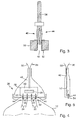
- the plug element 40 has contact elements in the form of contact pins which are provided by press-fit pins 44 are formed. Based on FIG. 3 the principle use of press-fit pins 44 will be explained in more detail.
- Press-fit pins 44 are usually made of a preferably resilient, metallic (eg tin-plated) core 46 which is pressed into a bore 48 of a board 50 axially to a longitudinal axis of the core 46.
- the bore 48 has a metallic lining 52, wherein, for example, copper sheet can be arranged on the inner circumference of the bore 48.
- the metallic lining 52 is contacted via printed conductors of the board 50 (not shown). The in FIG.
- the core 46 is exemplary and can be configured in any other way.
- the core 46 must be configured such that a hard-to-release connection to the circuit board 50 can be made.
- the overall height of the printed circuit board 50 with the contact pin attached thereto, in particular in the region of the contacting with the printed circuit board 50, is particularly small.
- a contact pin 54 is formed on which an electrical signal applied to the metallic liner 52 can be tapped.
- an electrical signal applied to the contact pin 54 can be transmitted via the lining 52 on conductor tracks of the board 50 to this signal by the control unit 26th to process accordingly.
- FIG. 4 shows an embodiment of the plug connection 38 in a cutaway side view.
- FIG. 5 shows the male member 40 of the male connector 38 from FIG. 4 in a longitudinal section through the plug connection 38 FIG. 4 ,
- the electrical supply line 32 and the signal line 36 are guided in the plug element 40 and are thus connected to the circuit board 50 to printed conductors, not shown.
- the plug element 40 has all the required components if it is possible to dispense with an additional external control device for operating the light module 18 or the illumination device 10.
- the plug element 40 comprises the microcontroller 28.
- the board 50 is angled in cross-section, so that an L-shape results (see FIG. 5 ).
- the short leg of the L-shaped board 50 has holes 48 for pressing in the press-fit pins 44.
- the holes 48 have the metallic liners 52, in which the press-fit pins 44 are pressed with the end 46 provided for this purpose.
- the circuit board 50 can be arranged in the housing of the plug element 40 such that the contact pins 54 of the press-fit pins 44 protrude out of the housing of the plug element 40 and form a matrix-like plug connector.
- FIG. 4 shows an exemplary arrangement of four pins 54 in a row next to each other. Of course, the pins 54 may also be arranged in several rows. The number and Arrangement of the contact pins 54 is arbitrary.
- the housing of the male member 40 is completed to the front through the board 50.
- the housing could be formed in two parts, wherein a front part of the housing is formed by a front part of the board 50 which carries the contact pins 54.
- the rear part of the board 50 which, for example, carries the microcontroller 28 and other electrical components of the control unit 26, can be enclosed by the housing of the plug element 40 as before.
- the housing In the front region, the housing has an opening which is designed to receive and hold the front part of the circuit board 50. This has the advantage that the plug element 40 can be mounted particularly easily, in particular if the contact pins 54 are arranged not only in a row next to each other but in several rows.
- control unit 26 generates from the signals of the lines 32 and 36, on the one hand, energy signals for controlling the light intensity of the light source 22, which are applied to the first control line 24.
- the controller 26 generates drive signals to the actuators 20 which are applied to the second control line 30.
- the plug element 40 is received by the connection element 42.
- the connection element 42 is arranged on the housing 12 of the illumination device 10 and has sockets 56 which are formed in shape and arrangement substantially complementary to the contact pins 54.
- the contact pins 54 are received in the sockets 56 and electrically contacted.
- the arrangement of the sockets forms a female connector, which cooperates electrically and mechanically with the pin strip of the contact pins 54.
- the plug element 40 is thus not only contacted by the frictional forces acting between the contact pins 54 and the sockets 56, but also mechanically held.
Landscapes
- Engineering & Computer Science (AREA)
- General Engineering & Computer Science (AREA)
- Mechanical Engineering (AREA)
- Arrangement Of Elements, Cooling, Sealing, Or The Like Of Lighting Devices (AREA)
- Non-Portable Lighting Devices Or Systems Thereof (AREA)
- Lighting Device Outwards From Vehicle And Optical Signal (AREA)
Applications Claiming Priority (1)
| Application Number | Priority Date | Filing Date | Title |
|---|---|---|---|
| DE102014202910.4A DE102014202910A1 (de) | 2014-02-18 | 2014-02-18 | Beleuchtungseinrichtung eines Kraftfahrzeugs |
Publications (3)
| Publication Number | Publication Date |
|---|---|
| EP2907697A2 true EP2907697A2 (fr) | 2015-08-19 |
| EP2907697A3 EP2907697A3 (fr) | 2015-11-11 |
| EP2907697B1 EP2907697B1 (fr) | 2020-04-08 |
Family
ID=52464226
Family Applications (1)
| Application Number | Title | Priority Date | Filing Date |
|---|---|---|---|
| EP15154065.5A Active EP2907697B1 (fr) | 2014-02-18 | 2015-02-06 | Dispositif d'éclairage d'un véhicule automobile |
Country Status (2)
| Country | Link |
|---|---|
| EP (1) | EP2907697B1 (fr) |
| DE (1) | DE102014202910A1 (fr) |
Cited By (4)
| Publication number | Priority date | Publication date | Assignee | Title |
|---|---|---|---|---|
| FR3049520A1 (fr) * | 2016-03-29 | 2017-10-06 | Valeo Vision | Dispositif d'eclairage et/ou de signalisation pour vehicule automobile automobile muni de moyens de fixation par aimant |
| EP3578429A1 (fr) * | 2018-06-06 | 2019-12-11 | Sensata Technologies, Inc. | Connecteur pour frein électromécanique |
| FR3127551A1 (fr) * | 2021-09-30 | 2023-03-31 | Valeo Vision | Module d'eclairage pour un phare de vehicule d'un vehicule automobile |
| EP4678472A1 (fr) * | 2024-07-09 | 2026-01-14 | ZKW Group GmbH | Feu de véhicule |
Families Citing this family (1)
| Publication number | Priority date | Publication date | Assignee | Title |
|---|---|---|---|---|
| DE102025000381B3 (de) | 2025-01-31 | 2026-01-08 | Mercedes-Benz Group AG | Zweiteilige Beleuchtungsvorrichtung für ein Kraftfahrzeug |
Family Cites Families (7)
| Publication number | Priority date | Publication date | Assignee | Title |
|---|---|---|---|---|
| US5728600A (en) * | 1994-11-15 | 1998-03-17 | Vlt Corporation | Circuit encapsulation process |
| DE19801061A1 (de) * | 1998-01-14 | 1999-07-15 | Hella Kg Hueck & Co | Dichtes Abdecksystem eines Gehäuses einer Beleuchtungseinrichtung für Fahrzeuge, insbesondere eines Scheinwerfers für Fahrzeuge |
| DE10163378A1 (de) * | 2001-12-21 | 2003-07-10 | Hella Kg Hueck & Co | Scheinwerfer für Fahrzeuge |
| FR2855592B1 (fr) * | 2003-05-26 | 2006-08-11 | Valeo Vision | Boitier d'electronique et projecteur de vehicule automobile a circuit electronique |
| DE102007021740A1 (de) * | 2007-05-09 | 2008-11-13 | Continental Automotive Gmbh | Leiterplatte mit integriertem Pressfit-Pin |
| DE102010040558A1 (de) * | 2010-09-10 | 2012-03-15 | Robert Bosch Gmbh | Steuergerät und Verfahren zum Entwerfen einer Leiterplatte eines Steuergeräts |
| JP5845050B2 (ja) * | 2011-10-17 | 2016-01-20 | スタンレー電気株式会社 | 車両用灯具 |
-
2014
- 2014-02-18 DE DE102014202910.4A patent/DE102014202910A1/de not_active Ceased
-
2015
- 2015-02-06 EP EP15154065.5A patent/EP2907697B1/fr active Active
Non-Patent Citations (1)
| Title |
|---|
| None |
Cited By (6)
| Publication number | Priority date | Publication date | Assignee | Title |
|---|---|---|---|---|
| FR3049520A1 (fr) * | 2016-03-29 | 2017-10-06 | Valeo Vision | Dispositif d'eclairage et/ou de signalisation pour vehicule automobile automobile muni de moyens de fixation par aimant |
| EP3578429A1 (fr) * | 2018-06-06 | 2019-12-11 | Sensata Technologies, Inc. | Connecteur pour frein électromécanique |
| US10744981B2 (en) | 2018-06-06 | 2020-08-18 | Sensata Technologies, Inc. | Electromechanical braking connector |
| FR3127551A1 (fr) * | 2021-09-30 | 2023-03-31 | Valeo Vision | Module d'eclairage pour un phare de vehicule d'un vehicule automobile |
| EP4159539A1 (fr) * | 2021-09-30 | 2023-04-05 | Valeo Vision | Module d'éclairage pour un feu de véhicule automobile |
| EP4678472A1 (fr) * | 2024-07-09 | 2026-01-14 | ZKW Group GmbH | Feu de véhicule |
Also Published As
| Publication number | Publication date |
|---|---|
| DE102014202910A1 (de) | 2015-08-20 |
| EP2907697B1 (fr) | 2020-04-08 |
| EP2907697A3 (fr) | 2015-11-11 |
Similar Documents
| Publication | Publication Date | Title |
|---|---|---|
| EP1828671B1 (fr) | Dispositif d'eclairage dote d'au moins une diode electroluminescente et phare de vehicule | |
| DE102007021865B4 (de) | Beleuchtungseinrichtung für ein Fahrzeug | |
| DE10258624B3 (de) | Scheinwerfereinheit für ein Kraftfahrzeug | |
| EP2907697B1 (fr) | Dispositif d'éclairage d'un véhicule automobile | |
| DE102009022723A1 (de) | Von rückwärts anzubringendes Leuchtdioden-Modul für Kombinationsrücklichter an Kraftfahrzeugen | |
| DE102009022724A1 (de) | Von der Seite anzubringendes Leuchtdioden-Modul für Kombinationsrücklichter an Kraftfahrzeugen | |
| DE102011081077A1 (de) | Kraftfahrzeugbeleuchtungseinrichtung | |
| DE102009022726A1 (de) | Von der Rückseite anzubringendes Leuchtdioden-Modul für Kombinationsrücklichter an Kraftfahrzeugen | |
| DE102010056313A1 (de) | Beleuchtungseinrichtung eines Kraftfahrzeugs | |
| EP2323463A2 (fr) | Appareil de commande destiné à la commande d'un dispositif d'éclairage d'un véhicule automobile et dispositif d'éclairage pour un véhicule automobile doté d'un tel dispositif de commande | |
| DE102009018447A1 (de) | Leiterplatte | |
| DE102013200925A1 (de) | Lichtquellenbaueinheit für KFZ-Scheinwerfer | |
| EP2339231B1 (fr) | Module d'éclairage pour un dispositif d'éclairage d'un véhicule automobile et dispositif d'éclairage d'un véhicule automobile doté d'un tel module d'éclairage | |
| DE102011083025A1 (de) | Beleuchtungseinrichtung für ein Fahrzeug | |
| DE202017001946U1 (de) | Scheinwerfer mit einem optischen System mit statischem Matrix-Abbiegelicht | |
| WO2019158282A1 (fr) | Module d'éclairage, dispositif, ensemble, procédé, phare et véhicule | |
| DE102009023645A1 (de) | LED-Modul | |
| EP2651695A1 (fr) | Dispositif d'éclairage intérieur dans un véhicule automobile | |
| DE102017214659A1 (de) | Leuchtmodul, beleuchtungssystem; set von leuchtmodulen und scheinwerfer | |
| EP3466756B1 (fr) | Conduit de lumière en cascade pouvant être animé | |
| DE102011084890A1 (de) | Lichtmodul einer Beleuchtungseinrichtung eines Kraftfahrzeugs | |
| DE102014221815A1 (de) | Leuchtvorrichtung und Scheinwerfer für ein Kraftfahrzeug | |
| EP2722579A1 (fr) | Phare de véhicule automobile avec source de lumière et dispositif de refroidissement pour la source de lumière | |
| EP2928022A1 (fr) | Élément de connecteur à fiches destiné à être monté sur une carte à circuit imprimé, circuit à semi-conducteur doté d'une telle carte et appareil de commande de véhicule automobile doté d'un tel circuit à semi-conducteur | |
| DE102009018448A1 (de) | Beleuchtungseinrichtung eines Kraftfahrzeugs |
Legal Events
| Date | Code | Title | Description |
|---|---|---|---|
| PUAI | Public reference made under article 153(3) epc to a published international application that has entered the european phase |
Free format text: ORIGINAL CODE: 0009012 |
|
| AK | Designated contracting states |
Kind code of ref document: A2 Designated state(s): AL AT BE BG CH CY CZ DE DK EE ES FI FR GB GR HR HU IE IS IT LI LT LU LV MC MK MT NL NO PL PT RO RS SE SI SK SM TR |
|
| AX | Request for extension of the european patent |
Extension state: BA ME |
|
| PUAL | Search report despatched |
Free format text: ORIGINAL CODE: 0009013 |
|
| AK | Designated contracting states |
Kind code of ref document: A3 Designated state(s): AL AT BE BG CH CY CZ DE DK EE ES FI FR GB GR HR HU IE IS IT LI LT LU LV MC MK MT NL NO PL PT RO RS SE SI SK SM TR |
|
| AX | Request for extension of the european patent |
Extension state: BA ME |
|
| RIC1 | Information provided on ipc code assigned before grant |
Ipc: F21V 23/06 20060101ALI20151005BHEP Ipc: F21S 8/10 20060101ALI20151005BHEP Ipc: B60Q 1/00 20060101AFI20151005BHEP |
|
| 17P | Request for examination filed |
Effective date: 20160419 |
|
| RBV | Designated contracting states (corrected) |
Designated state(s): AL AT BE BG CH CY CZ DE DK EE ES FI FR GB GR HR HU IE IS IT LI LT LU LV MC MK MT NL NO PL PT RO RS SE SI SK SM TR |
|
| STAA | Information on the status of an ep patent application or granted ep patent |
Free format text: STATUS: EXAMINATION IS IN PROGRESS |
|
| 17Q | First examination report despatched |
Effective date: 20180918 |
|
| GRAP | Despatch of communication of intention to grant a patent |
Free format text: ORIGINAL CODE: EPIDOSNIGR1 |
|
| STAA | Information on the status of an ep patent application or granted ep patent |
Free format text: STATUS: GRANT OF PATENT IS INTENDED |
|
| RIC1 | Information provided on ipc code assigned before grant |
Ipc: H01R 13/66 20060101ALN20190919BHEP Ipc: B60Q 1/00 20060101AFI20190919BHEP Ipc: F21S 45/00 20180101ALI20190919BHEP Ipc: F21S 41/19 20180101ALI20190919BHEP Ipc: H01R 12/58 20110101ALN20190919BHEP |
|
| INTG | Intention to grant announced |
Effective date: 20191023 |
|
| GRAS | Grant fee paid |
Free format text: ORIGINAL CODE: EPIDOSNIGR3 |
|
| GRAA | (expected) grant |
Free format text: ORIGINAL CODE: 0009210 |
|
| STAA | Information on the status of an ep patent application or granted ep patent |
Free format text: STATUS: THE PATENT HAS BEEN GRANTED |
|
| AK | Designated contracting states |
Kind code of ref document: B1 Designated state(s): AL AT BE BG CH CY CZ DE DK EE ES FI FR GB GR HR HU IE IS IT LI LT LU LV MC MK MT NL NO PL PT RO RS SE SI SK SM TR |
|
| REG | Reference to a national code |
Ref country code: AT Ref legal event code: REF Ref document number: 1253944 Country of ref document: AT Kind code of ref document: T Effective date: 20200415 Ref country code: CH Ref legal event code: EP |
|
| REG | Reference to a national code |
Ref country code: IE Ref legal event code: FG4D Free format text: LANGUAGE OF EP DOCUMENT: GERMAN |
|
| REG | Reference to a national code |
Ref country code: DE Ref legal event code: R096 Ref document number: 502015012193 Country of ref document: DE |
|
| REG | Reference to a national code |
Ref country code: NL Ref legal event code: MP Effective date: 20200408 |
|
| REG | Reference to a national code |
Ref country code: LT Ref legal event code: MG4D |
|
| PG25 | Lapsed in a contracting state [announced via postgrant information from national office to epo] |
Ref country code: NO Free format text: LAPSE BECAUSE OF FAILURE TO SUBMIT A TRANSLATION OF THE DESCRIPTION OR TO PAY THE FEE WITHIN THE PRESCRIBED TIME-LIMIT Effective date: 20200708 Ref country code: SE Free format text: LAPSE BECAUSE OF FAILURE TO SUBMIT A TRANSLATION OF THE DESCRIPTION OR TO PAY THE FEE WITHIN THE PRESCRIBED TIME-LIMIT Effective date: 20200408 Ref country code: IS Free format text: LAPSE BECAUSE OF FAILURE TO SUBMIT A TRANSLATION OF THE DESCRIPTION OR TO PAY THE FEE WITHIN THE PRESCRIBED TIME-LIMIT Effective date: 20200808 Ref country code: FI Free format text: LAPSE BECAUSE OF FAILURE TO SUBMIT A TRANSLATION OF THE DESCRIPTION OR TO PAY THE FEE WITHIN THE PRESCRIBED TIME-LIMIT Effective date: 20200408 Ref country code: LT Free format text: LAPSE BECAUSE OF FAILURE TO SUBMIT A TRANSLATION OF THE DESCRIPTION OR TO PAY THE FEE WITHIN THE PRESCRIBED TIME-LIMIT Effective date: 20200408 Ref country code: PT Free format text: LAPSE BECAUSE OF FAILURE TO SUBMIT A TRANSLATION OF THE DESCRIPTION OR TO PAY THE FEE WITHIN THE PRESCRIBED TIME-LIMIT Effective date: 20200817 Ref country code: GR Free format text: LAPSE BECAUSE OF FAILURE TO SUBMIT A TRANSLATION OF THE DESCRIPTION OR TO PAY THE FEE WITHIN THE PRESCRIBED TIME-LIMIT Effective date: 20200709 Ref country code: NL Free format text: LAPSE BECAUSE OF FAILURE TO SUBMIT A TRANSLATION OF THE DESCRIPTION OR TO PAY THE FEE WITHIN THE PRESCRIBED TIME-LIMIT Effective date: 20200408 |
|
| PG25 | Lapsed in a contracting state [announced via postgrant information from national office to epo] |
Ref country code: LV Free format text: LAPSE BECAUSE OF FAILURE TO SUBMIT A TRANSLATION OF THE DESCRIPTION OR TO PAY THE FEE WITHIN THE PRESCRIBED TIME-LIMIT Effective date: 20200408 Ref country code: RS Free format text: LAPSE BECAUSE OF FAILURE TO SUBMIT A TRANSLATION OF THE DESCRIPTION OR TO PAY THE FEE WITHIN THE PRESCRIBED TIME-LIMIT Effective date: 20200408 Ref country code: BG Free format text: LAPSE BECAUSE OF FAILURE TO SUBMIT A TRANSLATION OF THE DESCRIPTION OR TO PAY THE FEE WITHIN THE PRESCRIBED TIME-LIMIT Effective date: 20200708 Ref country code: HR Free format text: LAPSE BECAUSE OF FAILURE TO SUBMIT A TRANSLATION OF THE DESCRIPTION OR TO PAY THE FEE WITHIN THE PRESCRIBED TIME-LIMIT Effective date: 20200408 |
|
| PG25 | Lapsed in a contracting state [announced via postgrant information from national office to epo] |
Ref country code: AL Free format text: LAPSE BECAUSE OF FAILURE TO SUBMIT A TRANSLATION OF THE DESCRIPTION OR TO PAY THE FEE WITHIN THE PRESCRIBED TIME-LIMIT Effective date: 20200408 |
|
| REG | Reference to a national code |
Ref country code: DE Ref legal event code: R097 Ref document number: 502015012193 Country of ref document: DE |
|
| PG25 | Lapsed in a contracting state [announced via postgrant information from national office to epo] |
Ref country code: DK Free format text: LAPSE BECAUSE OF FAILURE TO SUBMIT A TRANSLATION OF THE DESCRIPTION OR TO PAY THE FEE WITHIN THE PRESCRIBED TIME-LIMIT Effective date: 20200408 Ref country code: ES Free format text: LAPSE BECAUSE OF FAILURE TO SUBMIT A TRANSLATION OF THE DESCRIPTION OR TO PAY THE FEE WITHIN THE PRESCRIBED TIME-LIMIT Effective date: 20200408 Ref country code: RO Free format text: LAPSE BECAUSE OF FAILURE TO SUBMIT A TRANSLATION OF THE DESCRIPTION OR TO PAY THE FEE WITHIN THE PRESCRIBED TIME-LIMIT Effective date: 20200408 Ref country code: CZ Free format text: LAPSE BECAUSE OF FAILURE TO SUBMIT A TRANSLATION OF THE DESCRIPTION OR TO PAY THE FEE WITHIN THE PRESCRIBED TIME-LIMIT Effective date: 20200408 Ref country code: IT Free format text: LAPSE BECAUSE OF FAILURE TO SUBMIT A TRANSLATION OF THE DESCRIPTION OR TO PAY THE FEE WITHIN THE PRESCRIBED TIME-LIMIT Effective date: 20200408 Ref country code: EE Free format text: LAPSE BECAUSE OF FAILURE TO SUBMIT A TRANSLATION OF THE DESCRIPTION OR TO PAY THE FEE WITHIN THE PRESCRIBED TIME-LIMIT Effective date: 20200408 Ref country code: SM Free format text: LAPSE BECAUSE OF FAILURE TO SUBMIT A TRANSLATION OF THE DESCRIPTION OR TO PAY THE FEE WITHIN THE PRESCRIBED TIME-LIMIT Effective date: 20200408 |
|
| PLBE | No opposition filed within time limit |
Free format text: ORIGINAL CODE: 0009261 |
|
| STAA | Information on the status of an ep patent application or granted ep patent |
Free format text: STATUS: NO OPPOSITION FILED WITHIN TIME LIMIT |
|
| PG25 | Lapsed in a contracting state [announced via postgrant information from national office to epo] |
Ref country code: SK Free format text: LAPSE BECAUSE OF FAILURE TO SUBMIT A TRANSLATION OF THE DESCRIPTION OR TO PAY THE FEE WITHIN THE PRESCRIBED TIME-LIMIT Effective date: 20200408 Ref country code: PL Free format text: LAPSE BECAUSE OF FAILURE TO SUBMIT A TRANSLATION OF THE DESCRIPTION OR TO PAY THE FEE WITHIN THE PRESCRIBED TIME-LIMIT Effective date: 20200408 |
|
| 26N | No opposition filed |
Effective date: 20210112 |
|
| PG25 | Lapsed in a contracting state [announced via postgrant information from national office to epo] |
Ref country code: SI Free format text: LAPSE BECAUSE OF FAILURE TO SUBMIT A TRANSLATION OF THE DESCRIPTION OR TO PAY THE FEE WITHIN THE PRESCRIBED TIME-LIMIT Effective date: 20200408 |
|
| PG25 | Lapsed in a contracting state [announced via postgrant information from national office to epo] |
Ref country code: MC Free format text: LAPSE BECAUSE OF FAILURE TO SUBMIT A TRANSLATION OF THE DESCRIPTION OR TO PAY THE FEE WITHIN THE PRESCRIBED TIME-LIMIT Effective date: 20200408 |
|
| GBPC | Gb: european patent ceased through non-payment of renewal fee |
Effective date: 20210206 |
|
| REG | Reference to a national code |
Ref country code: BE Ref legal event code: MM Effective date: 20210228 |
|
| PG25 | Lapsed in a contracting state [announced via postgrant information from national office to epo] |
Ref country code: LU Free format text: LAPSE BECAUSE OF NON-PAYMENT OF DUE FEES Effective date: 20210206 Ref country code: LI Free format text: LAPSE BECAUSE OF NON-PAYMENT OF DUE FEES Effective date: 20210228 Ref country code: CH Free format text: LAPSE BECAUSE OF NON-PAYMENT OF DUE FEES Effective date: 20210228 |
|
| PG25 | Lapsed in a contracting state [announced via postgrant information from national office to epo] |
Ref country code: IE Free format text: LAPSE BECAUSE OF NON-PAYMENT OF DUE FEES Effective date: 20210206 Ref country code: GB Free format text: LAPSE BECAUSE OF NON-PAYMENT OF DUE FEES Effective date: 20210206 Ref country code: FR Free format text: LAPSE BECAUSE OF NON-PAYMENT OF DUE FEES Effective date: 20210228 |
|
| REG | Reference to a national code |
Ref country code: AT Ref legal event code: MM01 Ref document number: 1253944 Country of ref document: AT Kind code of ref document: T Effective date: 20210206 |
|
| PG25 | Lapsed in a contracting state [announced via postgrant information from national office to epo] |
Ref country code: AT Free format text: LAPSE BECAUSE OF NON-PAYMENT OF DUE FEES Effective date: 20210206 |
|
| REG | Reference to a national code |
Ref country code: DE Ref legal event code: R083 Ref document number: 502015012193 Country of ref document: DE |
|
| PG25 | Lapsed in a contracting state [announced via postgrant information from national office to epo] |
Ref country code: BE Free format text: LAPSE BECAUSE OF NON-PAYMENT OF DUE FEES Effective date: 20210228 |
|
| PG25 | Lapsed in a contracting state [announced via postgrant information from national office to epo] |
Ref country code: HU Free format text: LAPSE BECAUSE OF FAILURE TO SUBMIT A TRANSLATION OF THE DESCRIPTION OR TO PAY THE FEE WITHIN THE PRESCRIBED TIME-LIMIT; INVALID AB INITIO Effective date: 20150206 |
|
| PG25 | Lapsed in a contracting state [announced via postgrant information from national office to epo] |
Ref country code: CY Free format text: LAPSE BECAUSE OF FAILURE TO SUBMIT A TRANSLATION OF THE DESCRIPTION OR TO PAY THE FEE WITHIN THE PRESCRIBED TIME-LIMIT Effective date: 20200408 |
|
| PG25 | Lapsed in a contracting state [announced via postgrant information from national office to epo] |
Ref country code: MK Free format text: LAPSE BECAUSE OF FAILURE TO SUBMIT A TRANSLATION OF THE DESCRIPTION OR TO PAY THE FEE WITHIN THE PRESCRIBED TIME-LIMIT Effective date: 20200408 |
|
| PG25 | Lapsed in a contracting state [announced via postgrant information from national office to epo] |
Ref country code: MT Free format text: LAPSE BECAUSE OF FAILURE TO SUBMIT A TRANSLATION OF THE DESCRIPTION OR TO PAY THE FEE WITHIN THE PRESCRIBED TIME-LIMIT Effective date: 20200408 |
|
| PG25 | Lapsed in a contracting state [announced via postgrant information from national office to epo] |
Ref country code: TR Free format text: LAPSE BECAUSE OF FAILURE TO SUBMIT A TRANSLATION OF THE DESCRIPTION OR TO PAY THE FEE WITHIN THE PRESCRIBED TIME-LIMIT Effective date: 20200408 |
|
| REG | Reference to a national code |
Ref country code: DE Ref legal event code: R081 Ref document number: 502015012193 Country of ref document: DE Owner name: MARELLI GERMANY GMBH, DE Free format text: FORMER OWNER: AUTOMOTIVE LIGHTING REUTLINGEN GMBH, 72762 REUTLINGEN, DE |
|
| PGFP | Annual fee paid to national office [announced via postgrant information from national office to epo] |
Ref country code: DE Payment date: 20260121 Year of fee payment: 12 |