EP2907865A1 - Réduction des dépôts et des réactions secondaires dans une conversion thermique - Google Patents
Réduction des dépôts et des réactions secondaires dans une conversion thermique Download PDFInfo
- Publication number
- EP2907865A1 EP2907865A1 EP15157199.9A EP15157199A EP2907865A1 EP 2907865 A1 EP2907865 A1 EP 2907865A1 EP 15157199 A EP15157199 A EP 15157199A EP 2907865 A1 EP2907865 A1 EP 2907865A1
- Authority
- EP
- European Patent Office
- Prior art keywords
- pipeline
- reamer
- stream
- vapor
- rod
- Prior art date
- Legal status (The legal status is an assumption and is not a legal conclusion. Google has not performed a legal analysis and makes no representation as to the accuracy of the status listed.)
- Granted
Links
- 238000006243 chemical reaction Methods 0.000 title claims abstract description 32
- 238000010517 secondary reaction Methods 0.000 title description 4
- 230000000116 mitigating effect Effects 0.000 title description 2
- 238000000197 pyrolysis Methods 0.000 claims abstract description 47
- 239000007788 liquid Substances 0.000 claims abstract description 22
- 238000010791 quenching Methods 0.000 claims abstract description 7
- 230000000171 quenching effect Effects 0.000 claims abstract description 6
- 230000009849 deactivation Effects 0.000 claims 1
- 238000000034 method Methods 0.000 description 64
- 230000008569 process Effects 0.000 description 39
- 239000000463 material Substances 0.000 description 21
- 239000002028 Biomass Substances 0.000 description 20
- 239000000047 product Substances 0.000 description 19
- 239000007789 gas Substances 0.000 description 13
- 230000008021 deposition Effects 0.000 description 8
- 239000007787 solid Substances 0.000 description 7
- VNWKTOKETHGBQD-UHFFFAOYSA-N methane Chemical compound C VNWKTOKETHGBQD-UHFFFAOYSA-N 0.000 description 6
- 239000012263 liquid product Substances 0.000 description 5
- 238000009987 spinning Methods 0.000 description 5
- 239000002023 wood Substances 0.000 description 5
- 239000012075 bio-oil Substances 0.000 description 4
- 239000002803 fossil fuel Substances 0.000 description 4
- 239000012808 vapor phase Substances 0.000 description 4
- 230000009471 action Effects 0.000 description 3
- 239000006227 byproduct Substances 0.000 description 3
- 238000002485 combustion reaction Methods 0.000 description 3
- 238000009833 condensation Methods 0.000 description 3
- 230000005494 condensation Effects 0.000 description 3
- 238000012856 packing Methods 0.000 description 3
- 238000012545 processing Methods 0.000 description 3
- IJGRMHOSHXDMSA-UHFFFAOYSA-N Atomic nitrogen Chemical compound N#N IJGRMHOSHXDMSA-UHFFFAOYSA-N 0.000 description 2
- CURLTUGMZLYLDI-UHFFFAOYSA-N Carbon dioxide Chemical compound O=C=O CURLTUGMZLYLDI-UHFFFAOYSA-N 0.000 description 2
- 230000004075 alteration Effects 0.000 description 2
- 230000015556 catabolic process Effects 0.000 description 2
- 239000000470 constituent Substances 0.000 description 2
- 238000006731 degradation reaction Methods 0.000 description 2
- 239000000446 fuel Substances 0.000 description 2
- 238000002309 gasification Methods 0.000 description 2
- 238000004519 manufacturing process Methods 0.000 description 2
- 238000012986 modification Methods 0.000 description 2
- 230000004048 modification Effects 0.000 description 2
- 239000003345 natural gas Substances 0.000 description 2
- 239000003208 petroleum Substances 0.000 description 2
- 238000012546 transfer Methods 0.000 description 2
- 238000007740 vapor deposition Methods 0.000 description 2
- OKTJSMMVPCPJKN-UHFFFAOYSA-N Carbon Chemical compound [C] OKTJSMMVPCPJKN-UHFFFAOYSA-N 0.000 description 1
- UGFAIRIUMAVXCW-UHFFFAOYSA-N Carbon monoxide Chemical compound [O+]#[C-] UGFAIRIUMAVXCW-UHFFFAOYSA-N 0.000 description 1
- 244000276464 Melochia pyramidata Species 0.000 description 1
- 150000001336 alkenes Chemical class 0.000 description 1
- 229910045601 alloy Inorganic materials 0.000 description 1
- 239000000956 alloy Substances 0.000 description 1
- 239000010426 asphalt Substances 0.000 description 1
- 229910052799 carbon Inorganic materials 0.000 description 1
- 229910002092 carbon dioxide Inorganic materials 0.000 description 1
- 239000001569 carbon dioxide Substances 0.000 description 1
- 229910002091 carbon monoxide Inorganic materials 0.000 description 1
- 239000003575 carbonaceous material Substances 0.000 description 1
- 239000000969 carrier Substances 0.000 description 1
- 239000003610 charcoal Substances 0.000 description 1
- 239000003245 coal Substances 0.000 description 1
- 235000013353 coffee beverage Nutrition 0.000 description 1
- 239000000567 combustion gas Substances 0.000 description 1
- 238000001816 cooling Methods 0.000 description 1
- 238000005336 cracking Methods 0.000 description 1
- 230000001186 cumulative effect Effects 0.000 description 1
- 238000005520 cutting process Methods 0.000 description 1
- 238000011161 development Methods 0.000 description 1
- 238000010586 diagram Methods 0.000 description 1
- 238000009826 distribution Methods 0.000 description 1
- 238000011143 downstream manufacturing Methods 0.000 description 1
- -1 e.g. Substances 0.000 description 1
- 235000015114 espresso Nutrition 0.000 description 1
- 230000004907 flux Effects 0.000 description 1
- 239000012634 fragment Substances 0.000 description 1
- 239000002737 fuel gas Substances 0.000 description 1
- 239000000295 fuel oil Substances 0.000 description 1
- 239000010439 graphite Substances 0.000 description 1
- 229910002804 graphite Inorganic materials 0.000 description 1
- 230000005484 gravity Effects 0.000 description 1
- 238000010438 heat treatment Methods 0.000 description 1
- 239000001257 hydrogen Substances 0.000 description 1
- 229910052739 hydrogen Inorganic materials 0.000 description 1
- 125000004435 hydrogen atom Chemical class [H]* 0.000 description 1
- 238000002347 injection Methods 0.000 description 1
- 239000007924 injection Substances 0.000 description 1
- 238000003780 insertion Methods 0.000 description 1
- 230000037431 insertion Effects 0.000 description 1
- 239000000203 mixture Substances 0.000 description 1
- 229910052757 nitrogen Inorganic materials 0.000 description 1
- 239000011368 organic material Substances 0.000 description 1
- 239000003209 petroleum derivative Substances 0.000 description 1
- 239000012071 phase Substances 0.000 description 1
- 238000006116 polymerization reaction Methods 0.000 description 1
- 230000035484 reaction time Effects 0.000 description 1
- 238000011084 recovery Methods 0.000 description 1
- 230000009467 reduction Effects 0.000 description 1
- 238000007670 refining Methods 0.000 description 1
- 239000004576 sand Substances 0.000 description 1
- 238000007789 sealing Methods 0.000 description 1
- 239000011343 solid material Substances 0.000 description 1
- 229910001220 stainless steel Inorganic materials 0.000 description 1
- 239000010935 stainless steel Substances 0.000 description 1
- 229910001256 stainless steel alloy Inorganic materials 0.000 description 1
- 239000000126 substance Substances 0.000 description 1
- 238000004227 thermal cracking Methods 0.000 description 1
- UONOETXJSWQNOL-UHFFFAOYSA-N tungsten carbide Chemical compound [W+]#[C-] UONOETXJSWQNOL-UHFFFAOYSA-N 0.000 description 1
- 238000010518 undesired secondary reaction Methods 0.000 description 1
- 238000010977 unit operation Methods 0.000 description 1
- 239000011345 viscous material Substances 0.000 description 1
Images



Classifications
-
- B—PERFORMING OPERATIONS; TRANSPORTING
- B08—CLEANING
- B08B—CLEANING IN GENERAL; PREVENTION OF FOULING IN GENERAL
- B08B9/00—Cleaning hollow articles by methods or apparatus specially adapted thereto
- B08B9/02—Cleaning pipes or tubes or systems of pipes or tubes
- B08B9/027—Cleaning the internal surfaces; Removal of blockages
- B08B9/04—Cleaning the internal surfaces; Removal of blockages using cleaning devices introduced into and moved along the pipes
- B08B9/043—Cleaning the internal surfaces; Removal of blockages using cleaning devices introduced into and moved along the pipes moved by externally powered mechanical linkage, e.g. pushed or drawn through the pipes
- B08B9/0436—Cleaning the internal surfaces; Removal of blockages using cleaning devices introduced into and moved along the pipes moved by externally powered mechanical linkage, e.g. pushed or drawn through the pipes provided with mechanical cleaning tools, e.g. scrapers, with or without additional fluid jets
-
- B—PERFORMING OPERATIONS; TRANSPORTING
- B08—CLEANING
- B08B—CLEANING IN GENERAL; PREVENTION OF FOULING IN GENERAL
- B08B9/00—Cleaning hollow articles by methods or apparatus specially adapted thereto
-
- B—PERFORMING OPERATIONS; TRANSPORTING
- B08—CLEANING
- B08B—CLEANING IN GENERAL; PREVENTION OF FOULING IN GENERAL
- B08B9/00—Cleaning hollow articles by methods or apparatus specially adapted thereto
- B08B9/02—Cleaning pipes or tubes or systems of pipes or tubes
- B08B9/027—Cleaning the internal surfaces; Removal of blockages
- B08B9/04—Cleaning the internal surfaces; Removal of blockages using cleaning devices introduced into and moved along the pipes
- B08B9/043—Cleaning the internal surfaces; Removal of blockages using cleaning devices introduced into and moved along the pipes moved by externally powered mechanical linkage, e.g. pushed or drawn through the pipes
- B08B9/045—Cleaning the internal surfaces; Removal of blockages using cleaning devices introduced into and moved along the pipes moved by externally powered mechanical linkage, e.g. pushed or drawn through the pipes the cleaning devices being rotated while moved, e.g. flexible rotating shaft or "snake"
-
- F—MECHANICAL ENGINEERING; LIGHTING; HEATING; WEAPONS; BLASTING
- F23—COMBUSTION APPARATUS; COMBUSTION PROCESSES
- F23J—REMOVAL OR TREATMENT OF COMBUSTION PRODUCTS OR COMBUSTION RESIDUES; FLUES
- F23J3/00—Removing solid residues from passages or chambers beyond the fire, e.g. from flues by soot blowers
- F23J3/02—Cleaning furnace tubes; Cleaning flues or chimneys
Definitions
- the present invention is related to pyrolysis and other thermal conversion processes, and more particular to systems and method for reducing deposits and mitigating secondary reactions in pyrolysis and other thermal conversion processes.
- Solid biomass typically wood and wood residues
- useful products e.g., fuels or chemicals
- thermal conversion is combustion, where air is added and the entire biomass feed material is burned to give hot combustion gases for the production of heat and steam.
- gasification where a small portion of the biomass feedstock is combusted with air in order to convert the rest of the biomass into a combustible fuel gas.
- the combustible gas known as producer gas, behaves like natural gas but typically has between 10 and 30% of the energy content of natural gas.
- a final example of thermal conversion is pyrolysis where the solid biomass is converted to liquid and char, along with a gaseous by-product, essentially in the absence of air.
- pyrolysis or thermal cracking is the conversion of biomass, fossil fuels and other carbonaceous feedstocks to a liquid and/or char by the action of heat, normally without using direct combustion in a conversion unit.
- a small quantity of combustible gas is also a typical by-product.
- pyrolysis was a relatively slow process where the resulting liquid product was a viscous tar and "pyrolygneous" liquor.
- Conventional slow pyrolysis has typically taken place at temperatures below 400 °C and at processing times ranging from several seconds to minutes prior to the unit operations of condensing the product vapors into a liquid product. The processing times can be measured in hours for some slow pyrolysis processes used for charcoal production.
- the distribution of the three main products from slow pyrolysis of wood on a weight basis is approximately 30 - 33% liquid, 33 -35% char and 33-35% gas.
- fast pyrolysis A more modern form of pyrolysis, termed fast pyrolysis, was discovered in the late 1970"s when researchers noted that an extremely high yield of a relatively non-viscous liquid (i.e., a liquid that readily flows at room temperature) was possible from biomass. In fact, liquid yields approaching 80% of the weight of the input woody biomass material were possible if the pyrolysis temperatures were moderately raised and the conversion was allowed to take place over a very short time period, typically less than 5 seconds. In general, the two primary processing requirements to meet the conditions for fast pyrolysis are very high heat flux to the biomass with a corresponding high heating rate of the biomass material, and short conversion times followed by rapid quenching of the product vapor.
- the yields of the three main products are approximately, 70-75% liquid, 12-14% char, and 12-14% gas.
- the homogeneous liquid product from fast pyrolysis which has the appearance of espresso coffee, has since become known as bio-oil.
- Bio-oil is suitable as a fuel for clean, controlled combustion in boilers, and for use in diesel and stationary turbines. This is in stark contrast to slow pyrolysis, which produces a thick, low quality, two-phase tar-aqueous mixture in very low yields.
- the fast pyrolysis of solid biomass causes the major part of its solid organic material to be instantaneously transformed into a vapor phase.
- This vapor phase contains both non-condensable gases (including methane, hydrogen, carbon monoxide, carbon dioxide and olefins) and condensable vapors. It is the condensable vapors that, when condensed, constitute the final liquid bio-oil product, and the yield and value of this bio-oil product is a strong function of the method and efficiency of the downstream capture and recovery system.
- the condensable vapors produced during fast pyrolysis will continue to react as long as they remain at elevated temperatures in the vapor phase, and therefore must be quickly cooled or "quenched" in the downstream process.
- the vapor-phase constituents will continue to react at an appreciable rate, and thermal degradation will be evident, at temperatures above 400°C. If a fast pyrolysis process is to be commercially viable, it is therefore extremely important to instantaneously quench the vapor stream, after a suitable reaction time, to a temperature below about 400°C preferably less than 200 °C and more preferably less than 50 °C. Such a requirement to rapidly cool a hot vapor stream is not easily accomplished in scaled-up commercial fast pyrolysis systems.
- Described herein are systems and methods for reducing cumulative deposition and unwanted secondary thermal reactions in pyrolysis and other thermal conversion processes.
- a system comprises a device, referred to as a reamer, for removing product deposits between thermal conversion and condensation operations of a pyrolysis process.
- the reamer may comprise, but is not limited to, a mechanical reciprocating rod or ram, a mechanical auger, a drill bit, a high-temperature wiper, brush, or punch to remove deposits and prevent secondary reactions.
- the reamer may use a high-velocity curtain or jet (i.e., a hydraulic or pneumatic stream) of steam, product gas, recycle gas, other gas jet or non-condensing liquid to remove deposits.
- the reamer removes deposits during the pyrolysis process allowing for continuous operation of the pyrolysis process.
- the present invention is not limited to applications involving the fast pyrolysis of biomass feedstocks.
- the present invention can be used in the fast pyrolysis or rapid cracking of any carbonaceous feedstock that is subjected to fast thermal conversion, including the thermal conversion, refining, gasification, and upgrading of all biomass, petroleum and fossil fuel feedstocks.
- the present invention is not limited only to applications between the thermal conversion system and the condensing system, but includes other areas in the thermal process where a thermal gradient exists, and where products are thermally reactive and subject to unwanted deposition and secondary thermal reactions. For example, there are situations where a product gas, which is being recycled to the thermal conversion unit for various purposes, may contain some residual vapors that are subject to deposition and secondary thermal reactions. The present invention may also be applied to prevent such an occurrence.
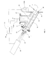
- Figure 1 shows a mechanical reamer according to an exemplary embodiment of the present invention.
- the reamer is configured to clear material build up in a pipeline 5 used for transporting a hot vapor stream to a condensing column or chamber 7 in a pyrolysis process. Details of an exemplary pyrolysis process in which the reamer can be used are given in co-pending application, Serial No. 1 1/943,329 , titled “Rapid Thermal Conversion of Biomass,” filed on November 20, 2007, the specification of which is incorporated herein by reference.
- the hot vapor stream flows through the pipeline 5 in the direction 9, and enters the condensing camber 7 where the hot vapor stream is quenched with a cool liquid to condense the hot vapor into a liquid product.
- a hot-cold interface zone forms around the interface between the pipeline 5 and the condensing camber 7. Due to the hot-cold interface zone, deposition of solid material (not shown) in the pipeline 5 occurs in the hot-cold interface zone.
- the hot vapor stream comprises vaporized biomass (e.g., wood) that deposits solid carbonaceous material in the pipeline 5 in the hot-cold interface zone. As the deposited material builds up in the pipeline 5, the flow of vapor in the pipeline 5 is impeded.
- the reamer is activated to clear the deposited material from the pipeline 5 during operation when a pressure differential across the hot-cold interface zone reaches a certain level.
- the reamer comprises a rod or shaft 10, a ram head 15 attached to one end of the rod 10, and a mechanical actuator 20 mechanically coupled to the other end of the rod 10 for moving the rod 10 and ram head 15 in a reciprocating motion between a retracted position 23 and an extended position 27.
- exemplary mechanical actuators include, but are not limited to, rack and pinion, hydraulic, or pneumatic actuators.
- the pipeline 5 includes a section 30 coupled to the inlet port 35 of the chamber 7 at an angle. The angle facilitates the removal of the deposits by allowing gravity to deliver into the proximate high-velocity product stream.
- the ram head 15 and rod 10 of the reamer move within this section 30 of the pipeline 5.
- the mechanical actuator 20 is mounted on a bracket 45 that is bolted to a closed end of this section 30 of the pipeline 5.
- Another section of the pipeline 37 coupled to the source of the vapor stream is coupled to section 30 of the pipeline 5 at approximately the midpoint.
- the ram head 15 is positioned behind the region where sections 30 and 37 of the pipeline 5 are coupled to facilitate the flow of hot vapor through the pipeline 5 when the reamer is not in use.
- the reamer includes a seal 42 around the rod 10 at the point the rod 10 enters the pipeline 5.
- the seal 42 allows the rod 10 to reciprocate while sealing the pipeline 5 from the outside to maintain a seal between the process and the atmosphere.
- the seal 42 may comprise a mechanical seal or a high temperature packing glad, e.g., that uses graphite as a packing material around the rod.
- the ram head 15 is generally cylindrical with a beveled front edge 17 to break the deposited material, which may be hard and somewhat sticky.
- Other shapes or devices may be used for the front edge besides a beveled shape. Examples include, but are not limited to, a spinning auger, cutting head, spinning wire, brush, high-temperature wiper, drill bit, etc.
- the ram head 15 is attached to the rod 10 by four spokes 32 that are welded 34 to the inner surface of the ram head 15 and the rod 10.
- the ram head 15 may be attached to the rod 10 using a different number of spokes. Between the spokes 32 are openings 36 that allow vapor to flow though the ram head 15.
- the open cross-sectional area is preferably at least 30% of the total cross-sectional area of the pipeline, and more preferably 80%. These opening 36 allow the reamer to operate while vapor flows through the pipeline 5. As a result, the reamer is able clear material from the pipeline 5 without having to stop the pyrolysis process allowing for continuous operation.
- the clearance between the ram head 15 and the inner wall of the pipeline 5 is preferably between 0.125" and 0.500" inches, and more preferably 0.250" inches.
- the clearance should be small to clear as much of the cross-sectional area of the pipeline as possible, but not so small that the ram head 15 impacts the inner wall of the pipeline 5.
- the ram head 15, spokes 32, and rod 10 are made of a robust high strength material that can withstand the hot vapor environment in the pipeline 5. Suitable materials include, but are not limited to, stainless steel alloys.
- areas of the ram head 15 subjected to wear are made of a high strength alloy and/or treated by hard surfacing. For example, a tungsten-carbide hard surface may be applied to the ram head 15.
- FIG. 1 shows a diagram of a control system 105 for the reamer according to an embodiment of the invention.
- the control system 105 is configured to activate the reamer when the deposited material in the pipeline 5 impedes the vapor flow by a certain amount.
- the control system 105 includes at least two pressure sensors 1 10a and 1 10b positioned at different ends of the hot-cold interface zone.
- the control system 105 also includes a controller 1 15, e.g., computer system, coupled to the pressures sensors 1 10a and 1 10b and the reamer.
- the controller 105 uses the pressure readings from the pressure sensors 1 10a and 1 10b to measure and monitor the differential pressure across the hot-cold interface zone during operation.
- the controller 115 activates the reamer and starts the clearing operation, in which the ram head 15 of the reamer is moved in a reciprocating motion by the mechanical actuator 20 to clear the deposited material from the pipeline 5.
- the clearing opening is performed while the vapor flows through the pipeline 5 and the openings of the ram head 15. This allows the pyrolysis process to continue during the clearing operation.
- the speed of the ram head 15 is controlled to avoid impact damage of the pipeline 5 by the ram head 15.
- Insertion rate or stroke rate be controlled, by way of example, through the use of a needle valve on the actuator assembly of the reamer. Stroke rate is adjusted to limit the disturbance to the vapor and non-condensable gas stream while minimizing the mechanical stresses to the pipe works and associated reamer assembly. The stroke rate is typically adjusted to less than 50 ft/s, more preferably to less than 10 ft/s, and more preferably to less than 1 ft/s.
- the controller 115 monitors the differential pressure during the clearing operations and stops the clearing operation when the differential pressure drops below a predetermined level indicating that the pipeline 5 is clear. When this occurs, the ram head 15 is retracted to the retracted position 23.
- the pipeline 5 may be refractory lines or insulated to avoid unwanted heat losses.
- the pipeline 5 may be heat traced to maintain the desired transfer line temperature to further minimize condensable vapor deposition.
- the pipeline temperature should be kept above 400 C, preferably above 450, and more preferably above 500 C up to the point where quenching is desired.
- the reamer according to this embodiment of the invention provides several advantages. By clearing the deposited material from the pipeline the reamer prevents blockages that can lead to system shut down. Further, the reamer clears the deposited material during operation allowing for a continuous pyrolysis process. In other words, the pyrolysis process does not need to stop for the reamer to clear the deposited material. Further, by keeping the pipeline clear during the process the reamer maintains more consistent operating conditions during the process and prevents high pressure build up in the pipeline due to blockage.
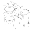
- Figure 4 shows an example of the reamer coupled to a pipeline 5 between a cyclonic separator 12 and a condensing chamber 7.
- the cyclonic separator 12 separates the hot vapor stream from heat carriers (e.g., sand) used to thermally covert the feedstock (e.g., biomass) into the hot vapor stream in a thermal conversion process.
- the condensing chamber 7 quickly quenches the incoming hot vapor stream into liquid product, which creates the hot-cold interface zone.
- the reamer advantageously removes product deposits that form in the pipeline 5 due to the hot-cold interface zone, and thereby prevents unwanted increases in system back pressure and unwanted secondary reactions.
- the reamer may be located in other areas in the thermal process where a thermal gradient exists, and where products are thermally reactive and subject to unwanted deposition and secondary thermal reactions.
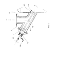
- a movable reamer having a high pressure nozzle head 1 15 uses high-velocity gaseous, vapor or liquid jet or stream to remove deposits of condensed product vapors.
- the stream is injected at a velocity of between 50 to 500 feet/second (fps) to dislodge the condensed product, e.g., from the pipeline at or near a hot-cold interface. More preferably, a velocity of 100 to 200 fps is used and most preferably, a velocity in the range of 100 to 150 fps is used.
- the movable high pressure nozzle head 1 15 is attached to the end of a rod 110, which moves the nozzle head 1 15 between the retracted position 123 and the extended position 127 during the clearing operation.
- the rod 1 10 and nozzle head 115 may be moved via a pneumatic or hydraulic system.
- a seal 142 e.g., packing glad
- a high-velocity stream is injected into the pipeline from the high pressure nozzle head 115 to dislodge deposits from the pipeline.
- the nozzle head 115 receives the high-velocity stream through a lumen in the rod 110 that is fluidly coupled to a supply line 138 (e.g., a braided flex line) outside the pipeline.
- the high pressure stream may be supplied by an air compressor, recycled gas (e.g., a inert by-product gas stream) steam, nitrogen or other gaseous or vapor stream.
- Figure 6 and 7 show a side view and a front view of the nozzle head 1 15, respectively, according to an embodiment of the invention.
- the nozzle head 1 15 comprises a plurality of injection holes 122 arranged circumferential Iy along a tapered portion 125 of the nozzle head 1 15 for injecting the high pressure stream onto the pipeline wall.
- the nozzle head 1 15 is attached to the rod 1 10 by a plurality of support members 1 17.
- the support members 1 17 have lumens fluidly coupled to the lumen 1 12 of the rod for supplying the high pressure stream to the nozzle head 1 15. Openings 136 between the support members 1 17 allow the hot vapor stream of the pyrolysis process to flow through the nozzle head 115 during the clearing operation. This advantageously allows the reamer to clear deposits from the pipeline wall without having to stop the pyrolysis process.
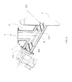
- Figure 8 shows a reamer according to another embodiment of the present invention.
- the reamer comprises a rotating auger 225 (e.g., a helical shaft) to clear deposits from the pipeline 5.
- the rod 210 extends the auger 225 from a retracted position 223 to an extended position 227 while rotating the auger 225 to remove the deposits from the pipeline.
- the auger 225 can be rotated by an electric motor, an air driven motor or other driver known in the art.
- the rod 1 10 and the auger 225 may be moved between the retracted and extended positions via a pneumatic or hydraulic system.
- the reamer may be activated when a sensed pressure differential exceeds a certain level in a manner similar to the embodiment shown in Figure 1 .
- the hot product stream is allowed to flow through the helical structure of the auger 225 for continuous operation of the pyrolysis process.
- a reamer having a wire brush head assembly 326 is used scour the wall of the pipeline to remove deposits of condensed product vapors, as shown in Figure 9 .
- the wire bush head assembly 325 may be constructed of a high temperature, flexible abrasive resistant material such as stainless steel.
- the rod 310 When the reamer is activated, the rod 310 extends the wire brush head 325 from the retracted position 323 to the extended position 327 to scour the pipeline walls.
- the movement of the rod 310 and brush head 325 in this embodiment may be via a pneumatic or hydraulic system.
- the brush head 325 can be extended and retracted with or without a spinning action.
- the brush head 325 can be rotated by an electric motor, an air driven motor or other driver known in the art.
- An interference fit may be used to fit the brush head 325 within the pipeline to provide enough contact between the brush head 325 and the pipeline wall to remove deposited materials on the pipeline wall.
- the hot product stream is allowed to flow through the brush head 325 for continuous operation of the pyrolysis process.
- the rotational speed of the auger 225 or spinning brush head 325 may be 10 to 500 rpm, preferably 50 to 250 rpm, and more preferably between 50 and 150 rpm. The more preferably range allows for adequate reduction of deposited materials while reducing the wear of the rotation equipment.
Landscapes
- Engineering & Computer Science (AREA)
- Mechanical Engineering (AREA)
- General Engineering & Computer Science (AREA)
- Processing Of Solid Wastes (AREA)
- Production Of Liquid Hydrocarbon Mixture For Refining Petroleum (AREA)
- Waste-Gas Treatment And Other Accessory Devices For Furnaces (AREA)
- Industrial Gases (AREA)
Applications Claiming Priority (2)
| Application Number | Priority Date | Filing Date | Title |
|---|---|---|---|
| US12/110,197 US8097090B2 (en) | 2008-04-25 | 2008-04-25 | Mitigation of deposits and secondary reactions in thermal conversion processes |
| EP09734673.8A EP2303990B1 (fr) | 2008-04-25 | 2009-03-06 | Procédé de pyrolyse en continu |
Related Parent Applications (2)
| Application Number | Title | Priority Date | Filing Date |
|---|---|---|---|
| EP09734673.8A Division-Into EP2303990B1 (fr) | 2008-04-25 | 2009-03-06 | Procédé de pyrolyse en continu |
| EP09734673.8A Division EP2303990B1 (fr) | 2008-04-25 | 2009-03-06 | Procédé de pyrolyse en continu |
Publications (2)
| Publication Number | Publication Date |
|---|---|
| EP2907865A1 true EP2907865A1 (fr) | 2015-08-19 |
| EP2907865B1 EP2907865B1 (fr) | 2016-09-14 |
Family
ID=41213784
Family Applications (2)
| Application Number | Title | Priority Date | Filing Date |
|---|---|---|---|
| EP09734673.8A Active EP2303990B1 (fr) | 2008-04-25 | 2009-03-06 | Procédé de pyrolyse en continu |
| EP15157199.9A Active EP2907865B1 (fr) | 2008-04-25 | 2009-03-06 | Réduction des dépôts et des réactions secondaires dans une conversion thermique |
Family Applications Before (1)
| Application Number | Title | Priority Date | Filing Date |
|---|---|---|---|
| EP09734673.8A Active EP2303990B1 (fr) | 2008-04-25 | 2009-03-06 | Procédé de pyrolyse en continu |
Country Status (11)
| Country | Link |
|---|---|
| US (2) | US8097090B2 (fr) |
| EP (2) | EP2303990B1 (fr) |
| CN (1) | CN102015133A (fr) |
| BR (1) | BRPI0910584B1 (fr) |
| CA (1) | CA2719698C (fr) |
| CO (1) | CO6310974A2 (fr) |
| DK (2) | DK2303990T3 (fr) |
| EC (1) | ECSP10010536A (fr) |
| MX (1) | MX2010011618A (fr) |
| MY (1) | MY149013A (fr) |
| WO (1) | WO2009131757A2 (fr) |
Families Citing this family (37)
| Publication number | Priority date | Publication date | Assignee | Title |
|---|---|---|---|---|
| CN101460473A (zh) | 2006-04-03 | 2009-06-17 | 药物热化学品公司 | 热提取方法和产物 |
| US8298406B2 (en) * | 2009-05-21 | 2012-10-30 | Coates Engineering, Llc | Method and apparatus for maximizing throughput of indirectly heated rotary kilns |
| CA2774881C (fr) * | 2009-09-25 | 2017-04-04 | Scutum Capital Ag | Procede et appareil pour le traitement thermique en plusieurs etapes de rebuts de caoutchouc, en particulier de pneus uses |
| US8323455B1 (en) * | 2009-10-22 | 2012-12-04 | Jones Fred L | Vent scraping apparatus for a carbonizing machine |
| US20110284359A1 (en) | 2010-05-20 | 2011-11-24 | Uop Llc | Processes for controlling afterburn in a reheater and for controlling loss of entrained solid particles in combustion product flue gas |
| US8499702B2 (en) | 2010-07-15 | 2013-08-06 | Ensyn Renewables, Inc. | Char-handling processes in a pyrolysis system |
| US8999017B2 (en) * | 2010-09-10 | 2015-04-07 | Coates Engineering, Llc | Method and apparatus for fast pyrolysis of biomass in rotary kilns |
| US9441887B2 (en) | 2011-02-22 | 2016-09-13 | Ensyn Renewables, Inc. | Heat removal and recovery in biomass pyrolysis |
| CN102148078A (zh) * | 2011-05-06 | 2011-08-10 | 无锡市曙光电缆有限公司 | 一种去除交联电缆硫化管中副产物的专用工具 |
| GB201110297D0 (en) * | 2011-06-17 | 2011-08-03 | Paradigm Flow Solutions Ltd | Water deluge system cleaning apparatus and method |
| JP5824906B2 (ja) * | 2011-06-24 | 2015-12-02 | 昭栄化学工業株式会社 | 金属粉末製造用プラズマ装置及び金属粉末製造方法 |
| US9347005B2 (en) | 2011-09-13 | 2016-05-24 | Ensyn Renewables, Inc. | Methods and apparatuses for rapid thermal processing of carbonaceous material |
| US10400175B2 (en) | 2011-09-22 | 2019-09-03 | Ensyn Renewables, Inc. | Apparatuses and methods for controlling heat for rapid thermal processing of carbonaceous material |
| US9109177B2 (en) | 2011-12-12 | 2015-08-18 | Ensyn Renewables, Inc. | Systems and methods for renewable fuel |
| US9670413B2 (en) | 2012-06-28 | 2017-06-06 | Ensyn Renewables, Inc. | Methods and apparatuses for thermally converting biomass |
| US10166519B2 (en) * | 2012-07-31 | 2019-01-01 | Uop Llc | Methods and fuel processing apparatuses for upgrading a pyrolysis oil stream and a hydrocarbon stream |
| BR112015003952B1 (pt) | 2012-08-24 | 2021-11-23 | Ensyn Renewables, Inc | Método para processar uma matéria-prima de fração de petróleo e um produto de líquido desvolatilizado em um sistema de refinaria |
| US20140318577A1 (en) * | 2013-04-25 | 2014-10-30 | Uop Llc | Apparatuses and methods for removing deposits in thermal conversion processes |
| WO2014210150A1 (fr) | 2013-06-26 | 2014-12-31 | Ensyn Renewables, Inc. | Systèmes et procédés pour carburant renouvelable |
| CN104324920A (zh) * | 2014-10-31 | 2015-02-04 | 罗斯(无锡)设备有限公司 | 一种粉料加料口管道清理装置 |
| US9751114B2 (en) | 2015-07-23 | 2017-09-05 | Renmatix, Inc. | Method and apparatus for removing a fouling substance from a pressured vessel |
| WO2017034981A1 (fr) | 2015-08-21 | 2017-03-02 | Ensyn Renewables, Inc. | Système de chauffage à biomasse liquide |
| GB2550187B (en) * | 2016-05-12 | 2019-07-24 | Enviropower Ltd | Method of cleaning flue tubes in a power plant, method of operating a power plant and heat recovery unit |
| US9878354B1 (en) * | 2016-06-24 | 2018-01-30 | Horizon, Llc | Valve guide reamer for engines method and device |
| MY193949A (en) | 2016-12-29 | 2022-11-02 | Ensyn Renewables Inc | Demetallization Of Liquid Biomass |
| CN106862190B (zh) * | 2017-04-21 | 2019-04-12 | 致和环境科技(江苏)有限公司 | 一种除尘风管的卸料方法 |
| CN107096780B (zh) * | 2017-06-16 | 2018-02-13 | 江苏道明化学有限公司 | 一种精细化工反应釜内壁物料清除装置 |
| CN107859873A (zh) * | 2017-10-27 | 2018-03-30 | 北京三聚绿能科技有限公司 | 一种生物质气输送系统 |
| CN108262313A (zh) * | 2018-03-14 | 2018-07-10 | 辽宁新科石油设备制造有限公司 | 智能化油管清洗一体机及清洗工艺方法 |
| CN108515053B (zh) * | 2018-04-03 | 2019-05-24 | 华北水利水电大学 | 一种阀门底衬流体喷扫装置 |
| US11125432B2 (en) * | 2018-05-31 | 2021-09-21 | Edward Norbert Endebrock | Solid particle fuel burner |
| AU2019395403A1 (en) * | 2018-12-11 | 2021-06-24 | Bolder Industries | Clog prevention in a gas extraction system of a pyrolytic reactor |
| CN109621824A (zh) * | 2019-01-24 | 2019-04-16 | 广东奥瑞特新能源设备科技有限公司 | 一种自动清洗的搅拌机进料装置 |
| ES3065351T3 (en) * | 2019-12-23 | 2026-05-05 | Kerry Group Services International Ltd | Methods for formaldehyde control |
| GB2581444B (en) * | 2020-03-31 | 2021-02-24 | Carlton Forest Group Llp | Furnace |
| NL2025409B1 (en) | 2020-04-23 | 2021-11-01 | Btg Bioliquids B V | Pyrolysis vapour condenser system and method of condensing pyrolysis vapour |
| CN214184130U (zh) * | 2021-01-08 | 2021-09-14 | 江苏博迁新材料股份有限公司 | 一种制备超细粉粒子成形过程中的不良品回收结构 |
Citations (6)
| Publication number | Priority date | Publication date | Assignee | Title |
|---|---|---|---|---|
| US2326525A (en) * | 1940-08-28 | 1943-08-10 | Standard Oil Co | Method of preventing deleterious coke deposits |
| US2380098A (en) * | 1943-01-23 | 1945-07-10 | Henry A Doerner | Automatic reamer |
| US2696979A (en) * | 1951-04-16 | 1954-12-14 | Kennecott Copper Corp | Automatic tuyere punching apparatus |
| US3907661A (en) * | 1973-01-29 | 1975-09-23 | Shell Oil Co | Process and apparatus for quenching unstable gas |
| US4321096A (en) * | 1980-12-16 | 1982-03-23 | John B. Pike & Son, Inc. | Apparatus and method for cleaning an explosion sensing port |
| US5402548A (en) * | 1993-03-31 | 1995-04-04 | Adair; Michael A. | Duct cleaning apparatus |
Family Cites Families (9)
| Publication number | Priority date | Publication date | Assignee | Title |
|---|---|---|---|---|
| US1252072A (en) | 1916-09-13 | 1918-01-01 | William George Abbott Jr | Apparatus for cleaning the interior of tubular members. |
| US2205757A (en) * | 1937-09-18 | 1940-06-25 | Standard Oil Dev Co | Coke cleaning apparatus |
| US2328202A (en) * | 1940-12-30 | 1943-08-31 | Henry A Doerner | Process for producing magnesium metal |
| US2382202A (en) | 1942-06-27 | 1945-08-14 | Sutherland Paper Co | Collapsible cellular carton |
| US3467502A (en) * | 1966-10-12 | 1969-09-16 | Continental Carbon Co | Feedstock control system for carbon black reactors |
| US4233119A (en) | 1979-01-23 | 1980-11-11 | Louis A. Grant, Inc. | Ascension pipe and elbow cleaning apparatus |
| US4617693A (en) | 1984-08-06 | 1986-10-21 | Meyer Marjorie A | Drain pipe cleaning tool |
| US5426807A (en) * | 1993-02-16 | 1995-06-27 | Goodway Tools Corporation | Tube cleaning apparatus |
| CA2536344C (fr) * | 2003-08-21 | 2009-04-07 | International Environmental Solutions Corporation | Support de chambre pour systeme de traitement pyrolytique de dechets |
-
2008
- 2008-04-25 US US12/110,197 patent/US8097090B2/en active Active
-
2009
- 2009-03-06 WO PCT/US2009/036289 patent/WO2009131757A2/fr not_active Ceased
- 2009-03-06 EP EP09734673.8A patent/EP2303990B1/fr active Active
- 2009-03-06 BR BRPI0910584-0A patent/BRPI0910584B1/pt active IP Right Grant
- 2009-03-06 CA CA2719698A patent/CA2719698C/fr active Active
- 2009-03-06 DK DK09734673.8T patent/DK2303990T3/en active
- 2009-03-06 MX MX2010011618A patent/MX2010011618A/es active IP Right Grant
- 2009-03-06 MY MYPI2010004549A patent/MY149013A/en unknown
- 2009-03-06 EP EP15157199.9A patent/EP2907865B1/fr active Active
- 2009-03-06 DK DK15157199.9T patent/DK2907865T3/en active
- 2009-03-06 CN CN2009801146050A patent/CN102015133A/zh active Pending
-
2010
- 2010-06-01 US US12/791,145 patent/US8726443B2/en active Active
- 2010-10-11 EC EC2010010536A patent/ECSP10010536A/es unknown
- 2010-10-22 CO CO10131381A patent/CO6310974A2/es active IP Right Grant
Patent Citations (6)
| Publication number | Priority date | Publication date | Assignee | Title |
|---|---|---|---|---|
| US2326525A (en) * | 1940-08-28 | 1943-08-10 | Standard Oil Co | Method of preventing deleterious coke deposits |
| US2380098A (en) * | 1943-01-23 | 1945-07-10 | Henry A Doerner | Automatic reamer |
| US2696979A (en) * | 1951-04-16 | 1954-12-14 | Kennecott Copper Corp | Automatic tuyere punching apparatus |
| US3907661A (en) * | 1973-01-29 | 1975-09-23 | Shell Oil Co | Process and apparatus for quenching unstable gas |
| US4321096A (en) * | 1980-12-16 | 1982-03-23 | John B. Pike & Son, Inc. | Apparatus and method for cleaning an explosion sensing port |
| US5402548A (en) * | 1993-03-31 | 1995-04-04 | Adair; Michael A. | Duct cleaning apparatus |
Also Published As
| Publication number | Publication date |
|---|---|
| ECSP10010536A (es) | 2011-01-31 |
| CO6310974A2 (es) | 2011-08-22 |
| EP2303990B1 (fr) | 2015-07-01 |
| EP2907865B1 (fr) | 2016-09-14 |
| WO2009131757A2 (fr) | 2009-10-29 |
| CA2719698C (fr) | 2016-08-30 |
| US8726443B2 (en) | 2014-05-20 |
| MY149013A (en) | 2013-06-28 |
| BRPI0910584A2 (pt) | 2015-09-29 |
| BRPI0910584B1 (pt) | 2018-01-30 |
| CN102015133A (zh) | 2011-04-13 |
| EP2303990A2 (fr) | 2011-04-06 |
| WO2009131757A3 (fr) | 2009-12-30 |
| DK2303990T3 (en) | 2015-07-27 |
| US20090266380A1 (en) | 2009-10-29 |
| US20100236915A1 (en) | 2010-09-23 |
| US8097090B2 (en) | 2012-01-17 |
| CA2719698A1 (fr) | 2009-10-29 |
| MX2010011618A (es) | 2010-11-09 |
| DK2907865T3 (en) | 2016-12-12 |
| EP2303990A4 (fr) | 2013-01-02 |
Similar Documents
| Publication | Publication Date | Title |
|---|---|---|
| EP2303990B1 (fr) | Procédé de pyrolyse en continu | |
| TWI392728B (zh) | 製造低碳數烯烴之方法 | |
| EP2231817B1 (fr) | Conversion thermique rapide avec refroidissement rapide | |
| US8434505B2 (en) | Secondary reaction quench device and method of use | |
| CN1210376C (zh) | 热解原油和含焦油沥青的原油馏分 | |
| TWI400328B (zh) | 利用兩個氣體/液體分離器由重烴進料製造低碳烯烴之改良方法 | |
| US8074707B2 (en) | Method for processing hydrocarbon pyrolysis effluent | |
| US20120063965A1 (en) | Method and apparatus for fast pyrolysis of biomass in rotary kilns | |
| EP2528997B1 (fr) | Procédé pour refroidir un courant gazeux chaud | |
| CA2926434A1 (fr) | Sechoir rotatif et appareil de conversion thermique de dechets organiques, methode de conversion de dechets organiques en produits utiles, fabrication de sechoirs rotatifs et appareil et utilisations associes | |
| US7931044B2 (en) | Valve body and condensate holding tank flushing systems and methods | |
| WO2014090574A1 (fr) | Système de traitement thermique comportant un agencement de vis sans fin et son procédé d'utilisation | |
| US20090236212A1 (en) | Linked coke drum support | |
| KR100746583B1 (ko) | 코크 저감용 탄화수소 열분해 반응장치 및 코크의 저감방법 |
Legal Events
| Date | Code | Title | Description |
|---|---|---|---|
| PUAI | Public reference made under article 153(3) epc to a published international application that has entered the european phase |
Free format text: ORIGINAL CODE: 0009012 |
|
| 17P | Request for examination filed |
Effective date: 20150302 |
|
| AC | Divisional application: reference to earlier application |
Ref document number: 2303990 Country of ref document: EP Kind code of ref document: P |
|
| AK | Designated contracting states |
Kind code of ref document: A1 Designated state(s): AT BE BG CH CY CZ DE DK EE ES FI FR GB GR HR HU IE IS IT LI LT LU LV MC MK MT NL NO PL PT RO SE SI SK TR |
|
| 17Q | First examination report despatched |
Effective date: 20151120 |
|
| GRAP | Despatch of communication of intention to grant a patent |
Free format text: ORIGINAL CODE: EPIDOSNIGR1 |
|
| INTG | Intention to grant announced |
Effective date: 20160404 |
|
| GRAS | Grant fee paid |
Free format text: ORIGINAL CODE: EPIDOSNIGR3 |
|
| GRAA | (expected) grant |
Free format text: ORIGINAL CODE: 0009210 |
|
| AC | Divisional application: reference to earlier application |
Ref document number: 2303990 Country of ref document: EP Kind code of ref document: P |
|
| AK | Designated contracting states |
Kind code of ref document: B1 Designated state(s): AT BE BG CH CY CZ DE DK EE ES FI FR GB GR HR HU IE IS IT LI LT LU LV MC MK MT NL NO PL PT RO SE SI SK TR |
|
| REG | Reference to a national code |
Ref country code: GB Ref legal event code: FG4D |
|
| REG | Reference to a national code |
Ref country code: CH Ref legal event code: EP |
|
| REG | Reference to a national code |
Ref country code: IE Ref legal event code: FG4D |
|
| REG | Reference to a national code |
Ref country code: AT Ref legal event code: REF Ref document number: 828989 Country of ref document: AT Kind code of ref document: T Effective date: 20161015 |
|
| REG | Reference to a national code |
Ref country code: DE Ref legal event code: R096 Ref document number: 602009041229 Country of ref document: DE |
|
| REG | Reference to a national code |
Ref country code: NL Ref legal event code: FP |
|
| REG | Reference to a national code |
Ref country code: SE Ref legal event code: TRGR |
|
| REG | Reference to a national code |
Ref country code: DK Ref legal event code: T3 Effective date: 20161206 |
|
| REG | Reference to a national code |
Ref country code: LT Ref legal event code: MG4D |
|
| PG25 | Lapsed in a contracting state [announced via postgrant information from national office to epo] |
Ref country code: LT Free format text: LAPSE BECAUSE OF FAILURE TO SUBMIT A TRANSLATION OF THE DESCRIPTION OR TO PAY THE FEE WITHIN THE PRESCRIBED TIME-LIMIT Effective date: 20160914 Ref country code: HR Free format text: LAPSE BECAUSE OF FAILURE TO SUBMIT A TRANSLATION OF THE DESCRIPTION OR TO PAY THE FEE WITHIN THE PRESCRIBED TIME-LIMIT Effective date: 20160914 Ref country code: NO Free format text: LAPSE BECAUSE OF FAILURE TO SUBMIT A TRANSLATION OF THE DESCRIPTION OR TO PAY THE FEE WITHIN THE PRESCRIBED TIME-LIMIT Effective date: 20161214 |
|
| REG | Reference to a national code |
Ref country code: AT Ref legal event code: MK05 Ref document number: 828989 Country of ref document: AT Kind code of ref document: T Effective date: 20160914 |
|
| PG25 | Lapsed in a contracting state [announced via postgrant information from national office to epo] |
Ref country code: LV Free format text: LAPSE BECAUSE OF FAILURE TO SUBMIT A TRANSLATION OF THE DESCRIPTION OR TO PAY THE FEE WITHIN THE PRESCRIBED TIME-LIMIT Effective date: 20160914 Ref country code: GR Free format text: LAPSE BECAUSE OF FAILURE TO SUBMIT A TRANSLATION OF THE DESCRIPTION OR TO PAY THE FEE WITHIN THE PRESCRIBED TIME-LIMIT Effective date: 20161215 |
|
| PG25 | Lapsed in a contracting state [announced via postgrant information from national office to epo] |
Ref country code: RO Free format text: LAPSE BECAUSE OF FAILURE TO SUBMIT A TRANSLATION OF THE DESCRIPTION OR TO PAY THE FEE WITHIN THE PRESCRIBED TIME-LIMIT Effective date: 20160914 Ref country code: EE Free format text: LAPSE BECAUSE OF FAILURE TO SUBMIT A TRANSLATION OF THE DESCRIPTION OR TO PAY THE FEE WITHIN THE PRESCRIBED TIME-LIMIT Effective date: 20160914 |
|
| PG25 | Lapsed in a contracting state [announced via postgrant information from national office to epo] |
Ref country code: SK Free format text: LAPSE BECAUSE OF FAILURE TO SUBMIT A TRANSLATION OF THE DESCRIPTION OR TO PAY THE FEE WITHIN THE PRESCRIBED TIME-LIMIT Effective date: 20160914 Ref country code: BE Free format text: LAPSE BECAUSE OF FAILURE TO SUBMIT A TRANSLATION OF THE DESCRIPTION OR TO PAY THE FEE WITHIN THE PRESCRIBED TIME-LIMIT Effective date: 20160914 Ref country code: ES Free format text: LAPSE BECAUSE OF FAILURE TO SUBMIT A TRANSLATION OF THE DESCRIPTION OR TO PAY THE FEE WITHIN THE PRESCRIBED TIME-LIMIT Effective date: 20160914 Ref country code: IS Free format text: LAPSE BECAUSE OF FAILURE TO SUBMIT A TRANSLATION OF THE DESCRIPTION OR TO PAY THE FEE WITHIN THE PRESCRIBED TIME-LIMIT Effective date: 20170114 Ref country code: PL Free format text: LAPSE BECAUSE OF FAILURE TO SUBMIT A TRANSLATION OF THE DESCRIPTION OR TO PAY THE FEE WITHIN THE PRESCRIBED TIME-LIMIT Effective date: 20160914 Ref country code: PT Free format text: LAPSE BECAUSE OF FAILURE TO SUBMIT A TRANSLATION OF THE DESCRIPTION OR TO PAY THE FEE WITHIN THE PRESCRIBED TIME-LIMIT Effective date: 20170116 Ref country code: BG Free format text: LAPSE BECAUSE OF FAILURE TO SUBMIT A TRANSLATION OF THE DESCRIPTION OR TO PAY THE FEE WITHIN THE PRESCRIBED TIME-LIMIT Effective date: 20161214 Ref country code: AT Free format text: LAPSE BECAUSE OF FAILURE TO SUBMIT A TRANSLATION OF THE DESCRIPTION OR TO PAY THE FEE WITHIN THE PRESCRIBED TIME-LIMIT Effective date: 20160914 Ref country code: CZ Free format text: LAPSE BECAUSE OF FAILURE TO SUBMIT A TRANSLATION OF THE DESCRIPTION OR TO PAY THE FEE WITHIN THE PRESCRIBED TIME-LIMIT Effective date: 20160914 |
|
| REG | Reference to a national code |
Ref country code: DE Ref legal event code: R097 Ref document number: 602009041229 Country of ref document: DE |
|
| PG25 | Lapsed in a contracting state [announced via postgrant information from national office to epo] |
Ref country code: IT Free format text: LAPSE BECAUSE OF FAILURE TO SUBMIT A TRANSLATION OF THE DESCRIPTION OR TO PAY THE FEE WITHIN THE PRESCRIBED TIME-LIMIT Effective date: 20160914 |
|
| PLBE | No opposition filed within time limit |
Free format text: ORIGINAL CODE: 0009261 |
|
| STAA | Information on the status of an ep patent application or granted ep patent |
Free format text: STATUS: NO OPPOSITION FILED WITHIN TIME LIMIT |
|
| 26N | No opposition filed |
Effective date: 20170615 |
|
| REG | Reference to a national code |
Ref country code: CH Ref legal event code: PL |
|
| PG25 | Lapsed in a contracting state [announced via postgrant information from national office to epo] |
Ref country code: SI Free format text: LAPSE BECAUSE OF FAILURE TO SUBMIT A TRANSLATION OF THE DESCRIPTION OR TO PAY THE FEE WITHIN THE PRESCRIBED TIME-LIMIT Effective date: 20160914 Ref country code: MC Free format text: LAPSE BECAUSE OF FAILURE TO SUBMIT A TRANSLATION OF THE DESCRIPTION OR TO PAY THE FEE WITHIN THE PRESCRIBED TIME-LIMIT Effective date: 20160914 |
|
| REG | Reference to a national code |
Ref country code: IE Ref legal event code: MM4A |
|
| REG | Reference to a national code |
Ref country code: FR Ref legal event code: ST Effective date: 20171130 |
|
| PG25 | Lapsed in a contracting state [announced via postgrant information from national office to epo] |
Ref country code: FR Free format text: LAPSE BECAUSE OF NON-PAYMENT OF DUE FEES Effective date: 20170331 Ref country code: LU Free format text: LAPSE BECAUSE OF NON-PAYMENT OF DUE FEES Effective date: 20170306 |
|
| PG25 | Lapsed in a contracting state [announced via postgrant information from national office to epo] |
Ref country code: IE Free format text: LAPSE BECAUSE OF NON-PAYMENT OF DUE FEES Effective date: 20170306 Ref country code: CH Free format text: LAPSE BECAUSE OF NON-PAYMENT OF DUE FEES Effective date: 20170331 Ref country code: LI Free format text: LAPSE BECAUSE OF NON-PAYMENT OF DUE FEES Effective date: 20170331 |
|
| PG25 | Lapsed in a contracting state [announced via postgrant information from national office to epo] |
Ref country code: MT Free format text: LAPSE BECAUSE OF NON-PAYMENT OF DUE FEES Effective date: 20170306 |
|
| PG25 | Lapsed in a contracting state [announced via postgrant information from national office to epo] |
Ref country code: HU Free format text: LAPSE BECAUSE OF FAILURE TO SUBMIT A TRANSLATION OF THE DESCRIPTION OR TO PAY THE FEE WITHIN THE PRESCRIBED TIME-LIMIT; INVALID AB INITIO Effective date: 20090306 |
|
| PG25 | Lapsed in a contracting state [announced via postgrant information from national office to epo] |
Ref country code: CY Free format text: LAPSE BECAUSE OF FAILURE TO SUBMIT A TRANSLATION OF THE DESCRIPTION OR TO PAY THE FEE WITHIN THE PRESCRIBED TIME-LIMIT Effective date: 20160914 |
|
| PG25 | Lapsed in a contracting state [announced via postgrant information from national office to epo] |
Ref country code: MK Free format text: LAPSE BECAUSE OF FAILURE TO SUBMIT A TRANSLATION OF THE DESCRIPTION OR TO PAY THE FEE WITHIN THE PRESCRIBED TIME-LIMIT Effective date: 20160914 |
|
| PG25 | Lapsed in a contracting state [announced via postgrant information from national office to epo] |
Ref country code: TR Free format text: LAPSE BECAUSE OF FAILURE TO SUBMIT A TRANSLATION OF THE DESCRIPTION OR TO PAY THE FEE WITHIN THE PRESCRIBED TIME-LIMIT Effective date: 20160914 |
|
| P01 | Opt-out of the competence of the unified patent court (upc) registered |
Effective date: 20230619 |
|
| PGFP | Annual fee paid to national office [announced via postgrant information from national office to epo] |
Ref country code: NL Payment date: 20250108 Year of fee payment: 17 |
|
| PGFP | Annual fee paid to national office [announced via postgrant information from national office to epo] |
Ref country code: DE Payment date: 20241231 Year of fee payment: 17 |
|
| PGFP | Annual fee paid to national office [announced via postgrant information from national office to epo] |
Ref country code: DK Payment date: 20250317 Year of fee payment: 17 Ref country code: FI Payment date: 20250314 Year of fee payment: 17 |
|
| PGFP | Annual fee paid to national office [announced via postgrant information from national office to epo] |
Ref country code: SE Payment date: 20250103 Year of fee payment: 17 |
|
| PGFP | Annual fee paid to national office [announced via postgrant information from national office to epo] |
Ref country code: GB Payment date: 20250102 Year of fee payment: 17 |