EP2907982A1 - Galet suiveur de came pour moteur à combustion interne - Google Patents
Galet suiveur de came pour moteur à combustion interne Download PDFInfo
- Publication number
- EP2907982A1 EP2907982A1 EP14155193.7A EP14155193A EP2907982A1 EP 2907982 A1 EP2907982 A1 EP 2907982A1 EP 14155193 A EP14155193 A EP 14155193A EP 2907982 A1 EP2907982 A1 EP 2907982A1
- Authority
- EP
- European Patent Office
- Prior art keywords
- roll
- cam follower
- bushing
- face
- chamfer
- Prior art date
- Legal status (The legal status is an assumption and is not a legal conclusion. Google has not performed a legal analysis and makes no representation as to the accuracy of the status listed.)
- Withdrawn
Links
- 238000002485 combustion reaction Methods 0.000 title claims abstract description 19
- 238000000034 method Methods 0.000 description 4
- 238000002347 injection Methods 0.000 description 3
- 239000007924 injection Substances 0.000 description 3
- 239000000463 material Substances 0.000 description 3
- 238000005516 engineering process Methods 0.000 description 1
- 239000000446 fuel Substances 0.000 description 1
- 238000003754 machining Methods 0.000 description 1
- 238000003801 milling Methods 0.000 description 1
- 238000012986 modification Methods 0.000 description 1
- 230000004048 modification Effects 0.000 description 1
Images

Classifications
-
- F—MECHANICAL ENGINEERING; LIGHTING; HEATING; WEAPONS; BLASTING
- F01—MACHINES OR ENGINES IN GENERAL; ENGINE PLANTS IN GENERAL; STEAM ENGINES
- F01L—CYCLICALLY OPERATING VALVES FOR MACHINES OR ENGINES
- F01L1/00—Valve-gear or valve arrangements, e.g. lift-valve gear
- F01L1/12—Transmitting gear between valve drive and valve
- F01L1/18—Rocking arms or levers
-
- F—MECHANICAL ENGINEERING; LIGHTING; HEATING; WEAPONS; BLASTING
- F01—MACHINES OR ENGINES IN GENERAL; ENGINE PLANTS IN GENERAL; STEAM ENGINES
- F01L—CYCLICALLY OPERATING VALVES FOR MACHINES OR ENGINES
- F01L1/00—Valve-gear or valve arrangements, e.g. lift-valve gear
- F01L1/12—Transmitting gear between valve drive and valve
- F01L1/14—Tappets; Push rods
-
- F—MECHANICAL ENGINEERING; LIGHTING; HEATING; WEAPONS; BLASTING
- F01—MACHINES OR ENGINES IN GENERAL; ENGINE PLANTS IN GENERAL; STEAM ENGINES
- F01L—CYCLICALLY OPERATING VALVES FOR MACHINES OR ENGINES
- F01L2305/00—Valve arrangements comprising rollers
-
- F—MECHANICAL ENGINEERING; LIGHTING; HEATING; WEAPONS; BLASTING
- F01—MACHINES OR ENGINES IN GENERAL; ENGINE PLANTS IN GENERAL; STEAM ENGINES
- F01L—CYCLICALLY OPERATING VALVES FOR MACHINES OR ENGINES
- F01L2305/00—Valve arrangements comprising rollers
- F01L2305/02—Mounting of rollers
Definitions
- the present disclosure generally relates to internal combustion engines, in particular, to a cam follower for an internal combustion engine.
- a camshaft of the internal combustion engine comprises a plurality of cams, and the opening and closing of the inlet valves and outlet valves is controlled by a plurality of cam followers, which trace a movement of an associated cam.
- a cam follower includes a roll that rolls on the cam. The movement of the roll on the cam is transmitted to, for example, an inlet valve or an outlet valve by a rod connected to the cam follower.
- the present disclosure is directed, at least in part, to improving or overcoming one or more aspects of prior systems.
- a cam follower for an internal combustion engine comprises a bracket, an axis mounted on the bracket and a roll rotatably mounted on the axis.
- the roll extends in a longitudinal direction with a wall thickness and includes an outer surface, an inner surface, a first end face, a second end face and a relief chamfer extending radially inward from at least one of the first end face and the second end face to the inner surface.
- the relief chamfer has a length in the longitudinal direction and a height in the radial direction such that a ratio of the product of the length and the height to the square of the wall thickness is greater than about 0.05.
- an internal combustion engine comprises a camshaft including at least one cam and at least one cam follower.
- the at least one cam follower comprises a bracket, an axis mounted on the bracket and a roll rotatably mounted on the axis.
- the roll extends in a longitudinal direction with a wall thickness and includes an outer surface, an inner surface, a first end face, a second end face and a relief chamfer extending radially inward from at least one of the first end face and the second end face to the inner surface.
- the relief chamfer has a length in the longitudinal direction and a height in the radial direction such that a ratio of the product of the length and the height to the square of the wall thickness is greater than about 0.05.
- the present disclosure may be based in part on the realization that, when a roll having a cylindrical body is rotatable mounted on a corresponding axis of a cam follower, a force applied from the camshaft to the cylindrical roll may result in an application of end pressures on the ends of the cylindrical roll. Further, if the roll is mounted on the axis via a bushing, end pressures may also be applied to the ends of the bushing.
- the end pressures applied to the ends of the roll and the optional bushing can be reduced or avoided by providing a recessed portion adjacent to the ends of the roll such that the ends of the roll are not in direct contact with the axis or the optional bushing.
- a recess formed in the bushing can also serve to relieve the ends of the bushing and/or the associated roll.
- the stiffness of the roll and/or the bushing near the ends of the same can be reduced to reduce or avoid pressing of the ends of the roll and/or the bushing.
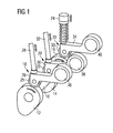
- Fig. 1 schematically shows a cam follower assembly for an internal combustion engine.
- the internal combustion engine includes a camshaft 10 having a plurality of cams 12, 14, 16.
- a plurality of cam followers 18, 20, 22 are arranged to trace the movement of cams 12, 14, 16 by contacting the same.
- Cam 12 may operate, for example, an inlet valve arranged in an inlet of a combustion chamber of a cylinder of the internal combustion engine via cam follower 18.
- Cam 14 may operate, for example, an outlet valve arranged in an outlet of the combustion chamber via cam follower 20.
- Cam 16 may operate, for example, an injection device for injecting fuel into the combustion chamber via cam follower 22. It should be appreciated that the above example is not intended to limit the present disclosure to the configuration shown in Fig. 1 , and that one or more of cams 12, 14, 16 and cam followers 18, 20, 22 may be omitted.
- Cam follower 18 comprises an operating lever formed, for example, as an oscillating arm which may trace the stroke of cam 12 via a roll 25 supported on a bracket 26 and transmit the same to the inlet valve via a rod 28.
- cam follower 20 is provided with an operating lever including a bracket 30 and may trace the stroke of cam 14 via a roll 29 supported on bracket 30 and transmit the same to the outlet valve via a rod 32.
- the stroke of cam 16 may be traced by a roll 33 mounted on a bracket 34 arranged at the end of an operating lever of cam follower 22 and transmitted to the injection device by a piston 24.
- the operating levers are rotatably supported, for example, on disks 36, 38, 40.
- the timings of the inlet valve and the outlet valve and, optionally, the injection timing may be controlled by adjusting, for example, the positions of disks 36, 38, 40, which may be formed as eccentrics.
- cam follower 18 is shown in more detail. It should be appreciated that the configuration of cam followers 20, 22 may be identical to the configuration of cam follower 18.
- cam follower 18 includes bracket 26, roll 25, a bushing 27 and an axis 23 mounted on bracket 26.
- Axis 23 is fixedly mounted in bores of bracket 26, for example, by press fitting or the like.
- Bushing 27 is mounted on axis 23.
- roll 25 is rotatably mounted on bushing 27 in a known manner. It will be appreciated that, in other embodiments, bushing 27 may be omitted, and roll 25 may be directly mounted on axis 23.
- Roll 25 is configured to roll on cam 12 upon rotation of camshaft 10. When camshaft 10 rotates, movement of roll 25 is transmitted to, for example, the inlet valve of the associated cylinder via rod 28.
- roll 25 may receive impact forces from cam 12. This may lead to end pressures being applied to the ends of roll 25.
- roll 25 includes recesses formed at the ends of the same.
- the recesses are formed as relief chamfers 41, 43. This increases the flexibility of roll 25 near the ends of the same, and reduces the end pressures applied to roll 25 and the optional bushing 27 during rotation of camshaft 10. In particular, it reduces or avoids pressing of the ends of roll 25 against the ends of bushing 27 (or axis 23 in case bushing 27 is omitted) at a contact interface 42 formed between roll 25 and bushing 27 (or between roll 25 and axis 23 in case bushing 27 is omitted).
- roll 25 includes a hollow cylindrical body having an outer surface 25a, an inner surface 25b, a first end face 25c and a second end face 25d. Roll 25 extends along a longitudinal direction parallel to axis 23 with a length 1 from first end face 25c to second end face 25d. Further, the hollow cylindrical body of roll 25 has a wall thickness t.
- bushing 27 is formed as a hollow cylindrical body and extends along the longitudinal direction of axis 23 with the same length 1 as roll 25. It should be appreciated that in other embodiments a length of bushing 27 can be different from the length 1 of roll 25.
- Bushing 27 also includes an outer surface 27a, an inner surface 27b, a first end face 27c adjacent to first end face 25c of roll 25 and a second end face 27d adjacent to second end face 25d of roll 25.
- contact interface 42 is formed between inner surface 25b of roll 25 and outer surface 27a of bushing 27. It should be appreciated that, in case bushing 27 is omitted, contact interface 42 will be formed between roll 25 and axis 23.
- the term "contact interface” refers to the surfaces of roll 25 and bushing 27 or axis 23 that are in contact during tracing of the movement of cam 12 by cam follower 18.
- the term "the contact interface includes a recess” is to be understood such that a recess is formed in one of the surfaces forming the contact interface. In other words, this term is to be understood such that a recess is formed in at least one of inner surface 25b of roll 25 and outer surface 27a of bushing 27, if present.
- the end pressure at the ends of roll 25 is reduced or avoided by providing a recessed portion of contact interface 42 adjacent to first and/or second end faces 25c, 25d of roll 25.
- the recessed portion is formed as relief chamfers 41, 43.
- Each of relief chamfers 41, 43 is formed at one end of roll 25 in the longitudinal direction and extends radially inward from the associated one of first and second end faces 25c, 25d to inner surface 25b of roll 25. It is obvious that relief chamfers 41, 43 are formed to extend in the circumferential direction of roll 25, i.e., as a continuous relief chamfer that extends circumferentially.
- each of relief chamfers 41, 43 has an extension d in the longitudinal direction and an extension h in the radial direction.
- the extension d will be referred to as the length of the chamfer
- the extension h will be referred to as the height of the chamfer.
- Each of relief chamfers 41, 43 has a size such that a ratio of the product of the length d and the height h to the square of the wall thickness t is greater than about 0.05.
- the amount of material that is removed when relief chamfers 41, 43 are formed has a predetermined relation to the thickness of roll 25. According to the present disclosure, a substantial amount of material is removed in order to achieve the desired flexibility of the ends of roll 25.
- the relation may be such that the ratio of the product of the length d and the height h to the square of the wall thickness t is greater than a predetermined value, for example, about 0.05 or about 0.1. This may be achieved, for example, by providing each of relief chamfers 41, 43 with a length d that is greater than about 0.25 times the wall thickness t and/or a height h that is greater than about 0.25 times the wall thickness t.
- the recessed portion of the contact interface 42 is formed as relief chamfers 41, 43 including a chamfered surface extending from end faces 25c, 25d to inner surface 25b.
- the relief chamfers may be formed as a step, i.e., with a rectangular cross-section.
- the relief chamfers may include a curved surface, for example, a concave or convex surface extending from end faces 25c, 25d to inner surface 25b.
- the relation between the height h and the length d of the relief chamfers to the wall thickness t may be the same as for relief chamfers 41, 43.
- the relief chamfers may be formed by machining end faces 25c, 25d in an appropriate manner, for example, by end milling or the like.
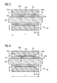
- Fig. 4 another exemplary embodiment of cam follower 18 is shown in more detail.
- roll 25 and bushing 27 substantially have the same configuration as in the embodiment shown in Fig. 3 such that only the differences will be described.
- a further recessed portion of contact interface 42 is formed in bushing 27.
- chamfers 45, 47 are formed adjacent to end faces 27c, 27d of bushing 27 to substantially face relief chamfers 41, 43 of roll 25.
- each of chamfers 45, 47 may have a length in the longitudinal direction that is the same as the length d of chamfers 41, 43.
- the length of chamfers 41, 43 and chamfers 45, 47 may be different.
- Chamfers 45 and 47 may have the same or a different shape as chamfers 41, 43.
- each of relief chamfers 45, 47 may have a size such that a ratio of the product of the length and the height of the same to the square of the wall thickness of bushing 27 is greater than about 0.05, for example, greater than about 0.1.
- the end pressures at the ends of roll 25 due to impact forces received from cam 12 can be reduced even further.
- the recesses in bushing 27 may also be formed as steps or curved surfaces.
- the recessed portion of the contact interface included chamfers 41, 43 or similar recesses formed in roll 25, it is also contemplated that, in case bushing 27 is present, the recessed portion of contact interface 42 may only be formed in bushing 27. In other words, no relief chamfers 41, 43 or similar recesses may be formed in roll 25. However, it is preferable that such recesses are formed in roll 25 adjacent to end faces 25c, 25d to achieve the desired flexibility of roll 25.
- the structure of the roll of the cam follower according to the present disclosure it is possible to reduce or avoid end pressures being applied to the ends of the roll due to impact forces received from the associated cam. This may improve the durability and reliability of the cam follower including the roll.
- relief chamfers are formed in the end faces of the roll to improve the flexibility of the ends of the same. Further, in case the roll is mounted on the corresponding axis via a bushing, the end pressures may further be reduced by also providing relief chamfers in the bushing facing the relief chamfers of the roll. This may be applied both to rolls with and without a crowned profile.
Landscapes
- Engineering & Computer Science (AREA)
- Mechanical Engineering (AREA)
- General Engineering & Computer Science (AREA)
- Valve Device For Special Equipments (AREA)
- Valve-Gear Or Valve Arrangements (AREA)
Priority Applications (2)
| Application Number | Priority Date | Filing Date | Title |
|---|---|---|---|
| EP14155193.7A EP2907982A1 (fr) | 2014-02-14 | 2014-02-14 | Galet suiveur de came pour moteur à combustion interne |
| CN201520101818.2U CN204476489U (zh) | 2014-02-14 | 2015-02-12 | 用于内燃机的凸轮随动件 |
Applications Claiming Priority (1)
| Application Number | Priority Date | Filing Date | Title |
|---|---|---|---|
| EP14155193.7A EP2907982A1 (fr) | 2014-02-14 | 2014-02-14 | Galet suiveur de came pour moteur à combustion interne |
Publications (1)
| Publication Number | Publication Date |
|---|---|
| EP2907982A1 true EP2907982A1 (fr) | 2015-08-19 |
Family
ID=50101779
Family Applications (1)
| Application Number | Title | Priority Date | Filing Date |
|---|---|---|---|
| EP14155193.7A Withdrawn EP2907982A1 (fr) | 2014-02-14 | 2014-02-14 | Galet suiveur de came pour moteur à combustion interne |
Country Status (2)
| Country | Link |
|---|---|
| EP (1) | EP2907982A1 (fr) |
| CN (1) | CN204476489U (fr) |
Citations (3)
| Publication number | Priority date | Publication date | Assignee | Title |
|---|---|---|---|---|
| JPH11247845A (ja) * | 1998-02-27 | 1999-09-14 | Nippon Seiko Kk | ローラ支持用軸受装置 |
| EP1574677A1 (fr) * | 2004-03-10 | 2005-09-14 | Toyota Jidosha Kabushiki Kaisha | Dispositif de commande de soupapes avec culbuteur à roulette |
| JP2007333025A (ja) * | 2006-06-13 | 2007-12-27 | Nsk Ltd | 転がり摺動部品の製造方法 |
-
2014
- 2014-02-14 EP EP14155193.7A patent/EP2907982A1/fr not_active Withdrawn
-
2015
- 2015-02-12 CN CN201520101818.2U patent/CN204476489U/zh not_active Expired - Fee Related
Patent Citations (3)
| Publication number | Priority date | Publication date | Assignee | Title |
|---|---|---|---|---|
| JPH11247845A (ja) * | 1998-02-27 | 1999-09-14 | Nippon Seiko Kk | ローラ支持用軸受装置 |
| EP1574677A1 (fr) * | 2004-03-10 | 2005-09-14 | Toyota Jidosha Kabushiki Kaisha | Dispositif de commande de soupapes avec culbuteur à roulette |
| JP2007333025A (ja) * | 2006-06-13 | 2007-12-27 | Nsk Ltd | 転がり摺動部品の製造方法 |
Also Published As
| Publication number | Publication date |
|---|---|
| CN204476489U (zh) | 2015-07-15 |
Similar Documents
| Publication | Publication Date | Title |
|---|---|---|
| US9422840B2 (en) | Hydraulic valve for an internal combustion engine | |
| JP6001704B2 (ja) | コネクティングロッドおよび内燃機関 | |
| EP2677124B1 (fr) | Poussoir à galet pour moteur à combustion interne | |
| CN105723070A (zh) | 具有支持活塞的活塞式发动机 | |
| US20130167788A1 (en) | Valve Control for at Least One of an Internal Combustion Engine | |
| CN104919148B (zh) | 凸轮轴调节器 | |
| EP3165723A1 (fr) | Appareil de commande de temporisation d'ouverture/fermeture de soupape | |
| EP3204642B1 (fr) | Unité de pompe pour fournir du carburant, de préférence du carburant diesel, à un moteur à combustion interne | |
| US9695745B2 (en) | Connecting rod and internal combustion engine | |
| US9745934B2 (en) | Mechanical system forming a cam follower or a rocker arm | |
| EP2907982A1 (fr) | Galet suiveur de came pour moteur à combustion interne | |
| US9797279B2 (en) | Exhaust valve and an engine assembly including the exhaust valve having a pressure relief apparatus | |
| US10082052B2 (en) | Hydraulic lash adjuster | |
| US20200263645A1 (en) | Assembled roller tappet | |
| US20150218982A1 (en) | Rocker arm assembly | |
| US7146951B2 (en) | Switchable cam follower | |
| JP2015135058A (ja) | 油圧制御弁 | |
| CN105339708A (zh) | 可调节凸轮轴 | |
| CN104285044A (zh) | 具有带不对齐限制端盖的阀门挺杆的内燃发动机 | |
| JP7224286B2 (ja) | バルブステムシール | |
| US10690017B2 (en) | Hydraulic lash adjuster assembly sleeves | |
| US20160040563A1 (en) | Hydraulic lash adjuster anti-rotation clip | |
| JP6161703B2 (ja) | カムシャフトアッセンブリ及びその製造方法 | |
| GB2536808A (en) | Connecting rod and internal combustion engine | |
| GB2620590B (en) | Rocker arm for a piston engine valve, valve assembly, and piston engine |
Legal Events
| Date | Code | Title | Description |
|---|---|---|---|
| PUAI | Public reference made under article 153(3) epc to a published international application that has entered the european phase |
Free format text: ORIGINAL CODE: 0009012 |
|
| AK | Designated contracting states |
Kind code of ref document: A1 Designated state(s): AL AT BE BG CH CY CZ DE DK EE ES FI FR GB GR HR HU IE IS IT LI LT LU LV MC MK MT NL NO PL PT RO RS SE SI SK SM TR |
|
| AX | Request for extension of the european patent |
Extension state: BA ME |
|
| STAA | Information on the status of an ep patent application or granted ep patent |
Free format text: STATUS: THE APPLICATION IS DEEMED TO BE WITHDRAWN |
|
| 18D | Application deemed to be withdrawn |
Effective date: 20160220 |