EP2908099B1 - Vorrichtung zur Messung des Drehwinkels zweier relativ zueinander rotierender Objekte - Google Patents
Vorrichtung zur Messung des Drehwinkels zweier relativ zueinander rotierender Objekte Download PDFInfo
- Publication number
- EP2908099B1 EP2908099B1 EP14155096.2A EP14155096A EP2908099B1 EP 2908099 B1 EP2908099 B1 EP 2908099B1 EP 14155096 A EP14155096 A EP 14155096A EP 2908099 B1 EP2908099 B1 EP 2908099B1
- Authority
- EP
- European Patent Office
- Prior art keywords
- elements
- analyzer
- polarization
- analyzer elements
- receiver
- Prior art date
- Legal status (The legal status is an assumption and is not a legal conclusion. Google has not performed a legal analysis and makes no representation as to the accuracy of the status listed.)
- Not-in-force
Links
Images


Classifications
-
- G—PHYSICS
- G01—MEASURING; TESTING
- G01D—MEASURING NOT SPECIALLY ADAPTED FOR A SPECIFIC VARIABLE; ARRANGEMENTS FOR MEASURING TWO OR MORE VARIABLES NOT COVERED IN A SINGLE OTHER SUBCLASS; TARIFF METERING APPARATUS; MEASURING OR TESTING NOT OTHERWISE PROVIDED FOR
- G01D5/00—Mechanical means for transferring the output of a sensing member; Means for converting the output of a sensing member to another variable where the form or nature of the sensing member does not constrain the means for converting; Transducers not specially adapted for a specific variable
- G01D5/26—Mechanical means for transferring the output of a sensing member; Means for converting the output of a sensing member to another variable where the form or nature of the sensing member does not constrain the means for converting; Transducers not specially adapted for a specific variable characterised by optical transfer means, i.e. using infrared, visible, or ultraviolet light
- G01D5/32—Mechanical means for transferring the output of a sensing member; Means for converting the output of a sensing member to another variable where the form or nature of the sensing member does not constrain the means for converting; Transducers not specially adapted for a specific variable characterised by optical transfer means, i.e. using infrared, visible, or ultraviolet light with attenuation or whole or partial obturation of beams of light
- G01D5/34—Mechanical means for transferring the output of a sensing member; Means for converting the output of a sensing member to another variable where the form or nature of the sensing member does not constrain the means for converting; Transducers not specially adapted for a specific variable characterised by optical transfer means, i.e. using infrared, visible, or ultraviolet light with attenuation or whole or partial obturation of beams of light the beams of light being detected by photocells
- G01D5/344—Mechanical means for transferring the output of a sensing member; Means for converting the output of a sensing member to another variable where the form or nature of the sensing member does not constrain the means for converting; Transducers not specially adapted for a specific variable characterised by optical transfer means, i.e. using infrared, visible, or ultraviolet light with attenuation or whole or partial obturation of beams of light the beams of light being detected by photocells using polarisation
- G01D5/345—Polarising encoders
-
- G—PHYSICS
- G01—MEASURING; TESTING
- G01D—MEASURING NOT SPECIALLY ADAPTED FOR A SPECIFIC VARIABLE; ARRANGEMENTS FOR MEASURING TWO OR MORE VARIABLES NOT COVERED IN A SINGLE OTHER SUBCLASS; TARIFF METERING APPARATUS; MEASURING OR TESTING NOT OTHERWISE PROVIDED FOR
- G01D5/00—Mechanical means for transferring the output of a sensing member; Means for converting the output of a sensing member to another variable where the form or nature of the sensing member does not constrain the means for converting; Transducers not specially adapted for a specific variable
- G01D5/26—Mechanical means for transferring the output of a sensing member; Means for converting the output of a sensing member to another variable where the form or nature of the sensing member does not constrain the means for converting; Transducers not specially adapted for a specific variable characterised by optical transfer means, i.e. using infrared, visible, or ultraviolet light
- G01D5/32—Mechanical means for transferring the output of a sensing member; Means for converting the output of a sensing member to another variable where the form or nature of the sensing member does not constrain the means for converting; Transducers not specially adapted for a specific variable characterised by optical transfer means, i.e. using infrared, visible, or ultraviolet light with attenuation or whole or partial obturation of beams of light
- G01D5/34—Mechanical means for transferring the output of a sensing member; Means for converting the output of a sensing member to another variable where the form or nature of the sensing member does not constrain the means for converting; Transducers not specially adapted for a specific variable characterised by optical transfer means, i.e. using infrared, visible, or ultraviolet light with attenuation or whole or partial obturation of beams of light the beams of light being detected by photocells
- G01D5/347—Mechanical means for transferring the output of a sensing member; Means for converting the output of a sensing member to another variable where the form or nature of the sensing member does not constrain the means for converting; Transducers not specially adapted for a specific variable characterised by optical transfer means, i.e. using infrared, visible, or ultraviolet light with attenuation or whole or partial obturation of beams of light the beams of light being detected by photocells using displacement encoding scales
- G01D5/34707—Scales; Discs, e.g. fixation, fabrication, compensation
- G01D5/34715—Scale reading or illumination devices
-
- G—PHYSICS
- G01—MEASURING; TESTING
- G01D—MEASURING NOT SPECIALLY ADAPTED FOR A SPECIFIC VARIABLE; ARRANGEMENTS FOR MEASURING TWO OR MORE VARIABLES NOT COVERED IN A SINGLE OTHER SUBCLASS; TARIFF METERING APPARATUS; MEASURING OR TESTING NOT OTHERWISE PROVIDED FOR
- G01D5/00—Mechanical means for transferring the output of a sensing member; Means for converting the output of a sensing member to another variable where the form or nature of the sensing member does not constrain the means for converting; Transducers not specially adapted for a specific variable
- G01D5/26—Mechanical means for transferring the output of a sensing member; Means for converting the output of a sensing member to another variable where the form or nature of the sensing member does not constrain the means for converting; Transducers not specially adapted for a specific variable characterised by optical transfer means, i.e. using infrared, visible, or ultraviolet light
- G01D5/32—Mechanical means for transferring the output of a sensing member; Means for converting the output of a sensing member to another variable where the form or nature of the sensing member does not constrain the means for converting; Transducers not specially adapted for a specific variable characterised by optical transfer means, i.e. using infrared, visible, or ultraviolet light with attenuation or whole or partial obturation of beams of light
- G01D5/34—Mechanical means for transferring the output of a sensing member; Means for converting the output of a sensing member to another variable where the form or nature of the sensing member does not constrain the means for converting; Transducers not specially adapted for a specific variable characterised by optical transfer means, i.e. using infrared, visible, or ultraviolet light with attenuation or whole or partial obturation of beams of light the beams of light being detected by photocells
- G01D5/347—Mechanical means for transferring the output of a sensing member; Means for converting the output of a sensing member to another variable where the form or nature of the sensing member does not constrain the means for converting; Transducers not specially adapted for a specific variable characterised by optical transfer means, i.e. using infrared, visible, or ultraviolet light with attenuation or whole or partial obturation of beams of light the beams of light being detected by photocells using displacement encoding scales
- G01D5/3473—Circular or rotary encoders
Definitions
- the invention relates to a device for measuring the angle of rotation of two relatively rotating objects according to the preamble of patent claim 1.
- the angle of rotation of the rotating object is measured relative to a stationary object.
- the rotating object may be the rotating shaft of an engine relative to a stationary machine part.
- a scale provided on the rotating object can be both incremental and absolute. It is desirable to be able to perform a measurement of the relative rotational movement which is as insensitive to tolerances as possible, but which has a high degree of accuracy. Ideally, the measurement takes place without contact in order to avoid mechanical wear.
- a measuring principle using the optical polarization of light is known.
- an illuminated polarizer which, for example, rotates with the rotating object
- the polarization of the light of a light transmitter is influenced, which can be detected by means of a receiver.
- An upstream polarizing element is provided in front of the receiver, the receiver and the upstream polarizing element together forming an analyzer element.
- the relative intensity modulation in the analyzer element can be a measure of the angle of rotation.
- linearly polarizing polarizer Upon rotation of the linearly polarizing polarizer against the arranged in front of the receiver linearly polarizing Element, which can also be referred to as polarization filter, results in a sinusoidal intensity modulation over a rotation of 360 °. In order to be able to make a rotation angle calculation, therefore, advantageously two mutually rotated polarization filters are present.
- the EP 2 522 960 A1 discloses a device for measuring the angle of rotation of two relatively rotating objects, with a transmitter associated with the object, with a linear polarizer, wherein the transmitter and the polarizer rotate in dependence on the angle of rotation relative to each other, and with a receiver, the one by the upstream polarizing element passing light intensity measures to produce a rotation angle dependent signal.
- the receiver has at least two receiving elements, in front of which in each case a polarizing filter is arranged, wherein at least two of the polarization planes of the polarizing filter are arranged rotated against each other.
- the receiving elements are immediately adjacent and comparatively small, so that it can come by the wavelength dependent penetration depth of the light in the silicon in the boundary region of the adjacent receiving elements to a crosstalk of the received signals of the adjacent receiving elements.
- This crosstalk leads to a mutual influence of amplitude and phase of the detected signals and thus in the apparatus for measuring the angle of rotation of two relatively rotating objects to a measurement error in the angle measurement.
- EP 2 600 113 A1 discloses a device having the features of the preamble of claim 1.
- the object of the invention is to develop a device for measuring the angle of rotation of two relatively rotating objects such that in the receiver measurement errors, in particular measurement errors due to crosstalk between different receiving elements in the angle measurement is reduced, in particular avoided.
- two analyzer elements with the same polarization plane of e.g. 0 ° may not be arranged immediately next to each other, in particular in contact with each other, but at least one analyzer element with a different polarization plane of e.g. 90 ° between the two analyzer elements must be arranged with the same polarization plane of 0 °.
- the groups of analyzer elements consist of pairings of 0 ° and 90 °, 22.5 ° and 112.5 °, 45 ° and 135 °, and 67.5 ° and 157.5 °.
- the invention provides that in a row two groups of analyzer elements are arranged, the polarization planes are rotated by 90 ° from each other, wherein adjacent analyzer elements have different polarization planes.
- Analyzer elements with polarization planes which have an angular offset of 90 ° can compensate each other in their crosstalk behavior.
- only the amplitude but not the phase of the signals of the actual analyzer element is influenced, as long as the analyzer element operates in its linear region.
- the fact that exactly two types of analyzer elements are arranged in a row whose polarization planes are rotated by 90 ° from each other, wherein adjacent analyzer elements have different polarization levels, the crosstalk does not lead to a phase error.
- Such a line with analyzer elements or receiving elements is therefore intrinsically invariant to crosstalk. Due to the staggered arrangement, crosstalk to an analyzer element or receiving element of an adjacent line always occurs both through an analyzer element or receiving element of one type and an analyzer element or receiving element of the other type, these influences being due to the polarization planes rotated by 90 ° relative to one another cancel each other out in their influence on the phase. Such an arrangement thus makes it possible, in a particularly effective manner, to reduce or avoid an influence of crosstalk on the measurement signal.
- the groups of analyzer elements in at least two, preferably four or eight, adjacent rows are different from each other.
- the receiver is designed as an integrated sensor, in which in particular an optoelectronic sensor and a polarization filter structure are arranged together on a semiconductor substrate. Especially with such receivers, a reduction or complete avoidance of the influence of crosstalk is desirable.
- a particularly preferred embodiment of the invention provides that only the signals of the analyzer elements which are completely surrounded by further analyzer elements are used to determine the rotation angle-dependent signal. Since analyzer elements at the edge can not be excluded from crosstalk due to the asymmetrical arrangement of adjacent analyzer elements, and an optimized reduction in the influence of crosstalk is only achieved in the internal analyzer elements, the evaluation can be further improved and the measurement error further reduced. if only the analyzer elements which are completely surrounded by further analyzer elements are evaluated. However, the analyzer elements arranged at the edge generate the required crosstalk on the analyzer elements which are adjacent to the inside, in order to maintain the symmetry for the analyzed analyzer elements, but are advantageously not evaluated themselves since the influence of crosstalk is generally not optimally reduced in them.
- FIG. 1 shows a device for measuring the angle of rotation of two relatively rotating objects.
- only one object is designed to be rotating, namely a shaft 14, for example of a motor, wherein the angle of rotation of the shaft 14 with respect to a fixed part, for example, the motor housing or a fixed machine part to be determined.
- the device has a light source 10, which is fixedly arranged and can be associated with the fixed part, for example.
- the light source 10 may, for example, emit unpolarized or partially polarized light and in particular be designed as an LED.
- the rotating shaft 14 is associated with a reflector 16 which rotates with the shaft 14, in front of which a polarizer 12, likewise rotating with the shaft 14 and designed, for example, as a polarization filter, is arranged.
- the polarizer 12 may be formed as a "wire grid" polarizer or as a plasmonic polarizer, so that it can reflect polarized light.
- the reflector 16 can also be designed either as a diffusely reflecting or absorbing element in order to destroy the polarization obtained when the light passes through the polarizer 12 for the first time.
- a receiver 20 is provided, in front of which a polarization filter structure 22 is arranged.
- the receiver 20 has at least one two-dimensional array composed of lines 21, 21 ', 21 ", 21'", on which receiving elements with in each case upstream polarization filter elements of the polarization filter structure 22 are arranged.
- the receiving elements with the respectively upstream polarization filter elements form respective analyzer elements 25, 25 ', 25 ", 25"', 26 for detecting the angle signals.
- the receiver 20 is also fixedly arranged and may for example be associated with the fixed part.
- Various embodiments of the receiver 20 with the polarization filter structure 22 and the arrangement of the analyzer elements 25, 25 ', 25 ", 25”', 26 are based on the FIGS. 2 to 5 explained.
- FIG. 2 shows a schematic representation of a first embodiment of a receiver 20 with an inventive arrangement of the analyzer elements 25.
- the receiver 20 has a two-dimensional, consisting of several rows 21 array on which a plurality of analyzer elements 25 are arranged.
- the analyzer elements 25 have different polarization directions or angles, which are 0 °, 22.5 °, 45 °, 67.5 °, 90 °, 112.5 °, 135 ° and 157.5 °.
- the analyzer elements 25 are arranged on the array so that they can be assigned to four groups A, B, C, D of analyzer elements 25, each consisting of a pair of analyzer elements 25.
- the pairs of analyzer elements 25 are characterized by an angular offset of 90 ° to each other, so that in the inventive arrangement four pairs of analyzer elements with the polarization directions 0 ° and 90 °, 22.5 ° and 112.5 °, 45 ° and 135th °, and 67.5 ° and 157.5 °.
- the groups A, B, C, D of analyzer elements 25 are provided in a defined arrangement with each other in the rows of the array such that an internal analyzer element 26 is defined by three groups B, C, D of analyzer elements 25 in both the horizontal and vertical directions Surrounded by the direction of the array.
- the respective analyzer elements 25 with the same polarization plane, such as 0 ° are arranged in the rows of the array in such a way that they are not immediately adjacent to one another, in particular in direct contact with each other, but by three analyzer elements with a different polarization plane in horizontal, namely 22.5 °, 90 ° and 112.5 °, and more vertical, namely 45 °, 90 ° and 135 °, direction and by an analyzer element with the polarization plane 67.5 ° in the diagonal direction spaced.
- FIG. 3 is a schematic representation of another embodiment of an arrangement, not part of the invention, of a receiver 20 'having a polarizing filter structure.
- the receiver 20 ' also has a plurality of lines 21', in each of which a plurality of analyzer elements 25 'are arranged.
- the analyzer elements 25 ' preferably have a length l and a width b, the length l arranged in the longitudinal direction of the line 21' being a distance between two centers Z of adjacently arranged analyzer elements 25 '. is reproduced and in particular advantageously twice as large as the width b of the analyzer elements 25 '.
- the receiver 20 ' has twelve rows 21', with six or seven analyzer elements 25 'arranged in each row.
- the analyzer elements 25 ' are arranged in such a way that adjacent lines 21' are each offset by half the length l of the analyzer element 25 'from one another in the longitudinal direction of the line 21'. This results in a kind of brick arrangement.
- a polarization filter is arranged in front of each of the analyzer elements 25 '.
- the given number of degrees represents the rotation of the polarization plane of the polarization filter arranged in front of the corresponding analyzer element 25 'with respect to an angle of 0 °.
- each of the lines 21 ' is arranged exactly one group of two analyzer elements 25', wherein the two analyzer elements 25 'differ in that their polarization planes are rotated by 90 ° to each other.
- the two analyzer elements 25' are arranged alternately.
- a line 21 'adjacent analyzer elements 25' thus always differ in their polarization direction by 90 °. Since the signal curves detected with these analyzer elements 25 'are exactly opposite in phase, crosstalk only leads to an influence on the amplitude, but not to an influence to the phase of the signal.
- Each of the rows 21 ' is thus intrinsically invariant in phase to crosstalk.
- the analyzer elements 25 'with equal polarization planes in the horizontal direction of the array are always spaced apart by exactly one analyzer element 25' with a different polarization plane.
- this analyzer element 26 learns, for example, crosstalk contributions from the two lines 21 lying above it 'arranged analyzer elements 25' with the phase angles of the polarizing filter of 135 ° and 45 °, but which are rotated by 90 ° to each other, thus are exactly opposite in phase and therefore compensate in the analyzer element 26.
- the analyzer element 26 experiences crosstalk contributions from the two in the underlying line 21 'arranged analyzer elements 25' with the angular positions of the polarization filter of 168.75 ° and 78.75 °, which are also rotated exactly 90 ° to each other, so that their signal contributions are also out of phase and therefore compensate in the analyzer element 26.
- analyzer elements 25 'in each of the lines 21' It is possible to provide the same types of analyzer elements 25 'in each of the lines 21'.
- eight different groups A to H of analyzer elements 25 'are used namely the groups 0 ° and 90 °, 45 ° and 135 °, 22.5 ° and 112.5 °, 157 , 5 ° and 67.5 °, 11.25 ° and 101.25 °, 146.25 ° and 56.25 °, 123.75 ° and 33.75 ° and 78.75 ° and 168.75 °.
- These groups can be arranged in any order in any number of rows.
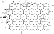
- FIG. 4 shows another embodiment of a receiver 20 "with an arrangement, which is not part of the invention, the analyzer elements 25".
- the receiver 20 has a plurality of analyzer elements 25" arranged in a plurality of lines 21 " FIG. 4 in the analyzer elements 25 "indicated angle data again correspond to the rotation of the polarization plane of the corresponding analyzer element 25" with respect to the orientation of 0 °.
- FIG. 4 The arrangement shown differs from that in FIG. 3 Essentially, the fact that the analyzer elements 25 "are formed not as rectangular but as hexagons The points indicated on the sides of the arrangement mean that the arrangement can be continued in all four directions as desired with further lines 21" and further analyzer elements 25 "
- the hexagonal geometry may include both regular hexagons and irregular hexagons.
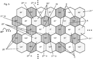
- FIG. 5 Fig. 12 is a schematic representation of another embodiment of a receiver 20 '''with an arrangement not part of the invention, the analyzer elements 25'''.
- the receiver 20 ''' has a plurality of analyzer elements 25''' arranged in rows 21 ''.
- the angle indicated in each of the analyzer elements 25 '''again refers to the rotation of the polarization plane of the corresponding polarizing filter from the 0 ° direction.
- the analyzer elements 25 '"spaced apart from the edge of the receiver 20'" are surrounded by six analyzer elements 25 '"whose polarization directions are arranged as follows.
- the analyzer element 26 is viewed in the third row 21 "at the third position from the left, which has a direction of polarization plane of 80 °, for example, and the analyzer element 26 is surrounded by six analyzer elements 27""i.
- the analyzer elements 27 "'- i form two groups A, B, namely a group A with the analyzer elements 27"' - 1, 27 "'- 3 and 27"' - 5 and a second group B with the analyzer elements 27 "'- 2, 27"' - 4 and 27 "'- 6.
- the polarization planes of two pairs of the three analyzer elements 27"' - 3 and 27 "'- 5, 27"' are shown.
- the direction of polarization of the receiving elements 27 "'- i can be identical in both groups A, B. In the present case, however, the polarization planes 0 °, 60 ° and 120 ° are arranged in the first group A, while in the second group B the polarization directions 40 °, 100 ° and 160 ° are arranged.
- the inner analyzer element 26 with two further analyzer elements 25 '" forms a third group C having the polarization directions 20 °, 80 ° and 140 °.
- the three groups A, B, C together form the receiver 20'".
Landscapes
- Physics & Mathematics (AREA)
- General Physics & Mathematics (AREA)
- Optical Transform (AREA)
Description
- Die Erfindung betrifft eine Vorrichtung zur Messung des Drehwinkels zweier relativ zueinander rotierender Objekte gemäß dem Oberbegriff des Patentanspruchs 1.
- Für viele Anwendungen ist es von grundlegender Bedeutung, den Drehwinkel eines rotierenden Objektes zu messen. Im Allgemeinen wird dabei der Drehwinkel des rotierenden Objektes relativ zu einem feststehenden Objekt gemessen. Beispielsweise kann es sich bei dem rotierenden Objekt um die rotierende Welle eines Motors relativ zu einem feststehenden Maschinenteil handeln. Ein auf dem rotierenden Objekt vorgesehener Maßstab kann dabei sowohl inkrementell als auch absolut sein. Dabei ist es wünschenswert, eine möglichst toleranzunempfindliche Messung der relativen Drehbewegung durchführen zu können, welche jedoch eine hohe Genauigkeit aufweist. Im Idealfall erfolgt die Messung berührungslos, um mechanischen Verschleiß zu vermeiden.
- Bekannt ist ein Messprinzip unter Ausnutzung der optischen Polarisation von Licht. Durch Drehung eines beleuchteten Polarisators, welcher sich beispielsweise mit dem rotierenden Objekt mit dreht, wird die Polarisation des Lichtes eines Lichtsenders beeinflusst, was mittels eines Empfängers detektierbar ist. Vor dem Empfänger ist ein vorgelagertes polarisierendes Element vorgesehen, wobei der Empfänger und das vorgelagerte polarisierende Element zusammen ein Analysatorelement bilden. Bei geeigneter Wahl der geometrischen Anordnung des Lichtsenders, des Polarisators und des aus dem Empfänger und dem vorgelagerten polarisierenden Element bestehenden Analysatorelements kann die relative Intensitätsmodulation im Analysatorelement ein Maß für den Drehwinkel sein. Bei Drehung des linear polarisierenden Polarisators gegen das vor dem Empfänger angeordnete linear polarisierende Element, das auch als Polarisationsfilter bezeichnet werden kann, ergibt sich eine sinusquadratförmige Intensitätsmodulation über eine Drehung um 360°. Um eine Drehwinkelberechnung vornehmen zu können, sind daher vorteilhafterweise zwei gegeneinander gedrehte Polarisationsfilter vorhanden.
- Die
EP 2 522 960 A1 offenbart eine Vorrichtung zur Messung des Drehwinkels zweier relativ zueinander rotierender Objekte, mit einem dem einen Objekt zugeordneten Sender, mit einem Linearpolarisator, wobei sich der Sender und der Polarisator in Abhängigkeit vom Drehwinkel relativ zueinander drehen, und mit einem Empfänger, der die durch das vorgelagerte polarisierende Element durchtretende Lichtintensität misst, um ein drehwinkelabhängiges Signal zu erzeugen. Dabei weist der Empfänger wenigstens zwei Empfangselemente auf, vor welchen jeweils ein Polarisationsfilter angeordnet ist, wobei wenigstens zwei der Polarisationsebenen der Polarisationsfilter gegeneinander verdreht angeordnet sind. - Insbesondere wenn der Empfänger als auf einem Siliziumchip integrierter Sensor, wie beispielsweise in der
EP 2 275 790 A2 beschrieben, ausgebildet ist, sind die Empfangselemente unmittelbar benachbart und vergleichsweise klein ausgebildet, so dass es durch die von der Wellenlänge abhängige Eindringtiefe des Lichtes in das Silizium im Grenzgebiet der benachbarten Empfangselemente zu einem Übersprechen der Empfangssignale der benachbarten Empfangselemente kommen kann. Dieses Übersprechen führt zu einer gegenseitigen Beeinflussung von Amplitude und Phase der detektierten Signale und damit in der Vorrichtung zur Messung des Drehwinkels zweier relativ zueinander rotierender Objekte zu einem Messfehler in der Winkelmessung. -
EP 2 600 113 A1 offenbart eine Vorrichtung mit den Merkmalen des Oberbegriffs des Anspruchs 1. - Die Aufgabe der Erfindung besteht darin, eine Vorrichtung zur Messung des Drehwinkels zweier relativ zueinander rotierender Objekte derart weiterzubilden, dass in dem Empfänger Messfehler, insbesondere Messfehler durch Übersprechen zwischen verschiedenen Empfangselementen, bei der Winkelmessung verringert, insbesondere vermieden, werden.
- Die Aufgabe der Erfindung wird gelöst durch eine Vorrichtung mit den Merkmalen des Anspruchs 1.
- Dies bedeutet, dass zwei Analysatorelemente mit der gleichen Polarisationsebene von z.B. 0° nicht unmittelbar nebeneinander, insbesondere in Kontakt miteinander, angeordnet sein dürfen, sondern mindestens ein Analysatorelement mit einer anderen Polarisationsebene von z.B. 90° zwischen den beiden Analysatorelementen mit der gleichen Polarisationsebene von 0° angeordnet sein muss.
- Gemäß einem weiteren bevorzugten Ausführungsbeispiel bestehen die Gruppen von Analysatorelementen aus Paarungen von 0° und 90°, 22,5° und 112,5°, 45° und 135°, und 67,5° und 157,5°.
- Die Erfindung sieht vor, dass in einer Zeile zwei Gruppen von Analysatorelementen angeordnet sind, deren Polarisationsebenen um 90° gegeneinander verdreht sind, wobei benachbarte Analysatorelemente unterschiedliche Polarisationsebenen aufweisen. Analysatorelementen mit Polarisationsebenen, welche einen Winkelversatz von 90° aufweisen, können sich gegenseitig in ihrem Übersprechverhalten kompensieren. Dadurch wird lediglich die Amplitude jedoch nicht die Phase der Signale des eigentlichen Analysatorelements beeinflusst, sofern das Analysatorelement in seinem linearen Bereich arbeitet. Dadurch, dass in einer Zeile genau zwei Typen von Analysatorelementen angeordnet sind, deren Polarisationsebenen um 90° gegeneinander verdreht sind, wobei benachbarte Analysatorelemente unterschiedliche Polarisationsebenen aufweisen, führt das Übersprechen nicht zu einem Phasenfehler. Eine derartige Zeile mit Analysatorelementen bzw. Empfangselementen ist daher in sich invariant gegenüber Übersprechen. Aufgrund der versetzten Anordnung tritt ein Übersprechen auf ein Analysatorelement bzw. Empfangselement einer benachbarten Zeile immer sowohl durch ein Analysatorelement bzw. Empfangselement des einen Typs und ein Analysatorelement bzw. Empfangselement des anderen Typs auf, wobei sich diese Einflüsse aufgrund der um 90° gegeneinander verdrehten Polarisationsebenen in ihrem Einfluss auf die Phase gegenseitig aufheben. Eine derartige Anordnung ermöglicht somit in besonders effektiver Weise eine Verringerung beziehungsweise ein Vermeiden eines Einflusses eines Übersprechens auf das Messsignal.
- Vorteilhafterweise sind die die Gruppen von Analysatorelementen in wenigstens zwei, vorzugsweise vier oder acht, angrenzenden Zeilen voneinander verschieden.
- Besonders bevorzugt ist der Empfänger als integrierter Sensor ausgebildet, bei welchem insbesondere ein optoelektronischer Sensor und eine Polarisationsfilterstruktur gemeinsam auf einem Halbleitersubstrat angeordnet sind. Insbesondere bei derartigen Empfängern ist eine Verringerung oder vollständige Vermeidung des Einflusses eines Übersprechens wünschenswert.
- Eine besonders bevorzugte Ausführungsform der Erfindung sieht vor, dass zur Bestimmung des drehwinkelabhängigen Signals lediglich die Signale der Analysatorelemente herangezogen werden, welche vollständig von weiteren Analysatorelementen umgeben sind. Da bei Analysatorelementen am Rand aufgrund der unsymmetrischen Anordnung von benachbarten Analysatorelementen nicht ausgeschlossen werden kann, dass ein Übersprechen erfolgt, und eine optimierte Verringerung des Einflusses des Übersprechens lediglich bei den innenliegenden Analysatorelementen erreicht wird, kann die Auswertung weiter verbessert und der Messfehler weiter verringert werden, wenn lediglich die Analysatorelemente ausgewertet werden, welche vollständig von weiteren Analysatorelementen umgeben sind. Die am Rand angeordneten Analysatorelemente erzeugen das erforderliche Übersprechen auf die innen angrenzenden Analysatorelemente, um die Symmetrie für die ausgewerteten Analysatorelemente zu wahren, werden vorteilhafterweise jedoch nicht selber ausgewertet, da bei ihnen der Einfluss des Übersprechens in der Regel nicht in optimaler Weise verringert ist.
- Vorteilhafte Ausgestaltungen und Weiterbildungen sowie weitere Vorteile der Erfindung sind den Unteransprüchen, der nachfolgenden Beschreibung und den Zeichnungen zu entnehmen. Im Folgenden wird die Erfindung anhand von Ausführungsbeispielen unter Bezugnahme auf die Zeichnungen im Einzelnen erläutert. In den Zeichnungen zeigen:
- Fig. 1
- eine schematische Darstellung einer Vorrichtung zur Messung des Drehwinkels zweier relativ zueinander rotierender Objekte,
- Fig. 2
- eine schematische Darstellung eines Ausführungsbeispiels des Empfängers mit Polarisationsfilterstruktur der Vorrichtung gemäß
Figur 1 , - Fig. 3
- eine schematische Darstellung eines weiteren Ausführungsbeispiels des Empfängers mit Polarisationsfilterstruktur der Vorrichtung gemäß
Figur 1 , das nicht Teil der Erfindung ist, - Fig. 4
- eine schematische Darstellung eines weiteren Ausführungsbeispiels des Empfängers mit Polarisationsfilterstruktur der Vorrichtung gemäß
Figur 1 , das nicht Teil der Erfindung ist, und - Fig. 5
- eine schematische Darstellung eines weiteren Ausführungsbeispiels des Empfängers mit Polarisationsfilterstruktur gemäß
Figur 1 , das nicht Teil der Erfindung ist. -
Figur 1 zeigt eine Vorrichtung zur Messung des Drehwinkels zweier relativ zueinander rotierender Objekte. Dabei ist vorliegend lediglich ein Objekt rotierend ausgebildet, nämlich eine Welle 14 beispielsweise eines Motors, wobei der Drehwinkel der Welle 14 in Bezug zu einem feststehenden Teil, beispielsweise dem Motorgehäuse oder einem feststehenden Maschinenteil, ermittelt werden soll. Die Vorrichtung weist eine Lichtquelle 10 auf, welche feststehend angeordnet ist und beispielsweise dem feststehenden Teil zugeordnet sein kann. Die Lichtquelle 10 kann beispielsweise unpolarisiertes oder teilpolarisiertes Licht aussenden und insbesondere als LED ausgebildet sein. - Der rotierenden Welle 14 ist ein sich mit der Welle 14 drehender Reflektor 16 zugeordnet, vor welchem ein ebenfalls mit der Welle 14 drehender Polarisator 12, welcher beispielsweise als Polarisationsfilter ausgebildet ist, angeordnet ist. Hierbei kann alternativ der Polarisator 12 als "Wire Grid" Polarisator oder als plasmonischer Polarisator ausgebildet sein, so dass er polarisiertes Licht reflektieren kann. Der Reflektor 16 kann ferner entweder als diffus reflektierendes oder absorbierendes Element ausgebildet sein, um die beim ersten Durchtritt des Lichtes durch den Polarisator 12 erhaltene Polarisation zu zerstören.
- Weiterhin ist ein Empfänger 20 vorgesehen, vor welchem eine Polarisationsfilterstruktur 22 angeordnet ist. Der Empfänger 20 weist zumindest ein zweidimensionales, aus Zeilen 21, 21', 21", 21'" bestehendes Array auf, auf dem Empfangselemente mit jeweils vorgeordneten Polarisationsfilterelementen der Polarisationsfilterstruktur 22 angeordnet sind. Die Empfangselemente mit den jeweils vorgeordneten Polarisationsfilterelementen bilden jeweilige Analysatorelemente 25, 25', 25", 25"', 26 zum Detektieren der Winkelsignale. Der Empfänger 20 ist ebenfalls feststehend angeordnet und kann beispielsweise dem feststehenden Teil zugeordnet sein. Verschiedene Ausführungsformen des Empfängers 20 mit der Polarisationsfilterstruktur 22 bzw. der Anordnung der Analysatorelementen 25, 25', 25", 25"', 26 werden anhand der
Figuren 2 bis 5 erläutert. - Abhängig vom Drehwinkel der rotierenden Welle 14 ändert sich die Intensität des Lichtes, welches in den Analysatorelementen 25, 25', 25", 25"', 26 detektiert wird.
Figur 2 zeigt in schematischer Darstellung ein erstes Ausführungsbeispiel eines Empfängers 20 mit einer erfindungsgemäßen Anordnung der Analysatorelemente 25. Der Empfänger 20 weist ein zweidimensionales, aus mehreren Zeilen 21 bestehendes Array auf, auf dem eine Mehrzahl von Analysatorelementen 25 angeordnet sind. - Die Analysatorelemente 25 weisen unterschiedliche Polarisationsrichtungen bzw. -winkel auf, die 0°, 22,5°, 45°, 67,5°, 90°, 112,5°, 135° und 157,5° betragen. Hierbei sind die Analysatorelemente 25 derart auf dem Array angeordnet, dass sie in vier Gruppen A, B, C, D von Analysatorelementen 25 zugeordnet werden können, die jeweils aus einem Paar von Analysatorelementen 25 bestehen.
- Die Paare von Analysatorelementen 25 zeichnen sich durch einen Winkelversatz von 90° zueinander aus, so dass sich bei der erfindungsgemäßen Anordnung vier Paarungen von Analysatorelementen mit den Polarisationsrichtungen 0° und 90°, 22,5° und 112,5°, 45° und 135°, und 67,5° und 157,5° ergeben.
- Die Gruppen A, B, C, D von Analysatorelementen 25 sind in einer definierten Anordnung zueinander in den Zeilen des Arrays vorgesehen, so dass ein innenliegendes Analysatorelement 26 durch drei Gruppen B, C, D von Analysatorelementen 25 sowohl in horizontaler Richtung als auch in vertikaler Richtung des Arrays umgeben ist.
- Durch diese Anordnung wird ein Übersprechen der einzelnen Analysatorelemente 25 innerhalb der Gruppe B, C, D kompensiert, so dass ein Einfluss des Übersprechens auf das zentral innenliegende Analysatorelement 26 reduzier- bzw. vermeidbar ist. Ferner ist mittels dieser Anordnung eine Kompensation des Übersprechens für acht Polarisationsrichtungen realisierbar.
- Ferner sind die jeweiligen Analysatorelemente 25 mit gleicher Polarisationsebene, wie z.B. 0°, derart in den Zeilen des Arrays angeordnet, dass sie nicht unmittelbar nebeneinander, insbesondere in direktem Kontakt zueinander, angeordnet sind, sondern durch drei Analysatorelemente mit einer anderen Polarisationsebene in waagerechter, nämlich 22,5°, 90° und 112,5°, und senkrechter, nämlich 45°, 90° und 135°, Richtung und durch ein Analysatorelement mit der Polarisationsebene 67,5° in diagonaler Richtung beabstandet.
- In der
Figur 3 ist in schematischer Darstellung ein weiteres Ausführungsbeispiel einer Anordnung, die nicht Teil der Erfindung ist, eines Empfängers 20' mit einer Polarisationsfilterstruktur gezeigt. Hierbei weist der Empfänger 20' ebenfalls mehrere Zeilen 21' auf, in welchen jeweils mehrere Analysatorelemente 25' angeordnet sind. - Abgesehen von einigen am Rand angeordneten Analysatorelementen 27 weisen die Analysatorelemente 25' bevorzugterweise eine Länge l und eine Breite b auf, wobei die Länge l, welche in Längsrichtung der Zeile 21' angeordnet ist, einen Abstand zwischen zwei Zentren Z von benachbart angeordneten Analysatorelementen 25' wiedergibt und insbesondere vorteilhafterweise doppelt so groß ist wie die Breite b der Analysatorelemente 25'.
- Beispielsweise weist der Empfänger 20' zwölf Zeilen 21' auf, wobei in jeder Zeile sechs oder sieben Analysatorelemente 25' angeordnet sind. Die Analysatorelemente 25' sind derart angeordnet, dass angrenzende Zeilen 21' jeweils um eine halbe Länge l des Analysatorelementes 25' gegeneinander in Längsrichtung der Zeile 21' versetzt angeordnet sind. Dadurch ergibt sich eine Art Backsteinanordnung. Vor jedem der Analysatorelemente 25' ist ein Polarisationsfilter angeordnet. Die in den Analysatorelementen 25' in
Figur 3 angegebene Gradzahl stellt die Verdrehung der Polarisationsebene des vor dem entsprechenden Analysatorelement 25' angeordneten Polarisationsfilters gegenüber einem Winkel von 0° dar. - In jeder der Zeilen 21' ist genau eine Gruppe aus zwei Analysatorelementen 25' angeordnet, wobei sich die beiden Analysatorelemente 25' dadurch unterscheiden, dass ihre Polarisationsebenen um 90° gegeneinander verdreht sind. In jeder der Zeilen 21' sind die beiden Analysatorelemente 25' abwechselnd angeordnet. In einer Zeile 21' benachbarte Analysatorelemente 25' unterscheiden sich somit immer in ihrer Polarisationsrichtung um 90°. Da die mit diesen Analysatorelementen 25' detektierten Signalverläufe genau gegenphasig sind, führt ein Übersprechen lediglich zu einem Einfluss auf die Amplitude, nicht jedoch zu einem Einfluss auf die Phase des Signals. Jede der Zeilen 21' ist somit in sich invariant hinsichtlich der Phase gegenüber Übersprechen.
- Aufgrund der Backsteinanordnung tragen jedoch in einer Zeile 21' benachbarte Analysatorelemente 25' jeweils zu gleichen Teilen zum Übersprechen auf ein Analysatorelement 25' in einer benachbarten Zeile 21' bei, sodass sich die Übersprechbeiträge in dem benachbarten Analysatorelement 25' ebenfalls kompensieren.
- Ferner sind durch die abwechselnde Anordnung die Analysatorelemente 25' mit gleichen Polarisationsebenen in waagerechter Richtung des Arrays immer durch genau ein Analysatorelement 25' mit einer anderen Polarisationsebene voneinander beabstandet.
- Betrachtet man beispielsweise ein innenliegendes Analysatorelement 26, dessen Polarisationsebene im Winkel von 0° angeordnet ist, welches sich im vorliegenden Beispiel insbesondere in der achten Zeile an dritter Stelle von links befindet, erfährt dieses Analysatorelement 26 beispielsweise Übersprechbeiträge von den beiden in der darüber liegenden Zeile 21' angeordneten Analysatorelementen 25' mit den Phasenlagen der Polarisationsfilter von 135° und 45°, welche jedoch um 90° zueinander gedreht sind, somit genau gegenphasig sind und sich daher in dem Analysatorelement 26 kompensieren. Weiterhin erfährt das Analysatorelement 26 Übersprechbeiträge von den beiden in der darunter liegenden Zeile 21' angeordneten Analysatorelementen 25' mit den Winkellagen der Polarisationsfilter von 168,75° und 78,75°, welche ebenfalls genau um 90° zueinander gedreht sind, so dass deren Signalbeiträge ebenfalls gegenphasig sind und sich daher in dem Analysatorelement 26 kompensieren.
- Es ist möglich, in jeder der Zeilen 21' gleiche Typen von Analysatorelementen 25' vorzusehen. In dem in
Figur 3 dargestellten Ausführungsbeispiel, das nicht Teil der Erfindung ist, werden jedoch acht verschiedene Gruppen A bis H von Analysatorelementen 25' verwendet, nämlich die Gruppen 0° und 90°, 45° und 135°, 22,5° und 112,5°, 157,5° und 67,5°, 11,25° und 101,25°, 146,25° und 56,25°, 123,75° und 33,75° sowie 78,75° und 168,75°. Diese Gruppen können in beliebiger Reihenfolge in beliebig vielen Zeilen angeordnet werden. - Bei einer Auswertung der in dem Empfänger 20' detektierten Signale können sämtliche Analysatorelemente 25' berücksichtigt werden. Vorteilhafterweise werden lediglich die innenliegenden Analysatorelemente 26, welche vollständig von Analysatorelementen 25' umgeben sind, ausgewertet, die außenliegenden Analysatorelemente 27 bei der Auswertung jedoch unberücksichtigt belassen, da in diesen gegebenenfalls die Übersprechbeiträge nicht optimal kompensiert sind.
-
Figur 4 zeigt ein weiteres Ausführungsbeispiel eines Empfängers 20" mit einer Anordnung, die nicht Teil der Erfindung ist, der Analysatorelemente 25". Der Empfänger 20" weist mehrere Analysatorelemente 25" auf, welche in mehreren Zeilen 21" angeordnet sind. Die inFigur 4 in den Analysatorelementen 25" angegebenen Winkelangaben entsprechen wiederum der Drehung der Polarisationsebene des entsprechenden Analysatorelementes 25" gegenüber der Ausrichtung von 0°. - Die in
Figur 4 dargestellte Anordnung unterscheidet sich von der inFigur 3 dargestellten Anordnung im Wesentlichen dadurch, dass die Analysatorelemente 25" nicht rechteckig, sondern als Sechseck ausgebildet sind. Die an den Seiten der Anordnung angedeuteten Punkte bedeuten, dass die Anordnung in alle vier Richtungen beliebig mit weiteren Zeilen 21" und weiteren Analysatorelementen 25" fortgesetzt werden kann. Die sechseckige Geometrie kann dabei sowohl regelmäßige Sechsecke als auch unregelmäßige Sechsecke umfassen. - In der
Figur 5 ist eine schematische Darstellung eines weiteren Ausführungsbeispiels eines Empfängers 20'" mit einer Anordnung, die nicht Teil der Erfindung ist, der Analysatorelemente 25'" gezeigt. Der Empfänger 20'" weist mehrere Analysatorelemente 25'" auf, welche in Zeilen 21'" angeordnet sind. Die in jedem der Analysatorelemente 25'" angegebene Winkelangabe bezieht sich wiederum auf die Verdrehung der Polarisationsebene des entsprechenden Polarisationsfilters gegenüber der Richtung von 0°. Bei dieser Anordnung der Analysatorelemente 25'" sind die vom Rand des Empfängers 20'" beabstandeten Analysatorelemente 25'" von sechs Analysatorelementen 25'" umgeben, deren Polarisationsrichtungen wie folgt angeordnet sind. - Beispielsweise wird dazu das Analysatorelement 26 in der dritten Zeile 21'" an der dritten Position von links betrachtet, welches beispielsweise eine Richtung der Polarisationsebene von 80° aufweist. Das Analysatorelement 26 ist von sechs Analysatorelementen 27"'-i umgeben. Die Analysatorelemente 27"'-i bilden zwei Gruppen A, B, nämlich eine Gruppe A mit den Analysatorelementen 27"'-1, 27"'-3 und 27"'-5 sowie eine zweite Gruppe B mit den Analysatorelementen 27"'-2, 27"'-4 und 27"'-6. In jeder der beiden Gruppen A, B sind die Polarisationsebenen von zwei Paaren der drei Analysatorelemente 27"'-3 und 27"'-5, 27"'-5 und 27"'-1; 27"'-2 und 27"'-4, 27"'-4 und 27"'-6 um 60° und einem Paar der drei Analysatorelemente 27"'-1 und 27"'-3; 27"'-2 und 27"'-6 um 120° verdreht. Die Polarisationsrichtungen der Empfangselemente 27"'-i können in beiden Gruppen A, B gleich ausgebildet sein. Vorliegend sind jedoch in der ersten Gruppe A die Polarisationsebenen 0°, 60° und 120° angeordnet, während in der zweiten Gruppe B die Polarisationsrichtungen 40°, 100° und 160° angeordnet sind. Hierbei bildet das innenliegende Analysatorelement 26 mit zwei weiteren Analysatorelementen 25'" eine dritte Gruppe C, die die Polarisationsrichtungen 20°, 80° und 140° aufweisen. Die drei Gruppen A, B, C bilden zusammen den Empfänger 20"'.
- Umlaufend um das innenliegende Analysatorelement 26 sind abwechselnd Analysatorelemente 27"'-1, 27"'-2, 27"'-3, 27"'-4, 27"'-5, 27"'-6 aus den unterschiedlichen Gruppen A,B angeordnet. Der Signalbeitrag jeder Gruppe zu dem innenliegenden Analysatorelement 26 ist aufgrund der gewählten Symmetrie konstant, sodass die Amplitude des Signals des Analysatorelementes 26 nicht durch das Übersprechen beeinflusst wird. Auch bei dieser Anordnung werden vorteilhafterweise lediglich die vom Rand des Empfängers 20'" beabstandeten Analysatorelemente 25'" ausgewertet, während die außenliegenden Empfangselemente 25"' zwar zum Übersprechen beitragen, in ihnen jedoch das Übersprechen nicht optimal kompensiert wird und sie daher zur Auswertung vorzugsweise nicht berücksichtigt werden. Die Punkte am Rand der Anordnung deuten wiederum an, dass die Anordnung in beliebiger Richtung mit beliebig vielen weiteren Analysatorelementen 25'" fortgesetzt werden kann.
Claims (3)
- Vorrichtung zur Messung des Drehwinkels zweier relativ zueinander rotierender Objekte, mit einem einem ersten Objekt zugeordneten Sender (10), mit einem einem zweiten Objekt (14) zugeordneten, die Polarisationseigenschaft eines Sendelichts beeinflussenden Polarisator (12), wobei sich der Sender (10) und der Polarisator (12) in Abhängigkeit vom Drehwinkel relativ zueinander drehen, und mit einem dem ersten Objekt zugeordneten Empfänger (20), der die durch den Polarisator (12) modulierte Polarisationseigenschaft des Sendelichts analysiert, um ein drehwinkelabhängiges Signal zu erzeugen,
wobei der Empfänger (20) zumindest ein zweidimensionales, aus Zeilen (21) bestehendes Array aufweist, auf dem Empfangselemente mit jeweils vorgeordneten Polarisationsfilterelementen einer Polarisationsfilterstruktur (22) angeordnet sind, so dass die Empfangselemente mit jeweils vorgeordneten Polarisationsfilterelementen der Polarisationsfilterstruktur jeweilige Analysatorelemente (25, 26) bilden, wobei die Analysatorelemente (25, 26) mit jeweils gegeneinander verdrehten Polarisationsebenen derart angeordnet sind, dass mindestens vier Gruppen (A, B, C, D) von Analysatorelementen (25, 26) mit jeweils definiertem Winkelversatz der Polarisationsebenen zueinander sich ergeben, wobei
die Gruppen von Analysatorelementen (25) jeweils aus einem Paar von Analysatorelementen (25) bestehen, wobei ein definierter Winkelversatz der Polarisationsebenen der Analysatorelemente (25) innerhalb eines Paares einer Gruppe 90° zueinander beträgt, wobei benachbarte Analysatorelemente (25) unterschiedliche Polarisationsebenen aufweisen, und wobei
die Analysatorelemente (25) von je zwei benachbarten Zeilen zusammen acht unterschiedliche Polarisationsebenen aufweisen,
dadurch gekennzeichnet, dass in jeder Zeile (21) des Arrays höchstens zwei Gruppen (A, C; B, D) von Analysatorelementen (25) angeordnet sind, wobei die Analysatorelemente (25) dieser höchstens zwei Gruppen (A, C; B, D) vier unterschiedliche Polarisationsebenen aufweisen. - Vorrichtung nach Anspruch 1, wobei die Gruppen von Analysatorelementen (25) aus Paarungen von 0° und 90°, 22,5° und 112,5°, 45° und 135°, und 67,5° und 157,5° bestehen.
- Vorrichtung nach Anspruch 1 oder 2, wobei das Array des Empfängers (20) als integrierter Sensor ausgebildet ist, bei welchem insbesondere ein optoelektronischer Sensor und die Polarisationsfilterstruktur (22) gemeinsam auf einem Halbleitersubstrat angeordnet sind.
Priority Applications (2)
| Application Number | Priority Date | Filing Date | Title |
|---|---|---|---|
| EP15198675.9A EP3026399B1 (de) | 2014-02-13 | 2014-02-13 | Vorrichtung zur messung des drehwinkels zweier relativ zueinander rotierender objekte |
| EP14155096.2A EP2908099B1 (de) | 2014-02-13 | 2014-02-13 | Vorrichtung zur Messung des Drehwinkels zweier relativ zueinander rotierender Objekte |
Applications Claiming Priority (1)
| Application Number | Priority Date | Filing Date | Title |
|---|---|---|---|
| EP14155096.2A EP2908099B1 (de) | 2014-02-13 | 2014-02-13 | Vorrichtung zur Messung des Drehwinkels zweier relativ zueinander rotierender Objekte |
Related Child Applications (2)
| Application Number | Title | Priority Date | Filing Date |
|---|---|---|---|
| EP15198675.9A Division EP3026399B1 (de) | 2014-02-13 | 2014-02-13 | Vorrichtung zur messung des drehwinkels zweier relativ zueinander rotierender objekte |
| EP15198675.9A Division-Into EP3026399B1 (de) | 2014-02-13 | 2014-02-13 | Vorrichtung zur messung des drehwinkels zweier relativ zueinander rotierender objekte |
Publications (2)
| Publication Number | Publication Date |
|---|---|
| EP2908099A1 EP2908099A1 (de) | 2015-08-19 |
| EP2908099B1 true EP2908099B1 (de) | 2017-04-12 |
Family
ID=50101763
Family Applications (2)
| Application Number | Title | Priority Date | Filing Date |
|---|---|---|---|
| EP14155096.2A Not-in-force EP2908099B1 (de) | 2014-02-13 | 2014-02-13 | Vorrichtung zur Messung des Drehwinkels zweier relativ zueinander rotierender Objekte |
| EP15198675.9A Not-in-force EP3026399B1 (de) | 2014-02-13 | 2014-02-13 | Vorrichtung zur messung des drehwinkels zweier relativ zueinander rotierender objekte |
Family Applications After (1)
| Application Number | Title | Priority Date | Filing Date |
|---|---|---|---|
| EP15198675.9A Not-in-force EP3026399B1 (de) | 2014-02-13 | 2014-02-13 | Vorrichtung zur messung des drehwinkels zweier relativ zueinander rotierender objekte |
Country Status (1)
| Country | Link |
|---|---|
| EP (2) | EP2908099B1 (de) |
Families Citing this family (1)
| Publication number | Priority date | Publication date | Assignee | Title |
|---|---|---|---|---|
| US12607794B2 (en) * | 2022-04-05 | 2026-04-21 | Omnivision Technologies, Inc. | Polarization filter for autofocus pixel structures having symmetric apertures |
Family Cites Families (3)
| Publication number | Priority date | Publication date | Assignee | Title |
|---|---|---|---|---|
| DE102008014334B4 (de) | 2008-03-14 | 2009-12-17 | Fraunhofer-Gesellschaft zur Förderung der angewandten Forschung e.V. | Integrierter Polarisationssensor |
| EP2522960B1 (de) | 2011-05-13 | 2014-03-26 | SICK STEGMANN GmbH | Vorrichtung und Verfahren zur Messung des Drehwinkels zweier relativ zueinander rotierender Objekte |
| EP2600113B1 (de) | 2011-11-29 | 2018-01-10 | SICK STEGMANN GmbH | Verfahren und Vorrichtung zur Messung des Drehwinkels zweier relativ zueinander rotierender Objekte |
-
2014
- 2014-02-13 EP EP14155096.2A patent/EP2908099B1/de not_active Not-in-force
- 2014-02-13 EP EP15198675.9A patent/EP3026399B1/de not_active Not-in-force
Non-Patent Citations (1)
| Title |
|---|
| None * |
Also Published As
| Publication number | Publication date |
|---|---|
| EP3026399B1 (de) | 2018-01-24 |
| EP2908099A1 (de) | 2015-08-19 |
| EP3026399A1 (de) | 2016-06-01 |
Similar Documents
| Publication | Publication Date | Title |
|---|---|---|
| EP2093537B1 (de) | Verfahren und Vorrichtung zur Ermittlung einer Ausrichtung von zwei drehbar gelagerten Maschinenteilen | |
| EP2187178B1 (de) | Verfahren und Vorrichtung zur Messung des Drehwinkels eines rotierenden Objektes | |
| DE69802291T2 (de) | Drehmomentwandler | |
| EP3064902B1 (de) | System zur bestimmung von positionen | |
| DE69001657T2 (de) | Optische kodierer. | |
| DE112005000685B4 (de) | Drehbarer optischer Codierer | |
| EP2522960B1 (de) | Vorrichtung und Verfahren zur Messung des Drehwinkels zweier relativ zueinander rotierender Objekte | |
| DE60215785T2 (de) | Verschiebungs- und drehmomentsensor | |
| CH667152A5 (de) | Optischer drehcodierer. | |
| DE10325082A1 (de) | Fotoelektrischer Drehwertgeber | |
| EP2735848B1 (de) | Optische Positionsmesseinrichtung | |
| EP1624278B1 (de) | Luftfeder mit einer Messeinrichtung zur Abstands-Bestimmung von Kraftfahrzeugteilen | |
| EP1477774B1 (de) | Positionsmesseinrichtung | |
| DE3420600C2 (de) | ||
| DE102011007459B4 (de) | Optische Längenmesseinrichtung | |
| EP2908099B1 (de) | Vorrichtung zur Messung des Drehwinkels zweier relativ zueinander rotierender Objekte | |
| DE102010029640B4 (de) | Drehgeberzahnvorrichtung | |
| DE102006043035B4 (de) | Reflektierender optischer Codierer | |
| DE102007054801B4 (de) | Messverfahren, Sensoranordnung und Verfahren zum Aufbau eines Messsystems | |
| WO2014044621A1 (de) | Vorrichtung zur erfassung von winkel- oder lageänderungen | |
| DE202016005708U1 (de) | Zahnradvermessungsvorrichtung | |
| DE102018102698A1 (de) | Induktiver Positionssensor | |
| EP1770375B1 (de) | Positionsmesseinrichtung mit zwei Massverkörperungen deren Codespuren sich gegenseitig überlappen | |
| EP2790041A1 (de) | Optoelektronischer Sensor und Verfahren zur Erfassung von in einer Bewegungsrichtung beförderten Objekten | |
| EP1744127B1 (de) | Verfahren zum Bestimmen der absoluten Winkelstellung des Lenkrades eines Kraftfahrzeugs |
Legal Events
| Date | Code | Title | Description |
|---|---|---|---|
| PUAI | Public reference made under article 153(3) epc to a published international application that has entered the european phase |
Free format text: ORIGINAL CODE: 0009012 |
|
| AK | Designated contracting states |
Kind code of ref document: A1 Designated state(s): AL AT BE BG CH CY CZ DE DK EE ES FI FR GB GR HR HU IE IS IT LI LT LU LV MC MK MT NL NO PL PT RO RS SE SI SK SM TR |
|
| AX | Request for extension of the european patent |
Extension state: BA ME |
|
| 17P | Request for examination filed |
Effective date: 20151207 |
|
| RBV | Designated contracting states (corrected) |
Designated state(s): AL AT BE BG CH CY CZ DE DK EE ES FI FR GB GR HR HU IE IS IT LI LT LU LV MC MK MT NL NO PL PT RO RS SE SI SK SM TR |
|
| 17Q | First examination report despatched |
Effective date: 20160304 |
|
| GRAP | Despatch of communication of intention to grant a patent |
Free format text: ORIGINAL CODE: EPIDOSNIGR1 |
|
| INTG | Intention to grant announced |
Effective date: 20160920 |
|
| GRAJ | Information related to disapproval of communication of intention to grant by the applicant or resumption of examination proceedings by the epo deleted |
Free format text: ORIGINAL CODE: EPIDOSDIGR1 |
|
| STAA | Information on the status of an ep patent application or granted ep patent |
Free format text: STATUS: EXAMINATION IS IN PROGRESS |
|
| GRAP | Despatch of communication of intention to grant a patent |
Free format text: ORIGINAL CODE: EPIDOSNIGR1 |
|
| STAA | Information on the status of an ep patent application or granted ep patent |
Free format text: STATUS: GRANT OF PATENT IS INTENDED |
|
| INTC | Intention to grant announced (deleted) | ||
| GRAS | Grant fee paid |
Free format text: ORIGINAL CODE: EPIDOSNIGR3 |
|
| INTG | Intention to grant announced |
Effective date: 20170102 |
|
| GRAA | (expected) grant |
Free format text: ORIGINAL CODE: 0009210 |
|
| STAA | Information on the status of an ep patent application or granted ep patent |
Free format text: STATUS: THE PATENT HAS BEEN GRANTED |
|
| AK | Designated contracting states |
Kind code of ref document: B1 Designated state(s): AL AT BE BG CH CY CZ DE DK EE ES FI FR GB GR HR HU IE IS IT LI LT LU LV MC MK MT NL NO PL PT RO RS SE SI SK SM TR |
|
| REG | Reference to a national code |
Ref country code: GB Ref legal event code: FG4D Free format text: NOT ENGLISH |
|
| REG | Reference to a national code |
Ref country code: CH Ref legal event code: EP |
|
| REG | Reference to a national code |
Ref country code: IE Ref legal event code: FG4D Free format text: LANGUAGE OF EP DOCUMENT: GERMAN |
|
| REG | Reference to a national code |
Ref country code: AT Ref legal event code: REF Ref document number: 884369 Country of ref document: AT Kind code of ref document: T Effective date: 20170515 |
|
| REG | Reference to a national code |
Ref country code: DE Ref legal event code: R096 Ref document number: 502014003346 Country of ref document: DE |
|
| REG | Reference to a national code |
Ref country code: NL Ref legal event code: MP Effective date: 20170412 |
|
| REG | Reference to a national code |
Ref country code: LT Ref legal event code: MG4D |
|
| PG25 | Lapsed in a contracting state [announced via postgrant information from national office to epo] |
Ref country code: NL Free format text: LAPSE BECAUSE OF FAILURE TO SUBMIT A TRANSLATION OF THE DESCRIPTION OR TO PAY THE FEE WITHIN THE PRESCRIBED TIME-LIMIT Effective date: 20170412 |
|
| PG25 | Lapsed in a contracting state [announced via postgrant information from national office to epo] |
Ref country code: GR Free format text: LAPSE BECAUSE OF FAILURE TO SUBMIT A TRANSLATION OF THE DESCRIPTION OR TO PAY THE FEE WITHIN THE PRESCRIBED TIME-LIMIT Effective date: 20170713 Ref country code: LT Free format text: LAPSE BECAUSE OF FAILURE TO SUBMIT A TRANSLATION OF THE DESCRIPTION OR TO PAY THE FEE WITHIN THE PRESCRIBED TIME-LIMIT Effective date: 20170412 Ref country code: FI Free format text: LAPSE BECAUSE OF FAILURE TO SUBMIT A TRANSLATION OF THE DESCRIPTION OR TO PAY THE FEE WITHIN THE PRESCRIBED TIME-LIMIT Effective date: 20170412 Ref country code: ES Free format text: LAPSE BECAUSE OF FAILURE TO SUBMIT A TRANSLATION OF THE DESCRIPTION OR TO PAY THE FEE WITHIN THE PRESCRIBED TIME-LIMIT Effective date: 20170412 Ref country code: HR Free format text: LAPSE BECAUSE OF FAILURE TO SUBMIT A TRANSLATION OF THE DESCRIPTION OR TO PAY THE FEE WITHIN THE PRESCRIBED TIME-LIMIT Effective date: 20170412 Ref country code: NO Free format text: LAPSE BECAUSE OF FAILURE TO SUBMIT A TRANSLATION OF THE DESCRIPTION OR TO PAY THE FEE WITHIN THE PRESCRIBED TIME-LIMIT Effective date: 20170712 |
|
| PG25 | Lapsed in a contracting state [announced via postgrant information from national office to epo] |
Ref country code: RS Free format text: LAPSE BECAUSE OF FAILURE TO SUBMIT A TRANSLATION OF THE DESCRIPTION OR TO PAY THE FEE WITHIN THE PRESCRIBED TIME-LIMIT Effective date: 20170412 Ref country code: BG Free format text: LAPSE BECAUSE OF FAILURE TO SUBMIT A TRANSLATION OF THE DESCRIPTION OR TO PAY THE FEE WITHIN THE PRESCRIBED TIME-LIMIT Effective date: 20170712 Ref country code: LV Free format text: LAPSE BECAUSE OF FAILURE TO SUBMIT A TRANSLATION OF THE DESCRIPTION OR TO PAY THE FEE WITHIN THE PRESCRIBED TIME-LIMIT Effective date: 20170412 Ref country code: IS Free format text: LAPSE BECAUSE OF FAILURE TO SUBMIT A TRANSLATION OF THE DESCRIPTION OR TO PAY THE FEE WITHIN THE PRESCRIBED TIME-LIMIT Effective date: 20170812 Ref country code: PL Free format text: LAPSE BECAUSE OF FAILURE TO SUBMIT A TRANSLATION OF THE DESCRIPTION OR TO PAY THE FEE WITHIN THE PRESCRIBED TIME-LIMIT Effective date: 20170412 Ref country code: SE Free format text: LAPSE BECAUSE OF FAILURE TO SUBMIT A TRANSLATION OF THE DESCRIPTION OR TO PAY THE FEE WITHIN THE PRESCRIBED TIME-LIMIT Effective date: 20170412 |
|
| REG | Reference to a national code |
Ref country code: DE Ref legal event code: R097 Ref document number: 502014003346 Country of ref document: DE |
|
| PG25 | Lapsed in a contracting state [announced via postgrant information from national office to epo] |
Ref country code: CZ Free format text: LAPSE BECAUSE OF FAILURE TO SUBMIT A TRANSLATION OF THE DESCRIPTION OR TO PAY THE FEE WITHIN THE PRESCRIBED TIME-LIMIT Effective date: 20170412 Ref country code: SK Free format text: LAPSE BECAUSE OF FAILURE TO SUBMIT A TRANSLATION OF THE DESCRIPTION OR TO PAY THE FEE WITHIN THE PRESCRIBED TIME-LIMIT Effective date: 20170412 Ref country code: EE Free format text: LAPSE BECAUSE OF FAILURE TO SUBMIT A TRANSLATION OF THE DESCRIPTION OR TO PAY THE FEE WITHIN THE PRESCRIBED TIME-LIMIT Effective date: 20170412 Ref country code: RO Free format text: LAPSE BECAUSE OF FAILURE TO SUBMIT A TRANSLATION OF THE DESCRIPTION OR TO PAY THE FEE WITHIN THE PRESCRIBED TIME-LIMIT Effective date: 20170412 Ref country code: DK Free format text: LAPSE BECAUSE OF FAILURE TO SUBMIT A TRANSLATION OF THE DESCRIPTION OR TO PAY THE FEE WITHIN THE PRESCRIBED TIME-LIMIT Effective date: 20170412 |
|
| PLBE | No opposition filed within time limit |
Free format text: ORIGINAL CODE: 0009261 |
|
| STAA | Information on the status of an ep patent application or granted ep patent |
Free format text: STATUS: NO OPPOSITION FILED WITHIN TIME LIMIT |
|
| PG25 | Lapsed in a contracting state [announced via postgrant information from national office to epo] |
Ref country code: SM Free format text: LAPSE BECAUSE OF FAILURE TO SUBMIT A TRANSLATION OF THE DESCRIPTION OR TO PAY THE FEE WITHIN THE PRESCRIBED TIME-LIMIT Effective date: 20170412 Ref country code: IT Free format text: LAPSE BECAUSE OF FAILURE TO SUBMIT A TRANSLATION OF THE DESCRIPTION OR TO PAY THE FEE WITHIN THE PRESCRIBED TIME-LIMIT Effective date: 20170412 |
|
| 26N | No opposition filed |
Effective date: 20180115 |
|
| PG25 | Lapsed in a contracting state [announced via postgrant information from national office to epo] |
Ref country code: SI Free format text: LAPSE BECAUSE OF FAILURE TO SUBMIT A TRANSLATION OF THE DESCRIPTION OR TO PAY THE FEE WITHIN THE PRESCRIBED TIME-LIMIT Effective date: 20170412 |
|
| REG | Reference to a national code |
Ref country code: CH Ref legal event code: PL |
|
| PG25 | Lapsed in a contracting state [announced via postgrant information from national office to epo] |
Ref country code: MT Free format text: LAPSE BECAUSE OF FAILURE TO SUBMIT A TRANSLATION OF THE DESCRIPTION OR TO PAY THE FEE WITHIN THE PRESCRIBED TIME-LIMIT Effective date: 20170412 Ref country code: MC Free format text: LAPSE BECAUSE OF FAILURE TO SUBMIT A TRANSLATION OF THE DESCRIPTION OR TO PAY THE FEE WITHIN THE PRESCRIBED TIME-LIMIT Effective date: 20170412 |
|
| GBPC | Gb: european patent ceased through non-payment of renewal fee |
Effective date: 20180213 |
|
| REG | Reference to a national code |
Ref country code: IE Ref legal event code: MM4A |
|
| REG | Reference to a national code |
Ref country code: BE Ref legal event code: MM Effective date: 20180228 |
|
| PG25 | Lapsed in a contracting state [announced via postgrant information from national office to epo] |
Ref country code: LI Free format text: LAPSE BECAUSE OF NON-PAYMENT OF DUE FEES Effective date: 20180228 Ref country code: LU Free format text: LAPSE BECAUSE OF NON-PAYMENT OF DUE FEES Effective date: 20180213 Ref country code: CH Free format text: LAPSE BECAUSE OF NON-PAYMENT OF DUE FEES Effective date: 20180228 |
|
| REG | Reference to a national code |
Ref country code: FR Ref legal event code: ST Effective date: 20181031 |
|
| PG25 | Lapsed in a contracting state [announced via postgrant information from national office to epo] |
Ref country code: IE Free format text: LAPSE BECAUSE OF NON-PAYMENT OF DUE FEES Effective date: 20180213 |
|
| PG25 | Lapsed in a contracting state [announced via postgrant information from national office to epo] |
Ref country code: BE Free format text: LAPSE BECAUSE OF NON-PAYMENT OF DUE FEES Effective date: 20180228 Ref country code: FR Free format text: LAPSE BECAUSE OF NON-PAYMENT OF DUE FEES Effective date: 20180228 Ref country code: GB Free format text: LAPSE BECAUSE OF NON-PAYMENT OF DUE FEES Effective date: 20180213 |
|
| PG25 | Lapsed in a contracting state [announced via postgrant information from national office to epo] |
Ref country code: TR Free format text: LAPSE BECAUSE OF FAILURE TO SUBMIT A TRANSLATION OF THE DESCRIPTION OR TO PAY THE FEE WITHIN THE PRESCRIBED TIME-LIMIT Effective date: 20170412 |
|
| REG | Reference to a national code |
Ref country code: AT Ref legal event code: MM01 Ref document number: 884369 Country of ref document: AT Kind code of ref document: T Effective date: 20190213 |
|
| PG25 | Lapsed in a contracting state [announced via postgrant information from national office to epo] |
Ref country code: AT Free format text: LAPSE BECAUSE OF NON-PAYMENT OF DUE FEES Effective date: 20190213 |
|
| PG25 | Lapsed in a contracting state [announced via postgrant information from national office to epo] |
Ref country code: PT Free format text: LAPSE BECAUSE OF FAILURE TO SUBMIT A TRANSLATION OF THE DESCRIPTION OR TO PAY THE FEE WITHIN THE PRESCRIBED TIME-LIMIT Effective date: 20170412 |
|
| PG25 | Lapsed in a contracting state [announced via postgrant information from national office to epo] |
Ref country code: CY Free format text: LAPSE BECAUSE OF FAILURE TO SUBMIT A TRANSLATION OF THE DESCRIPTION OR TO PAY THE FEE WITHIN THE PRESCRIBED TIME-LIMIT Effective date: 20170412 Ref country code: MK Free format text: LAPSE BECAUSE OF NON-PAYMENT OF DUE FEES Effective date: 20170412 Ref country code: HU Free format text: LAPSE BECAUSE OF FAILURE TO SUBMIT A TRANSLATION OF THE DESCRIPTION OR TO PAY THE FEE WITHIN THE PRESCRIBED TIME-LIMIT; INVALID AB INITIO Effective date: 20140213 |
|
| PG25 | Lapsed in a contracting state [announced via postgrant information from national office to epo] |
Ref country code: AL Free format text: LAPSE BECAUSE OF FAILURE TO SUBMIT A TRANSLATION OF THE DESCRIPTION OR TO PAY THE FEE WITHIN THE PRESCRIBED TIME-LIMIT Effective date: 20170412 |
|
| REG | Reference to a national code |
Ref country code: DE Ref legal event code: R081 Ref document number: 502014003346 Country of ref document: DE Owner name: FRAUNHOFER-GESELLSCHAFT ZUR FOERDERUNG DER ANG, DE Free format text: FORMER OWNERS: FRAUNHOFER-GESELLSCHAFT ZUR FOERDERUNG DER ANGEWANDTEN FORSCHUNG E.V., 80686 MUENCHEN, DE; SICK STEGMANN GMBH, 78166 DONAUESCHINGEN, DE Ref country code: DE Ref legal event code: R081 Ref document number: 502014003346 Country of ref document: DE Owner name: SICK AG, DE Free format text: FORMER OWNERS: FRAUNHOFER-GESELLSCHAFT ZUR FOERDERUNG DER ANGEWANDTEN FORSCHUNG E.V., 80686 MUENCHEN, DE; SICK STEGMANN GMBH, 78166 DONAUESCHINGEN, DE |
|
| PGFP | Annual fee paid to national office [announced via postgrant information from national office to epo] |
Ref country code: DE Payment date: 20240216 Year of fee payment: 11 |
|
| REG | Reference to a national code |
Ref country code: DE Ref legal event code: R119 Ref document number: 502014003346 Country of ref document: DE |
|
| PG25 | Lapsed in a contracting state [announced via postgrant information from national office to epo] |
Ref country code: DE Free format text: LAPSE BECAUSE OF NON-PAYMENT OF DUE FEES Effective date: 20250902 |