EP2908162A1 - Unterwasserkabel mit flutbarer faseroptischer Leitung - Google Patents
Unterwasserkabel mit flutbarer faseroptischer Leitung Download PDFInfo
- Publication number
- EP2908162A1 EP2908162A1 EP15155025.8A EP15155025A EP2908162A1 EP 2908162 A1 EP2908162 A1 EP 2908162A1 EP 15155025 A EP15155025 A EP 15155025A EP 2908162 A1 EP2908162 A1 EP 2908162A1
- Authority
- EP
- European Patent Office
- Prior art keywords
- optical fiber
- floodable
- subsea cable
- conduits
- cable
- Prior art date
- Legal status (The legal status is an assumption and is not a legal conclusion. Google has not performed a legal analysis and makes no representation as to the accuracy of the status listed.)
- Granted
Links
Images

Classifications
-
- G—PHYSICS
- G02—OPTICS
- G02B—OPTICAL ELEMENTS, SYSTEMS OR APPARATUS
- G02B6/00—Light guides; Structural details of arrangements comprising light guides and other optical elements, e.g. couplings
- G02B6/44—Mechanical structures for providing tensile strength and external protection for fibres, e.g. optical transmission cables
- G02B6/4401—Optical cables
- G02B6/4415—Cables for special applications
- G02B6/4427—Pressure resistant cables, e.g. undersea cables
-
- G—PHYSICS
- G01—MEASURING; TESTING
- G01V—GEOPHYSICS; GRAVITATIONAL MEASUREMENTS; DETECTING MASSES OR OBJECTS; TAGS
- G01V1/00—Seismology; Seismic or acoustic prospecting or detecting
- G01V1/22—Transmitting seismic signals to recording or processing apparatus
- G01V1/226—Optoseismic systems
-
- G—PHYSICS
- G01—MEASURING; TESTING
- G01V—GEOPHYSICS; GRAVITATIONAL MEASUREMENTS; DETECTING MASSES OR OBJECTS; TAGS
- G01V3/00—Electric or magnetic prospecting or detecting; Measuring magnetic field characteristics of the earth, e.g. declination, deviation
- G01V3/08—Electric or magnetic prospecting or detecting; Measuring magnetic field characteristics of the earth, e.g. declination, deviation operating with magnetic or electric fields produced or modified by objects or geological structures or by detecting devices
- G01V3/083—Controlled source electromagnetic [CSEM] surveying
-
- G—PHYSICS
- G02—OPTICS
- G02B—OPTICAL ELEMENTS, SYSTEMS OR APPARATUS
- G02B6/00—Light guides; Structural details of arrangements comprising light guides and other optical elements, e.g. couplings
- G02B6/24—Coupling light guides
- G02B6/255—Splicing of light guides, e.g. by fusion or bonding
-
- G—PHYSICS
- G02—OPTICS
- G02B—OPTICAL ELEMENTS, SYSTEMS OR APPARATUS
- G02B6/00—Light guides; Structural details of arrangements comprising light guides and other optical elements, e.g. couplings
- G02B6/44—Mechanical structures for providing tensile strength and external protection for fibres, e.g. optical transmission cables
- G02B6/4401—Optical cables
- G02B6/4429—Means specially adapted for strengthening or protecting the cables
- G02B6/443—Protective covering
-
- G—PHYSICS
- G02—OPTICS
- G02B—OPTICAL ELEMENTS, SYSTEMS OR APPARATUS
- G02B6/00—Light guides; Structural details of arrangements comprising light guides and other optical elements, e.g. couplings
- G02B6/44—Mechanical structures for providing tensile strength and external protection for fibres, e.g. optical transmission cables
- G02B6/4401—Optical cables
- G02B6/4429—Means specially adapted for strengthening or protecting the cables
- G02B6/4434—Central member to take up tensile loads
-
- G—PHYSICS
- G02—OPTICS
- G02B—OPTICAL ELEMENTS, SYSTEMS OR APPARATUS
- G02B6/00—Light guides; Structural details of arrangements comprising light guides and other optical elements, e.g. couplings
- G02B6/44—Mechanical structures for providing tensile strength and external protection for fibres, e.g. optical transmission cables
- G02B6/4401—Optical cables
- G02B6/4429—Means specially adapted for strengthening or protecting the cables
- G02B6/44384—Means specially adapted for strengthening or protecting the cables the means comprising water blocking or hydrophobic materials
-
- G—PHYSICS
- G02—OPTICS
- G02B—OPTICAL ELEMENTS, SYSTEMS OR APPARATUS
- G02B6/00—Light guides; Structural details of arrangements comprising light guides and other optical elements, e.g. couplings
- G02B6/46—Processes or apparatus adapted for installing or repairing optical fibres or optical cables
- G02B6/50—Underground or underwater installation; Installation through tubing, conduits or ducts
- G02B6/506—Underwater installation
-
- G—PHYSICS
- G01—MEASURING; TESTING
- G01V—GEOPHYSICS; GRAVITATIONAL MEASUREMENTS; DETECTING MASSES OR OBJECTS; TAGS
- G01V1/00—Seismology; Seismic or acoustic prospecting or detecting
- G01V1/28—Processing seismic data, e.g. for interpretation or for event detection
-
- G—PHYSICS
- G01—MEASURING; TESTING
- G01V—GEOPHYSICS; GRAVITATIONAL MEASUREMENTS; DETECTING MASSES OR OBJECTS; TAGS
- G01V3/00—Electric or magnetic prospecting or detecting; Measuring magnetic field characteristics of the earth, e.g. declination, deviation
- G01V3/08—Electric or magnetic prospecting or detecting; Measuring magnetic field characteristics of the earth, e.g. declination, deviation operating with magnetic or electric fields produced or modified by objects or geological structures or by detecting devices
- G01V3/083—Controlled source electromagnetic [CSEM] surveying
- G01V2003/086—Processing
Definitions
- Optical fibers are commonly employed for communicating data at high bandwidths. They have been viewed by the telecommunications industry as a crucial ingredient for evolving the communications infrastructure to its current state, and for that reason the investments to develop fiber optic communications technology have focused on making such bandwidths available over long distances. The long distances further necessitate producing cables that are simultaneously affordable and robust. Telecommunications cables typically must resist not only the minor traumas associated with transport and installation, but also the insidious effects of aging and long term exposure to the elements.
- communications cables route optical fibers through hermetically sealed stainless steel tubing.
- gel or another filler material in the tubing serve to prevent fluid migration along the length of the tubing.
- the stainless steel tubing is itself coated to provide a redundant seal against water penetration, particularly in high pressure or marine applications.
- a disclosed subsea cable includes one or more floodable optical fiber conduits each having at least one tight buffered optical fiber for transporting optical signals while in extended contact with water.
- Each tight buffered optical fiber may have a length between 5 and 200 meters, or in other embodiments, a length between 200 meters and 2 km.
- the cable may further include multiple strength members contra-helically wound around or together with the one or more floodable optical fiber conduits.
- At least one hermetically sealed optical fiber conduit having at least one protected optical fiber that, in a completed cable, gets coupled to one of the tight buffered optical fibers. At least some implementations splice or otherwise connect each of the tight buffered optical fibers to corresponding protected fibers for the long-haul communications. Flooding of the floodable conduits may be provided via connectors at the cable ends, via breakout locations where sensors are attached, and/or via vents in the conduit wall.
- Some method embodiments deploy the disclosed cable designs in a body of water, putting the interior of at least one floodable optical fiber conduit in fluid communication with the body of water.
- the cable can support extended use for communicating signals via the fibers in the flooded conduits, particularly in deep water where temperatures are relatively low.
- the exposed fibers may be spliced to protected fibers in hermetically sealed conduits. Because the floodable conduits have pressure-equalized interiors they may be formed from plastic or other materials that ease the process of attaching sensors to the cables and that reduce the overall cost of raw cable.
- the drawing includes multiple figures:
- Fiber optic cables may be deployed in a number of underwater environments, including subsea applications such as permanent reservoir monitoring (PRM), where there is water exposure for relatively long periods of time (e.g., months or years).
- PRM systems may be designed for decades of operation in ultra-deep water (e.g., greater than 1500m), while also remaining suitable for use at shallower depths.
- Conventional wisdom for such applications dictates the use of gel-filled stainless steel conduits for the optical fibers with robust hermetic seals at every connection and each of the sensor splices, which typically number in the hundreds and possibly the thousands.
- Each seal represents a cost, a time investment, and a potential failure point for the system. Where the need for such seals (and associated costs and risks) can be eliminated, manufacturing lead times can be reduced and manufacturing efficiencies improved.
- the exposed optical fiber length may in some instances be 1 meter, 2 meters, 3 meters, 4 meters, 5 meters, 10 meters, 20 meters, 50 meters, 100 meters, 200 meters, 300 meters, 400 meters, 500 meters, or any suitable range up to a maximum of about 2 kilometers or so (depending on the precise application).
- the exposed fiber be adequately coated ("tight buffered") with an appropriately chosen conformal polymer that mitigates the effects of water molecule diffusion.
- water molecules may expand pre-existing surface flaws, causing crack propagation in a fashion similar to water freezing and expanding a crack within a cement surface. If this coating (buffer) resists delamination or otherwise remains adhered to the optical fiber, it may prevent the water molecule diffusion process from leading to failures.
- a silicate layer may form on the surface of the glass, but will typically not migrate, instead remaining conformal with the buffer and blocking further diffusion of other water molecules.
- the buffer essentially halts the mechanical degradation caused by crack growth.
- Previous PRM cable designs attached sensors (e.g., accelerometers, hydrophones, etc.) to the PRM cable at regular distances (e.g., every 50 meters in some instances).
- the optical fibers in the outer cable layer were accessed (broken out of the cable) at these locations for attachment to the sensors. These access points were then pressure-sealed to prevent the ingress of water.
- the PRM cable designs disclosed herein may be specifically configured to use the locations of each of the attached sensors in the sensor array as points of entry for the water to flood the optical fiber conduits between sensor locations. These conduits may in some embodiments be either an engineered polymeric material or corrosion-resistant steel.
- conduits may also be considered “dry,” in the sense that they need not be filled with gel as has typically been done in subsea cables. With this approach, the conduits may become pressure-balanced (no differential pressure across the tube wall) in the subsea environment. This allows for a much wider selection of lower cost materials and processing methods, as well as removing the necessity for high-pressure seals throughout the system.
- some disclosed cable embodiments also incorporate the traditional hermetically sealed, gel-filled tubes within an inner layer in the cable.
- these hermetically sealed conduits may be accessed to connect selected optical fibers to exposed optical fibers in the outer cable layer and to connect the rest of the inner conduit fibers to the hermetically sealed conduits in adjacent sections.
- Space to connect the sections and protect the splices is provided by pressure sealed modules (referred to as "splice cans") which are typically maintained at 1 atmosphere while deployed subsea.
- splice cans pressure sealed modules
- the outer flooded fibers may be spliced (or otherwise connected) to the inner sealed fibers in subsequent sections, thus limiting the exposed fiber to a manageable length.
- suitable connection methods include coupling via passive splitters, amplifiers, and active multiplexers of any kind.
- Active multiplexers may include amplifiers, filters, switches, frequency shifters, demodulators, buffers, protocol converters, and modulators.
- Fig. 1 shows an illustrative hermetically sealed optical fiber conduit 100.
- the illustrative hermetically sealed optical fiber conduit 100 carries twenty optical fibers 102 within a gel-filled interior 104 of a stainless steel through tube 106 having an external waterproof layer 108.
- the optical fibers 102 are protected optical fibers.
- the optical fibers 102 are each single-mode, low water peak, 250 micron diameter, dual acrylate optical fibers compliant with International Telecommunications Union (ITU) standard ITU-T G.652.D.
- ITU International Telecommunications Union
- the water-blocking gel fills at least 85% of the remaining volume of the tubing interior 104.
- the gel may include carbon or other dopants to capture available hydrogen before it diffuses into the fiber.
- the through tube 106 consists of 316L stainless steel with an outer diameter of about 2 mm and a wall thickness on the order of 50 microns.
- the waterproof layer 108 provides a redundant seal against imperfections in the tube 106, and may be a sheath of a high density polyethylene (HDPE) with a PolyBond TM additive (or other compatibilizing agent that lowers the interfacial surface energy to promote bonding with the metal tube) and an optional colorant, giving the hermetically sealed optical fiber conduit 100 a total outer diameter of approximately 3.0 mm.
- the optical fibers 102 may be provided with a minimum of 0.3% excess length relative to the length of the tube 106 to accommodate differing strains of the various conduit materials.
- Fig. 2 shows an illustrative floodable optical fiber conduit 200.
- the illustrative conduit floodable optical fiber 200 carries four optical fibers 202 within a "dry" (i.e., not gel-filled) interior 204 of a loose plastic tube 206 potentially having periodic vents 207 to provide fluid communication across the tubing wall.
- the vents 207 are optional, as flooding or fluid communication between the exterior and the interior 204 may alternatively or additionally be enabled from the ends of the floodable optical fiber conduit 200 and anywhere breaks are made to access the optical fibers 202.
- the optical fibers 202 are each provided with a tight buffer layer 203. That is, the buffer layers 203 conform with the outer surface of the optical fibers 202 and adhere in a fashion that resists separation from the outer surface in the presence of water. In other words, the optical fibers 202 are tight buffered optical fibers.
- the optical fibers 202 are each single-mode, low water peak optical fibers compliant with International Telecommunications Union (ITU) standard ITU-T G.657.A1, having an acrylate outer diameter of 250 microns and a buffer layer outer diameter of 500 to 900 microns.
- the tight buffer layer 203 may be polymeric, using a thermoplastic elastomer such as Hytrel® from DuPont or a thermoplastic fluoropolymer such as Kynar® polyvinylidene fluoride (PVDF) from Arkema, both of which offer tight conformal coatings that resist delamination. Though both materials are extremely stable in water, the latter offers a particularly low hydrogen permeability. Colorants may be added to the buffer material to make the optical fibers readily distinguishable.
- PVDF polyvinylidene fluoride
- the loose plastic tube 206 consists of polypropylene or PVDF with an outer diameter of 3.0 mm and an inner diameter of 2.0 mm. Colorants may be included to make multiple such floodable optical fiber conduits 200 readily distinguishable.
- the optical fibers 202 may be provided with a minimum of 0.3% excess length relative to the length of the loose plastic tube to accommodate differing strains of the various conduit materials.
- Fig. 3 shows an illustrative galvanized steel wire 300.
- the galvanized steel wire 300 consists of high-strength steel with an outer diameter of about 3.2 mm.
- the galvanized steel wire 300 is galvanized for corrosion resistance or may alternatively be provided with a Galfan coating. It is noted that the galvanized steel wire functions mainly as a long-lived flexible strength member and for some applications may be replaced with other wire or strand materials that provide adequate design strengths. Such materials may include other metals, polymers, and natural fibers.
- Fig. 4 shows an illustrative subsea cable 400 having one or more floodable optical fiber conduits.
- the illustrative subsea cable 400 has three strand layers, with a center layer consisting of a galvanized steel wire 300A. Wound helically around the center layer is a second layer of six strands. The second layer has three galvanized steel wires 300B interspersed with three hermetically sealed optical fiber conduits 100. Helically contra-wound around the second layer is an outer layer of twelve strands.
- the relative winding pitches may be chosen to provide torque balancing between the layers.
- Two out of every three outer strands are galvanized steel wires 300C, and the third of every three outer strands is a floodable optical fiber conduit 200.
- Alternative embodiments include other combinations and configurations of hermetically sealed optical fiber conduits 100, floodable optical fiber conduits 200, and galvanized steel wire 300 within subsea cable 400.
- Enclosing the strands is an outer cable jacket 404, potentially having periodic vents 406 to provide fluid communication between the exterior and interior of the cable.
- the vents 406 are optional, as flooding or fluid communication between the exterior and the interior may alternatively or additionally be enabled from the ends of the subsea cable 400 and anywhere breaks are made to access the floodable optical fiber conduits 200.
- Vents 406 may be of any size or shape capable of providing flooding or fluid communication between the exterior and the interior of outer cable jacket 404.)
- a polymeric bedding layer 402 may enclose the outer strand layer, extending into the interstices between the outer layer strands to provide additional cable crush resistance and minimize the flex-induced bearing forces exerted by the galvanized steel wires on the floodable conduits. If vents 406 are provided in the outer cable jacket 404, the vents 406 may also penetrate the polymeric bedding layer 402.
- outer cable jacket 404 consists of a high density polyethylene (HDPE) material.
- HDPE high density polyethylene
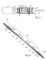
- Fig. 5 shows a partially-exploded view of an illustrative connector of the "splice can" variety for coupling together different segments of subsea cable 400.
- a connector cone 502 is placed over the end of each segment and secured to the subsea cable 400, preferably by mechanical attachment to the galvanized steel wires 300.
- the connector cones 502 provide room to spread and route the optical fibers from the hermetically sealed conduits 100 and the floodable conduits 200.
- the optical fibers may be routed via feedthroughs in pressure plates 504, which feedthroughs are then sealed before being mounted to the connector cones 502. On the pressure-controlled side of the pressure plates 504, the optical fibers are labeled 508.
- Frame rails 506 attach the pressure plates 504 together and support a connection module assembly 510 that interconnects the appropriate optical fibers 508.
- connection module assembly 510 that interconnects the appropriate optical fibers 508.
- interconnections may be performed using splicing, passive couplers, amplifiers, and/or active multiplexers.
- a housing 514 attaches to the pressure plates 504, forming a hermetically sealed canister that shields the optical fibers 508 and connection module assembly 510 from exposure to pressure or water.
- the connector cones 502 are not sealed, and consequently they permit flooding of interiors. Vents 518 may be provided to facilitate such flooding.
- the floodable conduits 200 are connected to the space inside the connector cones 502 so that the interiors are fluidly coupled to the exterior of the subsea cable 400 via these spaces.
- Fig. 6 shows a simplified communication architecture schematic, to illustrate how the interconnection of optical fibers from the hermetically sealed conduits and the floodable conduits might be performed.
- Fig. 6 shows a segment 602 of subsea cable 400 coupled by connectors 604 to its neighboring segments 606. Spaced along the length of segment 602 (and neighboring segments 606) are geophysical survey energy sensors 608. Each of these sensors 608 is coupled (as represented by dots 610) to an associated fiber 612 in a floodable conduit. At the connectors 604, each of the floodable conduit fibers 612 is coupled (as represented by dots 614) to a fiber in a hermetically sealed conduit 616.
- the connectors 604 further provide coupling between corresponding fibers in the hermetically sealed conduit of segment 602 and its neighboring segments 606.
- the segmented subsea cables may be assembled with sensors of geophysical energy (e.g., seismic, electromagnetic) and deployed in a body of water as spatially-distributed on-bottom cables.
- the deployed cables have at least one floodable optical fiber conduit with an interior in fluid communication with the body of water.
- the cables are coupled at one end to an interface that supplies optical interrogation signals to the optical fibers in the backbone, i.e., in the hermetically sealed conduits.
- the connection module assemblies cooperatively distribute the interrogation signals to the sensors and return the modulated measurement signals from the sensors to the interface, where they may be captured in digital form by a measurement data acquisition system and stored for later processing.
- the optical signals are each communicated via at least one tight buffered optical fiber along the floodable optical fiber conduit, and between the interface and the connection module assemblies, the optical signals are each transported over at least one protected optical fiber in a hermetically sealed optical fiber conduit.
- the tight buffered optical fiber has a length of no more than 2 km, though lengths as short as 5 m are also contemplated, and may have a thermoplastic elastomer or a thermoplastic fluoropolymer as a conformal buffer layer material.
- the on-bottom cables may be deployed in water bodies having depths in excess of 500 m, and are expected to by employed periodically over a period of at least ten years for, e.g., PRM operations.
- PRM operations may involve seismic shots to generate seismic waves or controlled source electromagnetic (CSEM) transmissions to generate electromagnetic fields, or such operations may be entirely passive, monitoring sensor responses to background sources of such waves and fields.
- the sensor signals are processed to map subsurface distributions of fluid and rock properties and to track changes to such distributions over time, e.g., as hydrocarbons are produced from subsurface reservoirs.
- the processing may further produce geophysical data in intermediate processing stages such as re-sampled and stacked traces, migrated and filtered data volumes, and imaged subvolumes.
- geophysical data in intermediate processing stages such as re-sampled and stacked traces, migrated and filtered data volumes, and imaged subvolumes.
- Each of these, including the raw acquired data and the final maps of subsurface property distributions, can be packaged as a geophysical data product and recorded on a tangible, nonvolatile computer readable storage medium suitable for importing the geophysical data product onshore.
- Such geophysical data products can be further subjected to geophysical analysis and interpretation, e.g., to develop and optimize reservoir production strategies.
- a geophysical data product may be produced.
- the geophysical data product may include seismic data communicated as signals via a tight buffered optical fiber along a floodable optical fiber conduit which may be stored on a non-transitory, tangible computer-readable medium.
- the geophysical data product may be produced offshore (i.e. by equipment on a vessel) or onshore (i.e. at a facility on land) either within the United States or in another country. If the geophysical data product is produced offshore or in another country, it may be imported onshore to a facility in the United States. Once onshore in the United States, geophysical analysis, including further data processing, may be performed on the geophysical data product.
Landscapes
- Physics & Mathematics (AREA)
- General Physics & Mathematics (AREA)
- Optics & Photonics (AREA)
- Engineering & Computer Science (AREA)
- Remote Sensing (AREA)
- Life Sciences & Earth Sciences (AREA)
- Geophysics (AREA)
- Electromagnetism (AREA)
- Environmental & Geological Engineering (AREA)
- Geology (AREA)
- General Life Sciences & Earth Sciences (AREA)
- Acoustics & Sound (AREA)
- Plasma & Fusion (AREA)
- Light Guides In General And Applications Therefor (AREA)
- Communication Cables (AREA)
- Mechanical Coupling Of Light Guides (AREA)
- Insulated Conductors (AREA)
- Computer Networks & Wireless Communication (AREA)
- Signal Processing (AREA)
Applications Claiming Priority (2)
| Application Number | Priority Date | Filing Date | Title |
|---|---|---|---|
| US201461941389P | 2014-02-18 | 2014-02-18 | |
| US14/452,211 US10175437B2 (en) | 2014-02-18 | 2014-08-05 | Subsea cable having floodable optical fiber conduit |
Publications (2)
| Publication Number | Publication Date |
|---|---|
| EP2908162A1 true EP2908162A1 (de) | 2015-08-19 |
| EP2908162B1 EP2908162B1 (de) | 2021-09-29 |
Family
ID=52465310
Family Applications (1)
| Application Number | Title | Priority Date | Filing Date |
|---|---|---|---|
| EP15155025.8A Active EP2908162B1 (de) | 2014-02-18 | 2015-02-13 | Unterwasserkabel mit flutbarer faseroptischer Leitung |
Country Status (5)
| Country | Link |
|---|---|
| US (1) | US10175437B2 (de) |
| EP (1) | EP2908162B1 (de) |
| CN (1) | CN104849818B (de) |
| BR (1) | BR102015002772B1 (de) |
| MX (1) | MX355188B (de) |
Cited By (1)
| Publication number | Priority date | Publication date | Assignee | Title |
|---|---|---|---|---|
| EP3002613A1 (de) * | 2014-10-03 | 2016-04-06 | PGS Geophysical AS | Flutbare optische vorrichtung, verfahren und systeme |
Families Citing this family (13)
| Publication number | Priority date | Publication date | Assignee | Title |
|---|---|---|---|---|
| WO2013188973A1 (en) * | 2012-06-18 | 2013-12-27 | Universite Laval | Optogenetic probe |
| US9442263B1 (en) * | 2014-08-08 | 2016-09-13 | Superior Essex International LP | Cable components formed with a thermoplastic elastomer as a nucleating agent |
| EP3034561B1 (de) * | 2014-12-19 | 2019-02-06 | NKT HV Cables GmbH | Verfahren zur Herstellung einer Hochspannungsgleichstromkabelverbindung und Hochspannungsgleichstromkabelverbindung |
| KR102342659B1 (ko) * | 2015-06-02 | 2021-12-23 | 엔케이티 에이치브이 케이블스 게엠베하 | 강성 조인트 조립체 |
| US9835816B2 (en) * | 2015-06-10 | 2017-12-05 | Telect, Inc. | Fiber blocking kits |
| US9823433B2 (en) | 2015-08-07 | 2017-11-21 | Pgs Geophysical As | Staggered optical fiber splices |
| US10133017B2 (en) | 2015-08-07 | 2018-11-20 | Pgs Geophysical As | Vented optical tube |
| US9823416B2 (en) | 2015-08-07 | 2017-11-21 | Pgs Geophysical As | Tube reattachment |
| EP3163013B1 (de) * | 2015-10-30 | 2018-09-19 | Siemens Aktiengesellschaft | Unterseekommunikationsadapter |
| US10215939B1 (en) * | 2017-08-25 | 2019-02-26 | Schlumberger Technology Corporation | Fiber-optic strength member components for use in outer strength member layers |
| US20200152354A1 (en) * | 2018-11-14 | 2020-05-14 | Minnesota Wire | Integrated circuits in cable |
| NO345360B1 (en) * | 2018-12-04 | 2020-12-21 | Aker Solutions As | Power umbilical with impact protection |
| CN117012446A (zh) * | 2023-05-10 | 2023-11-07 | 中辰电缆(江西)有限公司 | 一种防腐钢芯电缆 |
Citations (4)
| Publication number | Priority date | Publication date | Assignee | Title |
|---|---|---|---|---|
| GB2051398A (en) * | 1979-04-24 | 1981-01-14 | Nippon Telegraph & Telephone | An optical fiber submarine cable |
| EP2204681A1 (de) * | 2008-12-30 | 2010-07-07 | Draka Comteq B.V. | Faseroptisches Kabel perforiertem Wasserblockierelement |
| EP2520962A1 (de) * | 2011-05-03 | 2012-11-07 | Sehf-Korea Co., Ltd. | Elektrisch hybrides Glasfaserkabel |
| EP2594966A2 (de) * | 2011-11-21 | 2013-05-22 | PGS Geophysical AS | Elektromagnetisches Sensorkabel und elektrische Konfiguration dafür |
Family Cites Families (27)
| Publication number | Priority date | Publication date | Assignee | Title |
|---|---|---|---|---|
| JPS582804A (ja) * | 1981-06-29 | 1983-01-08 | Nippon Telegr & Teleph Corp <Ntt> | 海底光フアイバケ−ブル伝送路 |
| US4770494A (en) * | 1986-02-12 | 1988-09-13 | American Telephone & Telegraph Company, At&T Bell Laboratories | Low-loss silica optical waveguides |
| JPH08234067A (ja) * | 1995-02-27 | 1996-09-13 | Sumitomo Electric Ind Ltd | 光ファイバケーブル |
| US6314056B1 (en) | 1998-01-23 | 2001-11-06 | Petroleum Geo-Services | Fiber optic sensor system and method |
| US6269198B1 (en) * | 1999-10-29 | 2001-07-31 | Litton Systems, Inc. | Acoustic sensing system for downhole seismic applications utilizing an array of fiber optic sensors |
| US6289158B1 (en) * | 1999-11-18 | 2001-09-11 | Lucent Technologies Inc. | Coated optical fiber with enhanced delamination resistance and thermally enhanced strippability |
| US20030011878A1 (en) | 2001-07-11 | 2003-01-16 | Maas Steven J. | Remote pumping of optical amplifier system and method |
| US6606186B2 (en) | 2001-07-25 | 2003-08-12 | Pgs Americas, Inc. | Dynamic fiber optic sensor signal processing scheme |
| US6796821B2 (en) * | 2002-06-06 | 2004-09-28 | Ocean Design, Inc. | Field installable cable termination assembly |
| US7222534B2 (en) | 2005-03-31 | 2007-05-29 | Pgs Americas, Inc. | Optical accelerometer, optical inclinometer and seismic sensor system using such accelerometer and inclinometer |
| US7366055B2 (en) * | 2006-05-05 | 2008-04-29 | Optoplan As | Ocean bottom seismic sensing system |
| US7602191B2 (en) * | 2007-06-29 | 2009-10-13 | Pgs Geophysical As | Cable-type electromagnetic receiver system for subsurface exploration |
| US20110096624A1 (en) * | 2009-10-26 | 2011-04-28 | Harini Varadarajan | Sensing Technique for Seismic Exploration |
| EP3319091B1 (de) * | 2009-10-30 | 2022-01-05 | Aker Solutions AS | Deh-huckepackkabel |
| US8645071B2 (en) | 2009-12-23 | 2014-02-04 | Pgs Geophysical As | Direct velocity seismic sensing |
| US8990022B2 (en) | 2009-12-23 | 2015-03-24 | Pgs Geophysical As | Direct velocity seismic sensing |
| GB2488841B (en) * | 2011-03-11 | 2014-09-10 | Tgs Geophysical Company Uk Ltd | Sensor array |
| US20120250457A1 (en) | 2011-03-28 | 2012-10-04 | Pgs Americas, Inc. | Systems and methods for wireless communication in a geophysical survey streamer |
| US8388235B1 (en) * | 2011-07-24 | 2013-03-05 | Northrop Grumman Systems Corporation | Modular, optical, wet-mate connector |
| US9459363B2 (en) | 2012-12-06 | 2016-10-04 | Pgs Geophysical As | Method and system of performing geophysical surveys with autonomous underwater vehicles |
| BR112015017683A2 (pt) * | 2013-03-26 | 2017-07-11 | Afl Telecommunications Llc | alojamento de emenda de alta pressão |
| US9273816B2 (en) * | 2014-06-12 | 2016-03-01 | Verizon Patent And Licensing Inc. | Compressible device for freeze mitigation |
| US9746633B2 (en) * | 2014-10-03 | 2017-08-29 | Pgs Geophysical As | Clamp and bending strain relief apparatus and methods |
| US10101481B2 (en) * | 2014-10-03 | 2018-10-16 | Pgs Geophysical As | Floodable optical apparatus, methods and systems |
| US9823433B2 (en) * | 2015-08-07 | 2017-11-21 | Pgs Geophysical As | Staggered optical fiber splices |
| US10133017B2 (en) * | 2015-08-07 | 2018-11-20 | Pgs Geophysical As | Vented optical tube |
| US9823416B2 (en) * | 2015-08-07 | 2017-11-21 | Pgs Geophysical As | Tube reattachment |
-
2014
- 2014-08-05 US US14/452,211 patent/US10175437B2/en active Active
-
2015
- 2015-02-09 BR BR102015002772-9A patent/BR102015002772B1/pt active IP Right Grant
- 2015-02-13 EP EP15155025.8A patent/EP2908162B1/de active Active
- 2015-02-17 MX MX2015002126A patent/MX355188B/es active IP Right Grant
- 2015-02-17 CN CN201510085104.1A patent/CN104849818B/zh active Active
Patent Citations (4)
| Publication number | Priority date | Publication date | Assignee | Title |
|---|---|---|---|---|
| GB2051398A (en) * | 1979-04-24 | 1981-01-14 | Nippon Telegraph & Telephone | An optical fiber submarine cable |
| EP2204681A1 (de) * | 2008-12-30 | 2010-07-07 | Draka Comteq B.V. | Faseroptisches Kabel perforiertem Wasserblockierelement |
| EP2520962A1 (de) * | 2011-05-03 | 2012-11-07 | Sehf-Korea Co., Ltd. | Elektrisch hybrides Glasfaserkabel |
| EP2594966A2 (de) * | 2011-11-21 | 2013-05-22 | PGS Geophysical AS | Elektromagnetisches Sensorkabel und elektrische Konfiguration dafür |
Non-Patent Citations (1)
| Title |
|---|
| J.L. BAUCOM, R.S. WAGMAN, C. M. QUINN: "Ice in Stranded Loose Tube and Single-Tube Fiber Optic Cables", IWCS, 174 MAIN STREET EATONTOWN NJ 07724 USA, vol. 52, 2003, XP040424847 * |
Cited By (2)
| Publication number | Priority date | Publication date | Assignee | Title |
|---|---|---|---|---|
| EP3002613A1 (de) * | 2014-10-03 | 2016-04-06 | PGS Geophysical AS | Flutbare optische vorrichtung, verfahren und systeme |
| US10101481B2 (en) | 2014-10-03 | 2018-10-16 | Pgs Geophysical As | Floodable optical apparatus, methods and systems |
Also Published As
| Publication number | Publication date |
|---|---|
| BR102015002772B1 (pt) | 2021-08-31 |
| EP2908162B1 (de) | 2021-09-29 |
| CN104849818B (zh) | 2020-06-16 |
| MX2015002126A (es) | 2015-08-17 |
| US20150234143A1 (en) | 2015-08-20 |
| BR102015002772A2 (pt) | 2016-02-10 |
| MX355188B (es) | 2018-04-09 |
| CN104849818A (zh) | 2015-08-19 |
| US10175437B2 (en) | 2019-01-08 |
Similar Documents
| Publication | Publication Date | Title |
|---|---|---|
| EP2908162B1 (de) | Unterwasserkabel mit flutbarer faseroptischer Leitung | |
| AU2015230692B2 (en) | Floodable optical apparatus, methods and systems | |
| US4952012A (en) | Electro-opto-mechanical cable for fiber optic transmission systems | |
| US9042202B2 (en) | Split-element optical hydrophone | |
| FR2864202A1 (fr) | Dispositif tubulaire instrumente pour le transport d'un fluide sous pression | |
| CN109765561B (zh) | 光纤水听器阵段结构和光纤水听器阵列结构 | |
| AU2020205308A1 (en) | Multisensing optical fiber cable | |
| CN211061047U (zh) | 一种垂直吊放型矢量水听器阵列及潜标系统 | |
| EP3002842B1 (de) | Klemm- und biegezugentlastungsvorrichtung und -verfahren | |
| US9823433B2 (en) | Staggered optical fiber splices | |
| CN101382625A (zh) | 多束多芯耐高温高压光缆 | |
| AU2015200537B2 (en) | Subsea cable having floodable optical fiber conduit | |
| US10711591B2 (en) | Sensing umbilical | |
| EP2261615A2 (de) | Seismischer Streamer | |
| WO2016021659A1 (ja) | 光ファイバペネトレーション | |
| JP2001324358A (ja) | 光ファイバセンサ | |
| US9823416B2 (en) | Tube reattachment | |
| US10133017B2 (en) | Vented optical tube | |
| CN116487104A (zh) | 海缆监测系统及其生产方法 | |
| CN2525544Y (zh) | 高强钢丝铠装海底光缆 | |
| CN203673884U (zh) | 一种脐带缆 | |
| CN215930814U (zh) | 一种分布式光纤曲率监测海缆 | |
| Waterworth et al. | Submarine communications cable for deep-sea application | |
| JPH0262506A (ja) | 海底光ケーブル |
Legal Events
| Date | Code | Title | Description |
|---|---|---|---|
| PUAI | Public reference made under article 153(3) epc to a published international application that has entered the european phase |
Free format text: ORIGINAL CODE: 0009012 |
|
| AK | Designated contracting states |
Kind code of ref document: A1 Designated state(s): AL AT BE BG CH CY CZ DE DK EE ES FI FR GB GR HR HU IE IS IT LI LT LU LV MC MK MT NL NO PL PT RO RS SE SI SK SM TR |
|
| AX | Request for extension of the european patent |
Extension state: BA ME |
|
| 17P | Request for examination filed |
Effective date: 20160218 |
|
| RBV | Designated contracting states (corrected) |
Designated state(s): AL AT BE BG CH CY CZ DE DK EE ES FI FR GB GR HR HU IE IS IT LI LT LU LV MC MK MT NL NO PL PT RO RS SE SI SK SM TR |
|
| STAA | Information on the status of an ep patent application or granted ep patent |
Free format text: STATUS: EXAMINATION IS IN PROGRESS |
|
| 17Q | First examination report despatched |
Effective date: 20180912 |
|
| RAP1 | Party data changed (applicant data changed or rights of an application transferred) |
Owner name: GEOSPACE TECHNOLOGIES CORPORATION |
|
| GRAP | Despatch of communication of intention to grant a patent |
Free format text: ORIGINAL CODE: EPIDOSNIGR1 |
|
| STAA | Information on the status of an ep patent application or granted ep patent |
Free format text: STATUS: GRANT OF PATENT IS INTENDED |
|
| INTG | Intention to grant announced |
Effective date: 20210429 |
|
| GRAS | Grant fee paid |
Free format text: ORIGINAL CODE: EPIDOSNIGR3 |
|
| GRAA | (expected) grant |
Free format text: ORIGINAL CODE: 0009210 |
|
| STAA | Information on the status of an ep patent application or granted ep patent |
Free format text: STATUS: THE PATENT HAS BEEN GRANTED |
|
| AK | Designated contracting states |
Kind code of ref document: B1 Designated state(s): AL AT BE BG CH CY CZ DE DK EE ES FI FR GB GR HR HU IE IS IT LI LT LU LV MC MK MT NL NO PL PT RO RS SE SI SK SM TR |
|
| REG | Reference to a national code |
Ref country code: GB Ref legal event code: FG4D |
|
| REG | Reference to a national code |
Ref country code: CH Ref legal event code: EP Ref country code: AT Ref legal event code: REF Ref document number: 1434697 Country of ref document: AT Kind code of ref document: T Effective date: 20211015 |
|
| REG | Reference to a national code |
Ref country code: DE Ref legal event code: R096 Ref document number: 602015073641 Country of ref document: DE |
|
| REG | Reference to a national code |
Ref country code: IE Ref legal event code: FG4D |
|
| REG | Reference to a national code |
Ref country code: LT Ref legal event code: MG9D |
|
| REG | Reference to a national code |
Ref country code: NO Ref legal event code: T2 Effective date: 20210929 |
|
| PG25 | Lapsed in a contracting state [announced via postgrant information from national office to epo] |
Ref country code: LT Free format text: LAPSE BECAUSE OF FAILURE TO SUBMIT A TRANSLATION OF THE DESCRIPTION OR TO PAY THE FEE WITHIN THE PRESCRIBED TIME-LIMIT Effective date: 20210929 Ref country code: BG Free format text: LAPSE BECAUSE OF FAILURE TO SUBMIT A TRANSLATION OF THE DESCRIPTION OR TO PAY THE FEE WITHIN THE PRESCRIBED TIME-LIMIT Effective date: 20211229 Ref country code: FI Free format text: LAPSE BECAUSE OF FAILURE TO SUBMIT A TRANSLATION OF THE DESCRIPTION OR TO PAY THE FEE WITHIN THE PRESCRIBED TIME-LIMIT Effective date: 20210929 Ref country code: SE Free format text: LAPSE BECAUSE OF FAILURE TO SUBMIT A TRANSLATION OF THE DESCRIPTION OR TO PAY THE FEE WITHIN THE PRESCRIBED TIME-LIMIT Effective date: 20210929 Ref country code: RS Free format text: LAPSE BECAUSE OF FAILURE TO SUBMIT A TRANSLATION OF THE DESCRIPTION OR TO PAY THE FEE WITHIN THE PRESCRIBED TIME-LIMIT Effective date: 20210929 Ref country code: HR Free format text: LAPSE BECAUSE OF FAILURE TO SUBMIT A TRANSLATION OF THE DESCRIPTION OR TO PAY THE FEE WITHIN THE PRESCRIBED TIME-LIMIT Effective date: 20210929 |
|
| REG | Reference to a national code |
Ref country code: NL Ref legal event code: MP Effective date: 20210929 |
|
| REG | Reference to a national code |
Ref country code: AT Ref legal event code: MK05 Ref document number: 1434697 Country of ref document: AT Kind code of ref document: T Effective date: 20210929 |
|
| PG25 | Lapsed in a contracting state [announced via postgrant information from national office to epo] |
Ref country code: LV Free format text: LAPSE BECAUSE OF FAILURE TO SUBMIT A TRANSLATION OF THE DESCRIPTION OR TO PAY THE FEE WITHIN THE PRESCRIBED TIME-LIMIT Effective date: 20210929 Ref country code: GR Free format text: LAPSE BECAUSE OF FAILURE TO SUBMIT A TRANSLATION OF THE DESCRIPTION OR TO PAY THE FEE WITHIN THE PRESCRIBED TIME-LIMIT Effective date: 20211230 |
|
| PG25 | Lapsed in a contracting state [announced via postgrant information from national office to epo] |
Ref country code: AT Free format text: LAPSE BECAUSE OF FAILURE TO SUBMIT A TRANSLATION OF THE DESCRIPTION OR TO PAY THE FEE WITHIN THE PRESCRIBED TIME-LIMIT Effective date: 20210929 |
|
| PG25 | Lapsed in a contracting state [announced via postgrant information from national office to epo] |
Ref country code: IS Free format text: LAPSE BECAUSE OF FAILURE TO SUBMIT A TRANSLATION OF THE DESCRIPTION OR TO PAY THE FEE WITHIN THE PRESCRIBED TIME-LIMIT Effective date: 20220129 Ref country code: SK Free format text: LAPSE BECAUSE OF FAILURE TO SUBMIT A TRANSLATION OF THE DESCRIPTION OR TO PAY THE FEE WITHIN THE PRESCRIBED TIME-LIMIT Effective date: 20210929 Ref country code: RO Free format text: LAPSE BECAUSE OF FAILURE TO SUBMIT A TRANSLATION OF THE DESCRIPTION OR TO PAY THE FEE WITHIN THE PRESCRIBED TIME-LIMIT Effective date: 20210929 Ref country code: PT Free format text: LAPSE BECAUSE OF FAILURE TO SUBMIT A TRANSLATION OF THE DESCRIPTION OR TO PAY THE FEE WITHIN THE PRESCRIBED TIME-LIMIT Effective date: 20220131 Ref country code: PL Free format text: LAPSE BECAUSE OF FAILURE TO SUBMIT A TRANSLATION OF THE DESCRIPTION OR TO PAY THE FEE WITHIN THE PRESCRIBED TIME-LIMIT Effective date: 20210929 Ref country code: NL Free format text: LAPSE BECAUSE OF FAILURE TO SUBMIT A TRANSLATION OF THE DESCRIPTION OR TO PAY THE FEE WITHIN THE PRESCRIBED TIME-LIMIT Effective date: 20210929 Ref country code: ES Free format text: LAPSE BECAUSE OF FAILURE TO SUBMIT A TRANSLATION OF THE DESCRIPTION OR TO PAY THE FEE WITHIN THE PRESCRIBED TIME-LIMIT Effective date: 20210929 Ref country code: EE Free format text: LAPSE BECAUSE OF FAILURE TO SUBMIT A TRANSLATION OF THE DESCRIPTION OR TO PAY THE FEE WITHIN THE PRESCRIBED TIME-LIMIT Effective date: 20210929 Ref country code: CZ Free format text: LAPSE BECAUSE OF FAILURE TO SUBMIT A TRANSLATION OF THE DESCRIPTION OR TO PAY THE FEE WITHIN THE PRESCRIBED TIME-LIMIT Effective date: 20210929 Ref country code: AL Free format text: LAPSE BECAUSE OF FAILURE TO SUBMIT A TRANSLATION OF THE DESCRIPTION OR TO PAY THE FEE WITHIN THE PRESCRIBED TIME-LIMIT Effective date: 20210929 |
|
| REG | Reference to a national code |
Ref country code: DE Ref legal event code: R097 Ref document number: 602015073641 Country of ref document: DE |
|
| PG25 | Lapsed in a contracting state [announced via postgrant information from national office to epo] |
Ref country code: DK Free format text: LAPSE BECAUSE OF FAILURE TO SUBMIT A TRANSLATION OF THE DESCRIPTION OR TO PAY THE FEE WITHIN THE PRESCRIBED TIME-LIMIT Effective date: 20210929 |
|
| PLBE | No opposition filed within time limit |
Free format text: ORIGINAL CODE: 0009261 |
|
| STAA | Information on the status of an ep patent application or granted ep patent |
Free format text: STATUS: NO OPPOSITION FILED WITHIN TIME LIMIT |
|
| 26N | No opposition filed |
Effective date: 20220630 |
|
| PG25 | Lapsed in a contracting state [announced via postgrant information from national office to epo] |
Ref country code: MC Free format text: LAPSE BECAUSE OF FAILURE TO SUBMIT A TRANSLATION OF THE DESCRIPTION OR TO PAY THE FEE WITHIN THE PRESCRIBED TIME-LIMIT Effective date: 20210929 |
|
| REG | Reference to a national code |
Ref country code: CH Ref legal event code: PL |
|
| REG | Reference to a national code |
Ref country code: BE Ref legal event code: MM Effective date: 20220228 |
|
| PG25 | Lapsed in a contracting state [announced via postgrant information from national office to epo] |
Ref country code: LU Free format text: LAPSE BECAUSE OF NON-PAYMENT OF DUE FEES Effective date: 20220213 |
|
| PGFP | Annual fee paid to national office [announced via postgrant information from national office to epo] |
Ref country code: DE Payment date: 20220731 Year of fee payment: 8 |
|
| PG25 | Lapsed in a contracting state [announced via postgrant information from national office to epo] |
Ref country code: SI Free format text: LAPSE BECAUSE OF FAILURE TO SUBMIT A TRANSLATION OF THE DESCRIPTION OR TO PAY THE FEE WITHIN THE PRESCRIBED TIME-LIMIT Effective date: 20210929 |
|
| PG25 | Lapsed in a contracting state [announced via postgrant information from national office to epo] |
Ref country code: LI Free format text: LAPSE BECAUSE OF NON-PAYMENT OF DUE FEES Effective date: 20220228 Ref country code: IT Free format text: LAPSE BECAUSE OF FAILURE TO SUBMIT A TRANSLATION OF THE DESCRIPTION OR TO PAY THE FEE WITHIN THE PRESCRIBED TIME-LIMIT Effective date: 20210929 Ref country code: IE Free format text: LAPSE BECAUSE OF NON-PAYMENT OF DUE FEES Effective date: 20220213 Ref country code: CH Free format text: LAPSE BECAUSE OF NON-PAYMENT OF DUE FEES Effective date: 20220228 |
|
| PG25 | Lapsed in a contracting state [announced via postgrant information from national office to epo] |
Ref country code: BE Free format text: LAPSE BECAUSE OF NON-PAYMENT OF DUE FEES Effective date: 20220228 |
|
| P01 | Opt-out of the competence of the unified patent court (upc) registered |
Effective date: 20230518 |
|
| REG | Reference to a national code |
Ref country code: DE Ref legal event code: R119 Ref document number: 602015073641 Country of ref document: DE |
|
| PG25 | Lapsed in a contracting state [announced via postgrant information from national office to epo] |
Ref country code: DE Free format text: LAPSE BECAUSE OF NON-PAYMENT OF DUE FEES Effective date: 20230901 |
|
| PG25 | Lapsed in a contracting state [announced via postgrant information from national office to epo] |
Ref country code: HU Free format text: LAPSE BECAUSE OF FAILURE TO SUBMIT A TRANSLATION OF THE DESCRIPTION OR TO PAY THE FEE WITHIN THE PRESCRIBED TIME-LIMIT; INVALID AB INITIO Effective date: 20150213 |
|
| PG25 | Lapsed in a contracting state [announced via postgrant information from national office to epo] |
Ref country code: SM Free format text: LAPSE BECAUSE OF FAILURE TO SUBMIT A TRANSLATION OF THE DESCRIPTION OR TO PAY THE FEE WITHIN THE PRESCRIBED TIME-LIMIT Effective date: 20210929 Ref country code: MK Free format text: LAPSE BECAUSE OF FAILURE TO SUBMIT A TRANSLATION OF THE DESCRIPTION OR TO PAY THE FEE WITHIN THE PRESCRIBED TIME-LIMIT Effective date: 20210929 Ref country code: CY Free format text: LAPSE BECAUSE OF FAILURE TO SUBMIT A TRANSLATION OF THE DESCRIPTION OR TO PAY THE FEE WITHIN THE PRESCRIBED TIME-LIMIT Effective date: 20210929 |
|
| PG25 | Lapsed in a contracting state [announced via postgrant information from national office to epo] |
Ref country code: MT Free format text: LAPSE BECAUSE OF FAILURE TO SUBMIT A TRANSLATION OF THE DESCRIPTION OR TO PAY THE FEE WITHIN THE PRESCRIBED TIME-LIMIT Effective date: 20210929 |
|
| PG25 | Lapsed in a contracting state [announced via postgrant information from national office to epo] |
Ref country code: TR Free format text: LAPSE BECAUSE OF FAILURE TO SUBMIT A TRANSLATION OF THE DESCRIPTION OR TO PAY THE FEE WITHIN THE PRESCRIBED TIME-LIMIT Effective date: 20210929 |
|
| PGFP | Annual fee paid to national office [announced via postgrant information from national office to epo] |
Ref country code: FR Payment date: 20251208 Year of fee payment: 12 |
|
| PGFP | Annual fee paid to national office [announced via postgrant information from national office to epo] |
Ref country code: GB Payment date: 20260106 Year of fee payment: 12 |
|
| PGFP | Annual fee paid to national office [announced via postgrant information from national office to epo] |
Ref country code: NO Payment date: 20260211 Year of fee payment: 12 |