EP2908325A1 - Elektrischer Schalter mit einem Aktuator - Google Patents
Elektrischer Schalter mit einem Aktuator Download PDFInfo
- Publication number
- EP2908325A1 EP2908325A1 EP15154455.8A EP15154455A EP2908325A1 EP 2908325 A1 EP2908325 A1 EP 2908325A1 EP 15154455 A EP15154455 A EP 15154455A EP 2908325 A1 EP2908325 A1 EP 2908325A1
- Authority
- EP
- European Patent Office
- Prior art keywords
- actuating lever
- actuating
- housing
- plunger
- switch
- Prior art date
- Legal status (The legal status is an assumption and is not a legal conclusion. Google has not performed a legal analysis and makes no representation as to the accuracy of the status listed.)
- Granted
Links
- 239000000463 material Substances 0.000 claims description 7
- 230000003313 weakening effect Effects 0.000 claims description 5
- 239000002184 metal Substances 0.000 claims description 3
- 238000003780 insertion Methods 0.000 claims description 2
- 230000037431 insertion Effects 0.000 claims description 2
- 239000012858 resilient material Substances 0.000 claims description 2
- 230000000254 damaging effect Effects 0.000 abstract description 3
- 230000000284 resting effect Effects 0.000 description 2
- 238000010276 construction Methods 0.000 description 1
- 238000012986 modification Methods 0.000 description 1
- 230000004048 modification Effects 0.000 description 1
- 230000000750 progressive effect Effects 0.000 description 1
- 239000007787 solid Substances 0.000 description 1
Images
Classifications
-
- H—ELECTRICITY
- H01—ELECTRIC ELEMENTS
- H01H—ELECTRIC SWITCHES; RELAYS; SELECTORS; EMERGENCY PROTECTIVE DEVICES
- H01H3/00—Mechanisms for operating contacts
- H01H3/02—Operating parts, i.e. for operating driving mechanism by a mechanical force external to the switch
- H01H3/04—Levers
-
- H—ELECTRICITY
- H01—ELECTRIC ELEMENTS
- H01H—ELECTRIC SWITCHES; RELAYS; SELECTORS; EMERGENCY PROTECTIVE DEVICES
- H01H13/00—Switches having rectilinearly-movable operating part or parts adapted for pushing or pulling in one direction only, e.g. push-button switch
- H01H13/02—Details
- H01H13/12—Movable parts; Contacts mounted thereon
- H01H13/14—Operating parts, e.g. push-button
- H01H13/18—Operating parts, e.g. push-button adapted for actuation at a limit or other predetermined position in the path of a body, the relative movement of switch and body being primarily for a purpose other than the actuation of the switch, e.g. door switch, limit switch, floor-levelling switch of a lift
- H01H13/186—Operating parts, e.g. push-button adapted for actuation at a limit or other predetermined position in the path of a body, the relative movement of switch and body being primarily for a purpose other than the actuation of the switch, e.g. door switch, limit switch, floor-levelling switch of a lift wherein the pushbutton is rectilinearly actuated by a lever pivoting on the housing of the switch
-
- H—ELECTRICITY
- H01—ELECTRIC ELEMENTS
- H01H—ELECTRIC SWITCHES; RELAYS; SELECTORS; EMERGENCY PROTECTIVE DEVICES
- H01H1/00—Contacts
- H01H1/12—Contacts characterised by the manner in which co-operating contacts engage
- H01H1/14—Contacts characterised by the manner in which co-operating contacts engage by abutting
- H01H1/24—Contacts characterised by the manner in which co-operating contacts engage by abutting with resilient mounting
- H01H1/26—Contacts characterised by the manner in which co-operating contacts engage by abutting with resilient mounting with spring blade support
-
- H—ELECTRICITY
- H01—ELECTRIC ELEMENTS
- H01H—ELECTRIC SWITCHES; RELAYS; SELECTORS; EMERGENCY PROTECTIVE DEVICES
- H01H13/00—Switches having rectilinearly-movable operating part or parts adapted for pushing or pulling in one direction only, e.g. push-button switch
- H01H13/02—Details
- H01H13/26—Snap-action arrangements depending upon deformation of elastic members
- H01H13/36—Snap-action arrangements depending upon deformation of elastic members using flexing of blade springs
Definitions
- This invention relates to an electrical switch and in particular, to an electrical switch having an actuator.
- the invention relates to an electric switch with a housing comprising an upper surface, an actuating plunger which passed through the housing and an actuating lever mounted on and pivotable or otherwise movable with respect to the housing.
- the actuating lever forms an additional actuator.
- a force for triggering the switch is therefore to be applied, not directly to the actuating plunger, but to the actuating lever.
- the switching force is transferred to the actuating plunger with the aid of the actuating lever.
- Such switches and micro-switches are often provided with additional actuators of this kind. They are used to enlarge the switching travel and to receive forces, which in their direction deviate from the movement direction of the actuating plunger. Lateral pushing actuations are converted into travel in direction of the axis of the actuating element. As a result the switch actuating element is stressed less, the range of possible applications is widened and the lifetime of the switch, as a rule, is increased.
- this requirement is met in that the actuating plunger is arranged in the upper surface close to a side surface of the housing, and in that an articulation for the actuating lever is formed at this side surface, wherein the actuating lever extends beyond the upper surface of the housing and in that a stop for the actuating plunger is arranged inside the housing.
- the actuating plunger is initially mounted to a side surface. To this end a stable articulation can be formed at the side surface.
- the actuating plunger is arranged close to the side surface of the housing, on which the actuating lever is mounted. The actuating lever can thus protrude freely above the upper surface of the housing with the larger piece of its extension, whilst a shorter section of its extension is formed between the articulation of the actuating lever and the point at which the actuating lever rests on the actuating plunger.
- the actuating lever to extend beyond the upper surface of the housing. This means that the free sections of the actuating lever are no longer arranged above the upper surface of the housing, but protrude freely. If a switching force is applied to this freely protruding section of the actuating lever, the actuating plunger is moved in a triggering manner with the aid of the actuating lever. Following the switching jump of the internal switching element, the actuating plunger is prevented by the stop arranged in the switch housing from moving any further. Forces of improper use are kept at a distance from the switching element by means of the stop.
- the blocked actuating plunger represents a firm contact surface for the actuating lever, which then, using this contact surface, can be moved further and in this way permits an additional over-travel. This is particularly advantageous for switching systems with a short switching stroke.
- the actuating lever is allowed to move further without the switching state of the electric switch changing in any way. If now the lever is moved yet further, the actuating lever can make contact with the upper surface of the housing.
- the upper surface thus forms a receptacle for the actuating lever thereby preventing any damage to it.
- the edge of the housing facing away from the articulation of the actuating lever between the upper surface and a side surface functions as a contact point for the actuating lever.
- the free end of the actuating lever can be bent over the edge, and in doing so the lever of the actuating lever is shortened due to the new contact point at the edge of the housing.
- the actuating lever is now able to resist the contacting forces through the application of a higher counterforce.
- the actuating lever may be inserted into a gap arranged in the housing in the area of the side surface.
- a simple but also secure positioning of the actuating lever is achieved.
- This can be reinforced, in particular, if the actuating lever comprises at least one barb in the area provided for insertion. Based on this barb the actuating lever is able to closely connect itself with the material of the housing in the area of the gap.
- the actuating lever is configured as a spring of solid but resilient material.
- the spring of the actuating lever may, for example, be constructed of metal.
- a next further development of the invention provides for the actuating lever to comprise at least one material weakening in the area facing away from the articulation with regard to the actuating plunger. Based on this material weakening the spring characteristic of the actuating lever is adjustable. By removing more material, the actuating lever's capability to yield to forces occurring in this area, is increased.
- the material weakening may, for example, be realised by providing lateral indents in the extension of the actuating lever. Due to the indents a steep progressive spring characteristic in the over-travel of the actuating lever is avoided. Solely due to the inventive configuration of the actuating lever the actuating travel for the switching operation is extended in relation to the actuating plunger. Moreover, after the switching point has been reached, an over-travel is present without any forces of improper use, which might occur, causing a damaging effect.
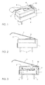
- the switch of Figure 1 comprises an approximately rectangular housing 1.
- the housing 1 has side surfaces and an upper surface 2.
- An actuating plunger 3 is arranged in the upper surface 2.
- the actuating plunger 3 is positioned close to one of the side surfaces, and in the area of this side surface an actuating lever 4 is attached to the housing 1.
- the actuating lever 4 extends above, over and beyond the upper surface 2 of the housing 1.
- the actuating lever 4 comprises indents 5, forming a narrowed and thus more flexible portion of the lever.
- Contacts 6 protrude from the underside of the switch.
- the actuating lever is a strip of resilient metal that is pre-shaped and mounted to the housing by being inserted in a gap 10 in the side of the housing. It has a bend in a portion corresponding to an edge between the said side and the upper surface of the housing. This bend creates an articulation point or hinge about which the actuating lever moves or pivots under normal operating conditions.
- the switch is shown with three contacts 6, common, upper and lower, extending through the bottom of the housing and forming a common terminal, a normally closed terminal and a normally open terminal, respectively.
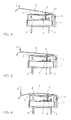
- FIG. 2 shows the actuating lever 4 resting on the actuating plunger 3. This rest position of the switch is also shown in Figure 3 .
- a spring switching element 7 arranged inside the housing 1 is supported against the upper contact 6.
- Figure 6 shows an over-stroke or possible over-travel of the actuating lever 4 due to the impact of even greater forces indicated by arrow S".
- the actuating lever 4 is nearly touching the edge 9 of the housing 1 formed by the upper surface 2 and a side wall.
- the upper surface 2 is still indented, and the actuating plunger 3 is still resting on the stop 8. If the actuating lever 4 is moved still further along arrow S" the actuating lever 4 will come to rest on the edge 9. Then the point of leverage for the actuating lever 4 will shift its position. In Figures 3 and 4 this point of leverage is the first corner of the housing adjacent to the attachment of the actuating lever.
- the actuating lever 4 In order to ensure that the actuating lever 4 is connected securely with the housing 1, the actuating lever 4 is inserted into the gap 10 of the housing 1, the actuating lever 4 additionally comprises a barb 11 to prevent accidental removal of the actuating lever 4 from the gap 10.
Landscapes
- Mechanisms For Operating Contacts (AREA)
- Rotary Switch, Piano Key Switch, And Lever Switch (AREA)
- Push-Button Switches (AREA)
- Arrangement Or Mounting Of Control Devices For Change-Speed Gearing (AREA)
Applications Claiming Priority (2)
| Application Number | Priority Date | Filing Date | Title |
|---|---|---|---|
| DE102014002104 | 2014-02-15 | ||
| DE102014006943.5A DE102014006943A1 (de) | 2014-02-15 | 2014-05-10 | Elektrischer Schalter mit einem eine obere Fläche aufweisenden Gehäuse |
Publications (2)
| Publication Number | Publication Date |
|---|---|
| EP2908325A1 true EP2908325A1 (de) | 2015-08-19 |
| EP2908325B1 EP2908325B1 (de) | 2019-06-19 |
Family
ID=52462846
Family Applications (1)
| Application Number | Title | Priority Date | Filing Date |
|---|---|---|---|
| EP15154455.8A Active EP2908325B1 (de) | 2014-02-15 | 2015-02-10 | Elektrischer Schalter mit einem Aktuator |
Country Status (5)
| Country | Link |
|---|---|
| US (1) | US9613765B2 (de) |
| EP (1) | EP2908325B1 (de) |
| JP (1) | JP6533393B2 (de) |
| CN (1) | CN104851663B (de) |
| DE (1) | DE102014006943A1 (de) |
Families Citing this family (4)
| Publication number | Priority date | Publication date | Assignee | Title |
|---|---|---|---|---|
| EP3166121B1 (de) * | 2015-11-03 | 2019-03-27 | C&K Components SAS | Elektrischer drucktastenschalter |
| JP6662537B2 (ja) * | 2016-07-22 | 2020-03-11 | アルプスアルパイン株式会社 | スイッチ装置及び該スイッチ装置の製造方法 |
| US10304643B1 (en) | 2018-02-28 | 2019-05-28 | CoActive Technologies, LLC | Single-pole, single-throw detect switch |
| JP6958863B2 (ja) | 2018-06-27 | 2021-11-02 | 矢崎総業株式会社 | 電気的接続部の劣化度合診断装置、及び、劣化度合診断方法 |
Citations (4)
| Publication number | Priority date | Publication date | Assignee | Title |
|---|---|---|---|---|
| US2743331A (en) * | 1955-01-21 | 1956-04-24 | W L Maxson Corp | Snap switch |
| GB798638A (en) * | 1955-07-26 | 1958-07-23 | W L Maxson Corp | Improvements relating to snap-action electric switches |
| EP2006868A2 (de) * | 2007-06-20 | 2008-12-24 | Alps Electric Co., Ltd. | Schaltvorrichtung mit Druckknopf und Hebel |
| WO2012090521A1 (ja) * | 2010-12-27 | 2012-07-05 | オムロン株式会社 | スイッチ |
Family Cites Families (20)
| Publication number | Priority date | Publication date | Assignee | Title |
|---|---|---|---|---|
| FR1402906A (fr) * | 1964-03-12 | 1965-06-18 | Crouzet Sa | Dispositif permettant de rendre hermétique les appareils tels que les contacteurs àaction brusque dont l'enceinte est en matière plastique |
| GB1404309A (en) * | 1971-09-09 | 1975-08-28 | Otehall Ltd | Electrical switches |
| US3755642A (en) * | 1972-05-17 | 1973-08-28 | Robertshaw Controls Co | Lever means for an electrical switch construction or the like and method of making the same |
| JPS5036066U (de) * | 1973-07-27 | 1975-04-16 | ||
| JPS5434072U (de) * | 1977-08-11 | 1979-03-06 | ||
| JPS54166590U (de) * | 1978-05-16 | 1979-11-22 | ||
| JPS57176025U (de) * | 1981-05-01 | 1982-11-06 | ||
| JPS6154119A (ja) * | 1984-08-24 | 1986-03-18 | 松下電工株式会社 | 小形スイツチ |
| DE8624712U1 (de) * | 1986-09-16 | 1994-04-14 | Doepke & Co Schaltgerätefabrik GmbH & Co KG, 26506 Norden | Hermetisch geschlossener permanentmagnetischer Auslöser für Fehlerstromschutzschalter |
| JPH01274326A (ja) * | 1988-04-25 | 1989-11-02 | Matsushita Electric Works Ltd | スイッチ |
| JPH0648714Y2 (ja) * | 1989-03-02 | 1994-12-12 | 神明電機株式会社 | マイクロスイッチ |
| DE9013310U1 (de) * | 1990-09-20 | 1990-11-29 | Burgess GmbH, 2900 Oldenburg | Elektrischer Schalter, insbesondere Kleinstschalter, mit einem Betätigungshebel |
| GB9225052D0 (en) * | 1992-11-30 | 1993-01-20 | Burgess Micro Switch Co Ltd | Electric switch |
| DE19727553A1 (de) * | 1997-04-09 | 1998-10-15 | Marquardt Gmbh | Elektrischer Schalter |
| TW551793U (en) * | 2002-11-29 | 2003-09-01 | Hon Hai Prec Ind Co Ltd | A bracket for sensors |
| JP4323363B2 (ja) * | 2004-04-01 | 2009-09-02 | アルプス電気株式会社 | スイッチ装置 |
| GB0407996D0 (en) | 2004-04-07 | 2004-05-12 | Eja Ltd | Switch mechanism with seal |
| DE202006018987U1 (de) | 2006-12-16 | 2007-03-08 | Saia-Burgess Oldenburg Gmbh & Co. Kg | Schalter, insbesondere Mikroschalter, mit einem Gehäuse und mit zumindest einem das Gehäuse durchbrechenden Schalterstößel |
| CN202796570U (zh) * | 2012-09-17 | 2013-03-13 | 宁波嘉林电子有限公司 | 同步双体微动开关 |
| CN103165317A (zh) * | 2013-03-14 | 2013-06-19 | 吴静 | 一种用于洗衣机的上盖轻触开关 |
-
2014
- 2014-05-10 DE DE102014006943.5A patent/DE102014006943A1/de not_active Withdrawn
-
2015
- 2015-02-10 EP EP15154455.8A patent/EP2908325B1/de active Active
- 2015-02-12 CN CN201510073939.5A patent/CN104851663B/zh not_active Expired - Fee Related
- 2015-02-13 JP JP2015026608A patent/JP6533393B2/ja not_active Expired - Fee Related
- 2015-02-13 US US14/622,285 patent/US9613765B2/en not_active Expired - Fee Related
Patent Citations (4)
| Publication number | Priority date | Publication date | Assignee | Title |
|---|---|---|---|---|
| US2743331A (en) * | 1955-01-21 | 1956-04-24 | W L Maxson Corp | Snap switch |
| GB798638A (en) * | 1955-07-26 | 1958-07-23 | W L Maxson Corp | Improvements relating to snap-action electric switches |
| EP2006868A2 (de) * | 2007-06-20 | 2008-12-24 | Alps Electric Co., Ltd. | Schaltvorrichtung mit Druckknopf und Hebel |
| WO2012090521A1 (ja) * | 2010-12-27 | 2012-07-05 | オムロン株式会社 | スイッチ |
Also Published As
| Publication number | Publication date |
|---|---|
| US9613765B2 (en) | 2017-04-04 |
| CN104851663A (zh) | 2015-08-19 |
| EP2908325B1 (de) | 2019-06-19 |
| US20150235783A1 (en) | 2015-08-20 |
| JP6533393B2 (ja) | 2019-06-19 |
| JP2015153756A (ja) | 2015-08-24 |
| DE102014006943A1 (de) | 2015-08-20 |
| CN104851663B (zh) | 2019-09-17 |
Similar Documents
| Publication | Publication Date | Title |
|---|---|---|
| EP2908325B1 (de) | Elektrischer Schalter mit einem Aktuator | |
| CN110199439B (zh) | 接线端子 | |
| US10211007B2 (en) | Electrical pushbutton switch | |
| EP3156806A1 (de) | Sondenstift | |
| US8766126B2 (en) | Operation switch | |
| CN107924789B (zh) | 继电器 | |
| KR102085463B1 (ko) | 스위치 장치 구조 | |
| US8188389B2 (en) | Slide switch | |
| CN101026050B (zh) | 漏电流减小的继电器 | |
| EP3018682B1 (de) | Schaltvorrichtung | |
| CN102820173B (zh) | 电接触器 | |
| US8872051B2 (en) | Control device for switches with silicone domes | |
| EP1734548A2 (de) | Schaltervorrichtung | |
| US2304400A (en) | Snap switch | |
| US2810030A (en) | Electric switches | |
| CN103681073A (zh) | 开关装置 | |
| US3539742A (en) | Electrical snap switch having stressed blade | |
| AU2018204641B2 (en) | Push-button switch | |
| CN102473535B (zh) | 用于电磁开关设备的触点装置 | |
| US9373465B1 (en) | Switch with overload release structure | |
| US7935905B2 (en) | Contact system | |
| CN103247456B (zh) | 电气的开关设备尤其断路器 | |
| JP5523961B2 (ja) | スイッチ装置及びこのスイッチ装置を用いたスイッチユニット | |
| US8143538B2 (en) | Multi-directional operating switch assembly | |
| US20130048483A1 (en) | M-blade snap action switch with optimal switch contact forces |
Legal Events
| Date | Code | Title | Description |
|---|---|---|---|
| PUAI | Public reference made under article 153(3) epc to a published international application that has entered the european phase |
Free format text: ORIGINAL CODE: 0009012 |
|
| AK | Designated contracting states |
Kind code of ref document: A1 Designated state(s): AL AT BE BG CH CY CZ DE DK EE ES FI FR GB GR HR HU IE IS IT LI LT LU LV MC MK MT NL NO PL PT RO RS SE SI SK SM TR |
|
| AX | Request for extension of the european patent |
Extension state: BA ME |
|
| 17P | Request for examination filed |
Effective date: 20160211 |
|
| RBV | Designated contracting states (corrected) |
Designated state(s): AL AT BE BG CH CY CZ DE DK EE ES FI FR GB GR HR HU IE IS IT LI LT LU LV MC MK MT NL NO PL PT RO RS SE SI SK SM TR |
|
| STAA | Information on the status of an ep patent application or granted ep patent |
Free format text: STATUS: EXAMINATION IS IN PROGRESS |
|
| 17Q | First examination report despatched |
Effective date: 20180806 |
|
| GRAP | Despatch of communication of intention to grant a patent |
Free format text: ORIGINAL CODE: EPIDOSNIGR1 |
|
| STAA | Information on the status of an ep patent application or granted ep patent |
Free format text: STATUS: GRANT OF PATENT IS INTENDED |
|
| RIC1 | Information provided on ipc code assigned before grant |
Ipc: H01H 3/04 20060101ALI20181218BHEP Ipc: H01H 13/18 20060101AFI20181218BHEP Ipc: H01H 1/26 20060101ALI20181218BHEP |
|
| INTG | Intention to grant announced |
Effective date: 20190111 |
|
| RIN1 | Information on inventor provided before grant (corrected) |
Inventor name: KOEPSELL, MARTIN |
|
| GRAS | Grant fee paid |
Free format text: ORIGINAL CODE: EPIDOSNIGR3 |
|
| GRAA | (expected) grant |
Free format text: ORIGINAL CODE: 0009210 |
|
| STAA | Information on the status of an ep patent application or granted ep patent |
Free format text: STATUS: THE PATENT HAS BEEN GRANTED |
|
| RAP1 | Party data changed (applicant data changed or rights of an application transferred) |
Owner name: JOHNSON ELECTRIC INTERNATIONAL AG |
|
| AK | Designated contracting states |
Kind code of ref document: B1 Designated state(s): AL AT BE BG CH CY CZ DE DK EE ES FI FR GB GR HR HU IE IS IT LI LT LU LV MC MK MT NL NO PL PT RO RS SE SI SK SM TR |
|
| REG | Reference to a national code |
Ref country code: GB Ref legal event code: FG4D |
|
| REG | Reference to a national code |
Ref country code: CH Ref legal event code: EP |
|
| REG | Reference to a national code |
Ref country code: IE Ref legal event code: FG4D |
|
| REG | Reference to a national code |
Ref country code: DE Ref legal event code: R096 Ref document number: 602015032090 Country of ref document: DE |
|
| REG | Reference to a national code |
Ref country code: AT Ref legal event code: REF Ref document number: 1146555 Country of ref document: AT Kind code of ref document: T Effective date: 20190715 |
|
| REG | Reference to a national code |
Ref country code: NL Ref legal event code: MP Effective date: 20190619 |
|
| PG25 | Lapsed in a contracting state [announced via postgrant information from national office to epo] |
Ref country code: AL Free format text: LAPSE BECAUSE OF FAILURE TO SUBMIT A TRANSLATION OF THE DESCRIPTION OR TO PAY THE FEE WITHIN THE PRESCRIBED TIME-LIMIT Effective date: 20190619 Ref country code: FI Free format text: LAPSE BECAUSE OF FAILURE TO SUBMIT A TRANSLATION OF THE DESCRIPTION OR TO PAY THE FEE WITHIN THE PRESCRIBED TIME-LIMIT Effective date: 20190619 Ref country code: HR Free format text: LAPSE BECAUSE OF FAILURE TO SUBMIT A TRANSLATION OF THE DESCRIPTION OR TO PAY THE FEE WITHIN THE PRESCRIBED TIME-LIMIT Effective date: 20190619 Ref country code: LT Free format text: LAPSE BECAUSE OF FAILURE TO SUBMIT A TRANSLATION OF THE DESCRIPTION OR TO PAY THE FEE WITHIN THE PRESCRIBED TIME-LIMIT Effective date: 20190619 Ref country code: SE Free format text: LAPSE BECAUSE OF FAILURE TO SUBMIT A TRANSLATION OF THE DESCRIPTION OR TO PAY THE FEE WITHIN THE PRESCRIBED TIME-LIMIT Effective date: 20190619 Ref country code: NO Free format text: LAPSE BECAUSE OF FAILURE TO SUBMIT A TRANSLATION OF THE DESCRIPTION OR TO PAY THE FEE WITHIN THE PRESCRIBED TIME-LIMIT Effective date: 20190919 |
|
| REG | Reference to a national code |
Ref country code: LT Ref legal event code: MG4D |
|
| PG25 | Lapsed in a contracting state [announced via postgrant information from national office to epo] |
Ref country code: LV Free format text: LAPSE BECAUSE OF FAILURE TO SUBMIT A TRANSLATION OF THE DESCRIPTION OR TO PAY THE FEE WITHIN THE PRESCRIBED TIME-LIMIT Effective date: 20190619 Ref country code: GR Free format text: LAPSE BECAUSE OF FAILURE TO SUBMIT A TRANSLATION OF THE DESCRIPTION OR TO PAY THE FEE WITHIN THE PRESCRIBED TIME-LIMIT Effective date: 20190920 Ref country code: BG Free format text: LAPSE BECAUSE OF FAILURE TO SUBMIT A TRANSLATION OF THE DESCRIPTION OR TO PAY THE FEE WITHIN THE PRESCRIBED TIME-LIMIT Effective date: 20190919 Ref country code: RS Free format text: LAPSE BECAUSE OF FAILURE TO SUBMIT A TRANSLATION OF THE DESCRIPTION OR TO PAY THE FEE WITHIN THE PRESCRIBED TIME-LIMIT Effective date: 20190619 |
|
| REG | Reference to a national code |
Ref country code: AT Ref legal event code: MK05 Ref document number: 1146555 Country of ref document: AT Kind code of ref document: T Effective date: 20190619 |
|
| PG25 | Lapsed in a contracting state [announced via postgrant information from national office to epo] |
Ref country code: CZ Free format text: LAPSE BECAUSE OF FAILURE TO SUBMIT A TRANSLATION OF THE DESCRIPTION OR TO PAY THE FEE WITHIN THE PRESCRIBED TIME-LIMIT Effective date: 20190619 Ref country code: NL Free format text: LAPSE BECAUSE OF FAILURE TO SUBMIT A TRANSLATION OF THE DESCRIPTION OR TO PAY THE FEE WITHIN THE PRESCRIBED TIME-LIMIT Effective date: 20190619 Ref country code: RO Free format text: LAPSE BECAUSE OF FAILURE TO SUBMIT A TRANSLATION OF THE DESCRIPTION OR TO PAY THE FEE WITHIN THE PRESCRIBED TIME-LIMIT Effective date: 20190619 Ref country code: EE Free format text: LAPSE BECAUSE OF FAILURE TO SUBMIT A TRANSLATION OF THE DESCRIPTION OR TO PAY THE FEE WITHIN THE PRESCRIBED TIME-LIMIT Effective date: 20190619 Ref country code: AT Free format text: LAPSE BECAUSE OF FAILURE TO SUBMIT A TRANSLATION OF THE DESCRIPTION OR TO PAY THE FEE WITHIN THE PRESCRIBED TIME-LIMIT Effective date: 20190619 Ref country code: PT Free format text: LAPSE BECAUSE OF FAILURE TO SUBMIT A TRANSLATION OF THE DESCRIPTION OR TO PAY THE FEE WITHIN THE PRESCRIBED TIME-LIMIT Effective date: 20191021 Ref country code: SK Free format text: LAPSE BECAUSE OF FAILURE TO SUBMIT A TRANSLATION OF THE DESCRIPTION OR TO PAY THE FEE WITHIN THE PRESCRIBED TIME-LIMIT Effective date: 20190619 |
|
| PG25 | Lapsed in a contracting state [announced via postgrant information from national office to epo] |
Ref country code: IT Free format text: LAPSE BECAUSE OF FAILURE TO SUBMIT A TRANSLATION OF THE DESCRIPTION OR TO PAY THE FEE WITHIN THE PRESCRIBED TIME-LIMIT Effective date: 20190619 Ref country code: SM Free format text: LAPSE BECAUSE OF FAILURE TO SUBMIT A TRANSLATION OF THE DESCRIPTION OR TO PAY THE FEE WITHIN THE PRESCRIBED TIME-LIMIT Effective date: 20190619 Ref country code: IS Free format text: LAPSE BECAUSE OF FAILURE TO SUBMIT A TRANSLATION OF THE DESCRIPTION OR TO PAY THE FEE WITHIN THE PRESCRIBED TIME-LIMIT Effective date: 20191019 Ref country code: ES Free format text: LAPSE BECAUSE OF FAILURE TO SUBMIT A TRANSLATION OF THE DESCRIPTION OR TO PAY THE FEE WITHIN THE PRESCRIBED TIME-LIMIT Effective date: 20190619 |
|
| PG25 | Lapsed in a contracting state [announced via postgrant information from national office to epo] |
Ref country code: TR Free format text: LAPSE BECAUSE OF FAILURE TO SUBMIT A TRANSLATION OF THE DESCRIPTION OR TO PAY THE FEE WITHIN THE PRESCRIBED TIME-LIMIT Effective date: 20190619 |
|
| PG25 | Lapsed in a contracting state [announced via postgrant information from national office to epo] |
Ref country code: DK Free format text: LAPSE BECAUSE OF FAILURE TO SUBMIT A TRANSLATION OF THE DESCRIPTION OR TO PAY THE FEE WITHIN THE PRESCRIBED TIME-LIMIT Effective date: 20190619 Ref country code: PL Free format text: LAPSE BECAUSE OF FAILURE TO SUBMIT A TRANSLATION OF THE DESCRIPTION OR TO PAY THE FEE WITHIN THE PRESCRIBED TIME-LIMIT Effective date: 20190619 |
|
| PG25 | Lapsed in a contracting state [announced via postgrant information from national office to epo] |
Ref country code: IS Free format text: LAPSE BECAUSE OF FAILURE TO SUBMIT A TRANSLATION OF THE DESCRIPTION OR TO PAY THE FEE WITHIN THE PRESCRIBED TIME-LIMIT Effective date: 20200224 |
|
| REG | Reference to a national code |
Ref country code: DE Ref legal event code: R097 Ref document number: 602015032090 Country of ref document: DE |
|
| PLBE | No opposition filed within time limit |
Free format text: ORIGINAL CODE: 0009261 |
|
| STAA | Information on the status of an ep patent application or granted ep patent |
Free format text: STATUS: NO OPPOSITION FILED WITHIN TIME LIMIT |
|
| PG2D | Information on lapse in contracting state deleted |
Ref country code: IS |
|
| 26N | No opposition filed |
Effective date: 20200603 |
|
| PG25 | Lapsed in a contracting state [announced via postgrant information from national office to epo] |
Ref country code: SI Free format text: LAPSE BECAUSE OF FAILURE TO SUBMIT A TRANSLATION OF THE DESCRIPTION OR TO PAY THE FEE WITHIN THE PRESCRIBED TIME-LIMIT Effective date: 20190619 |
|
| REG | Reference to a national code |
Ref country code: DE Ref legal event code: R119 Ref document number: 602015032090 Country of ref document: DE |
|
| REG | Reference to a national code |
Ref country code: CH Ref legal event code: PL |
|
| GBPC | Gb: european patent ceased through non-payment of renewal fee |
Effective date: 20200210 |
|
| REG | Reference to a national code |
Ref country code: BE Ref legal event code: MM Effective date: 20200229 |
|
| PG25 | Lapsed in a contracting state [announced via postgrant information from national office to epo] |
Ref country code: LU Free format text: LAPSE BECAUSE OF NON-PAYMENT OF DUE FEES Effective date: 20200210 Ref country code: MC Free format text: LAPSE BECAUSE OF FAILURE TO SUBMIT A TRANSLATION OF THE DESCRIPTION OR TO PAY THE FEE WITHIN THE PRESCRIBED TIME-LIMIT Effective date: 20190619 |
|
| PG25 | Lapsed in a contracting state [announced via postgrant information from national office to epo] |
Ref country code: LI Free format text: LAPSE BECAUSE OF NON-PAYMENT OF DUE FEES Effective date: 20200229 Ref country code: CH Free format text: LAPSE BECAUSE OF NON-PAYMENT OF DUE FEES Effective date: 20200229 |
|
| PG25 | Lapsed in a contracting state [announced via postgrant information from national office to epo] |
Ref country code: DE Free format text: LAPSE BECAUSE OF NON-PAYMENT OF DUE FEES Effective date: 20200901 Ref country code: IE Free format text: LAPSE BECAUSE OF NON-PAYMENT OF DUE FEES Effective date: 20200210 Ref country code: GB Free format text: LAPSE BECAUSE OF NON-PAYMENT OF DUE FEES Effective date: 20200210 Ref country code: FR Free format text: LAPSE BECAUSE OF NON-PAYMENT OF DUE FEES Effective date: 20200229 |
|
| PG25 | Lapsed in a contracting state [announced via postgrant information from national office to epo] |
Ref country code: BE Free format text: LAPSE BECAUSE OF NON-PAYMENT OF DUE FEES Effective date: 20200229 |
|
| PG25 | Lapsed in a contracting state [announced via postgrant information from national office to epo] |
Ref country code: MT Free format text: LAPSE BECAUSE OF FAILURE TO SUBMIT A TRANSLATION OF THE DESCRIPTION OR TO PAY THE FEE WITHIN THE PRESCRIBED TIME-LIMIT Effective date: 20190619 Ref country code: CY Free format text: LAPSE BECAUSE OF FAILURE TO SUBMIT A TRANSLATION OF THE DESCRIPTION OR TO PAY THE FEE WITHIN THE PRESCRIBED TIME-LIMIT Effective date: 20190619 |
|
| PG25 | Lapsed in a contracting state [announced via postgrant information from national office to epo] |
Ref country code: MK Free format text: LAPSE BECAUSE OF FAILURE TO SUBMIT A TRANSLATION OF THE DESCRIPTION OR TO PAY THE FEE WITHIN THE PRESCRIBED TIME-LIMIT Effective date: 20190619 |