EP2908413A2 - Transformateurs rotatifs pour machines électriques - Google Patents
Transformateurs rotatifs pour machines électriques Download PDFInfo
- Publication number
- EP2908413A2 EP2908413A2 EP15154525.8A EP15154525A EP2908413A2 EP 2908413 A2 EP2908413 A2 EP 2908413A2 EP 15154525 A EP15154525 A EP 15154525A EP 2908413 A2 EP2908413 A2 EP 2908413A2
- Authority
- EP
- European Patent Office
- Prior art keywords
- rotor
- pole surface
- stator
- recited
- shaft
- Prior art date
- Legal status (The legal status is an assumption and is not a legal conclusion. Google has not performed a legal analysis and makes no representation as to the accuracy of the status listed.)
- Granted
Links
Images


Classifications
-
- H—ELECTRICITY
- H01—ELECTRIC ELEMENTS
- H01F—MAGNETS; INDUCTANCES; TRANSFORMERS; SELECTION OF MATERIALS FOR THEIR MAGNETIC PROPERTIES
- H01F38/00—Adaptations of transformers or inductances for specific applications or functions
- H01F38/18—Rotary transformers
-
- H—ELECTRICITY
- H02—GENERATION; CONVERSION OR DISTRIBUTION OF ELECTRIC POWER
- H02K—DYNAMO-ELECTRIC MACHINES
- H02K11/00—Structural association of dynamo-electric machines with electric components or with devices for shielding, monitoring or protection
- H02K11/0094—Structural association with other electrical or electronic devices
-
- H—ELECTRICITY
- H02—GENERATION; CONVERSION OR DISTRIBUTION OF ELECTRIC POWER
- H02K—DYNAMO-ELECTRIC MACHINES
- H02K11/00—Structural association of dynamo-electric machines with electric components or with devices for shielding, monitoring or protection
- H02K11/20—Structural association of dynamo-electric machines with electric components or with devices for shielding, monitoring or protection for measuring, monitoring, testing, protecting or switching
- H02K11/21—Devices for sensing speed or position, or actuated thereby
- H02K11/225—Detecting coils
Definitions
- the present disclosure relates to electrical machines, and more particularly to electric slip rings with built-in resolvers for synchronous machines and doubly fed induction machines.
- Synchronous machines like synchronous motors, synchronous generators, and synchronous motor/generators typically include rotors and stators.
- the stator of a synchronous motor typically receives alternating current and rotates the rotor in synchronization with the frequency of the applied current.
- a prime mover typically rotates the rotor of a synchronous generator such that the stator outputs electrical current from the stator with a frequency corresponding to the rotor rotation frequency.
- Synchronized motor/generators typically operate as either synchronous motors or synchronous generators depending on the received input.
- Synchronous and doubly fed induction machines generally include rotor position sensors and exciters.
- Rotor position sensors report the angular position of the rotor for purposes of controlling operation of the machine.
- Exciters transfer electrical power between the machine stator and rotor, generally through a slip ring or rotary transformer.
- Slip rings typically transfer electrical power through physical contact between the stator and rotor.
- Rotary transformers typically transfer electrical power without physical contact between the stator and rotor.
- a rotary transformer includes a shaft, a stator, and a rotor.
- the shaft connects to the rotor for common rotation therewith and with respect to the stator.
- the rotor and stator each include a respective pole surface extending about the shaft.
- the rotor pole surface axially opposes the stator pole surface to form an overlap area.
- the overlap area varies as a function of rotor position, overlap area between the pole surfaces being greater at a first rotor position than at a second rotor position for superimposing a signal indicative of rotor position on electrical power transferred between the stator and rotor.
- the periphery of the rotor pole surface can be orthogonal with respect to the shaft.
- the rotor pole surface can have an oblong shape with a longitudinal axis that is longer than the lateral axis of the rotor pole surface.
- the oblong shape can be an ellipse.
- the periphery of the stator pole surface can be orthogonal with respect to the shaft.
- the stator pole surface can have oblong shape with a longitudinal axis that is longer than the lateral axis of the surface.
- the oblong shape can be an ellipse.
- Overlap area between the rotor pole surface and the stator pole surface can be equivalent in at least two rotor positions separated by 180 degrees of rotor rotation.
- the stator can be a first stator with a first stator pole surface and that the rotary transformer can include a second stator with a second stator pole surface.
- the rotor pole surface can be a rotor first pole surface and the rotor can have a rotor second pole surface on a side of the rotor opposite the rotor first pole surface.
- the first stator pole surface can axially oppose the rotor first pole surface
- the second stator pole surface can axially oppose the rotor second pole surface
- each stator pole surface can be separated from the respective rotor pole surface by an axial gap.
- the second stator pole surface can be offset from the first stator pole surface with respect to the shaft rotation axis by 90 degrees or by any other suitable angular offset.
- windings on the first and second stators can each receive a single phase of two-phase electrical power.
- Each stator can transmit the received electrical power to windings on opposed faces of the rotor across the gaps between the stators and rotor.
- the rotor can convert the received electrical power into three-phase electrical power for providing excitation current to main field windings of an electrical machine.
- An exciter for an electrical machine includes a shaft, a rotor, and stator as described above.
- the shaft is operatively connected to the rotor of an electrical machine.
- Overlap area between pole surfaces of the stator and rotor is greater in the first position than in the second position for superimposing a signal indicative of the position of the electrical machine rotor on electrical power transferred between the rotor and stator.
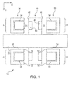
- FIG. 1 a partial view of an exemplary embodiment of the rotary transformer in accordance with the disclosure is shown in Fig. 1 and is designated generally by reference character 10.
- FIG. 2 Other embodiments of rotary transformers in accordance with the disclosure, or aspects thereof, are provided in Figs. 2 - 5 , as will be described.
- the systems and methods described herein can be used for transferring electrical power between stators and rotors and determining rotor position in electrical machines.
- Rotary transformer 10 includes a shaft 20, a first stator 30, a rotor 40, and a second stator 50.
- Shaft 20 connects to rotor 40 and extends through respective radial gaps 22 and 24 disposed within first and second stators 30 and 50.
- Rotor 40 connects to a source of rotational energy (shown in Fig. 2 ) and is rotatable with respect to first and second stators 30 and 50.
- First and second stators 30 and 50 are each fixed with respect to rotor 40 and with respect to one another.
- First stator 30 includes a first stator pole surface 32 and first stator windings 34.
- First stator pole surface 32 is constructed from a magnetic material, extends about shaft 20, and is separated from shaft 20 by radial gap 22.
- First stator windings 34 are disposed within an annular groove defined in first stator 30 and extend about shaft 20.
- Second stator 50 includes a second stator pole surface 52 and second stator windings 54.
- Second stator pole surface 52 is constructed from a magnetic material, extends about shaft 20, and is separated from shaft 20 by radial gap 24.
- Second stator windings 54 are disposed within an annular groove defined in second stator 50 and extend about shaft 20.
- Second stator pole surface 52 and second stator windings 54 both oppose first stator pole surface 32 and first stator windings 34 of first stator 30.
- Rotor 40 includes a rotor first pole surface 42, rotor first windings 44, a rotor second pole surface 46, and rotor second windings 48.
- Rotor first and second pole surfaces 42 and 46 are constructed from a magnetic material and are disposed on axially opposed faces (ends) of rotor 40.
- Rotor first windings 44 are disposed in a groove defined in rotor first pole surface 42 and extend about shaft 20.
- Rotor second windings 48 are disposed in a groove defined in rotor second pole surface 46 and extend about shaft 20.
- Rotor first pole surface 42 and rotor first windings 44 are axially adjacent to and oppose first stator 30 across a first axial gap 26.
- Rotor second pole surface 46 and rotor second windings 48 are axially adjacent to and oppose second stator 50 across a second axial gap 28.
- First stator 30 electromagnetically couples to rotor 40 such that current flow through first stator windings 34 induces corresponding current flow in rotor first windings 44.
- Second stator 50 electromagnetically couples to rotor 40 such that current flow in second stator windings 54 induces corresponding current flow in rotor second windings 48. This transfers, i.e. transmits, electrical power from first and second stators 30 and 50 to rotor 40.
- electrical machine 100 is shown. As illustrated, electrical machine 100 is a synchronous machine. As will be appreciated, electrical machine 100 can also be a doubly fed induction machine. Electrical machine 100 includes a rotating portion 102, a stationary portion 104, and rotary transformer 10. First and second stators 30 and 50 of rotary transformer 10 are fixed with respect to stationary portion 104. Shaft 20 and rotor 40 are operatively connected to rotating portion 102 for common rotation therewith and rotate with respect to stationary portion 104. Rotating portion 102 also includes main field windings (not shown for clarity purposes) electrically connected to rotor first and second windings 44 and 48 which receive electrical power transmitted contactlessly (i.e. without physical contact) between first and second stators 30 and 50 to rotor 40.
- main field windings not shown for clarity purposes
- First stator 30, second stator 50, and rotor 40 form a Scott-T transformer configured for transforming two-phase electrical power into three-phase electrical power for exciting the main field windings of electrical machine 100. More specifically, sinusoidal excitation electrical power applied to first stator windings 34 at terminals X1 and X2 has the same amplitude and is 90 degrees out of phase with sinusoidal electrical power applied to second stator windings at terminals Y1 and Y2. These current flows induce corresponding current flows in rotor first and second windings 44 and 48. Rotor first and second windings 44 and 48 are tapped as illustrated by circuitry on rotor 40.
- This arrangement allows for converting two-phase electrical power applied across terminals X1, X2, Y1, and Y2 of rotor first and second windings 44 and 48 and synthesizing the power into a balanced three-phase sinusoidal electrical current available at terminals R, S and T of rotor first and second windings 44 and 48.
- the synthesized current can thereafter be provided to main field windings located on rotary portion 102.
- First stator 30 includes first stator pole surface 32 and windings 34.
- First stator 30 also defines an aperture and a first stator periphery 36.
- the aperture forms radial gap 22 that extends about shaft 20.
- First stator periphery 36 defines the outer shape of first stator pole surface 32.
- First stator pole surface 32 in turn is divided into inner and outer annular portions separated by first stator windings 34, the outer annular portion of first stator pole surface 32 being bounded by first stator periphery 36 and having an oblong shape that varies the strength of the magnetic field produced by the pole surface as a function rotation angle.
- first stator pole surface 32 has a longitudinal axis extending in the x-direction and a lateral axis extending in the y-direction, the longitudinal axis being greater in length than the lateral axis.
- the oblong shape of first stator pole surface is elliptical.
- first stator periphery 36 can form other non-circular shapes as suitable for a given application.
- Second stator 50 is similar to first stator 30 and additionally includes a second stator periphery 56.
- the outer annular portion of second stator pole surface 52 has an oblong shape corresponding to that of first stator pole surface 32 (shown in Fig. 3A ) and rotationally offset therefrom by 90 degrees relative to shaft 20.
- second stator 50 can be rotationally offset from first stator 30 by other values as suitable for inserting positional information on electrical current transferred to rotor 40 from first and second stators 35 and 50.
- a first face of rotor 40 includes rotor first pole surface 42 and rotor first windings 44.
- Rotor first pole surface 42 is divided between an inner and an outer annular portion separated by rotor first windings 44.
- a second face of rotor 40 is shown. The second face of rotor 40 is similar to the first face and additionally includes rotor second pole surface 46 and rotor second windings 48.
- Rotor periphery 49 has an oblong shape with a longitudinal axis extending in the x-direction and a lateral axis extending in the y-direction in the rotor position illustrated in Fig. 3C and Fig. 3D similar to that of first and second stators 30 and 50.
- the longitudinal axis is longer than the lateral axis.
- rotor 30 has an elliptical shape.
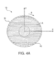
- Rotor 40 overlaps both first stator 30 and second stator 50. As rotor 40 rotates the overlap areas between rotor 40 and first stator 30 as well as that between rotor 40 and second stator 50 changes. In a first rotational position (shown in Fig. 4A ), rotor 40 and first stator 30 have a first overlap area A. In a second rotational position offset by 90 degrees from the first rotational position (shown in Fig. 4B ), rotor 40 and first stator 30 have a second overlap area B. First overlap A is greater than second overlap area B. Since overlap area influences reluctance along the flux path between opposing pole surfaces, a rotation of rotor 40 superimposes a position-reflected current onto an excitation current waveform input to first and second stators 30 and 50.
- first and second stators 30 and 50 are shown offset in rotation from one another by 90 degrees with respect to the axis of shaft 20. This provides for sensing rotor angular position with similar results to conventional reluctance resolvers (position sensors). Moreover, as rotor 40 does not cut magnetic flux lines respectively extending between first and second stators 30 and 50 and rotor 40, excitation is independent of rotation speed or slip frequency, thereby simplifying excitation control.
- Embodiments of rotary transformers described herein can transfer current to the rotor of electrical machines as a balanced three-phase excitation current without mechanical contact.
- Embodiments of rotary transformers described herein can provide excitation control that is independent of rotor speed or slip frequency.
- Embodiments of rotary transformers described herein can also effect three-phase power transfer using a single rotor, such as a rotor disk for example.
- Embodiments of rotary transformers described herein can provide rotor position sensing using a Scott-T transformer and without the use of an independent measurement device, such as an external resolver or encoder for example.
- Embodiments of rotary transformers described herein can be used in synchronous machines or in doubly fed induction machines.
- synchronous machines the balanced three-phase voltage induced at terminals R, S, and T can be rectified using diode bridge (not shown for reasons of clarity) mounted on the rotor. The resulting direct current output from the diode bridge can be used to power up the machine main field winding.
- doubly fed induction machines terminals R, S, and T are direction connected to the three-phase main rotor windings of the machine to generate a rotating magnetic field.
Landscapes
- Engineering & Computer Science (AREA)
- Power Engineering (AREA)
- Microelectronics & Electronic Packaging (AREA)
Applications Claiming Priority (1)
| Application Number | Priority Date | Filing Date | Title |
|---|---|---|---|
| US14/179,376 US9520229B2 (en) | 2014-02-12 | 2014-02-12 | Rotary transformers for electrical machines |
Publications (3)
| Publication Number | Publication Date |
|---|---|
| EP2908413A2 true EP2908413A2 (fr) | 2015-08-19 |
| EP2908413A3 EP2908413A3 (fr) | 2016-07-27 |
| EP2908413B1 EP2908413B1 (fr) | 2019-12-18 |
Family
ID=52598579
Family Applications (1)
| Application Number | Title | Priority Date | Filing Date |
|---|---|---|---|
| EP15154525.8A Active EP2908413B1 (fr) | 2014-02-12 | 2015-02-10 | Transformateurs rotatifs pour machines électriques |
Country Status (2)
| Country | Link |
|---|---|
| US (1) | US9520229B2 (fr) |
| EP (1) | EP2908413B1 (fr) |
Cited By (1)
| Publication number | Priority date | Publication date | Assignee | Title |
|---|---|---|---|---|
| WO2025119534A1 (fr) * | 2023-12-06 | 2025-06-12 | Scania Cv Ab | Transformateur rotatif |
Families Citing this family (2)
| Publication number | Priority date | Publication date | Assignee | Title |
|---|---|---|---|---|
| US10498279B2 (en) * | 2015-11-23 | 2019-12-03 | Abb Schweiz Ag | Electromagnetic machine system having current injection for inductive excitation of windings |
| DE102023203356A1 (de) * | 2023-04-13 | 2024-10-17 | Zf Friedrichshafen Ag | Antriebsachse für ein Elektrofahrzeug |
Family Cites Families (28)
| Publication number | Priority date | Publication date | Assignee | Title |
|---|---|---|---|---|
| US2585050A (en) * | 1949-01-07 | 1952-02-12 | Beatrice George Marti | Variable transformer |
| SE7505390L (sv) * | 1974-06-12 | 1975-12-15 | Nasa | Kommutatorfri likstromsmotor. |
| US4612503A (en) * | 1980-10-21 | 1986-09-16 | Kabushiki Kaisha S G | Rotation speed detection device having a rotation angle detector of inductive type |
| US4612486A (en) * | 1985-04-19 | 1986-09-16 | Itsuki Ban | Semiconductor electric motor having a rotary transformer to excite a rotor |
| JP2988597B2 (ja) * | 1991-08-27 | 1999-12-13 | 株式会社エスジー | 回転位置検出装置 |
| US5585709A (en) * | 1993-12-22 | 1996-12-17 | Wisconsin Alumni Research Foundation | Method and apparatus for transducerless position and velocity estimation in drives for AC machines |
| JP4002308B2 (ja) | 1995-08-10 | 2007-10-31 | 株式会社アミテック | 誘導型回転位置検出装置 |
| US5770909A (en) * | 1996-12-13 | 1998-06-23 | Rosen Motors, L.P. | Wound rotor synchronous motor-generator and field control system therefor |
| US6512437B2 (en) * | 1997-07-03 | 2003-01-28 | The Furukawa Electric Co., Ltd. | Isolation transformer |
| DE19810566A1 (de) * | 1997-07-24 | 1999-09-16 | Frank Eckert | Elektrodynamische Maschine, nämlich Synchrongenerator und/oder -motor |
| US6278212B1 (en) * | 1999-07-07 | 2001-08-21 | American Superconductor Corp. | Exciter with axial gap |
| JP4225150B2 (ja) | 2003-08-12 | 2009-02-18 | アイシン・エィ・ダブリュ株式会社 | 電動駆動制御装置及び電動駆動制御方法 |
| DE10344055A1 (de) * | 2003-09-23 | 2005-04-21 | Siemens Ag | Induktiver Drehübertrager |
| GB2408154A (en) * | 2003-11-07 | 2005-05-18 | Newage Int Ltd | Stator/rotor arrangement and exciter for an axial flux AC machine |
| JP2005223969A (ja) * | 2004-02-03 | 2005-08-18 | Minebea Co Ltd | バリアブルリラクタンスレゾルバおよびその製造方法、製造装置 |
| DE102005047451A1 (de) * | 2005-09-30 | 2007-04-12 | Siemens Ag | Synchronmaschine |
| US7197113B1 (en) * | 2005-12-01 | 2007-03-27 | General Electric Company | Contactless power transfer system |
| JP2008111737A (ja) | 2006-10-31 | 2008-05-15 | Furukawa Electric Co Ltd:The | 回転センサ |
| JP2010104145A (ja) | 2008-10-23 | 2010-05-06 | Aisin Aw Co Ltd | 回転電機 |
| EP2602917B1 (fr) | 2010-08-04 | 2020-07-22 | Mitsubishi Electric Corporation | Machine électrique rotative |
| US8542085B2 (en) * | 2011-02-28 | 2013-09-24 | GM Global Technology Operations LLC | High frequency rotary transformer for synchronous electrical machines |
| US8593095B2 (en) * | 2011-05-24 | 2013-11-26 | Hamilton Sundstrand Corporation | Wound field synchronous machine rotor tracking using a carrier injection sensorless signal and exciter current |
| JP2013021810A (ja) | 2011-07-11 | 2013-01-31 | Jtekt Corp | 回転電機 |
| US20140340185A1 (en) * | 2011-08-16 | 2014-11-20 | Pierce Verleur | Rotary Connection for Electric Power Transmission |
| WO2013119356A2 (fr) * | 2012-02-07 | 2013-08-15 | Fxq Engineering Group, Llc | Moteur électrique possédant un rotor approximativement en forme d'ellipse |
| JP2013198261A (ja) * | 2012-03-19 | 2013-09-30 | Denso Corp | 回転電機の励磁装置 |
| JPWO2013172315A1 (ja) * | 2012-05-14 | 2016-01-12 | 株式会社アミテック | 位置検出装置 |
| US9543876B2 (en) * | 2013-06-20 | 2017-01-10 | Hamilton Sundstrand Corporation | Three phase flux switching generator in a three stage wound field synchronous machine |
-
2014
- 2014-02-12 US US14/179,376 patent/US9520229B2/en active Active
-
2015
- 2015-02-10 EP EP15154525.8A patent/EP2908413B1/fr active Active
Non-Patent Citations (1)
| Title |
|---|
| None |
Cited By (1)
| Publication number | Priority date | Publication date | Assignee | Title |
|---|---|---|---|---|
| WO2025119534A1 (fr) * | 2023-12-06 | 2025-06-12 | Scania Cv Ab | Transformateur rotatif |
Also Published As
| Publication number | Publication date |
|---|---|
| US20150228405A1 (en) | 2015-08-13 |
| US9520229B2 (en) | 2016-12-13 |
| EP2908413A3 (fr) | 2016-07-27 |
| EP2908413B1 (fr) | 2019-12-18 |
Similar Documents
| Publication | Publication Date | Title |
|---|---|---|
| EP0254347B1 (fr) | Machine électrique | |
| TWI383412B (zh) | 旋轉角偵測或同步裝置用繞阻之捲繞方法 | |
| JP2597617B2 (ja) | 回転変換器 | |
| US10992190B2 (en) | Self-exciting synchronous reluctance generators | |
| CN105850014B (zh) | 旋转变压器装置、电动机以及驱动器 | |
| EP2853861B1 (fr) | Dispositif de détection de position | |
| JP2017106899A (ja) | 回転子シャフトの軸線方向位置を検出するためのデバイスならびに回転機械に対してのそれの応用 | |
| US20180254688A1 (en) | Wound-rotor synchronous machine with permanent magnets | |
| EP2592728B1 (fr) | Dispositif électromagnétique | |
| EP2908413B1 (fr) | Transformateurs rotatifs pour machines électriques | |
| CN108027253B (zh) | 无刷旋转变压器及旋转角度检测装置 | |
| CN109716618A (zh) | 旋转电机 | |
| JP3085989B2 (ja) | 測定電気量及び/又は電気エネルギーを回転子と固定子との間で無接触で誘導的に伝送する装置 | |
| US20240333097A1 (en) | Electric motor with an energy-harvesting device | |
| KR102293611B1 (ko) | 리졸버 | |
| JP2003232654A (ja) | ブラシレスレゾルバ | |
| CN110192332A (zh) | 电机 | |
| CN105827077B (zh) | 旋转电机 | |
| US20120176006A1 (en) | Electric machine having integrated resolver | |
| JP7766395B2 (ja) | 回転機械 | |
| CN209982293U (zh) | 一种具有速度同步检测功能的电机结构 | |
| CN109341731A (zh) | 一种用于测量双转子电机相对位置的传感器 | |
| JPH07264798A (ja) | 軸受兼用モータ及びその制御方法 | |
| JP2004163186A (ja) | 回転検出器 | |
| JPH0989516A (ja) | 位置検出装置用付加装置 |
Legal Events
| Date | Code | Title | Description |
|---|---|---|---|
| PUAI | Public reference made under article 153(3) epc to a published international application that has entered the european phase |
Free format text: ORIGINAL CODE: 0009012 |
|
| AK | Designated contracting states |
Kind code of ref document: A2 Designated state(s): AL AT BE BG CH CY CZ DE DK EE ES FI FR GB GR HR HU IE IS IT LI LT LU LV MC MK MT NL NO PL PT RO RS SE SI SK SM TR |
|
| AX | Request for extension of the european patent |
Extension state: BA ME |
|
| PUAL | Search report despatched |
Free format text: ORIGINAL CODE: 0009013 |
|
| AK | Designated contracting states |
Kind code of ref document: A3 Designated state(s): AL AT BE BG CH CY CZ DE DK EE ES FI FR GB GR HR HU IE IS IT LI LT LU LV MC MK MT NL NO PL PT RO RS SE SI SK SM TR |
|
| AX | Request for extension of the european patent |
Extension state: BA ME |
|
| RIC1 | Information provided on ipc code assigned before grant |
Ipc: H02K 19/38 20060101AFI20160617BHEP Ipc: H02K 11/00 20160101ALI20160617BHEP Ipc: H01F 38/18 20060101ALI20160617BHEP |
|
| STAA | Information on the status of an ep patent application or granted ep patent |
Free format text: STATUS: REQUEST FOR EXAMINATION WAS MADE |
|
| 17P | Request for examination filed |
Effective date: 20170125 |
|
| RBV | Designated contracting states (corrected) |
Designated state(s): AL AT BE BG CH CY CZ DE DK EE ES FI FR GB GR HR HU IE IS IT LI LT LU LV MC MK MT NL NO PL PT RO RS SE SI SK SM TR |
|
| REG | Reference to a national code |
Ref country code: DE Ref legal event code: R079 Ref document number: 602015043703 Country of ref document: DE Free format text: PREVIOUS MAIN CLASS: H02K0019380000 Ipc: H02K0011225000 |
|
| GRAP | Despatch of communication of intention to grant a patent |
Free format text: ORIGINAL CODE: EPIDOSNIGR1 |
|
| STAA | Information on the status of an ep patent application or granted ep patent |
Free format text: STATUS: GRANT OF PATENT IS INTENDED |
|
| RIC1 | Information provided on ipc code assigned before grant |
Ipc: H02K 11/225 20150819AFI20181106BHEP Ipc: H01F 38/18 20060101ALI20181106BHEP Ipc: H02K 19/38 20060101ALI20181106BHEP Ipc: H02K 11/00 20060101ALI20181106BHEP |
|
| INTG | Intention to grant announced |
Effective date: 20181129 |
|
| RIC1 | Information provided on ipc code assigned before grant |
Ipc: H02K 11/225 20160101AFI20181106BHEP Ipc: H01F 38/18 20060101ALI20181106BHEP Ipc: H02K 11/00 20160101ALI20181106BHEP Ipc: H02K 19/38 20060101ALI20181106BHEP |
|
| RIC1 | Information provided on ipc code assigned before grant |
Ipc: H01F 38/18 20060101ALI20181106BHEP Ipc: H02K 19/38 20060101ALI20181106BHEP Ipc: H02K 11/225 20160101AFI20181106BHEP Ipc: H02K 11/00 20160101ALI20181106BHEP |
|
| GRAJ | Information related to disapproval of communication of intention to grant by the applicant or resumption of examination proceedings by the epo deleted |
Free format text: ORIGINAL CODE: EPIDOSDIGR1 |
|
| STAA | Information on the status of an ep patent application or granted ep patent |
Free format text: STATUS: REQUEST FOR EXAMINATION WAS MADE |
|
| GRAP | Despatch of communication of intention to grant a patent |
Free format text: ORIGINAL CODE: EPIDOSNIGR1 |
|
| STAA | Information on the status of an ep patent application or granted ep patent |
Free format text: STATUS: GRANT OF PATENT IS INTENDED |
|
| INTC | Intention to grant announced (deleted) | ||
| INTG | Intention to grant announced |
Effective date: 20190507 |
|
| GRAS | Grant fee paid |
Free format text: ORIGINAL CODE: EPIDOSNIGR3 |
|
| GRAA | (expected) grant |
Free format text: ORIGINAL CODE: 0009210 |
|
| STAA | Information on the status of an ep patent application or granted ep patent |
Free format text: STATUS: THE PATENT HAS BEEN GRANTED |
|
| AK | Designated contracting states |
Kind code of ref document: B1 Designated state(s): AL AT BE BG CH CY CZ DE DK EE ES FI FR GB GR HR HU IE IS IT LI LT LU LV MC MK MT NL NO PL PT RO RS SE SI SK SM TR |
|
| REG | Reference to a national code |
Ref country code: CH Ref legal event code: EP |
|
| REG | Reference to a national code |
Ref country code: IE Ref legal event code: FG4D |
|
| REG | Reference to a national code |
Ref country code: DE Ref legal event code: R096 Ref document number: 602015043703 Country of ref document: DE |
|
| REG | Reference to a national code |
Ref country code: AT Ref legal event code: REF Ref document number: 1215654 Country of ref document: AT Kind code of ref document: T Effective date: 20200115 |
|
| REG | Reference to a national code |
Ref country code: NL Ref legal event code: MP Effective date: 20191218 |
|
| PG25 | Lapsed in a contracting state [announced via postgrant information from national office to epo] |
Ref country code: GR Free format text: LAPSE BECAUSE OF FAILURE TO SUBMIT A TRANSLATION OF THE DESCRIPTION OR TO PAY THE FEE WITHIN THE PRESCRIBED TIME-LIMIT Effective date: 20200319 Ref country code: NO Free format text: LAPSE BECAUSE OF FAILURE TO SUBMIT A TRANSLATION OF THE DESCRIPTION OR TO PAY THE FEE WITHIN THE PRESCRIBED TIME-LIMIT Effective date: 20200318 Ref country code: LV Free format text: LAPSE BECAUSE OF FAILURE TO SUBMIT A TRANSLATION OF THE DESCRIPTION OR TO PAY THE FEE WITHIN THE PRESCRIBED TIME-LIMIT Effective date: 20191218 Ref country code: SE Free format text: LAPSE BECAUSE OF FAILURE TO SUBMIT A TRANSLATION OF THE DESCRIPTION OR TO PAY THE FEE WITHIN THE PRESCRIBED TIME-LIMIT Effective date: 20191218 Ref country code: LT Free format text: LAPSE BECAUSE OF FAILURE TO SUBMIT A TRANSLATION OF THE DESCRIPTION OR TO PAY THE FEE WITHIN THE PRESCRIBED TIME-LIMIT Effective date: 20191218 Ref country code: BG Free format text: LAPSE BECAUSE OF FAILURE TO SUBMIT A TRANSLATION OF THE DESCRIPTION OR TO PAY THE FEE WITHIN THE PRESCRIBED TIME-LIMIT Effective date: 20200318 Ref country code: FI Free format text: LAPSE BECAUSE OF FAILURE TO SUBMIT A TRANSLATION OF THE DESCRIPTION OR TO PAY THE FEE WITHIN THE PRESCRIBED TIME-LIMIT Effective date: 20191218 |
|
| REG | Reference to a national code |
Ref country code: LT Ref legal event code: MG4D |
|
| PG25 | Lapsed in a contracting state [announced via postgrant information from national office to epo] |
Ref country code: HR Free format text: LAPSE BECAUSE OF FAILURE TO SUBMIT A TRANSLATION OF THE DESCRIPTION OR TO PAY THE FEE WITHIN THE PRESCRIBED TIME-LIMIT Effective date: 20191218 Ref country code: RS Free format text: LAPSE BECAUSE OF FAILURE TO SUBMIT A TRANSLATION OF THE DESCRIPTION OR TO PAY THE FEE WITHIN THE PRESCRIBED TIME-LIMIT Effective date: 20191218 |
|
| PG25 | Lapsed in a contracting state [announced via postgrant information from national office to epo] |
Ref country code: AL Free format text: LAPSE BECAUSE OF FAILURE TO SUBMIT A TRANSLATION OF THE DESCRIPTION OR TO PAY THE FEE WITHIN THE PRESCRIBED TIME-LIMIT Effective date: 20191218 |
|
| PG25 | Lapsed in a contracting state [announced via postgrant information from national office to epo] |
Ref country code: EE Free format text: LAPSE BECAUSE OF FAILURE TO SUBMIT A TRANSLATION OF THE DESCRIPTION OR TO PAY THE FEE WITHIN THE PRESCRIBED TIME-LIMIT Effective date: 20191218 Ref country code: NL Free format text: LAPSE BECAUSE OF FAILURE TO SUBMIT A TRANSLATION OF THE DESCRIPTION OR TO PAY THE FEE WITHIN THE PRESCRIBED TIME-LIMIT Effective date: 20191218 Ref country code: PT Free format text: LAPSE BECAUSE OF FAILURE TO SUBMIT A TRANSLATION OF THE DESCRIPTION OR TO PAY THE FEE WITHIN THE PRESCRIBED TIME-LIMIT Effective date: 20200513 Ref country code: CZ Free format text: LAPSE BECAUSE OF FAILURE TO SUBMIT A TRANSLATION OF THE DESCRIPTION OR TO PAY THE FEE WITHIN THE PRESCRIBED TIME-LIMIT Effective date: 20191218 Ref country code: RO Free format text: LAPSE BECAUSE OF FAILURE TO SUBMIT A TRANSLATION OF THE DESCRIPTION OR TO PAY THE FEE WITHIN THE PRESCRIBED TIME-LIMIT Effective date: 20191218 |
|
| PG25 | Lapsed in a contracting state [announced via postgrant information from national office to epo] |
Ref country code: SM Free format text: LAPSE BECAUSE OF FAILURE TO SUBMIT A TRANSLATION OF THE DESCRIPTION OR TO PAY THE FEE WITHIN THE PRESCRIBED TIME-LIMIT Effective date: 20191218 Ref country code: SK Free format text: LAPSE BECAUSE OF FAILURE TO SUBMIT A TRANSLATION OF THE DESCRIPTION OR TO PAY THE FEE WITHIN THE PRESCRIBED TIME-LIMIT Effective date: 20191218 Ref country code: IS Free format text: LAPSE BECAUSE OF FAILURE TO SUBMIT A TRANSLATION OF THE DESCRIPTION OR TO PAY THE FEE WITHIN THE PRESCRIBED TIME-LIMIT Effective date: 20200418 |
|
| REG | Reference to a national code |
Ref country code: DE Ref legal event code: R097 Ref document number: 602015043703 Country of ref document: DE |
|
| REG | Reference to a national code |
Ref country code: CH Ref legal event code: PL |
|
| REG | Reference to a national code |
Ref country code: AT Ref legal event code: MK05 Ref document number: 1215654 Country of ref document: AT Kind code of ref document: T Effective date: 20191218 |
|
| PLBE | No opposition filed within time limit |
Free format text: ORIGINAL CODE: 0009261 |
|
| STAA | Information on the status of an ep patent application or granted ep patent |
Free format text: STATUS: NO OPPOSITION FILED WITHIN TIME LIMIT |
|
| REG | Reference to a national code |
Ref country code: BE Ref legal event code: MM Effective date: 20200229 |
|
| PG25 | Lapsed in a contracting state [announced via postgrant information from national office to epo] |
Ref country code: MC Free format text: LAPSE BECAUSE OF FAILURE TO SUBMIT A TRANSLATION OF THE DESCRIPTION OR TO PAY THE FEE WITHIN THE PRESCRIBED TIME-LIMIT Effective date: 20191218 Ref country code: ES Free format text: LAPSE BECAUSE OF FAILURE TO SUBMIT A TRANSLATION OF THE DESCRIPTION OR TO PAY THE FEE WITHIN THE PRESCRIBED TIME-LIMIT Effective date: 20191218 Ref country code: DK Free format text: LAPSE BECAUSE OF FAILURE TO SUBMIT A TRANSLATION OF THE DESCRIPTION OR TO PAY THE FEE WITHIN THE PRESCRIBED TIME-LIMIT Effective date: 20191218 Ref country code: LU Free format text: LAPSE BECAUSE OF NON-PAYMENT OF DUE FEES Effective date: 20200210 |
|
| 26N | No opposition filed |
Effective date: 20200921 |
|
| PG25 | Lapsed in a contracting state [announced via postgrant information from national office to epo] |
Ref country code: LI Free format text: LAPSE BECAUSE OF NON-PAYMENT OF DUE FEES Effective date: 20200229 Ref country code: AT Free format text: LAPSE BECAUSE OF FAILURE TO SUBMIT A TRANSLATION OF THE DESCRIPTION OR TO PAY THE FEE WITHIN THE PRESCRIBED TIME-LIMIT Effective date: 20191218 Ref country code: CH Free format text: LAPSE BECAUSE OF NON-PAYMENT OF DUE FEES Effective date: 20200229 Ref country code: SI Free format text: LAPSE BECAUSE OF FAILURE TO SUBMIT A TRANSLATION OF THE DESCRIPTION OR TO PAY THE FEE WITHIN THE PRESCRIBED TIME-LIMIT Effective date: 20191218 |
|
| PG25 | Lapsed in a contracting state [announced via postgrant information from national office to epo] |
Ref country code: IE Free format text: LAPSE BECAUSE OF NON-PAYMENT OF DUE FEES Effective date: 20200210 Ref country code: IT Free format text: LAPSE BECAUSE OF FAILURE TO SUBMIT A TRANSLATION OF THE DESCRIPTION OR TO PAY THE FEE WITHIN THE PRESCRIBED TIME-LIMIT Effective date: 20191218 |
|
| PG25 | Lapsed in a contracting state [announced via postgrant information from national office to epo] |
Ref country code: BE Free format text: LAPSE BECAUSE OF NON-PAYMENT OF DUE FEES Effective date: 20200229 Ref country code: PL Free format text: LAPSE BECAUSE OF FAILURE TO SUBMIT A TRANSLATION OF THE DESCRIPTION OR TO PAY THE FEE WITHIN THE PRESCRIBED TIME-LIMIT Effective date: 20191218 |
|
| PG25 | Lapsed in a contracting state [announced via postgrant information from national office to epo] |
Ref country code: TR Free format text: LAPSE BECAUSE OF FAILURE TO SUBMIT A TRANSLATION OF THE DESCRIPTION OR TO PAY THE FEE WITHIN THE PRESCRIBED TIME-LIMIT Effective date: 20191218 Ref country code: MT Free format text: LAPSE BECAUSE OF FAILURE TO SUBMIT A TRANSLATION OF THE DESCRIPTION OR TO PAY THE FEE WITHIN THE PRESCRIBED TIME-LIMIT Effective date: 20191218 Ref country code: CY Free format text: LAPSE BECAUSE OF FAILURE TO SUBMIT A TRANSLATION OF THE DESCRIPTION OR TO PAY THE FEE WITHIN THE PRESCRIBED TIME-LIMIT Effective date: 20191218 |
|
| PG25 | Lapsed in a contracting state [announced via postgrant information from national office to epo] |
Ref country code: MK Free format text: LAPSE BECAUSE OF FAILURE TO SUBMIT A TRANSLATION OF THE DESCRIPTION OR TO PAY THE FEE WITHIN THE PRESCRIBED TIME-LIMIT Effective date: 20191218 |
|
| P01 | Opt-out of the competence of the unified patent court (upc) registered |
Effective date: 20230522 |
|
| PGFP | Annual fee paid to national office [announced via postgrant information from national office to epo] |
Ref country code: GB Payment date: 20260121 Year of fee payment: 12 |
|
| PGFP | Annual fee paid to national office [announced via postgrant information from national office to epo] |
Ref country code: DE Payment date: 20260121 Year of fee payment: 12 |
|
| PGFP | Annual fee paid to national office [announced via postgrant information from national office to epo] |
Ref country code: FR Payment date: 20260121 Year of fee payment: 12 |