EP2908414A1 - Equilibrage des tensions des condensateurs des cellules d'un convertisseur modulaire multi-niveaux - Google Patents
Equilibrage des tensions des condensateurs des cellules d'un convertisseur modulaire multi-niveaux Download PDFInfo
- Publication number
- EP2908414A1 EP2908414A1 EP14155197.8A EP14155197A EP2908414A1 EP 2908414 A1 EP2908414 A1 EP 2908414A1 EP 14155197 A EP14155197 A EP 14155197A EP 2908414 A1 EP2908414 A1 EP 2908414A1
- Authority
- EP
- European Patent Office
- Prior art keywords
- converter
- branch
- band pass
- pass filter
- cell
- Prior art date
- Legal status (The legal status is an assumption and is not a legal conclusion. Google has not performed a legal analysis and makes no representation as to the accuracy of the status listed.)
- Withdrawn
Links
- 239000003990 capacitor Substances 0.000 title claims abstract description 57
- 239000004065 semiconductor Substances 0.000 claims abstract description 10
- 238000000034 method Methods 0.000 claims description 16
- 230000000737 periodic effect Effects 0.000 claims description 3
- 210000004027 cell Anatomy 0.000 description 92
- 230000008901 benefit Effects 0.000 description 6
- 230000007246 mechanism Effects 0.000 description 6
- 238000010586 diagram Methods 0.000 description 4
- 230000001419 dependent effect Effects 0.000 description 3
- 210000004460 N cell Anatomy 0.000 description 2
- 238000001228 spectrum Methods 0.000 description 2
- 230000002238 attenuated effect Effects 0.000 description 1
- 230000009286 beneficial effect Effects 0.000 description 1
- 238000009826 distribution Methods 0.000 description 1
- 230000008569 process Effects 0.000 description 1
- 230000009467 reduction Effects 0.000 description 1
- 238000009827 uniform distribution Methods 0.000 description 1
Images


Classifications
-
- H—ELECTRICITY
- H02—GENERATION; CONVERSION OR DISTRIBUTION OF ELECTRIC POWER
- H02M—APPARATUS FOR CONVERSION BETWEEN AC AND AC, BETWEEN AC AND DC, OR BETWEEN DC AND DC, AND FOR USE WITH MAINS OR SIMILAR POWER SUPPLY SYSTEMS; CONVERSION OF DC OR AC INPUT POWER INTO SURGE OUTPUT POWER; CONTROL OR REGULATION THEREOF
- H02M1/00—Details of apparatus for conversion
- H02M1/12—Arrangements for reducing harmonics from AC input or output
- H02M1/126—Arrangements for reducing harmonics from AC input or output using passive filters
-
- H—ELECTRICITY
- H02—GENERATION; CONVERSION OR DISTRIBUTION OF ELECTRIC POWER
- H02M—APPARATUS FOR CONVERSION BETWEEN AC AND AC, BETWEEN AC AND DC, OR BETWEEN DC AND DC, AND FOR USE WITH MAINS OR SIMILAR POWER SUPPLY SYSTEMS; CONVERSION OF DC OR AC INPUT POWER INTO SURGE OUTPUT POWER; CONTROL OR REGULATION THEREOF
- H02M7/00—Conversion of AC power input into DC power output; Conversion of DC power input into AC power output
- H02M7/42—Conversion of DC power input into AC power output without possibility of reversal
- H02M7/44—Conversion of DC power input into AC power output without possibility of reversal by static converters
- H02M7/48—Conversion of DC power input into AC power output without possibility of reversal by static converters using discharge tubes with control electrode or semiconductor devices with control electrode
- H02M7/483—Converters with outputs that each can have more than two voltages levels
- H02M7/4835—Converters with outputs that each can have more than two voltages levels comprising two or more cells, each including a switchable capacitor, the capacitors having a nominal charge voltage which corresponds to a given fraction of the input voltage, and the capacitors being selectively connected in series to determine the instantaneous output voltage
Definitions
- the invention relates to a modular multilevel converter and a method for balancing cell capacitor voltages of such a converter.
- Modular multilevel converters may be characterized by converter branches that comprise series-connected converter cells and are usually used in medium and high voltage applications.
- the modular structure of a modular multilevel converter offers a number of advantages over other available multilevel converter topologies.
- a modular multilevel converter usually also exhibits a natural balancing (also called self-balancing) mechanism. For example, this mechanism may be activated when the different converter cells in a converter branch are supplied with the same switching information albeit phase shifted.
- balancing also called self-balancing
- An aspect of the invention relates to a modular multilevel converter.
- the converter may be adapted for converting a DC current into an AC current and/or vice versa.
- the converter may be adapted for converting a single or multi-phase current into another single or multi-phase.
- the converter may connect a load or power source with a power grid or may interconnect two power grids.
- the converter comprises at least one converter branch with at least two series-connected converter cells, each converter cell comprising a cell capacitor and at least one semiconductor switch for connecting the cell capacitor to the branch and for bypassing the cell capacitor.
- the converter may comprise any number of converter cells per converter branch. Each cell may be provided in a cell module carrying the cell capacitor and the semiconductor switch. This may characterize the modularity of the converter.
- each converter cell For a DC/AC (indirect) modular multilevel converter, each converter cell usually comprises a half bridge for connecting the cell capacitor to the branch and for bypassing the cell capacitor.
- each converter cell For AC/AC (direct) or chainlike converters, each converter cell usually comprises a full bridge for connecting the cell capacitor to the branch and for bypassing the cell capacitor.
- the converter comprises a controller for controlling the converter cells of the converter with pulse width modulation according to a predefined switching frequency.
- the controller may comprise a processor with corresponding software, a DSP or FPGA and/or may control the gate units of the converters for connecting and bypassing the converter cells.
- each converter cell may be associated with a periodic carrier signal having the switching frequency and the controller may be adapted for switching the converter cell, when a reference voltage crosses the carrier signal.
- the natural balancing mechanism may rely on the harmonic content of the converter currents.
- the current spectrum of an N-cell modular multilevel converter only consists of the reference voltage frequencies and switching harmonics (and its basebands) at multiples ofNfs, where f s is the switching frequency.
- a converter operating with unmodified phase shifted carrier pulse width modulation may allow a reduction of the switching frequency in very large converters with a large N.
- the implicit multiplication of the switching frequency may be of great benefit.
- the converter comprises a band pass filter connected to the converter branch, which is tuned to a multiple of the switching frequency nf s , wherein, in particular n is a natural number different from N.
- n is a natural number different from N.
- the band pass filter may be seen as a balance booster.
- the band pass filter strengthens the natural balancing mechanism in the converter. This strengthened mechanism may optimize the inherent cell capacitor voltage control loop.
- the relative size of the band pass filter may be small in comparison with the other components of the converter, such as the electric components of a converter cell. Since the balancing process depends on the harmonic current, the current and voltage rating of the filter may be in the region of less than 1% of the load current and voltage.
- a band pass filter may be an electric component connected to the converter branch that has at least one resonant frequency. Currents with a frequency in a band around the resonant frequency may pass the band pass filter nearly unattenuated. Currents outside the resonant frequency band may be attenuated very strong.
- the band pass filter may be inserted in shunt with the current path.
- the impedance at the resonant frequency of the band pass filter is reduced, increasing the harmonics at this frequency. If the resonant frequency of the band pass filter coincides with a multiple of f s that is not a multiple ofN, then the natural balancing of the converter is strengthened.
- the band pass filter may be composed of any electric components.
- the band pass filter comprises an inductor and a capacitor connected in series.
- the band pass filter may comprise an LCR notch filter tuned to any multiple of f s that is not a multiple of N.
- the band pass filter comprises a resistor connected in series with a capacitor and/or an inductor. It may be possible that the resistance of the band pass filter is provided by the inner resistance of the inductor and/or capacitor. However, it also may be possible that the band pass filter comprises a physical resistor component.
- the band pass filter comprises at least two parallel connected single band pass filters.
- a single band pass filter (having only one resonant frequency) may be duplicated to any number, wherein each single band pass filter is tuned to a different multiple of the switching frequency that is not a multiple of Nf s .
- several band pass filter structures may be connected in parallel.
- the band pass filter may be connected in the circulating current path.
- the band pass filter is connected in parallel to the converter cells of the converter branch.
- the band pass filter may be connected with one end to a first of the converter cells and with another end to the last of the converter cells of a converter branch.
- the converter branch comprises a branch inductor connected in series with the converter cells of the converter branch.
- a converter branch comprises a branch inductor for attenuating frequency in the output phase voltage higher than the frequencies of the reference voltage.
- the band pass filter is connected with one end between the converter cells and the branch inductor.
- the band pass filter is connected in parallel to the branch inductor.
- the converter may comprise different topologies, in the following a half bridge converter with two series-connected converter branches and a full bridge chain-link converter are described as examples.
- the converter comprises further two converter branches connected in series between a DC link and providing a phase output between the two converter branches, wherein each converter branch comprises a branch inductor connected between the converter cells of the converter branch and the phase output.
- each converter cell may comprise a half bridge.
- the band pass filter may be connected in parallel to both branch inductors, the band bass filter may be connected in parallel to each branch inductor or the band pass filter may be interconnecting the phase output and a grounding point.
- the converter comprises further three converter branches, which are delta-connected and which provide a phase output at an end of each branch, wherein each converter branch comprises a branch inductor connected between the converter cells of the converter branch and a phase output.
- each converter cell may comprise a full bridge.
- Such a delta-connected chain-link converter may also benefit from the band pass filter.
- a band pass filter may be connected in parallel to the converter cells of each converter branch, a band bass filter may be connected in parallel to each branch inductor or a band bass filter may be connected with one end between the branch inductor and the converter cells of each converter branch and other ends of the band pass filters are star-connected.
- the converter comprises further three converter branches, which are star-connected at a star point and which provide a phase output at an end of each branch, wherein each converter branch comprises a branch inductor connected between the converter cells of the converter branch and either the phase output or the star point.
- each converter cell may comprise a full bridge.
- Such a star-connected chain-link converter may also benefit from the band pass filter.
- a band pass filter may be connected in parallel to the converter cells of each converter branch, a band bass filter may be connected in parallel to each branch inductor, a band bass filter may be connected with one end between the branch inductor and the converter cells of a first converter branch and another end of the band pass filter may be connected between the branch inductor and the converter cells of a second branch.
- the band pass filters may be delta-connected with each other.
- a further aspect of the invention relates to a method for balancing cell capacitor voltages in converter cells of a modular multilevel converter.
- the method may be performed by a controller of the converter supported by electric hardware components connected to the circuit of the converter, such as the band pass filter.
- the method comprises switching at least two converter cells of at least one converter branch of the converter with pulse width modulation according to a predefined switching frequency (in particular with unmodified phase shifted carrier pulse width modulation as described above), each converter cell comprising a cell capacitor and a semiconductor switch for connecting the cell capacitor to the branch and for bypassing the cell capacitor, and balancing cell capacitor voltages with a band pass filter connected to the converter branch, which is tuned to a multiple of the switching frequency.
- a simple control method may be supported by cell capacitor voltage balancing provided by a physical band pass filter.
- the large number of converter cells and the dispersed nature of a converter with N > 3 may make a controller relatively complex, since care may have to be taken to communicate with all converter cells with a minimum time delay.
- phase shifted pulse width modulation is often used.
- a second control objective may be achieving balance in the cell capacitor voltages.
- the method further comprises measuring a current through the band pass filter and determining a difference in cell capacitor voltages from the measured current.
- the currents which do not have frequencies of the number of cells per branch N times the switching frequency f s may be a measure for the unbalance in the capacitor voltages.
- These currents are selected by the band pass filter and may be measured in the band pass filter. Differences in the cell capacitor voltages may be determined by measuring the current in the band pass filter.
- Fig. 1 shows a modular multilevel converter 10 interconnecting a DC link 12 with a phase output 14.
- the DC link 12 comprises two DC sources 16 interconnected in series and connecting to a grounding point 18 between them.
- the converter comprises two series-connected branches 20, which are connected in parallel to the DC link 12.
- Each branch 20 comprises a plurality of converter cells 22 (here two), which are connected in series. Furthermore, each branch 20 comprises a branch inductor L b , 24, which is connected between the converter cells 22 and the phase output 14.
- a load 26 is connected between the phase output 14 and the grounding point 18.
- the converter 10 furthermore comprises a controller 28 for controlling the converter cells 22.
- the converter 10 may have more than one phase.
- the converter 10 may comprise two or more arms of two series-connected branches 10 connected in parallel to the DC link.
- Fig. 2 shows a converter cell 22 for the converter 10 of Fig. 1 .
- the converter cell comprises a cell capacitor 30 connected in parallel to a half bridge 32.
- the half bridge 32 comprises two semiconductor switches 34, which are controlled by the controller 28 and which may connect the capacitor 30 to the respective converter branch 20 or may bypass the capacitor 30.
- Fig. 3 shows a diagram describing unmodified phase shifted carrier pulse width modulation, which may be performed by the controller 28.
- the control of the upper or lower converter branch 20 with two converter cells 22 is described.
- the other one of the branches may be controlled with inverted switching signals.
- Part (a) of the diagram shows a reference signal f r , 36 and two carrier signals f c0 , f c1 , 38 over time t.
- the reference signal 36 may be provided by an outer control loop.
- the two carrier signals 38 are periodic signals (here sawtooth signals) having a frequency of f s and which are phase shifted with respect to each other by 180°.
- a control method for N cells per branch may have N carrier signals that are phase shifted by 360°/N with respect to each other.
- Parts (b) and (c) show how the upper converter cell 20 and the lower converter cell 20 are switched. Every time, the respective carrier signal 38 becomes higher than the reference signal 36, the respective cell 22 is connected to the branch 20 (switching signal s 0 , s 1 , 40 is 1). In the case, the respective carrier signal 38 becomes lower, the respective cell is disconnected from the branch 20 and bypassed.
- Fig. 4 to 7 show auxiliary filter circuits that may be connected between points A and B of the converter 10 of Fig. 1 .
- Each filter circuit comprises a band pass filter 42 comprising a filter inductor L bb , 44, a filter resistor r bb , 46 and a filter capacitor C bb , 48 connected in series.
- the filter resistor 46 is optional or may be seen as the virtual resistance of the band pass filter 42.
- the band pass filter 42 improves the natural balancing properties of the converter 10 operating with unmodified phase shifted carrier pulse width modulation.
- the band pass filter 42 may comprise an RLC notch filter connected across the branch decoupling inductors.
- the resonant frequency (or frequencies) of the band pass filter 42 is tuned to any multiple of the switching frequency f s that is not a multiple of N.
- controller 28 may be adapted for measuring the current in the band pass filter 42. From the current, an unbalance in the cell capacitor voltages of the converter cells 22 may be determined.
- Fig. 5 shows, that the band pass filter 42 may be connected in parallel to both branch inductors 24.
- Fig. 5 shows a band pass filter 42 comprising two single filters 42a, 42b, each of which is connected in parallel to one of the branch inductors 24.
- the midpoint of the two series-connected filters 42a, 42b is connected to the phase output 14.
- the controller 28 may measure the current in both single filters 42a, 42b for determining an unbalance in the capacitor voltages.
- Fig. 6 shows a band pass filter 42 interconnected between the phase output 14 and the grounding point.
- Fig. 7 shows a band pass filter 42 comprising a number of single band pass filters 42a, 42b, 42c connected in parallel. Each single band pass filter 42a, 42b, 42c has a different resonance frequency being a multiple of f s .
- the band pass filter of Fig. 7 is connected like the band pass filter of Fig. 4 . However, also different types of connections as shown above and in the following may be replaced by multiple single band pass filters 42a, 42b, 42c as shown in Fig. 7 .
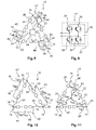
- Fig. 8, 10 and 11 show a modular multilevel converter 10 (chain-link converter) comprising three converter branches 20 that are delta-connected with each other. At their connection points, three phase outputs 14 are provided.
- Fig. 9 shows a converter cell 22 of the converter 10 of Fig. 8, 10 and 11 , the converter cell comprises a cell capacitor 30 and a full bridge 44 of four semiconductor switches 34. With the full bridge 44, the cell capacitor 30 may be bypassed and connected in two directions to its converter branch 20.
- a band pass filter 42 is connected in parallel to each branch inductor 24.
- a band pass filter 42 is connected in parallel to the converter cells 22 of each branch.
- a band pass filter 42 is connected between the branch inductor 24 and the converter cells 22 of the branch 20.
- the other ends of the band pass filters 42 are star-connected.
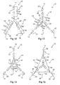
- Fig. 12 to 15 show modular multilevel converters 10 (chain-link converter) comprising three converter branches 20 that are star-connected with each other. At their other ends, three phase outputs 14 are provided.
- the branch inductor 24 of each branch 20 may be either on the side of the star connection or on the side of the phase output 14.
- the converter cells 22 may be full bridge converter cells 22 as shown in Fig. 9 .
- each converter branch 20 is associated with one band pass filter 42, which, with one end, is connected between the converter cells 22 and the branch inductor.
- the band pass filters 42 are connected in parallel to the converter cells 22 of the respective branch 20. I.e. they are connected with their other end to the respective phase output 14.
- the band pass filters 42 are connected in parallel to the branch inductors 24. I.e. they are connected with their other ends to the star point of the converter 10.
- the band pass filters 42 are connected with one end to a first branch 20 and with the other end to a second branch 20. In such a way, the three band pass filters 42 are delta-connected.
- the controller 28 is adapted for controlling the converter cells 22 with pulse width modulation, for example as described with respect to Fig. 3 . Furthermore, the controller 28 may be adapted for measuring the current through all band pass filters 42 connected to the respective converter circuit and for determining an unbalance in the converter 10 based on these measured currents.
Landscapes
- Engineering & Computer Science (AREA)
- Power Engineering (AREA)
- Inverter Devices (AREA)
Priority Applications (1)
| Application Number | Priority Date | Filing Date | Title |
|---|---|---|---|
| EP14155197.8A EP2908414A1 (fr) | 2014-02-14 | 2014-02-14 | Equilibrage des tensions des condensateurs des cellules d'un convertisseur modulaire multi-niveaux |
Applications Claiming Priority (1)
| Application Number | Priority Date | Filing Date | Title |
|---|---|---|---|
| EP14155197.8A EP2908414A1 (fr) | 2014-02-14 | 2014-02-14 | Equilibrage des tensions des condensateurs des cellules d'un convertisseur modulaire multi-niveaux |
Publications (1)
| Publication Number | Publication Date |
|---|---|
| EP2908414A1 true EP2908414A1 (fr) | 2015-08-19 |
Family
ID=50073098
Family Applications (1)
| Application Number | Title | Priority Date | Filing Date |
|---|---|---|---|
| EP14155197.8A Withdrawn EP2908414A1 (fr) | 2014-02-14 | 2014-02-14 | Equilibrage des tensions des condensateurs des cellules d'un convertisseur modulaire multi-niveaux |
Country Status (1)
| Country | Link |
|---|---|
| EP (1) | EP2908414A1 (fr) |
Cited By (1)
| Publication number | Priority date | Publication date | Assignee | Title |
|---|---|---|---|---|
| CN109274285A (zh) * | 2018-10-24 | 2019-01-25 | 南方电网科学研究院有限责任公司 | 一种混合型模块化多电平换流器的电容电压平衡方法 |
Citations (1)
| Publication number | Priority date | Publication date | Assignee | Title |
|---|---|---|---|---|
| US20120068555A1 (en) * | 2010-09-09 | 2012-03-22 | Curtiss-Wright Electro-Mechanical Corporation | System and Method For Controlling A M2LC System |
-
2014
- 2014-02-14 EP EP14155197.8A patent/EP2908414A1/fr not_active Withdrawn
Patent Citations (1)
| Publication number | Priority date | Publication date | Assignee | Title |
|---|---|---|---|---|
| US20120068555A1 (en) * | 2010-09-09 | 2012-03-22 | Curtiss-Wright Electro-Mechanical Corporation | System and Method For Controlling A M2LC System |
Non-Patent Citations (2)
| Title |
|---|
| HUI LIU ET AL: "Review of fault diagnosis and fault-tolerant control for modular multilevel converter of HVDC", IECON 2013 - 39TH ANNUAL CONFERENCE OF THE IEEE INDUSTRIAL ELECTRONICS SOCIETY, IEEE, 10 November 2013 (2013-11-10), pages 1242 - 1247, XP032539694, ISSN: 1553-572X, [retrieved on 20131230], DOI: 10.1109/IECON.2013.6699310 * |
| SZTYKIEL MICHAL ET AL: "Modular multilevel converter modelling, control and analysis under grid frequency deviations", 2013 15TH EUROPEAN CONFERENCE ON POWER ELECTRONICS AND APPLICATIONS (EPE), IEEE, 2 September 2013 (2013-09-02), pages 1 - 11, XP032505085, DOI: 10.1109/EPE.2013.6634747 * |
Cited By (2)
| Publication number | Priority date | Publication date | Assignee | Title |
|---|---|---|---|---|
| CN109274285A (zh) * | 2018-10-24 | 2019-01-25 | 南方电网科学研究院有限责任公司 | 一种混合型模块化多电平换流器的电容电压平衡方法 |
| CN109274285B (zh) * | 2018-10-24 | 2020-04-03 | 南方电网科学研究院有限责任公司 | 一种混合型模块化多电平换流器的电容电压平衡方法 |
Similar Documents
| Publication | Publication Date | Title |
|---|---|---|
| EP2883069B1 (fr) | Procédé et dispositif de contrôle d'un convertisseur multiniveaux | |
| RU2613333C2 (ru) | Многоуровневый преобразователь мощности | |
| US8824169B2 (en) | Multiple inverter and active power filter system | |
| Ramkumar et al. | A new series parallel switched multilevel dc-link inverter topology | |
| CN105379096B (zh) | 用于在交流与直流之间转换的布置、用于控制电力输送模块的方法及装置 | |
| WO2020035527A1 (fr) | Convertisseur de puissance électrique | |
| US11784583B2 (en) | Cascaded pulse width modulation converter control | |
| Jin et al. | Virtual vector-based FCS-MPC for NPC three-level grid-tied inverter without weighting factor of neutral-point voltage balancing | |
| Aleenejad et al. | Unbalanced Selective Harmonic Elimination for fault-tolerant operation of three phase multilevel Cascaded H-bridge inverters | |
| EP3846327A1 (fr) | Procédé de fonctionnement d'un dispositif convertisseur électronique de puissance à cellules flottantes | |
| US9608541B2 (en) | DC-to-AC conversion apparatus and method of operating the same | |
| WO2015136552A2 (fr) | Structure de sous-module de convertisseur modulaire multiniveaux (mmc) permettant de réduire les pertes de commutation | |
| da Silva et al. | Voltage balancing in flying capacitor converter multilevel using space vector modulation | |
| EP2908414A1 (fr) | Equilibrage des tensions des condensateurs des cellules d'un convertisseur modulaire multi-niveaux | |
| Massoud et al. | Mapped hybrid spaced vector modulation for multilevel cascaded-type voltage source inverters | |
| da Silva et al. | Modified sliding-mode observer of capacitor voltages in Modular Multilevel Converter | |
| Zhang et al. | DC-link capacitor voltage balancing for a five-level diode-clamped active power filter using redundant vectors | |
| Renani et al. | Performance evaluation of multicarrier PWM methods for cascaded H-bridge multilevel inverter | |
| Çi̇ftçi̇ et al. | Selection of suitable carrier-based PWM method for Modular Multilevel Converter | |
| Hosseinzadeh et al. | Back-to-back stacked multicell converter | |
| EP3329584B1 (fr) | Montage, procédé et produit programme d'ordinateur pour limiter des courants parasites | |
| Mathe | Performance comparison of the modulators with balancing capability used in MMC applications | |
| Perez et al. | Predictive frequency spectrum shaping of currents in a three phase inverter | |
| JP2016226224A (ja) | モジュラーマルチレベル変換器 | |
| Haederli et al. | Neutral point control in multi level converters applying novel modulation schemes |
Legal Events
| Date | Code | Title | Description |
|---|---|---|---|
| PUAI | Public reference made under article 153(3) epc to a published international application that has entered the european phase |
Free format text: ORIGINAL CODE: 0009012 |
|
| AK | Designated contracting states |
Kind code of ref document: A1 Designated state(s): AL AT BE BG CH CY CZ DE DK EE ES FI FR GB GR HR HU IE IS IT LI LT LU LV MC MK MT NL NO PL PT RO RS SE SI SK SM TR |
|
| AX | Request for extension of the european patent |
Extension state: BA ME |
|
| STAA | Information on the status of an ep patent application or granted ep patent |
Free format text: STATUS: THE APPLICATION IS DEEMED TO BE WITHDRAWN |
|
| 18D | Application deemed to be withdrawn |
Effective date: 20160220 |