EP2908472A1 - Procédé de pilotage d'une installation domotique à multi environnements graphiques - Google Patents
Procédé de pilotage d'une installation domotique à multi environnements graphiques Download PDFInfo
- Publication number
- EP2908472A1 EP2908472A1 EP15153149.8A EP15153149A EP2908472A1 EP 2908472 A1 EP2908472 A1 EP 2908472A1 EP 15153149 A EP15153149 A EP 15153149A EP 2908472 A1 EP2908472 A1 EP 2908472A1
- Authority
- EP
- European Patent Office
- Prior art keywords
- home automation
- graphic
- environments
- content
- screen
- Prior art date
- Legal status (The legal status is an assumption and is not a legal conclusion. Google has not performed a legal analysis and makes no representation as to the accuracy of the status listed.)
- Granted
Links
Images


Classifications
-
- H—ELECTRICITY
- H04—ELECTRIC COMMUNICATION TECHNIQUE
- H04L—TRANSMISSION OF DIGITAL INFORMATION, e.g. TELEGRAPHIC COMMUNICATION
- H04L12/00—Data switching networks
- H04L12/28—Data switching networks characterised by path configuration, e.g. LAN [Local Area Networks] or WAN [Wide Area Networks]
- H04L12/2803—Home automation networks
- H04L12/2816—Controlling appliance services of a home automation network by calling their functionalities
- H04L12/282—Controlling appliance services of a home automation network by calling their functionalities based on user interaction within the home
-
- G—PHYSICS
- G06—COMPUTING OR CALCULATING; COUNTING
- G06F—ELECTRIC DIGITAL DATA PROCESSING
- G06F3/00—Input arrangements for transferring data to be processed into a form capable of being handled by the computer; Output arrangements for transferring data from processing unit to output unit, e.g. interface arrangements
- G06F3/01—Input arrangements or combined input and output arrangements for interaction between user and computer
- G06F3/048—Interaction techniques based on graphical user interfaces [GUI]
- G06F3/0481—Interaction techniques based on graphical user interfaces [GUI] based on specific properties of the displayed interaction object or a metaphor-based environment, e.g. interaction with desktop elements like windows or icons, or assisted by a cursor's changing behaviour or appearance
-
- H—ELECTRICITY
- H04—ELECTRIC COMMUNICATION TECHNIQUE
- H04L—TRANSMISSION OF DIGITAL INFORMATION, e.g. TELEGRAPHIC COMMUNICATION
- H04L12/00—Data switching networks
- H04L12/28—Data switching networks characterised by path configuration, e.g. LAN [Local Area Networks] or WAN [Wide Area Networks]
- H04L12/2803—Home automation networks
- H04L12/2807—Exchanging configuration information on appliance services in a home automation network
- H04L12/2814—Exchanging control software or macros for controlling appliance services in a home automation network
-
- H—ELECTRICITY
- H04—ELECTRIC COMMUNICATION TECHNIQUE
- H04L—TRANSMISSION OF DIGITAL INFORMATION, e.g. TELEGRAPHIC COMMUNICATION
- H04L67/00—Network arrangements or protocols for supporting network services or applications
- H04L67/01—Protocols
- H04L67/12—Protocols specially adapted for proprietary or special-purpose networking environments, e.g. medical networks, sensor networks, networks in vehicles or remote metering networks
- H04L67/125—Protocols specially adapted for proprietary or special-purpose networking environments, e.g. medical networks, sensor networks, networks in vehicles or remote metering networks involving control of end-device applications over a network
-
- H—ELECTRICITY
- H04—ELECTRIC COMMUNICATION TECHNIQUE
- H04L—TRANSMISSION OF DIGITAL INFORMATION, e.g. TELEGRAPHIC COMMUNICATION
- H04L67/00—Network arrangements or protocols for supporting network services or applications
- H04L67/50—Network services
- H04L67/75—Indicating network or usage conditions on the user display
-
- H—ELECTRICITY
- H04—ELECTRIC COMMUNICATION TECHNIQUE
- H04L—TRANSMISSION OF DIGITAL INFORMATION, e.g. TELEGRAPHIC COMMUNICATION
- H04L12/00—Data switching networks
- H04L12/28—Data switching networks characterised by path configuration, e.g. LAN [Local Area Networks] or WAN [Wide Area Networks]
- H04L12/2803—Home automation networks
- H04L2012/284—Home automation networks characterised by the type of medium used
- H04L2012/2841—Wireless
Definitions
- the invention relates to the field of home automation.
- the subject of the invention is more particularly a method for controlling home automation services of a home automation installation.
- the user experience is therefore not ergonomic, this being a brake on the installation and use of different home automation services by said user.
- the purpose of the present invention is to propose a solution to improve the current ergonomics.
- the display step is such that the first and second elements are displayed simultaneously on the screen.
- the display step is performed in such a way that the first and second elements are not displayed simultaneously, the second element comprising interaction elements making it possible to select the content of the first element and to provoke the first element.
- displaying said first element on the screen each of said at least two graphical environments including an interaction element allowing the return to the display of the second element on the screen.
- the two graphic environments share at least common elements of ergonomics.
- the method comprises a step of configuring the desired display on the screen by a user, allowing in particular to adapt as necessary the presentation of the second element.
- the step of displaying the graphic interface on the screen is performed so as to present the first element and the second element, the second element comprising at least two tabs, one of which is active, and each associated with one of said at least two graphical environments, and the graphical environment corresponding to the active tab is displayed on the screen as the content of the first element.
- the method comprises a step of choosing to control a home automation actuator through one or another graphic environment from which the control of the home automation actuator is accessible, or more particularly a choice step driving a home automation actuator through one or another of two graphic environments from which the control of the home automation actuator is accessible.
- the method may include a step wherein at least one of the home automation actuators is operated from two different environments.
- the method may comprise a first step of actuating one of the domotic actuators consecutively to a user interaction step with a function associated with one of said at least two graphic environments contained in the first element, and a second step of actuating said home automation actuator actuated in the first actuation step following a user interaction step with a function associated with another of said at least two graphic environments contained in the first element.
- the method comprises a step of interaction of a user with the content of the first element displayed on the screen from which results a step of actuating at least one of the home automation actuators.
- the invention also relates to a home automation system configured so as to implement the control method and comprising a supervision device, in particular mobile such as a digital tablet or a smart phone, comprising the screen on which is displayed at least one part of the graphical interface and the home automation actuators, at least one of the home automation actuators being connected to the supervision device so that it can be controlled from two different graphical environments.
- a supervision device in particular mobile such as a digital tablet or a smart phone
- the invention also relates to a device for supervising a home automation installation, said device comprising at least two graphic environments respectively associated with different home automation services and allowing the control of home automation actuators of the home automation system, said at least two graphic environments having different graphic charters, and a screen on which is displayed at least a portion of a graphical interface for home automation installation, said graphical interface comprising a first element whose content is selectable among any of said at least two environments graphics and a second element whose content has a main graphic retained regardless of the selected content of the first element and for selecting said content of the first element.
- the device may also include a memory provided with instructions for implementing the control method as described.
- the home automation service control method of a home automation installation comprises a step E1 of supplying at least two graphic environments 101, 102 respectively associated with different home automation services and allowing the control of home automation actuators of the home automation system, said at least two graphical environments 101, 102 having different graphic charters.
- the home automation service control method of a home automation installation comprises a supplying step E1 of at least a first and a second graphic environment 101, 102 respectively associated with first and second home automation services for controlling actuators.
- domotic installation of the home automation system said at least first and second graphics environments 101, 201 respectively having a first and a second graphics.
- the first and second home services are at least partially different.
- the first and second graphic charts are at least partially different.
- a home automation system is defined for a building, or part of a building, with which a user, usually occupying the building or part of the building, is likely to interact, including using the graphical interface.
- graphical environment is meant a set of contents of a graphical interface with which the user can interact to manage all the domotic services associated with the graphical environment, each content offering the user the possibility to manage at the same time. least part of the domotic services associated with the graphical environment.
- Each content of the same graphical environment therefore gives the user access to a portion of the home automation services by enabling him to select and perform functions associated with home automation services, these functions making it possible to control one or more of the home automation actuators.
- graphical chart of a graphical environment it is meant that the graphical environment contains rules for the use of graphic signs which constitute its graphic identity. Thus, all The contents of the same graphical environment retain a visual consistency, allowing the user to easily identify the graphical environment as well as the provider of the associated home-automation services.
- two domotic services respectively associated with two distinct graphic environments can be provided by two separate companies each wanting to provide within their home automation services.
- the use of two different graphic charters makes it possible, on the one hand, for companies not to lose their identifiable graphic identity by a user, and, on the other hand, to avoid any confusion by preserving graphic charters. which the user is used to.
- Figures 2 and 3 illustrate two different graphic environments 101 and 102 with different logos (Logo1 and Logo2) as well as a different presentation representative of the graphical identity of the graphic environment.
- the domotic services associated with the first graphical environment 101 are related to the management of comfort in the habitat.
- Various actuators such as a boiler 103, a shutter 104, a lighting of the ground floor 105 or a floor 106 can implement the comfort functions offered by the home services associated with the first graphical environment 101.
- other home-automation services may relate to security ( figure 3 ), the security functions provided by these home automation services use interactions with one or more actuators of the facility relating to security such as an alarm 107, a smoke detector 108, a motion sensor such as a 109 camera, a lock, etc.
- Roller shutter 104 can also be associated with these home automation services.
- the home automation services referred to above may be generalist and / or expert.
- Domotic services called “generalist” allow for example to give a user control / possible control of a multiplicity of domotic actuators according to basic functions (eg full open / close, lighting 0% / 100%, simplified programming) .
- a butler's function may be associated with these general domotic services, ie a framing function of expert domotic services.
- Domotic services called “experts” can be provided by a partner specialist in a specific field, such as for example security, health, audio-visual) allowing control functions and / or expert programming of a set more restricted domotic actuators.
- the expert home automation services will include associating one or more surveillance cameras, to configure the number of shots per second of a surveillance camera, as well as different levels of alert (beeps, audible alarm, sending messages by preferentially cellular network including SMS messages for "short message service") in case of intrusion detection .
- the method comprises a step E2 in which there is provided a graphical interface comprising a first element 110 whose content is selectable from any one of said at least two graphic environments 101, 102 (in particular, it is possible to select contents of the graphic environments that we wish to display in the first element) and a second element 111 whose content has a main graphic chart preserved whatever the selected content of the first element 110 and for selecting said content of the first element 110.
- the content of the second element 111 makes it possible to select a content of the first element 110 which is representative of one of the graphic environments, from among all the contents of this graphic environment, this content of the first element 110 then being able to be modified .
- the first and second elements 110, 111 are graphical interface entities that can be displayed on a screen.
- the first element 110 and / or second element 111 may for example each be a window of the graphic interface, or a particular zone of a display of the graphical interface reproduced on the screen.
- the method comprises a step E3 display of at least a portion of the graphical interface on a screen.
- displaying at least a portion of the graphical interface it is meant that the elements of the graphical interface are not necessarily displayed at the same time on the screen.
- the second element 111 when the first and second elements 110, 111 of the graphic interface are simultaneously displayed on the screen, the second element 111 extends over a display surface of the graphic interface to screen much lower than the one occupied by the first element 110. In particular, the second element 111 extends over an area less than 10% of the available display area of the graphic interface on the screen.
- the display step is such that the first and second elements 110, 111 are displayed simultaneously on the screen, preferably in the manner described in the particular implementation above.
- the display step E3 is such that the second element 111 is arranged so as to surround the first element ( figure 2 and 3 ).
- the second element 111 then preferably takes the form of a display window border, in which the first element 110 is displayed and provided on one side of a series of selection tabs.
- the second element may be adjacent to the first element (not shown): the second element is then preferentially in the form of a display strip, adjacent to the first element, in which is represented a series of selection tabs .
- the second element may be included in the first element (not shown), especially in the form of an icon appearing in the display area of the first element.
- the display step E3 is performed such that the first 110 and second 111 elements are not displayed simultaneously.
- the second element 111 may include interaction elements 112a, 112b for selecting the content of the first element 110 and causing the display of said first element (and therefore its content) 110 on the screen.
- Each of said at least two graphical environments 101, 102 may include an interaction element 113 for returning the second element 111 to the display on the screen.
- the interaction element 112a, 112b then differs from the second element 111 in that it allows the second element 111 to be displayed, for example in the form of a screen area with a selection menu, from which carried out the selection of the content of the first element 110.
- the transition from the left view to the right view is achieved by a first interaction I 1 , schematized by a hand with the interaction element 112a and the passage from the right-hand view to the left-hand view is performed by a second interaction I 2 , schematized by a hand with the interaction element 113.
- the interaction elements of the second element 111 may each be formed by a button linked to one of the graphical environments, an interaction with the button making it possible, on the one hand, to select the content of the first element 110 and to switch from a display of the second element 111 to a display of the first element 110.
- the interaction element 113 of each of the graphic environments may be a button, for example in the form of a return arrow, whose activation causes the passage of the message. gate of the first element 110 to the display of the second element 111.
- the two graphic environments 101, 102 share at least common elements of ergonomics.
- an action on an interaction element in a first content, associated with one of the graphic environments, of the first element 110 will have the same navigation effect as the action on this interaction element in a second content, associated with another of the graphic environments, of the first element 110.
- the display step E3 is performed so that the provision of different graphical environments 101, 102 is an enjoyableitarian. In fact, this makes it possible to ensure that the choice of the graphic environment 101, 102 from the second element 111 is not favored. In other words, the display step E3 is such that it does not influence the choice of the user as to the domotic services he wishes to activate.
- the second element 111 acts as a selection portal presenting home automation services without the incentive to use one more than another.
- an avatar provision of different graphical environments may include a step of displaying on the screen of a home page (for example with menus), or a common messaging.
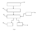
- the method may comprise a configuration step E4 ( figure 1 ) of the desired display on the screen by the user, allowing in particular to adapt as necessary the presentation of the second element 111.
- this E4 configuration step of the display can also allow a user to choose which graphical environment by default it wishes to display as the content of the first element 110 when it initializes the process of piloting (such an initialization can be performed by launching a corresponding software application), or the order in which graphical environments appear on the graphical interface or, more generally, the layout of the content of the second element 111.
- the navigation between the graphical environments 101, 102 comprises the use of tabs 114 belonging to the second element 111.
- the display step E3 of the graphic interface on the screen is made so as to present the first element 110 and the second element 111 (that is to say that the first and second elements - and therefore their contents - are displayed simultaneously).
- the second element 111 then comprises at least two tabs 114, one of which is active, and each associated with one of said at least two graphic environments 101, 102 (this association being preferably one-to-one, that is, one tab points to a single graphical environment and conversely a graphical environment is associated with a single tab).
- the graphic environment corresponding to the active tab is displayed on the screen as the content of the first element 110. Therefore, to implement navigation, the method may comprise a selection step, among said at least two tabs 114, a tab to be activated distinct from the current active tab, then a step of activating the selected tab 114 by modifying the content of the first displayed element 110, said modified content corresponding to the graphical environment 101, 102 associated with said auditing tab to activate so as to bring about a change
- This particular implementation is preferred because it allows a user to switch from one of the graphical environments to any other graphical environment by a single interaction with a tab.
- the control method allows the control of home automation actuators.
- the same home automation actuator can be shared with several home automation services and therefore be operable from different graphical environments 101, 102.
- This allows a user to limit costs without having to duplicate the number of home automation actuators according to the number of services. domotics and / or home service providers.
- the method may comprise a step E5 ( figure 1 ) of choice of control of a home automation actuator through one or another graphic environment 101, 102 from which the control of the home automation actuator is accessible, more particularly, the method may comprise a step E5 of choice driving a home automation actuator through one or another of two graphic environments 101, 102 from which the control of the home automation actuator is accessible.
- This selection step therefore comprises a step of interaction of a user with the content of the first element 110 selected and displayed on the screen from which results a step of actuating at least one of the home automation actuators.
- the method may comprise a step E6 ( figure 1 ) in which at least one of the home automation actuators is operated from two distinct graphic environments.
- the method comprises a first step of actuating one of the domotic actuators consecutively to a user interaction step with a function associated with one of said at least two graphical environments contained in the first element 110, and a second actuation step of said home automation actuator actuated in the first actuation step following a user interaction step with a function associated with another of said at least two graphic environments contained in the first element 110. Implicitly, there is therefore, between the two interaction steps, a step of modifying the graphical environment contained in the first element 110.
- the method may comprise a step of interaction of a user with the content of the first element 110 displayed on the screen from which a step of actuation of at least one of the home automation actuators.
- the invention also relates to a home automation system 1000 ( figure 5 ) configured to implement the control method as described.
- a home automation system 1000 ( figure 5 ) configured to implement the control method as described.
- Such an installation comprises a supervision device 1001 ( Figures 2, 3 , 4, 5 ), especially mobile as a digital tablet or a smart phone, including the screen 1002 ( Figures 2, 3 , 4, 5 ) on which at least part of the GUI is displayed.
- the installation comprises home automation actuators 1003 (represented by a rolling shutter at the figure 5 ), at least one of the home automation actuators (and preferably each home automation actuator) 1003 being connected to the supervisory device 1001 so that it can be controlled from two separate graphical environments.
- home automation actuators 1003 represented by a rolling shutter at the figure 5
- the supervisory device 1001 so that it can be controlled from two separate graphical environments.
- the home automation system 1000 comprises a master box 1004 to which are connected, with or without wire, the supervision device 1001 and each of the home automation actuators 1003. Therefore, the supervision device 1001 is connected to each of the home automation actuators 1003 through the master housing 1004.
- the invention also relates to a supervision device 1001 ( Figures 2 to 5 ) a home automation system, such as the one described above.
- the supervision device comprises at least two graphic environments 101, 102 respectively associated with different home automation services and allowing the control of home automation actuators of the home automation system. Said at least two graphic environments 101, 102 have different graphic charters.
- the supervision device 1001 further comprises a screen 1002 on which is displayed at least a portion of a graphical interface for home automation installation.
- said graphic interface comprises a first element 110 whose content is selectable from any one of said at least two graphic environments 101, 102 and a second element 111 whose content has a main graphic chart preserved regardless of the selected content of the first element 110 and for selecting said content of the first element 110.
- the screen 1002 is tactile.
- the supervision device 1001 may comprise a memory provided with instructions for implementing the control method as described.
- each graphic environment is associated with a home automation service selected from: energy management expertise, security expertise, health expertise and home support.
- the second element then serves as a butler in the choice of user interaction with these graphical environments / domotic services.
- the user can select the "security" tab, then the icon representing the shutters.
- the content of the first element is then modified to reveal a list of rolling shutters in the house.
- the user can then select the icon associated with the roller shutter of the room upstairs.
- the content of the first element is then modified to reveal control elements dedicated to the shutter 104.
- the user then interacts with one of these control elements to program an opening of the shutter in case of smoke detection,
- the contents of the first element respect the graphic charter associated with the chosen graphic environment and the contents displayed for the control of the shutter in the first case differ from the contents displayed in the second case, in particular the graphic charts used in the two cases differ.
- control of a home automation actuator it is meant the control of a single actuator or an actuator group according to the same command, or of an actuator group according to different commands, for example according to a predefined scenario, the scenario comprising a set of orders associated with different actuators participating in the scenario.
- the method may be such that during its initialization it displays (step E100) on the screen a home page in a zone Z1 and at the edge of this zone Z1 an interaction button B1.
- the display shows (E103) a zone 2 of choice of the graphic environment 101, 102 (in the example, following the interaction, the zones Z1 and Z2 are displayed simultaneously). Consequently, the choice of one of the graphic environments causes the return to step E100 with display, in the zone Z1, of the selected graphical environment.
Landscapes
- Engineering & Computer Science (AREA)
- Computer Networks & Wireless Communication (AREA)
- Signal Processing (AREA)
- Automation & Control Theory (AREA)
- General Engineering & Computer Science (AREA)
- Human Computer Interaction (AREA)
- Theoretical Computer Science (AREA)
- Computing Systems (AREA)
- General Health & Medical Sciences (AREA)
- Medical Informatics (AREA)
- Health & Medical Sciences (AREA)
- Physics & Mathematics (AREA)
- General Physics & Mathematics (AREA)
- User Interface Of Digital Computer (AREA)
Abstract
Description
- L'invention concerne le domaine de la domotique.
- L'invention a pour objet plus particulièrement un procédé de pilotage de services domotiques d'une installation domotique.
- Dans le domaine de la domotique, différents services domotiques peuvent être développés par différents acteurs du marché. Ces services domotiques sont proposés à un même utilisateur de manière totalement indépendante, par le biais d'applications logicielles différentes et/ou de moyens de communications différents.
- L'expérience utilisateur n'est donc pas ergonomique, ceci étant un frein à l'installation et à l'utilisation de différents services domotiques par ledit utilisateur.
- Le but de la présente invention est de proposer une solution permettant d'améliorer l'ergonomie actuelle.
- On tend vers ce but grâce à un procédé de pilotage de services domotiques d'une installation domotique comportant les étapes suivantes :
- fournir au moins deux environnements graphiques associés respectivement à des services domotiques différents et permettant la commande d'actionneurs domotiques de l'installation domotique, lesdits au moins deux environnements graphiques présentant des chartes graphiques différentes,
- fournir une interface graphique comportant un premier élément dont le contenu est sélectionnable parmi n'importe lequel desdits au moins deux environnements graphiques et un deuxième élément dont le contenu présente une charte graphique principale conservée quel que soit le contenu sélectionné du premier élément et permettant de sélectionner ledit contenu du premier élément,
- afficher sur un écran au moins une partie de l'interface graphique.
- Selon un exemple, l'étape d'affichage est telle que les premier et deuxième éléments sont affichés simultanément à l'écran.
- Selon un autre exemple, l'étape d'affichage est telle que le deuxième élément est agencé de sorte à :
- entourer le premier élément, ou
- être adjacent au premier élément, ou
- être inclus dans le premier élément, notamment sous la forme d'une icône.
- Selon une mise en oeuvre, l'étape d'affichage est réalisée de telle sorte que les premier et deuxième éléments ne soient pas affichés simultanément, le deuxième élément comportant des éléments d'interaction permettant de sélectionner le contenu du premier élément et de provoquer l'affichage dudit premier élément sur l'écran, chacun desdits au moins deux environnements graphiques comportant un élément d'interaction permettant le retour à l'affichage du deuxième élément sur l'écran.
- Avantageusement, les deux environnements graphiques partagent au moins des éléments d'ergonomie communs.
- De préférence, le procédé comporte une étape de configuration de l'affichage souhaité à l'écran par un utilisateur, permettant notamment d'adapter selon les besoins la présentation du deuxième élément.
- Préférentiellement, l'étape d'affichage de l'interface graphique sur l'écran est réalisée de telle sorte à présenter le premier élément et le deuxième élément, le deuxième élément comportant au moins deux onglets, dont un est actif, et associés chacun à l'un desdits au moins deux environnements graphiques, et l'environnement graphique correspondant à l'onglet actif est affiché à l'écran comme contenu du premier élément.
- En ce sens, le procédé peut comporter les étapes suivantes :
- sélectionner, parmi lesdits au moins deux onglets, un onglet à activer distinct de l'onglet actif courant,
- activer l'onglet sélectionné en modifiant le contenu du premier élément affiché, ledit contenu modifié correspondant à l'environnement graphique associé audit onglet sélectionné de sorte à provoquer un changement de charte graphique au sein du premier élément.
- Selon une réalisation, le procédé comporte une étape de choix de pilotage d'un actionneur domotique au travers d'un ou d'un autre environnement graphique à partir duquel la commande de l'actionneur domotique est accessible, ou plus particulièrement une étape de choix de pilotage d'un actionneur domotique au travers d'un ou d'un autre de deux environnements graphiques à partir desquels la commande de l'actionneur domotique est accessible.
- Le procédé peut comporter une étape dans laquelle au moins l'un des actionneurs domotiques est actionné à partir de deux environnements distincts.
- En particulier, le procédé peut comporter une première étape d'actionnement d'un des actionneurs domotiques consécutivement à une étape d'interaction d'un utilisateur avec une fonction associée à l'un desdits au moins deux environnements graphiques contenu dans le premier élément, et une deuxième étape d'actionnement dudit actionneur domotique actionné lors de la première étape d'actionnement consécutivement à une étape d'interaction de l'utilisateur avec une fonction associée à un autre desdits au moins deux environnements graphiques contenu dans le premier élément.
- Par exemple, le procédé comporte une étape d'interaction d'un utilisateur avec le contenu du premier élément affiché à l'écran d'où il résulte une étape d'actionnement d'au moins l'un des actionneurs domotiques.
- L'invention est aussi relative à une installation domotique configurée de sorte à mettre en oeuvre le procédé de pilotage et comportant un dispositif de supervision, notamment mobile comme une tablette numérique ou un téléphone intelligent, comprenant l'écran sur lequel est affiché au moins une partie de l'interface graphique et des actionneurs domotiques, au moins l'un des actionneurs domotiques étant relié au dispositif de supervision de telle sorte à pouvoir être piloté à partir de deux environnements graphiques distincts.
- L'invention est aussi relative à un dispositif de supervision d'une installation domotique, ledit dispositif comprenant au moins deux environnements graphiques associés respectivement à des services domotiques différents et permettant la commande d'actionneurs domotiques de l'installation domotique, lesdits au moins deux environnements graphiques présentant des chartes graphiques différentes, et un écran sur lequel est affiché au moins une partie d'une interface graphique pour installation domotique, ladite interface graphique comportant un premier élément dont le contenu est sélectionnable parmi n'importe lequel desdits au moins deux environnements graphiques et un deuxième élément dont le contenu présente une charte graphique principale conservée quel que soit le contenu sélectionné du premier élément et permettant de sélectionner ledit contenu du premier élément.
- Le dispositif peut aussi comporter une mémoire munie d'instructions de mise en oeuvre du procédé de pilotage tel que décrit.
- D'autres avantages et caractéristiques ressortiront plus clairement de la description qui va suivre de modes particuliers de réalisation de l'invention donnés à titre d'exemples non limitatifs et représentés sur les dessins annexés, dans lesquels :
- la
figure 1 est une vue schématique de différentes étapes d'un procédé de pilotage selon un mode d'exécution particulier de l'invention, - les
figures 2 et 3 illustrent deux vues différentes d'une même interface graphique dont le contenu du premier élément diffère, - la
figure 4 illustre une variante de réalisation de l'interface graphique, - la
figure 5 illustre une réalisation particulière d'une installation domotique, - la
figure 6 illustre un exemple d'interaction utilisateur avec une interface graphique d'un type particulier. - Selon une mise en oeuvre, notamment illustrée aux
figures 1 à 4 , le procédé de pilotage de services domotiques d'une installation domotique comporte une étape de fourniture E1 d'au moins deux environnements graphiques 101, 102 associés respectivement à des services domotiques différents et permettant la commande d'actionneurs domotiques de l'installation domotique, lesdits au moins deux environnements graphiques 101, 102 présentant des chartes graphiques différentes. Autrement dit, le procédé de pilotage de services domotiques d'une installation domotique comporte une étape de fourniture E1 d'au moins un premier et un deuxième environnements graphiques 101, 102 associés respectivement à des premier et deuxième services domotiques permettant la commande d'actionneurs domotiques de l'installation domotique, lesdits au moins premier et deuxième environnements graphiques 101, 201 présentant respectivement une première et une deuxième chartes graphiques. Les premier et deuxième services domotiques sont différents au moins partiellement. Les première et deuxième chartes graphiques sont différentes au moins partiellement. - Une installation domotique est définie pour un bâtiment, ou une partie d'un bâtiment, avec lequel un utilisateur, généralement occupant du bâtiment ou de la partie du bâtiment, est susceptible d'interagir, notamment en utilisant l'interface graphique.
- Par « environnement graphique » on entend un ensemble de contenus d'une interface graphique avec lesquels l'utilisateur peut interagir pour gérer l'ensemble des services domotiques associés à l'environnement graphique, chaque contenu offrant à l'utilisateur la possibilité de gérer au moins une partie des services domotiques associé à l'environnement graphique. Chaque contenu d'un même environnement graphique donne donc à l'utilisateur accès à une partie des services domotiques en lui permettant de sélectionner et réaliser des fonctions associées aux services domotiques, ces fonctions permettant le pilotage d'un ou plusieurs des actionneurs domotiques.
- Par « charte graphique d'un environnement graphique», on entend que l'environnement graphique contient des règles d'utilisation de signes graphiques qui constituent son identité graphique. Ainsi, l'ensemble des contenus d'un même environnement graphique conserve une cohérence visuelle, permettant à l'utilisateur d'identifier facilement l'environnement graphique ainsi que le fournisseur des services domotiques associés.
- En fait, deux services domotiques respectivement associés à deux environnements graphiques distincts peuvent être fournis par deux sociétés distinctes souhaitant chacune fournir au sein d'une même application leurs services domotiques. Dans ce cas, l'utilisation de deux chartes graphiques différentes permet, d'une part, aux sociétés de ne pas perdre leur identité graphique identifiable par un utilisateur, et, d'autre part, d'éviter toute confusion par conservation des chartes graphiques auxquelles l'utilisateur est habitué. Par exemple, les
figures 2 et 3 illustrent deux environnements graphiques 101 et 102 différents munis de logos différents (Logo1 et Logo2) ainsi que d'une présentation différente représentative de l'identité graphique de l'environnement graphique. - Selon un exemple (
figures 2 et4 ), les services domotiques associés au premier environnement graphique 101 sont relatifs à la gestion du confort dans l'habitat. Divers actionneurs, comme une chaudière 103, un volet roulant 104, un éclairage du rez-de-chaussée 105 ou d'un étage 106 permettent de mettre en oeuvre les fonctions de confort proposées par les services domotiques associés au premier environnement graphique 101. - Selon un autre exemple, d'autres services domotiques peuvent concerner la sécurité (
figure 3 ), les fonctions de sécurité proposées par ces services domotiques utilisent des interactions avec un ou plusieurs actionneurs de l'installation relatif(s) à la sécurité comme une alarme 107, un détecteur de fumée 108, un capteur de mouvement tel une caméra 109, une serrure, etc. Le volet roulant 104 peut également être associé à ces services domotiques. - Les services domotiques visés ci-avant peuvent être généralistes et/ou experts. Des services domotiques dits « généralistes » permettent par exemple de donner à un utilisateur un contrôle/pilotage possible d'une multiplicité d'actionneurs domotiques selon des fonctions basiques (par exemple ouverture/fermeture totale, éclairage 0%/100%, programmation simplifiée). Une fonction de majordome peut être associée à ces services domotiques généralistes, c'est-à-dire une fonction d'encadrement de services domotiques experts. Les services domotiques dit « experts » peuvent être fournis par un partenaire spécialiste d'un domaine spécifique, comme par exemple la sécurité, la santé, l'audio-visuel) permettant des fonctions de commande et/ou de programmations expertes d'un ensemble plus restreint d'actionneurs domotiques.
- Ainsi, il sera par exemple possible de mettre en route ou d'éteindre un dispositif d'alarme en utilisant des services domotiques généralistes, tandis que les services domotiques experts permettront notamment d'associer une ou plusieurs caméras de surveillance, de configurer le nombre de prises de vues par seconde d'une caméra de surveillance, ainsi que différents niveaux d'alerte (bips, alarme sonore, envois de messages par réseau préférentiellement cellulaire notamment des messages sms pour « short message service ») en cas de détection d'intrusion.
- En outre, le procédé comporte une étape E2 dans laquelle il est fourni une interface graphique comportant un premier élément 110 dont le contenu est sélectionnable parmi n'importe lequel desdits au moins deux environnements graphiques 101, 102 (en particulier, on peut sélectionner des contenus des environnements graphiques que l'on souhaite voir s'afficher dans le premier élement) et un deuxième élément 111 dont le contenu présente une charte graphique principale conservée quel que soit le contenu sélectionné du premier élément 110 et permettant de sélectionner ledit contenu du premier élément 110.
- En pratique, le contenu du deuxième élément 111 permet de sélectionner un contenu du premier élément 110 qui est représentatif de l'un des environnements graphiques, parmi l'ensemble des contenus de cet environnement graphique, ce contenu du premier élément 110 pouvant ensuite être modifié.
- Les premier et deuxième éléments 110, 111 sont des entités de l'interface graphique aptes à être affichées sur un écran. Le premier élément 110 et/ou deuxième élément 111 peuvent par exemple être chacun une fenêtre de l'interface graphique, ou une zone particulière d'un affichage de l'interface graphique reproduit sur l'écran.
- On comprend alors que de manière générale le procédé comporte une étape d'affichage E3 d'au moins une partie de l'interface graphique sur un écran.
- Par « affichage d'au moins une partie de l'interface graphique », on entend que les éléments de l'interface graphique ne sont pas forcément affichés en même temps à l'écran.
- Selon une mise en oeuvre particulière, lorsque les premier et deuxième éléments 110, 111 de l'interface graphique sont affichés en même temps à l'écran, le deuxième élément 111 s'étend sur une surface d'affichage de l'interface graphique à l'écran très inférieure à celle occupée par le premier élément 110. En particulier, le deuxième élément 111 s'étend sur une surface inférieure à 10% de la surface d'affichage disponible de l'interface graphique sur l'écran.
- Selon un premier mode d'exécution illustré aux
figures 2 et 3 , l'étape d'affichage est telle que les premier et deuxième éléments 110, 111 sont affichés simultanément à l'écran, préférentiellement de la manière décrite dans la mise en oeuvre particulière ci-dessus. Par exemple, l'étape d'affichage E3 est telle que le deuxième élément 111 est agencé de sorte à entourer le premier élément (figure 2 et 3 ). Le deuxième élément 111 prend alors préférentiellement la forme d'une bordure de fenêtre d'affichage, dans laquelle est affiché le premier élément 110 et muni sur un côté d'une série d'onglets de sélection. Alternativement, le deuxième élément peut être adjacent au premier élément (non représenté) : le deuxième élément se présente alors préférentiellement sous la forme d'une bande d'affichage, adjacente au premier élément, dans laquelle est représentée une série d'onglets de sélection. Alternativement, le deuxième élément peut être inclus dans le premier élément (non représenté), notamment sous la forme d'une icône apparaissant dans la zone d'affichage du premier élément. - Alternativement, selon un deuxième mode d'exécution illustré à la
figure 4 , l'étape d'affichage E3 est réalisée de telle sorte que les premier 110 et deuxième 111 éléments ne soient pas affichés simultanément. En ce sens le deuxième élément 111 peut comporter des éléments d'interaction 112a, 112b permettant de sélectionner le contenu du premier élément 110 et de provoquer l'affichage dudit premier élément (et donc de son contenu) 110 sur l'écran. Chacun desdits au moins deux environnements graphiques 101, 102 peut comporter un élément d'interaction 113 permettant le retour à l'affichage du deuxième élément 111 sur l'écran. L'élément d'interaction 112a, 112b diffère alors du deuxième élément 111 en ce qu'il permet un affichage du deuxième élément 111, par exemple sous forme d'une zone de l'écran avec un menu de sélection, à partir duquel sera réalisée la sélection du contenu du premier élément 110. Sur cettefigure 4 sont représentées deux vues d'un même écran par exemple d'un téléphone mobile, le passage de la vue de gauche à la vue de droite est réalisé par une première interaction I1, schématisée par une main avec l'élément d'interaction 112a et le passage de la vue de droite à celle de gauche est réalisé par une deuxième interaction I2, schématisée par une main avec l'élément d'interaction 113. On comprend ici que les éléments d'interaction du deuxième élément 111 peuvent être chacun formé par un bouton lié à l'un des environnements graphiques, une interaction avec le bouton permettant d'une part de sélectionner le contenu du premier élément 110 et de passer d'un affichage du deuxième élément 111 à un affichage du premier élément 110. Par ailleurs, l'élément d'interaction 113 de chacun des environnements graphiques peut être un bouton, se présentant par exemple sous la forme d'une flèche de retour, dont l'activation provoque le passage de l'affichage du premier élément 110 vers l'affichage du deuxième élément 111. - Selon un exemple de réalisation, les deux environnements graphiques 101, 102 partagent au moins des éléments d'ergonomie communs. Par exemple, une action sur un élément d'interaction dans un premier contenu, associé à un des environnements graphiques, du premier élément 110 aura le même effet de navigation que l'action sur cet élément d'interaction dans un deuxième contenu, associé à un autre des environnements graphiques, du premier élément 110. Ceci permet d'obtenir une cohérence globale sur l'ensemble des environnements graphiques proposés, sans toutefois pénaliser l'identité visuelle liée à chaque environnement graphique.
- Avantageusement, l'étape d'affichage E3 est réalisée de sorte que la mise à disposition des différents environnements graphiques 101, 102 soit égalitaire. En fait, ceci permet d'assurer que le choix de l'environnement graphique 101, 102 à partir du deuxième élément 111 ne soit pas favorisé. Autrement dit, l'étape d'affichage E3 est telle qu'elle n'influence pas le choix de l'utilisateur quant aux services domotiques qu'il souhaite activer. Ceci est avantageux lorsque les différents environnements graphiques 101, 102 sont associés à des sociétés concurrentes du domaine qui souhaitent mutualiser leurs services domotiques à l'avantage de l'utilisateur, mais sans perdre leur avantage concurrentiel. Dans ce cas, le deuxième élément 111 agit comme un portail de sélection présentant des services domotiques sans incitation d'en utiliser un plus qu'un autre. Par exemple, une mise à disposition égalitaire des différents environnements graphiques peut comporter une étape d'affichage sur l'écran d'une page d'accueil (par exemple avec menus), ou d'une messagerie commune.
- Dans un souci d'améliorer l'ergonomie tout en respectant la notion de mise à disposition égalitaire évoquée ci-dessus, chaque utilisateur peut être amené à adapter l'interface graphique ou les contenus de celle-ci à ses envies ou besoins. En ce sens, le procédé peut comporter une étape de configuration E4 (
figure 1 ) de l'affichage souhaité à l'écran par l'utilisateur, permettant notamment d'adapter selon les besoins la présentation du deuxième élément 111. Selon un exemple, cette étape de configuration E4 de l'affichage peut aussi permettre à un utilisateur de choisir quel environnement graphique par défaut il souhaite voir s'afficher comme contenu du premier élément 110 lorsqu'il initialise le procédé de pilotage (une telle initialisation peut être réalisée par le lancement d'une application logicielle correspondante), ou l'ordre dans lequel apparaissent les environnements graphiques sur l'interface graphique ou de manière plus générale la disposition du contenu du deuxième élément 111. Parmi les fonctions associées à l'étape de la configuration E4 de l'affichage, on peut aussi citer l'ajout d'un nouvel environnement graphique, le redimensionnement du premier élément 110 et/ou du deuxième élément 111, ou de manière générale toute fonction permettant d'organiser l'affichage de l'interface graphique. - Selon une mise en oeuvre particulière illustrée aux
figures 2 et 3 , la navigation entre les environnements graphiques 101, 102 comporte l'utilisation d'onglets 114 appartenant au deuxième élément 111. Par exemple, l'étape d'affichage E3 de l'interface graphique sur l'écran est réalisée de telle sorte à présenter le premier élément 110 et le deuxième élément 111 (c'est-à-dire que les premier et deuxième éléments - et donc leurs contenus - sont affichés simultanément). Le deuxième élément 111 comporte alors au moins deux onglets 114, dont un est actif, et associés chacun à l'un desdits au moins deux environnements graphiques 101, 102 (cette association étant préférentiellement bijective, c'est-à-dire qu'un onglet pointe vers un unique environnement graphique et inversement un environnement graphique est associé à un unique onglet). L'environnement graphique correspondant à l'onglet actif est affiché à l'écran comme contenu du premier élément 110. Dès lors, pour mettre en oeuvre la navigation, le procédé peut comporter une étape de sélection, parmi lesdits au moins deux onglets 114, d'un onglet à activer distinct de l'onglet actif courant, puis une étape d'activation de l'onglet 114 sélectionné en modifiant le contenu du premier élément 110 affiché, ledit contenu modifié correspondant à l'environnement graphique 101, 102 associé audit onglet à activer de sorte à provoquer un changement de charte graphique au sein du premier élément 110. Cette mise en oeuvre particulière est préférée car elle permet à un utilisateur de passer de l'un des environnements graphiques à n'importe lequel autre environnement graphique par une unique interaction avec un onglet. - Comme évoqué précédemment, le procédé de pilotage permet la commande d'actionneurs domotiques. Un même actionneur domotique peut être mutualisé à plusieurs services domotiques et donc être actionnable à partir de différents environnements graphiques 101, 102. Ceci permet à un utilisateur de limiter les coûts sans avoir à dupliquer le nombre d'actionneurs domotiques en fonction du nombre de services domotiques et/ou de prestataires de services domotiques. Dès lors, le procédé peut comporter une étape E5 (
figure 1 ) de choix de pilotage d'un actionneur domotique au travers d'un ou d'un autre environnement graphique 101, 102 à partir duquel la commande de l'actionneur domotique est accessible, plus particulièrement, le procédé peut comporter une étape E5 de choix de pilotage d'un actionneur domotique au travers d'un ou d'un autre de deux environnements graphiques 101, 102 à partir desquels la commande de l'actionneur domotique est accessible. Cette étape de choix comprend donc une étape d'interaction d'un utilisateur avec le contenu du premier élément 110 sélectionné et affiché à l'écran d'où il résulte une étape d'actionnement d'au moins l'un des actionneurs domotiques. - De manière conséquente, le procédé peut comporter une étape E6 (
figure 1 ) dans laquelle au moins l'un des actionneurs domotiques est actionné à partir de deux environnements graphiques distincts. Par exemple, le procédé comporte une première étape d'actionnement d'un des actionneurs domotiques consécutivement à une étape d'interaction d'un utilisateur avec une fonction associée à l'un desdits au moins deux environnements graphiques contenu dans le premier élément 110, et une deuxième étape d'actionnement dudit actionneur domotique actionné lors de la première étape d'actionnement consécutivement à une étape d'interaction de l'utilisateur avec une fonction associée à un autre desdits au moins deux environnements graphiques contenu dans le premier élément 110. Implicitement, on a donc, entre les deux étapes d'interaction, une étape de modification de l'environnement graphique contenu dans le premier élément 110. - On comprend de ce qui a été dit ci-dessus que de manière générale, le procédé peut comporter une étape d'interaction d'un utilisateur avec le contenu du premier élément 110 affiché à l'écran d'où il résulte une étape d'actionnement d'au moins l'un des actionneurs domotiques.
- L'invention est aussi relative à une installation domotique 1000 (
figure 5 ) configurée de sorte à mettre en oeuvre le procédé de pilotage tel décrit. Une telle installation comporte un dispositif de supervision 1001 (figures 2, 3 ,4, 5 ), notamment mobile comme une tablette numérique ou un téléphone intelligent, comprenant l'écran 1002 (figures 2, 3 ,4, 5 ) sur lequel est affiché au moins une partie de l'interface graphique. - De préférence, l'installation comporte des actionneurs domotiques 1003 (représenté par un volet roulant à la
figure 5 ), au moins un des actionneurs domotiques (et de préférence chaque actionneur domotique) 1003 étant relié au dispositif de supervision 1001 de telle sorte à pouvoir être piloté à partir de deux environnements graphiques distincts. - Par « relié », on entend préférentiellement l'utilisation d'un lien de communication par exemple à fil ou sans fil. Autrement dit, dans le cadre du procédé, l'actionnement d'un actionneur domotique peut mettre en oeuvre une étape de propagation d'un signal de commande par voie sans fil ou filaire. En outre, selon une réalisation préférée, l'installation domotique 1000 comporte un boîtier maître 1004 auquel sont reliés, avec ou sans fil, le dispositif de supervision 1001 et chacun des actionneurs domotiques 1003. Dès lors, le dispositif de supervision 1001 est relié à chacun des actionneurs domotiques 1003 par l'intermédiaire du boîtier maître 1004.
- De manière générale applicable à l'ensemble de la description, au moins l'un des actionneurs domotiques peut être :
- un actionneur de manoeuvre d'un élément mobile d'un équipement domotique de fermeture, d'occultation ou d'écran, ou
- un dispositif de chauffage, de ventilation ou d'éclairage,
- un objet électrique connecté.
- L'invention est aussi relative à un dispositif de supervision 1001 (
figures 2 à 5 ) d'une installation domotique, notamment telle que celle décrite ci-dessus. Le dispositif de supervision comprend au moins deux environnements graphiques 101, 102 associés respectivement à des services domotiques différents et permettant la commande d'actionneurs domotiques de l'installation domotique. Lesdits au moins deux environnements graphiques 101, 102 présentent des chartes graphiques différentes. Le dispositif de supervision 1001 comporte en outre un écran 1002 sur lequel est affiché au moins une partie d'une interface graphique pour installation domotique. Comme évoqué précédemment, ladite interface graphique comporte un premier élément 110 dont le contenu est sélectionnable parmi n'importe lequel desdits au moins deux environnements graphiques 101, 102 et un deuxième élément 111 dont le contenu présente une charte graphique principale conservée quel que soit le contenu sélectionné du premier élément 110 et permettant de sélectionner ledit contenu du premier élément 110. - Préférentiellement, l'écran 1002 est tactile.
- Le dispositif de supervision 1001 peut comporter une mémoire munie d'instructions de mise en oeuvre du procédé de pilotage tel que décrit.
- Dans la présente description, lorsque l'on parle d'un élément affiché, c'est implicitement le contenu dudit élément qui est affiché.
- Il a été donné ci-avant des exemples de services domotiques, à titre d'exemple chaque environnement graphique est associé à un service domotique choisi parmi : une expertise de la gestion d'énergie, une expertise de la sécurité, une expertise de la santé et du maintien à domicile. Le deuxième élément sert alors de majordome quant au choix de l'interaction utilisateur avec ces environnements graphiques/services domotiques.
- La solution décrite permet de :
- valoriser différents environnements graphiques notamment associés à des marques différentes,
- de fluidifier l'expérience utilisateur,
- de limiter le nombre d'interaction de l'utilisateur avec l'interface graphique,
- de maintenir un positionnement générique du deuxième élément.
- En pratique, un utilisateur agit sur l'interface graphique au cours des étapes suivantes :
- S1 : il choisit un environnement graphique parmi l'ensemble des environnements graphiques disponibles et sélectionne un contenu du premier élément, par interaction avec le deuxième élément de l'interface graphique,
- S2 : en cas de besoin, il interagit avec le contenu du premier élément pour sélectionner un autre contenu de l'environnement graphique propre à permettre la commande d'un actionneur domotique souhaité,
- S3 : il interagit avec le contenu du premier élément pour piloter l'actionneur domotique souhaité.
- Dans le cas de la
figure 2 , par exemple pour la commande du volet roulant de la chambre 1 à l'étage, l'utilisateur sélectionne tout d'abord l'onglet maison, puis l'icône représentant le volet roulant 104. Le contenu du premier élément est alors modifié pour laisser apparaître des éléments de commande dédiés au volet roulant 104. L'utilisateur interagit alors avec l'un de ces éléments de commande pour piloter le volet roulant en ouverture. - Alternativement, l'utilisateur peut sélectionner l'onglet « sécurité », puis l'icône représentant les volets roulants. Le contenu du premier élément est alors modifié pour laisser apparaître une liste des volets roulants de la maison. L'utilisateur peut alors sélectionner l'icône associée au volet roulant de la chambre à l'étage. Le contenu du premier élément est alors modifié pour laisser apparaître des éléments de commande dédiés au volet roulant 104. L'utilisateur interagit alors avec l'un de ces éléments de commande pour programmer une ouverture du volet roulant en cas de détection de fumée, Dans ces différents cas, les contenus du premier élément respectent la charte graphique associée à l'environnement graphique choisi et les contenus affichés pour la commande du volet roulant dans le premier cas diffèrent des contenus affichés dans le deuxième cas, notamment les chartes graphiques utilisées dans les deux cas diffèrent.
- Par pilotage d'un actionneur domotique, on entend le pilotage d'un seul actionneur ou d'un groupe d'actionneur selon une même commande, ou d'un groupe d'actionneur selon des commandes différentes, par exemple selon un scénario prédéfini, le scénario comprenant un ensemble d'ordres associés à différents actionneurs participant au scénario.
- Selon autre exemple de réalisation illustré à la
figure 6 , le procédé peut être tel que lors de son initialisation il affiche (étape E100) à l'écran une page d'accueil dans une zone Z1 et au niveau du bord de cette zone Z1 un bouton B1 d'interaction. En cas d'interaction (étape E101) avec le bouton B1 l'écran affiche (E103) une zone 2 de choix de l'environnement graphique 101, 102 (dans l'exemple consécutivement à l'interaction les zones Z1 et Z2 sont affichées simultanément). Dès lors, le choix de l'un des environnements graphiques provoque le retour à l'étape E100 avec affichage, dans la zone Z1, de l'environnement graphique sélectionné.
Claims (13)
- Procédé de pilotage de services domotiques d'une installation domotique caractérisé en ce qu'il comporte les étapes suivantes :- fournir (E1) au moins deux environnements graphiques (101, 102) associés respectivement à des services domotiques différents et permettant la commande d'actionneurs domotiques de l'installation domotique, lesdits au moins deux environnements graphiques (101, 102) présentant des chartes graphiques différentes,- fournir (E2) une interface graphique comportant un premier élément (110) dont le contenu est sélectionnable parmi n'importe lequel desdits au moins deux environnements graphiques (101, 102) et un deuxième élément (111) dont le contenu présente une charte graphique principale conservée quel que soit le contenu sélectionné du premier élément (110) et permettant de sélectionner ledit contenu du premier élément (110),- afficher (E3) sur un écran au moins une partie de l'interface graphique,et en ce qu'il comporte une étape (E5) de choix de pilotage d'un actionneur domotique au travers d'un ou d'un autre de deux environnements graphiques (101, 102) à partir desquels la commande de l'actionneur domotique est accessible.
- Procédé selon la revendication précédente, caractérisé en ce que l'étape d'affichage (E3) est telle que les premier et deuxième éléments (110, 111) sont affichés simultanément à l'écran.
- Procédé selon la revendication précédente, caractérisé en ce que l'étape d'affichage (E3) est telle que le deuxième élément (111) est agencé de sorte à :- entourer le premier élément (110), ou- être adjacent au premier élément (110), ou- être inclus dans le premier élément (110), notamment sous la forme d'une icône.
- Procédé selon la revendication 1, caractérisé en ce que l'étape d'affichage (E3) est réalisée de telle sorte que les premier et deuxième éléments (110, 111) ne soient pas affichés simultanément, le deuxième élément (111) comportant des éléments d'interaction (112a, 112b) permettant de sélectionner le contenu du premier élément (110) et de provoquer l'affichage dudit premier élément (110) sur l'écran, chacun desdits au moins deux environnements graphiques (101, 102) comportant un élément d'interaction (113) permettant le retour à l'affichage du deuxième élément (111) sur l'écran.
- Procédé selon l'une quelconque des revendications précédentes, caractérisé en ce que les deux environnements graphiques (101, 102) partagent au moins des éléments d'ergonomie communs.
- Procédé selon l'une quelconque des revendications précédentes, caractérisé en ce qu'il comporte une étape de configuration (E4) de l'affichage souhaité à l'écran par un utilisateur, permettant notamment d'adapter selon les besoins la présentation du deuxième élément (111).
- Procédé selon l'une quelconque des revendications précédentes, caractérisé en ce que l'étape d'affichage (E3) de l'interface graphique sur l'écran est réalisée de telle sorte à présenter le premier élément (110) et le deuxième élément (111), le deuxième élément (111) comportant au moins deux onglets (114), dont un est actif, et associés chacun à l'un desdits au moins deux environnements graphiques (101, 102), et en ce que l'environnement graphique (101, 102) correspondant à l'onglet actif est affiché à l'écran comme contenu du premier élément (110).
- Procédé selon la revendication précédente, caractérisé en ce qu'il comporte les étapes suivantes :- sélectionner, parmi lesdits au moins deux onglets (114), un onglet à activer distinct de l'onglet actif courant,- activer l'onglet (114) sélectionné en modifiant le contenu du premier élément (110) affiché, ledit contenu modifié correspondant à l'environnement graphique (101, 102) associé audit onglet sélectionné de sorte à provoquer un changement de charte graphique au sein du premier élément (110).
- Procédé selon l'une des revendications précédentes, caractérisé en ce qu'il comporte une étape (E6) dans laquelle au moins l'un des actionneurs domotiques est actionné à partir de deux environnements distincts.
- Procédé selon la revendication précédente, caractérisé en ce qu'il comporte une première étape d'actionnement d'un des actionneurs domotiques consécutivement à une étape d'interaction d'un utilisateur avec une fonction associée à l'un desdits au moins deux environnements graphiques contenu dans le premier élément (110), et une deuxième étape d'actionnement dudit actionneur domotique actionné lors de la première étape d'actionnement consécutivement à une étape d'interaction de l'utilisateur avec une fonction associée à un autre desdits au moins deux environnements graphiques contenu dans le premier élément (110).
- Procédé selon l'une quelconque des revendications précédentes, caractérisé en ce qu'il comporte une étape d'interaction d'un utilisateur avec le contenu du premier élément (110) affiché à l'écran d'où il résulte une étape d'actionnement d'au moins l'un des actionneurs domotiques.
- Installation domotique (1000) configurée de sorte à mettre en oeuvre le procédé de pilotage selon l'une quelconque des revendications précédentes et comportant un dispositif de supervision (1001), notamment mobile comme une tablette numérique ou un téléphone intelligent, comprenant l'écran (1002) sur lequel est affiché au moins une partie de l'interface graphique et des actionneurs domotiques (1003), au moins l'un des actionneurs domotiques étant relié au dispositif de supervision (1001) de telle sorte à pouvoir être piloté à partir de deux environnements graphiques distincts.
- Dispositif de supervision (1001) d'une installation domotique, ledit dispositif comprenant au moins deux environnements graphiques (101, 102) associés respectivement à des services domotiques différents et permettant la commande d'actionneurs domotiques de l'installation domotique, lesdits au moins deux environnements graphiques (101, 102) présentant des chartes graphiques différentes, et un écran (1002) sur lequel est affiché au moins une partie d'une interface graphique pour installation domotique, ladite interface graphique comportant un premier élément (110) dont le contenu est sélectionnable parmi n'importe lequel desdits au moins deux environnements graphiques (101, 102) et un deuxième élément (111) dont le contenu présente une charte graphique principale conservée quel que soit le contenu sélectionné du premier élément (110) et permettant de sélectionner ledit contenu du premier élément (110), et en ce qu'il comporte une mémoire munie d'instructions de mise en oeuvre du procédé de pilotage selon l'une des revendications 1 à 11.
Applications Claiming Priority (1)
| Application Number | Priority Date | Filing Date | Title |
|---|---|---|---|
| FR1451237A FR3017724B1 (fr) | 2014-02-17 | 2014-02-17 | Procede de pilotage d'une installation domotique a multi environnements graphiques |
Publications (2)
| Publication Number | Publication Date |
|---|---|
| EP2908472A1 true EP2908472A1 (fr) | 2015-08-19 |
| EP2908472B1 EP2908472B1 (fr) | 2018-06-06 |
Family
ID=50933298
Family Applications (1)
| Application Number | Title | Priority Date | Filing Date |
|---|---|---|---|
| EP15153149.8A Not-in-force EP2908472B1 (fr) | 2014-02-17 | 2015-01-30 | Procédé de pilotage d'une installation domotique à multi environnements graphiques |
Country Status (2)
| Country | Link |
|---|---|
| EP (1) | EP2908472B1 (fr) |
| FR (1) | FR3017724B1 (fr) |
Cited By (1)
| Publication number | Priority date | Publication date | Assignee | Title |
|---|---|---|---|---|
| US11216176B2 (en) | 2014-02-21 | 2022-01-04 | Groupon, Inc. | Method and system for adjusting item relevance based on consumer interactions |
Citations (2)
| Publication number | Priority date | Publication date | Assignee | Title |
|---|---|---|---|---|
| US20100191352A1 (en) * | 2009-01-27 | 2010-07-29 | Eldon Technology Ltd. | Systems and methods for facilitating home automation |
| FR2956224A1 (fr) * | 2010-02-09 | 2011-08-12 | Somfy Sas | Procede de fonctionnement d'un dispositif de commande d'equipements domotiques |
-
2014
- 2014-02-17 FR FR1451237A patent/FR3017724B1/fr not_active Expired - Fee Related
-
2015
- 2015-01-30 EP EP15153149.8A patent/EP2908472B1/fr not_active Not-in-force
Patent Citations (2)
| Publication number | Priority date | Publication date | Assignee | Title |
|---|---|---|---|---|
| US20100191352A1 (en) * | 2009-01-27 | 2010-07-29 | Eldon Technology Ltd. | Systems and methods for facilitating home automation |
| FR2956224A1 (fr) * | 2010-02-09 | 2011-08-12 | Somfy Sas | Procede de fonctionnement d'un dispositif de commande d'equipements domotiques |
Cited By (9)
| Publication number | Priority date | Publication date | Assignee | Title |
|---|---|---|---|---|
| US11216176B2 (en) | 2014-02-21 | 2022-01-04 | Groupon, Inc. | Method and system for adjusting item relevance based on consumer interactions |
| US11231849B2 (en) * | 2014-02-21 | 2022-01-25 | Groupon, Inc. | Method and system for use of biometric information associated with consumer interactions |
| US11249641B2 (en) | 2014-02-21 | 2022-02-15 | Groupon, Inc. | Method and system for defining consumer interactions for initiating execution of commands |
| US20220206680A1 (en) | 2014-02-21 | 2022-06-30 | Groupon, Inc. | Method and system for defining consumer interactions for initiating execution of commands |
| US11409431B2 (en) | 2014-02-21 | 2022-08-09 | Groupon, Inc. | Method and system for facilitating consumer interactions for performing purchase commands |
| US11662901B2 (en) | 2014-02-21 | 2023-05-30 | Groupon, Inc. | Method and system for defining consumer interactions for initiating execution of commands |
| US12216896B2 (en) | 2014-02-21 | 2025-02-04 | Bytedance Inc. | Method and system for a predefined suite of consumer interactions for initiating execution of commands |
| US12346555B2 (en) | 2014-02-21 | 2025-07-01 | Bytedance Inc. | Method and system for facilitating consumer interactions for performing purchase commands |
| US12346552B2 (en) | 2014-02-21 | 2025-07-01 | Bytedance Inc. | Method and system for use of biometric information associated with consumer interactions |
Also Published As
| Publication number | Publication date |
|---|---|
| FR3017724A1 (fr) | 2015-08-21 |
| FR3017724B1 (fr) | 2017-05-19 |
| EP2908472B1 (fr) | 2018-06-06 |
Similar Documents
| Publication | Publication Date | Title |
|---|---|---|
| EP2983049B1 (fr) | Procede de fonctionnement d'un dispositif de commande d'une installation domotique d'un batiment et dispositif de commande | |
| EP2631723B1 (fr) | Procédés de commande et de paramétrage d'une installation domotique et installation domotique mettant en oeuvre ces procédés. | |
| EP3488306B1 (fr) | Procédé de configuration, de contrôle ou de supervision d'une installation domotique | |
| EP2534542B1 (fr) | Procede de fonctionnement d'un dispositif de commande d'equipements domotiques | |
| WO2016049907A1 (fr) | Procédé de traitement d'interface d'opération, et dispositif d'affichage | |
| WO2017006019A1 (fr) | Procédé de contrôle d'une installation domotique | |
| EP2908472B1 (fr) | Procédé de pilotage d'une installation domotique à multi environnements graphiques | |
| EP3110080B1 (fr) | Procédé et dispositif de traitement de messages échangés entre des utilisateurs | |
| EP3274977A1 (fr) | Procédé et système de commande de dispositifs domotiques d'une habitation | |
| WO2016135412A1 (fr) | Procédé de configuration et procédé de commande et/ou de contrôle d'une interface d'équipements domotiques | |
| WO2017046512A9 (fr) | Procédé de configuration et procédé de contrôle d'une installation domotique | |
| EP2811465B1 (fr) | Système de vidéosurveillance | |
| EP3588461B1 (fr) | Système de commande d'objets connectés, procédé de commande et programme d'ordinateur correspondants | |
| WO2015145030A1 (fr) | Dispositif d'accès à une plateforme de service pour un écran numérique | |
| EP1273166A1 (fr) | Methode pour l'affichage selectif de programmes televisuels | |
| FR3050891A1 (fr) | Procede et dispositif de gestion simultanee d'une pluralite de messages | |
| EP3889762B1 (fr) | Procédé de gestion d'au moins un groupe d'equipement de restitution audio | |
| FR3075855A1 (fr) | Procede de reglage d'une commande d'un volet roulant | |
| EP2698775B1 (fr) | Procédé et dispositif de simulation de présence autonome | |
| FR3033054A1 (fr) | Procedes de configuration et de commande en fonctionnement d'un dispositif de commande d'une installation domotique, dispositif de commande et installation associes | |
| WO2025132184A1 (fr) | Procédé de sélection de capteurs parmi un ensemble de capteurs | |
| WO2003081358A1 (fr) | Procede de commande d'un volet roulant ou similaire | |
| WO2017006022A1 (fr) | Procédé de commande et procédé de configuration d'une installation domotique | |
| FR3096494A1 (fr) | Procédé de commande d’un équipement informatique | |
| FR3033055A1 (fr) | Procede de configuration et de commande d’un dispositif de commande d’une installation domotique d’un batiment |
Legal Events
| Date | Code | Title | Description |
|---|---|---|---|
| PUAI | Public reference made under article 153(3) epc to a published international application that has entered the european phase |
Free format text: ORIGINAL CODE: 0009012 |
|
| AK | Designated contracting states |
Kind code of ref document: A1 Designated state(s): AL AT BE BG CH CY CZ DE DK EE ES FI FR GB GR HR HU IE IS IT LI LT LU LV MC MK MT NL NO PL PT RO RS SE SI SK SM TR |
|
| AX | Request for extension of the european patent |
Extension state: BA ME |
|
| 17P | Request for examination filed |
Effective date: 20160219 |
|
| RBV | Designated contracting states (corrected) |
Designated state(s): AL AT BE BG CH CY CZ DE DK EE ES FI FR GB GR HR HU IE IS IT LI LT LU LV MC MK MT NL NO PL PT RO RS SE SI SK SM TR |
|
| 17Q | First examination report despatched |
Effective date: 20160615 |
|
| STAA | Information on the status of an ep patent application or granted ep patent |
Free format text: STATUS: EXAMINATION IS IN PROGRESS |
|
| REG | Reference to a national code |
Ref country code: DE Ref legal event code: R079 Ref document number: 602015011575 Country of ref document: DE Free format text: PREVIOUS MAIN CLASS: H04L0012280000 Ipc: H04L0029080000 |
|
| GRAP | Despatch of communication of intention to grant a patent |
Free format text: ORIGINAL CODE: EPIDOSNIGR1 |
|
| STAA | Information on the status of an ep patent application or granted ep patent |
Free format text: STATUS: GRANT OF PATENT IS INTENDED |
|
| RIC1 | Information provided on ipc code assigned before grant |
Ipc: H04L 12/28 20060101ALI20171204BHEP Ipc: H04L 29/08 20060101AFI20171204BHEP Ipc: G06F 3/0481 20130101ALI20171204BHEP |
|
| INTG | Intention to grant announced |
Effective date: 20171218 |
|
| RAP1 | Party data changed (applicant data changed or rights of an application transferred) |
Owner name: SOMFY ACTIVITES SA |
|
| GRAS | Grant fee paid |
Free format text: ORIGINAL CODE: EPIDOSNIGR3 |
|
| GRAA | (expected) grant |
Free format text: ORIGINAL CODE: 0009210 |
|
| STAA | Information on the status of an ep patent application or granted ep patent |
Free format text: STATUS: THE PATENT HAS BEEN GRANTED |
|
| AK | Designated contracting states |
Kind code of ref document: B1 Designated state(s): AL AT BE BG CH CY CZ DE DK EE ES FI FR GB GR HR HU IE IS IT LI LT LU LV MC MK MT NL NO PL PT RO RS SE SI SK SM TR |
|
| REG | Reference to a national code |
Ref country code: GB Ref legal event code: FG4D Free format text: NOT ENGLISH |
|
| REG | Reference to a national code |
Ref country code: CH Ref legal event code: EP Ref country code: AT Ref legal event code: REF Ref document number: 1007290 Country of ref document: AT Kind code of ref document: T Effective date: 20180615 |
|
| REG | Reference to a national code |
Ref country code: IE Ref legal event code: FG4D Free format text: LANGUAGE OF EP DOCUMENT: FRENCH |
|
| REG | Reference to a national code |
Ref country code: DE Ref legal event code: R096 Ref document number: 602015011575 Country of ref document: DE |
|
| REG | Reference to a national code |
Ref country code: NL Ref legal event code: MP Effective date: 20180606 |
|
| REG | Reference to a national code |
Ref country code: LT Ref legal event code: MG4D |
|
| PG25 | Lapsed in a contracting state [announced via postgrant information from national office to epo] |
Ref country code: SE Free format text: LAPSE BECAUSE OF FAILURE TO SUBMIT A TRANSLATION OF THE DESCRIPTION OR TO PAY THE FEE WITHIN THE PRESCRIBED TIME-LIMIT Effective date: 20180606 Ref country code: ES Free format text: LAPSE BECAUSE OF FAILURE TO SUBMIT A TRANSLATION OF THE DESCRIPTION OR TO PAY THE FEE WITHIN THE PRESCRIBED TIME-LIMIT Effective date: 20180606 Ref country code: LT Free format text: LAPSE BECAUSE OF FAILURE TO SUBMIT A TRANSLATION OF THE DESCRIPTION OR TO PAY THE FEE WITHIN THE PRESCRIBED TIME-LIMIT Effective date: 20180606 Ref country code: CY Free format text: LAPSE BECAUSE OF FAILURE TO SUBMIT A TRANSLATION OF THE DESCRIPTION OR TO PAY THE FEE WITHIN THE PRESCRIBED TIME-LIMIT Effective date: 20180606 Ref country code: BG Free format text: LAPSE BECAUSE OF FAILURE TO SUBMIT A TRANSLATION OF THE DESCRIPTION OR TO PAY THE FEE WITHIN THE PRESCRIBED TIME-LIMIT Effective date: 20180906 Ref country code: FI Free format text: LAPSE BECAUSE OF FAILURE TO SUBMIT A TRANSLATION OF THE DESCRIPTION OR TO PAY THE FEE WITHIN THE PRESCRIBED TIME-LIMIT Effective date: 20180606 Ref country code: NO Free format text: LAPSE BECAUSE OF FAILURE TO SUBMIT A TRANSLATION OF THE DESCRIPTION OR TO PAY THE FEE WITHIN THE PRESCRIBED TIME-LIMIT Effective date: 20180906 |
|
| PG25 | Lapsed in a contracting state [announced via postgrant information from national office to epo] |
Ref country code: GR Free format text: LAPSE BECAUSE OF FAILURE TO SUBMIT A TRANSLATION OF THE DESCRIPTION OR TO PAY THE FEE WITHIN THE PRESCRIBED TIME-LIMIT Effective date: 20180907 Ref country code: LV Free format text: LAPSE BECAUSE OF FAILURE TO SUBMIT A TRANSLATION OF THE DESCRIPTION OR TO PAY THE FEE WITHIN THE PRESCRIBED TIME-LIMIT Effective date: 20180606 Ref country code: HR Free format text: LAPSE BECAUSE OF FAILURE TO SUBMIT A TRANSLATION OF THE DESCRIPTION OR TO PAY THE FEE WITHIN THE PRESCRIBED TIME-LIMIT Effective date: 20180606 Ref country code: RS Free format text: LAPSE BECAUSE OF FAILURE TO SUBMIT A TRANSLATION OF THE DESCRIPTION OR TO PAY THE FEE WITHIN THE PRESCRIBED TIME-LIMIT Effective date: 20180606 |
|
| REG | Reference to a national code |
Ref country code: AT Ref legal event code: MK05 Ref document number: 1007290 Country of ref document: AT Kind code of ref document: T Effective date: 20180606 |
|
| PG25 | Lapsed in a contracting state [announced via postgrant information from national office to epo] |
Ref country code: NL Free format text: LAPSE BECAUSE OF FAILURE TO SUBMIT A TRANSLATION OF THE DESCRIPTION OR TO PAY THE FEE WITHIN THE PRESCRIBED TIME-LIMIT Effective date: 20180606 |
|
| PG25 | Lapsed in a contracting state [announced via postgrant information from national office to epo] |
Ref country code: CZ Free format text: LAPSE BECAUSE OF FAILURE TO SUBMIT A TRANSLATION OF THE DESCRIPTION OR TO PAY THE FEE WITHIN THE PRESCRIBED TIME-LIMIT Effective date: 20180606 Ref country code: RO Free format text: LAPSE BECAUSE OF FAILURE TO SUBMIT A TRANSLATION OF THE DESCRIPTION OR TO PAY THE FEE WITHIN THE PRESCRIBED TIME-LIMIT Effective date: 20180606 Ref country code: PL Free format text: LAPSE BECAUSE OF FAILURE TO SUBMIT A TRANSLATION OF THE DESCRIPTION OR TO PAY THE FEE WITHIN THE PRESCRIBED TIME-LIMIT Effective date: 20180606 Ref country code: EE Free format text: LAPSE BECAUSE OF FAILURE TO SUBMIT A TRANSLATION OF THE DESCRIPTION OR TO PAY THE FEE WITHIN THE PRESCRIBED TIME-LIMIT Effective date: 20180606 Ref country code: SK Free format text: LAPSE BECAUSE OF FAILURE TO SUBMIT A TRANSLATION OF THE DESCRIPTION OR TO PAY THE FEE WITHIN THE PRESCRIBED TIME-LIMIT Effective date: 20180606 Ref country code: AT Free format text: LAPSE BECAUSE OF FAILURE TO SUBMIT A TRANSLATION OF THE DESCRIPTION OR TO PAY THE FEE WITHIN THE PRESCRIBED TIME-LIMIT Effective date: 20180606 Ref country code: IS Free format text: LAPSE BECAUSE OF FAILURE TO SUBMIT A TRANSLATION OF THE DESCRIPTION OR TO PAY THE FEE WITHIN THE PRESCRIBED TIME-LIMIT Effective date: 20181006 |
|
| PG25 | Lapsed in a contracting state [announced via postgrant information from national office to epo] |
Ref country code: IT Free format text: LAPSE BECAUSE OF FAILURE TO SUBMIT A TRANSLATION OF THE DESCRIPTION OR TO PAY THE FEE WITHIN THE PRESCRIBED TIME-LIMIT Effective date: 20180606 Ref country code: SM Free format text: LAPSE BECAUSE OF FAILURE TO SUBMIT A TRANSLATION OF THE DESCRIPTION OR TO PAY THE FEE WITHIN THE PRESCRIBED TIME-LIMIT Effective date: 20180606 |
|
| REG | Reference to a national code |
Ref country code: DE Ref legal event code: R097 Ref document number: 602015011575 Country of ref document: DE |
|
| PLBE | No opposition filed within time limit |
Free format text: ORIGINAL CODE: 0009261 |
|
| STAA | Information on the status of an ep patent application or granted ep patent |
Free format text: STATUS: NO OPPOSITION FILED WITHIN TIME LIMIT |
|
| 26N | No opposition filed |
Effective date: 20190307 |
|
| PG25 | Lapsed in a contracting state [announced via postgrant information from national office to epo] |
Ref country code: SI Free format text: LAPSE BECAUSE OF FAILURE TO SUBMIT A TRANSLATION OF THE DESCRIPTION OR TO PAY THE FEE WITHIN THE PRESCRIBED TIME-LIMIT Effective date: 20180606 Ref country code: DK Free format text: LAPSE BECAUSE OF FAILURE TO SUBMIT A TRANSLATION OF THE DESCRIPTION OR TO PAY THE FEE WITHIN THE PRESCRIBED TIME-LIMIT Effective date: 20180606 |
|
| PG25 | Lapsed in a contracting state [announced via postgrant information from national office to epo] |
Ref country code: MC Free format text: LAPSE BECAUSE OF FAILURE TO SUBMIT A TRANSLATION OF THE DESCRIPTION OR TO PAY THE FEE WITHIN THE PRESCRIBED TIME-LIMIT Effective date: 20180606 |
|
| REG | Reference to a national code |
Ref country code: CH Ref legal event code: PL |
|
| GBPC | Gb: european patent ceased through non-payment of renewal fee |
Effective date: 20190130 |
|
| PG25 | Lapsed in a contracting state [announced via postgrant information from national office to epo] |
Ref country code: LU Free format text: LAPSE BECAUSE OF NON-PAYMENT OF DUE FEES Effective date: 20190130 |
|
| REG | Reference to a national code |
Ref country code: BE Ref legal event code: MM Effective date: 20190131 |
|
| REG | Reference to a national code |
Ref country code: IE Ref legal event code: MM4A |
|
| PG25 | Lapsed in a contracting state [announced via postgrant information from national office to epo] |
Ref country code: BE Free format text: LAPSE BECAUSE OF NON-PAYMENT OF DUE FEES Effective date: 20190131 Ref country code: AL Free format text: LAPSE BECAUSE OF FAILURE TO SUBMIT A TRANSLATION OF THE DESCRIPTION OR TO PAY THE FEE WITHIN THE PRESCRIBED TIME-LIMIT Effective date: 20180606 |
|
| PG25 | Lapsed in a contracting state [announced via postgrant information from national office to epo] |
Ref country code: LI Free format text: LAPSE BECAUSE OF NON-PAYMENT OF DUE FEES Effective date: 20190131 Ref country code: CH Free format text: LAPSE BECAUSE OF NON-PAYMENT OF DUE FEES Effective date: 20190131 Ref country code: GB Free format text: LAPSE BECAUSE OF NON-PAYMENT OF DUE FEES Effective date: 20190130 |
|
| PG25 | Lapsed in a contracting state [announced via postgrant information from national office to epo] |
Ref country code: IE Free format text: LAPSE BECAUSE OF NON-PAYMENT OF DUE FEES Effective date: 20190130 |
|
| PG25 | Lapsed in a contracting state [announced via postgrant information from national office to epo] |
Ref country code: TR Free format text: LAPSE BECAUSE OF FAILURE TO SUBMIT A TRANSLATION OF THE DESCRIPTION OR TO PAY THE FEE WITHIN THE PRESCRIBED TIME-LIMIT Effective date: 20180606 |
|
| PG25 | Lapsed in a contracting state [announced via postgrant information from national office to epo] |
Ref country code: MT Free format text: LAPSE BECAUSE OF FAILURE TO SUBMIT A TRANSLATION OF THE DESCRIPTION OR TO PAY THE FEE WITHIN THE PRESCRIBED TIME-LIMIT Effective date: 20180606 Ref country code: PT Free format text: LAPSE BECAUSE OF FAILURE TO SUBMIT A TRANSLATION OF THE DESCRIPTION OR TO PAY THE FEE WITHIN THE PRESCRIBED TIME-LIMIT Effective date: 20181008 |
|
| PG25 | Lapsed in a contracting state [announced via postgrant information from national office to epo] |
Ref country code: HU Free format text: LAPSE BECAUSE OF FAILURE TO SUBMIT A TRANSLATION OF THE DESCRIPTION OR TO PAY THE FEE WITHIN THE PRESCRIBED TIME-LIMIT; INVALID AB INITIO Effective date: 20150130 |
|
| REG | Reference to a national code |
Ref country code: DE Ref legal event code: R079 Ref document number: 602015011575 Country of ref document: DE Free format text: PREVIOUS MAIN CLASS: H04L0029080000 Ipc: H04L0065000000 |
|
| PG25 | Lapsed in a contracting state [announced via postgrant information from national office to epo] |
Ref country code: MK Free format text: LAPSE BECAUSE OF FAILURE TO SUBMIT A TRANSLATION OF THE DESCRIPTION OR TO PAY THE FEE WITHIN THE PRESCRIBED TIME-LIMIT Effective date: 20180606 |
|
| PGFP | Annual fee paid to national office [announced via postgrant information from national office to epo] |
Ref country code: FR Payment date: 20230130 Year of fee payment: 9 |
|
| PGFP | Annual fee paid to national office [announced via postgrant information from national office to epo] |
Ref country code: DE Payment date: 20230112 Year of fee payment: 9 |
|
| REG | Reference to a national code |
Ref country code: DE Ref legal event code: R119 Ref document number: 602015011575 Country of ref document: DE |
|
| PG25 | Lapsed in a contracting state [announced via postgrant information from national office to epo] |
Ref country code: DE Free format text: LAPSE BECAUSE OF NON-PAYMENT OF DUE FEES Effective date: 20240801 |
|
| PG25 | Lapsed in a contracting state [announced via postgrant information from national office to epo] |
Ref country code: FR Free format text: LAPSE BECAUSE OF NON-PAYMENT OF DUE FEES Effective date: 20240131 |
|
| PG25 | Lapsed in a contracting state [announced via postgrant information from national office to epo] |
Ref country code: FR Free format text: LAPSE BECAUSE OF NON-PAYMENT OF DUE FEES Effective date: 20240131 Ref country code: DE Free format text: LAPSE BECAUSE OF NON-PAYMENT OF DUE FEES Effective date: 20240801 |