EP2908649B1 - Système et procédé de collecte de viande de type selle à partir d'une partie carcasse de volailles abattues - Google Patents
Système et procédé de collecte de viande de type selle à partir d'une partie carcasse de volailles abattues Download PDFInfo
- Publication number
- EP2908649B1 EP2908649B1 EP13777160.6A EP13777160A EP2908649B1 EP 2908649 B1 EP2908649 B1 EP 2908649B1 EP 13777160 A EP13777160 A EP 13777160A EP 2908649 B1 EP2908649 B1 EP 2908649B1
- Authority
- EP
- European Patent Office
- Prior art keywords
- saddle
- parts
- meat
- leg
- saddle meat
- Prior art date
- Legal status (The legal status is an assumption and is not a legal conclusion. Google has not performed a legal analysis and makes no representation as to the accuracy of the status listed.)
- Active
Links
Images



Classifications
-
- A—HUMAN NECESSITIES
- A22—BUTCHERING; MEAT TREATMENT; PROCESSING POULTRY OR FISH
- A22C—PROCESSING MEAT, POULTRY, OR FISH
- A22C21/00—Processing poultry
- A22C21/0023—Dividing poultry
-
- A—HUMAN NECESSITIES
- A22—BUTCHERING; MEAT TREATMENT; PROCESSING POULTRY OR FISH
- A22C—PROCESSING MEAT, POULTRY, OR FISH
- A22C21/00—Processing poultry
- A22C21/0053—Transferring or conveying devices for poultry
-
- A—HUMAN NECESSITIES
- A22—BUTCHERING; MEAT TREATMENT; PROCESSING POULTRY OR FISH
- A22C—PROCESSING MEAT, POULTRY, OR FISH
- A22C21/00—Processing poultry
- A22C21/0069—Deboning poultry or parts of poultry
Definitions
- the invention pertains to a system and method for harvesting saddle meat from a carcass part of slaughtered poultry.
- leg parts are harvested from a carcass part of slaughtered poultry, e.g. from a back half of slaughtered poultry, the so called saddle of the carcass part remains.
- the saddle is generally speaking the part between the hip joints, optionally with a small piece of the lower back.
- the saddle has some meat attached to it, but this is hard to harvest, in particular hard to harvest in an automated way.
- US6,322,438 discloses previously eviscerated poultry carcasses with legs and backs remaining are suspended from shackles by their legs and moved in sequence along a processing path.
- the backs are received on a surface conveyor having parallel conveyor flights so that the rounded portions of the surfaces of the backs seek the space between the conveyor flights, thereby tending to center the carcasses moving along the poultry path.
- the backs are turned from inverted attitudes to upright attitudes while the legs remain inverted, thereby tending to rotate the thighs with respect to the backs, loosening the sockets between the thighs and backs.
- leg parts There has been a time when it was desired to harvest leg parts with as much skin and small, often ragged, meat parts attached to the legs as possible.
- the skin and small meat parts add to the weight of the leg parts, so leg parts could be sold at a relatively high price.
- the ragged parts of meat and/or skin that remained attached to the leg parts after harvesting the leg parts are undefined and vary from leg part to leg part.
- US2005/059334 discloses a method and apparatus for improving the yield value of leg processing machines by increasing the amount of skin and flesh removed with the back portion.
- leg part harvesting machines that do an anatomic separation of the leg parts and the saddle.
- body structures are separated from each other in such a way that the body structures themselves are kept intact as much as possible, rather than by cutting through the body structures.
- the anatomic separation involves dislocation of the hip joints.
- EP 0459580 describes such a method and system for anatomically separating leg parts from a saddle, e.g. starting from a back half.
- carcass parts such a back halves are brought to the device by an overhead conveyor that is provided with carriers.
- Each back half is suspended from a carrier; the carrier engages the back halves in the vicinity of the free ends of the leg parts.
- a conveyor is provided in the device of EP0459580 that provides transport of the back halves when they are no longer carried by the carrier of the overhead conveyor. This conveyor engages the saddle.
- the back half is then conveyed further within the device by a spiked chain that engages the saddle.
- the back half is supported by a support guide during this movement.
- each leg part is gripped by a leg gripper.
- the leg gripper has a leg gripping slot for engaging a leg part and is moveable along a track that extends horizontally and parallel to the path followed by the saddle.
- Multiple leg grippers are mounted on an endless chain, of which the top flight runs parallel to the support guide for the saddle.
- the leg grippers move at a higher velocity than the velocity at which the saddles are conveyed. So, when a leg gripper engages a leg part, the leg is moved faster than the saddles. This produces a pulling action that separates the leg parts from the saddle.
- the oysters are harvested together with the leg parts, which means that the oysters remain attached to the leg parts.
- the oysters are the parts of dark meat in the area where the legs are attached to the back meat in the vicinity of the spine. It is generally considered to be advantageous to harvest the oysters together with the leg parts.
- saddle meat parts comprise the oblique belly muscles (M. obliquus externus abdominis, M. obliquus internus abdominis) or parts thereof and/or muscle tissue in the direct vicinity thereof.
- the aim of the device and method according to the invention to provide a way in which the saddle meat parts can be harvested separately or they are harvested together with the leg parts and for this harvesting to occur in a defined, purposive and automated way. If the saddle meat parts are harvested together with the leg parts, a saddle meat part remains attached to a harvested leg part.
- the invention encompasses two variants.
- the saddle meat parts are harvested as separate parts.
- the saddle meat parts are harvested together with the leg parts, with a saddle meat part remaining attached to a harvested leg part.
- Both variants of the invention provide a way in which the saddle meat parts can be harvested in a defined, purposive and automated way.
- the carcass part initially comprises two legs parts and a saddle, the leg parts being connected to the saddle via the hip joints, wherein the carcass part further comprises two saddle meat parts, which saddle meat parts are located in the groin area of the carcass part.
- the method according to the invention in which the saddle meat parts are harvested as separate parts comprises the following steps:
- the system according to the invention in which the saddle meat parts are harvested as separate parts comprises:
- the method according to the invention in which the saddle meat parts are harvested together with the leg parts comprises the following steps:
- the system according to the invention in which the saddle meat parts are harvested together with the leg parts comprises:
- a carcass part as processed in the method and system according to the invention is a back half or a part thereof.
- a back half comprises a saddle and two leg parts.
- the leg parts are connected to the saddle via the hip joints.
- the carcass part to be processed in the system and method according to the invention initially comprises two legs parts and a saddle, the leg parts being connected to the saddle via the hip joints.
- the carcass part further comprises two saddle meat parts, one the right side of the carcass part and one on the left side of the carcass part. Each saddle meat part initially is connected on one side to the saddle by means of a tissue connection.
- the carcass part is arranged in the saddle meat harvester according to the invention in such a way that one saddle meat part is on the left side of the saddle and the other saddle meat part is on the right side of the saddle.
- the carcass part is conveyed through the saddle meat harvester by a carcass part conveyor.
- the first step in the harvesting of the saddle meat part is to make the saddle meat parts come to extend from the rest of the saddle. This can for example be done by folding away the saddle meat parts away from the carcass part or by straightening or stretching the saddle meat parts. Right after the making the saddle meat parts become extended from the carcass part, the saddle meat parts are still attached to the saddle via the tissue connection.
- the system according to the invention comprises an extension device to make the saddle meat parts come to extend from the rest of the carcass part. This can be done by imposing a small movement on the saddle meat parts relative to the carcass part, merely creating a small distance between the surface of the saddle meat part and the surface of the carcass part to which it clung. Alternatively, a larger movement can be imposed on the saddle meat parts relative to the rest of the carcass part, creating more distance between the surface of the saddle meat part and the surface of the carcass part to which it clung or even making the saddle meat part come to extend perpendicular to the saddle.
- the extension device will comprise extension elements, for example a left extension element for making the left saddle meat part come to extend from the rest of the carcass part and a right extension element for making the right saddle meat part come to extend from the rest of the carcass part.
- extension elements for example a left extension element for making the left saddle meat part come to extend from the rest of the carcass part and a right extension element for making the right saddle meat part come to extend from the rest of the carcass part.
- the extension device can for example comprise a left extension element in the form of a left extension guide and a right extension element in the form of a right extension guide.
- the carcass part is moved relative to the left extension guide and right extension guide in such a way that the extension guides become positioned between the saddle meat part and the surface of the carcass part that the saddle meat part clings to.
- these guides move, e.g. fold, the saddle meat parts away from the carcass part.
- the extension device can comprise extension elements in the form of two rollers, which are preferably provided with a helical profile.
- One roller will be positioned such that it engages the left saddle meat part and the other roller will be positioned such that it engages the right saddle meat part.
- the rollers are rotatable around their longitudinal axis in order make the saddle meat parts come to extend, e.g. fold away, from the rest of the carcass part.
- the extension device can comprise extension elements in the form of one or more brushes, for example rotating brushes for engaging the saddle meat parts and making them come to extend from the rest of the carcass part.
- the extension device is a device that positions the carcass part in such a way that the saddle meat parts come to hang downward from the rest of the carcass part.
- gravity makes the saddle meat parts come to extend from the rest of the carcass part. In general this will imply flipping over the saddle.
- the saddle meat parts can be made come to extend from the carcass part by a extension guide or by extension rollers or by brushes or under the influence of gravity.
- extension elements are horizontal guide plates and/or rollers, for example rollers with a helical profile on their surface, or brushes.
- the system according to the invention further comprises a left cutter and an right cutter.
- the left cutter is adapted for cutting the tissue connection between the left saddle meat part and the saddle.
- the right cutter is adapted for cutting the tissue connection between the right saddle meat part and the saddle. By this cutting, the saddle meat parts get separated from the saddle.
- the cutters can be for example disc shaped, rotating knifes or stationary blades.
- the saddle meat parts Before the saddle meat parts can be separated from the rest of the carcass part, they have to be positioned relative to the cutters. Once the saddle meat parts no longer cling to the saddle and/or the leg parts, they can be brought into a suitable position for cutting. In particular the tissue connections between the saddle meat parts and the saddle need to be positioned relative to the cutters that will separate the saddle meat parts from the saddle. This positioning is done by a left positioning guide and a right positioning guide.
- the left positioning guide positions the tissue connection between the left saddle meat part and the saddle.
- the right positioning guide positions the tissue connection between the right saddle meat part and the saddle.
- the system according to the invention comprises a carcass part conveyor that is adapted to move the carcass part with the saddle meat parts to the cutters.
- this conveyor moves the saddles with the saddle meat parts to the cutters.
- this carcass part conveyor also moves the carcass part (or the saddle, in case the leg parts have already been removed) along the positioning guides.
- the positioning guides are vertical guide plates.
- the positioning guides have an inclined part in their upstream side. This inclined part optionally extends at least partially under the extension element of the extension device.
- the system further comprises a support guide for supporting the saddle meat parts during the cutting of the tissue connection between the saddle meat parts and the saddle.
- This support guide preferably comprises a left support guide part and a right support guide part, the left support guide part being adapted to support the left saddle meat part during the cutting and the right support guide part being adapted to support the right saddle meat part during the cutting.
- the saddle meat parts are supported by a support guide during the cutting of the tissue connection between the saddle meat parts and the saddle.
- the support guide parts have a straight part, downstream of the positioning guides.
- the straight part engages saddle meat part adjacent to the tissue connection that connects the saddle meat parts to the rest of the saddle from below.
- the saddle meat part extends outward over the support guide, the rest of the saddle is conveyed between the left support guide part and the right support guide part.
- the left positioning guide is connected to the left support guide part and the right positioning guide is connected to the right support guide part.
- the left positioning guide and the left support guide part are integrated into a single left guide plate.
- the right positioning guide and the right support guide part are integrated into a single right guide plate.
- the left cutter extends below the top of the left support guide part and/or the right cutter extends below the top of the right support guide part.
- the left support guide part and the right support guide part are provided with an opening that prevents the building up of tissue scraps in the vicinity of the cutter.
- the support guide comprises vertical guide plates.
- the system according to the invention further comprises a resistance element for providing a resistance force to the saddle meat parts during the conveying of the saddle by the saddle conveyor.
- the resistance force is directed opposite to the direction in which the carcass parts are conveyed, so that the saddle meat parts experience a force that tries to make them drag behind the saddle part.
- the resistance element makes that the tissue connections between the saddle meat parts and the saddle become taut.
- the resistance element is positioned relative to the left cutter and the right cutter such that the cutting of the tissue connections between the saddle meat parts and the saddle is initiated while the tissue connections between the saddle meat parts and the saddle are held taut by the resistance element.
- the resistance element can take many forms.
- the extension element and the positioning guides can be arranged relative to each other that both on the left side and on the right side, a slot is present between the positioning guide and the extension element (e.g. an extension guide), which slot is narrower than the expected thickness of the saddle meat parts in the area that is engaged by the positioning guide.
- the positioning guide and/or the extension element apply additional friction to the saddle meat part. This additional friction provides the resistance force.
- the tissue connections between the saddle meat parts and the saddle become taut.
- such a slot can be present between the extension guide and the support guide if a support guide is present.
- the resistance element is a slot between the positioning guide and the extension guide and/or between the extension guide and the support guide if a support guide is present, which slot is narrower than the expected thickness of the saddle meat parts in the area that is engaged by the positioning guide.
- the resistance force on a saddle meat part is obtained by moving the saddle meat parts through a slot between the positioning guide and the extension guide and/or between the extension guide and the support guide if a support guide is present, which slot is narrower than the expected thickness of the saddle meat parts in the area that is engaged by the positioning guide.
- the resistance element can be an elastic element.
- the elastic element is adapted to push the saddle meat part against the positioning guide and/or the extension guide and/or the support guide. So, optionally the resistance force on a saddle meat part is obtained by an elastic element.
- the elastic element pushes the saddle meat part against the positioning guide and/or the extension guide and/or the support guide.
- the system according to the invention further comprises a leg parts harvester machine.
- the carcass part is conveyed through the leg parts harvester machine and through the saddle meat machine by one single conveyor.
- the leg parts harvester machine comprises a carcass part conveyor which is adapted to convey the carcass parts through the leg parts harvester machine, which carcass part conveyor extends into the saddle meat harvester such that said carcass part conveyor conveys the carcass parts through the saddle meat harvester.
- the legs parts are separated from the saddle in a leg parts harvester machine, in which leg parts harvester machine the carcass parts are conveyed by a carcass part conveyor, which carcass part conveyor also conveys the carcass parts through the saddle meat harvester.
- leg parts harvester machine and the saddle meat harvester each have their own separate carcass part conveyor.
- the leg parts harvester machine and the saddle meat harvester are connected to each other, or even integrated into one other. It is possible that the saddle meat harvester is arranged in the leg parts harvester machine in such a way that some of the process steps of harvesting the legs are performed on the carcass part before it reaches the saddle meat harvester, and other process steps of harvesting the legs are performed on the carcass part after it has left the saddle meat harvester.
- the leg parts harvester machine is adapted to separate the leg parts from the saddle in an anatomic way.
- the leg parts are separated from the saddle in an anatomic way.
- the leg parts harvester machine is a device according to EP0459580 .
- the system further comprises a main conveyor, which main conveyor comprises a plurality of carriers, each carrier being adapted to engage a carcass parts by or in the vicinity of the free ends of the leg parts in such a way that the carcass part is suspended from the carrier with the free ends of the leg parts pointing upward, the main conveyor being provided with a drive for moving the carriers along a path.
- main conveyor comprises a plurality of carriers, each carrier being adapted to engage a carcass parts by or in the vicinity of the free ends of the leg parts in such a way that the carcass part is suspended from the carrier with the free ends of the leg parts pointing upward, the main conveyor being provided with a drive for moving the carriers along a path.
- system optionally further comprises:
- the leg grippers are adapted to induce a pulling movement of the leg parts relative to the saddle, thereby tearing loose the tissue connection between each leg part and the saddle such that the leg parts are separated from the saddle, the leg separator being arranged relative to the saddle support guide such that the saddle support guide supports the saddle during the gripping and pulling of the leg parts.
- the leg parts are pulled downward during the separation of the legs parts from the saddle.
- the method further comprises the following steps:
- the pulling of the leg parts away from the saddle such that the leg parts are separated from the saddle is a downward pulling.
- the system and method according to the invention are adapted to process is a back half.
- the system preferably comprises an overhead conveyor comprising a plurality of carriers, each carrier being adapted to engage the leg parts of a back half, such that the back half becomes suspended from the carrier, the carriers being moveable along a track.
- the leg parts harvester machine comprises:
- the leg parts separator is arranged such that the pulling of the leg parts in order to separate them from the saddle is a downward pulling.
- the method further comprises the following steps:
- the pulling of the leg parts away from the saddle such that the leg parts are separated from the saddle is a downward pulling.
- the separated saddle meat parts or the leg parts with the saddle meat parts attached thereto are collected after they are separated from the rest of the carcass part.
- the separated saddle meat parts are collected in a saddle meat receiving unit.
- the separated leg parts with the saddle meats parts attached thereto are collected in a leg parts receiving unit.
- the saddle meat receiving unit is a conveyor belt or a container, the conveyor belt or the container, respectively, being arranged below the saddle meat harvester.
- the leg parts receiving unit is a conveyor belt or a container, the conveyor belt or the container, respectively, being arranged below the leg separator of the leg parts harvester machine.
- the separated saddle meat parts or the separated leg parts with the saddle meat parts attached thereto are collected on a conveyor belt or in a container, the conveyor belt or the container, respectively, being arranged below the saddle meat harvester or below the leg separator of the leg parts harvester machine.
- the saddle meat harvester comprises a central axis that extends along the centre of the conveying path that carcass part, or at least the saddle thereof, follows through the saddle meat harvester, wherein the extension device, and/or the support guide and/or the left cutter and the right cutter, and/or the resistance element, respectively, are arranged symmetrically relative to a vertical plane extending through said central axis.
- the saddle meat parts on both sides of the saddle are separated from the saddle substantially simultaneously or simultaneously.
- the harvested leg parts comprise oyster meat.
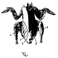
- Fig. 1 shows the muscle structure of a chicken, seen from the ventral side.
- the leg parts 2 are indicated, as well as the saddle 3.
- the saddle meat parts 5 located within the hatched areas as shown in fig. 1 .
- the saddle meat parts are different meat parts than the oyster meat or oysters that is/are sometimes mentioned in the prior art in relation to the harvesting of leg parts.
- the oyster meat or oysters is/are located on the dorsal side of the carcass, while the saddle meat parts are located on the ventral side of the carcass.
- Fig. 2 shows a detail of the left hand side of saddle meat harvester 100.
- arrow T indicates the general direction of transport of the saddles 3 or carcass parts such as back halves through the saddle meat harvester 100.
- Carcass part conveyor 150 conveys the saddles 3 or carcass parts through the saddle meat harvester.
- the carcass part conveyor is a spiked chain that engages the saddle (or engages the carcass part by the saddle) from above.
- a beam-like support 151 has been provided that supports the saddle or the carcass part while it is conveyed through the saddle meat harvester.
- Fig. 2 further shows an extension device.
- the extension device comprises a left extension guide 110 and a right extension guide (not shown).
- the shape and position of the right extension guide are the same as those of the left extension guide 110, only mirrored in a plane of symmetry that extends vertically through the central longitudinal axis of the carcass part conveyor 151.
- the extension guides 110 are horizontal, stationary guide plates that are positioned at such a height above the beam-like support 151 that they engage any saddle meat parts that cling to the rest of the carcass part, either to the saddle or to the leg parts (if leg parts are still present). As the extension guides 110 gradually extend outward in downstream directions (seen in the direction of transport T), they bring the saddle meat parts in a position in which they extend from the rest of the carcass part and no longer cling to the rest of the carcass part.
- left positioning guide 121 is arranged below the left extension guide 110.
- a right positioning guide (not shown) has been arranged on the right side of the saddle meat harvester 100.
- the shape and position of the right positioning guide are the same as those of the left positioning guide 121, only mirrored in a plane of symmetry that extends vertically through the central axis longitudinal axis of the carcass part conveyor 151.
- the positioning guides 121 are vertical, stationary guide plates.
- the part of positioning guide 121 that engages the saddle meat part is inclined relative to the path along which the carcass part conveyor 150 conveys the carcass parts or saddles.
- the positioning guides 121 extend partly below the extension guides 110.
- the positioning guides 121 engage the saddle meat parts from below and position the saddle meat parts in preparation for their separation from the saddle.
- support guides 122 are arranged downstream of the positioning guides 121. These support guides are again present on the left side as well on the right side of the saddle meat harvester.
- the support guides 122 support the saddle meat parts during the cutting of the tissue connection between the saddle meat parts and the saddle.
- the support guides 122 are vertical, stationary guide plates.
- the left positioning guide and the left support guide are integrated into single left guide plate 120. The same can optionally be done with the right positioning guide and the right support guide.
- an opening 123 is present in each support guide 122 in order to prevent scraps of meat and other tissue building up on the inside of the support guide 122 due to the cutting of the tissue connection between the saddle meat parts and the saddle.
- extension guide 110 has been extended in downstream direction with guide part 130.
- Guide part 130 preferably is present on the left side and as well as on the right side of the saddle meat harvester.
- a slot 135 extends between the extension guide 110 (including guide part 130) on the one hand and the positioning guide 121 and support guide 122 on the other hand.
- This slot 135 comprises a part that is narrower than the expected thickness of the saddle meat part in the area in which it is supported by the positioning guide and/or the support guide. Due to this, the extension guide 110,130, the positioning guide 121 and the support guide 122 exert additional friction on the saddle meat part, therewith providing a resistance force, making the slot function as a resistance element.
- the carcass part conveyor 150 continues to convey the carcass part or saddle, the tissue connection between the saddle meat part and the saddle becomes taut. This makes it easier to cut this tissue connection through and separate the saddle meat parts from the saddle.
- the slot 135 is present on the left side of the saddle meat harvester and on the right side of the saddle meat harvester.
- Fig. 3 shows the left hand side of the saddle meat harvester machine 100 including the left cutter 140. A similar cutter is present on the right side of the saddle meat harvester.
- the left cutter 140 comprises a rotatable, disc-shaped knife 141.
- the lower part of the rotary blade extends below the top edge of the support guide 122, adjacent to the slit 123.
- the extension guide 110 with guide part 130, the positioning guide 121, the support guide 122 with the opening 123, the beam-like support 151 and the carcass part conveyor 150 are all the same as in the embodiment of fig. 2 .
- the disc-shaped knife 141 is arranged under an angle relative to the vertical. This way, the cutter 140 has good access to the tissue connection between the saddle meat part and the saddle.
- the disc-shaped knife 141 extends into the slit 135 in the vicinity of the support guide 122.
- the embodiment of fig. 3 has been provided with two additional resistance elements 170, one on the left side and one on the right side of the saddle meat harvester.
- Each resistance element comprises an elastic element in the form of a rod 171 that is mounted in an elastic way to the frame of the saddle meat harvester.
- the rod 171 engages the outside surface of the positioning guide 121.
- the extension guides 110 fold the saddle meat parts away from the saddle, outward relative to the carcass part or saddle.
- the positioning guide 121 picks up the saddle meat part from below as the carcass part is moved further towards the cutters 140.
- the saddle meat part now comes to lie against the outside surface on the side of the positioning guide 121.
- the saddle meat part is forced between the rod 171 and the side surface of the positioning guide 121.
- the rod 171 exerts a resistance force on the saddle meat part, pushing it against the side surface of the positioning guide 121. This creates additional friction on the saddle meat part, which additional friction provides the resistance force.
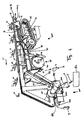
- Fig. 4 shows an overview of a first embodiment of the system according to the invention, with carriers 10 of an overhead conveyor, a leg parts harvester machine 200 and a saddle meat harvester 100.
- a back half 1 with leg parts 2 and a saddle 3 is suspended from a carrier 10, which carrier 10 engages the leg parts of the back half.
- the main direction of transport of the back halves through the system is indicated by arrow T.
- the overhead conveyor brings the back half to the leg parts harvester machine 200.
- the leg parts harvester machine 200 comprises a guide 20 that has a left side (as seen in the direction of transport) 20L and a right side (as seen in the direction of transport) 20R.
- the left side 20L of the guide 20 engages the left leg part and the right side 20R of the guide 20 engages the right leg part.
- the guide 20 widens and inclines downward in area 21. In the first, most upstream part of area 21 of the guide 20, the guide 20 acts as a disengaging guide. It disengages the leg parts 2 of the back half 1 from the carrier 10 of the overhead conveyor, such that the back half 1 is no longer carried by the carrier 10 of the overhead conveyor.
- the leg parts harvester machine further comprises a saddle conveyor, which is adapted to engage the saddle of the back half and convey it through at least the leg parts harvester machine, optionally also through the saddle meat harvester machine.
- the saddle conveyor is a set of multiple conveying devices: the support conveyor 15, the first saddle conveyor 30 and the second saddle conveyor 50.
- the support conveyor 15 supports the saddle when the incisions in the groin area and/or the back area of the back half 1 are made.
- the first saddle conveyor 30 comprises a chain with protrusions that engages the saddle 3 from above. Underneath the first saddle conveyor, saddle support guide 32 extends. The saddle support guide 32 supports the saddle 3 from below while it is transported by the first saddle conveyor 30.
- the first saddle conveyor 30 and the saddle support guide 32 have their upstream end near the disengaging guide. It is however possible as an alternative, that no support conveyor 15 is present, and instead the first saddle conveyor 30 and the saddle support guide 32 extend all the way from the point where the back halves enter the leg parts harvester machine.
- the second saddle conveyor 50 is adapted to take part in the actual separation of the leg parts 2 from the saddle 3.
- the leg parts harvester machine further comprises a groin cutter 16 which is adapted to make an incision in the groin area of the back half 1 between each leg part 2 and the saddle, 3 such that the saddle meat parts 5 remain connected to the saddle 3.
- the groin cutter comprises a left blade, which is connected to the left part 20L of the guide 20 and a right blade, which is connected to the right part 20R of the guide 20.
- the leg parts harvester machine further comprises a back cutter 35 which is adapted to make an incision between each leg part 2 and the saddle 3 in the back region of the back half.
- the back cutter 35 is used in such a way that after making the back incision, a tissue connection remains between the each leg part 2 and the saddle part 3.
- the leg parts harvester machine further comprises a leg parts separator 40, which is adapted to pull the leg parts 2 away from the saddle 3 such that the leg parts 2 are separated from the saddle 3, in such a way that the saddle meat parts 5 remain connected to the left side and/or right side of the saddle 3, the oysters preferably remaining attached to the leg parts 2.
- the leg parts separator 40 in the embodiment of fig. 4 , comprises a rotatable wheel 44 with two pairs of leg grippers 41 mounted thereon.
- the leg grippers 41 engage the leg parts 2 of a passing back half while the wheel 44 rotates about axis of rotating 43 in the direction of arrow R.
- the leg grippers 41 take the leg parts 2 of the back half with them along in their further rotation in the direction of arrow R, while the saddle 3 of that same back half is transported by the second saddle conveyor 50 and supported by saddle support guide 32.
- the speed of the leg parts 2 will be higher than the speed of the saddle 3.
- the diverging paths and the difference in speed result in a pulling force that is exerted on the leg parts 2. This pulling force causes the tissue that remained between the saddle 3 and the leg parts 2 after the incisions in the back region were made to tear. This results in a separation of the leg parts from the saddle.
- the saddle meat parts are still attached to the rest of the saddle at this moment.
- the oysters are preferably connected to the leg parts that are harvested.
- the saddle is then conveyed further to and into the saddle meat harvester 100, which is only schematically shown in fig. 4 .
- the saddle meat harvester 100 is preferably of the type described in relation to fig. 2 and fig. 3 .
- the second saddle conveyor 50 of the leg parts harvester machine has been extended with a lower chain flight 150.
- This lower chain flight 150 conveys the saddles through the saddle meat harvester 100.
- the saddles 3 are supported by the saddle support guide 132 of the saddle meat harvester 100.
- Fig. 4 schematically indicates the (left) support guide 122 and the left cutter 140. Also, a chute plate 160 for discharging the harvested saddle meat parts 5 is shown. The chute plate 160 guides the separated saddle meat parts to a saddle meat part receiving unit 180, such as a bin, a container or a conveyor belt.
- a saddle meat part receiving unit 180 such as a bin, a container or a conveyor belt.
- Fig. 5 shows a second embodiment of a system according to the invention.
- the leg parts harvester machine in the embodiment of fig. 5 works in the same way as the leg parts harvester machine in the embodiment of fig. 4 .
- the saddle meat harvester 100 is integrated into the leg parts harvester machine, and it is set up in such a way that the saddle meat parts 5 are harvested together with the leg parts 2.
- the saddle meat harvester 100 is arranged such that some processing steps in the leg part harvesting process are carried out before the saddle meat parts are separated from the saddle, and some process steps in the leg part harvesting process are carried out after saddle meat parts are separated from the saddle.
- the saddle meat harvester separates the saddle meat parts from the saddle, but a tissue connection between each saddle meat part and a leg part remains.
- the saddle meat harvester is arranged just downstream of the groin cutter.
- other positions are possible as well.
- the saddle meat harvester can be arranged entirely upstream of the leg parts harvester machine.
- al leg parts receiving unit 181 such as a bin, a container or a conveyor belt, is present to collect the harvested leg parts with the saddle meat 5 attached to them, from the leg part harvester.
Landscapes
- Life Sciences & Earth Sciences (AREA)
- Engineering & Computer Science (AREA)
- Wood Science & Technology (AREA)
- Zoology (AREA)
- Food Science & Technology (AREA)
- Processing Of Meat And Fish (AREA)
Claims (15)
- Procédé pour collecter des parties de viande de type selle d'une partie de carcasse de volaille abattue, laquelle partie de carcasse est une moitié dorsale (1) ou une partie de cette dernière,
dans lequel la partie de carcasse comprend initialement deux parties de patte (2) et une selle (3), les parties de patte (2) étant raccordées à la selle (3) via les articulations de hanche, dans lequel la partie de carcasse comprend en outre deux parties de viande de type selle, lesquelles parties de viande de type selle sont positionnées dans la région de l'aine de la partie de carcasse,
lequel le procédé comprend les étapes suivantes consistant à :séparer les parties de patte (2) des parties de viande de type selle et de la selle (3), en laissant les parties de viande de type selle raccordées à la selle (3),agencer la selle (3) dans un collecteur de viande de type selle (100), de sorte qu'une partie de viande de type selle est du côté gauche de la selle (3) et l'autre partie de viande de type selle est du côté droit de la selle (3),permettre aux parties de viande de type selle de s'étendre par rapport à la partie de carcasse, alors que les parties de viande de type selle restent raccordées à la selle (3) d'un côté de la partie viande de type selle via un raccordement de tissu,positionner le raccordement de tissu entre la partie de viande de type selle gauche et la selle (3) en alignement avec un dispositif de coupe gauche (140) et positionner le raccordement de tissu entre la partie de viande de type selle droite et la selle (3) en alignement avec un dispositif de coupe droit,déplacer la selle (3) avec les parties viande de type selle vers le dispositif de coupe gauche (140) et le dispositif de coupe droit, et pendant ce déplacement, fournir une force de résistance aux parties de viande de type selle de sorte que les raccordements de tissu entre les parties de viande de type selle et la selle (3) se tendent,couper le raccordement de tissu entre la partie de viande de type selle gauche et la selle (3) avec le dispositif de coupe gauche (140) et couper le raccordement de tissu entre la partie de viande de type selle droite et la selle (3) avec le dispositif de coupe droit, séparant avec ces derniers les parties de viande de type selle de la selle (3),ladite coupe étant initiée alors que les raccordements de tissu entre les parties de viande de type selle et la selle (3) sont tendus,collecter les parties de viande de type selle séparées. - Procédé pour collecter des parties de patte avec des parties de viande de type selle sur ces dernières d'une partie de carcasse de volaille abattue, laquelle partie de carcasse est une moitié dorsale (1) ou une partie de cette dernière,
dans lequel la partie de carcasse comprend initialement deux parties de patte et une selle (3), les parties de patte (2) étant raccordées à la selle (3) via les articulations de hanche, dans lequel la partie de carcasse comprend en outre deux parties de viande de type selle, lesquelles parties de viande de type selle sont positionnées dans la région de l'aine de la partie de carcasse,
lequel procédé comprend les étapes suivantes consistant à :agencer la partie de carcasse dans un collecteur de viande de type selle (100), de sorte qu'une partie de viande de type selle est du côté gauche de la selle (3) et l'autre partie de viande de type selle est du côté droit de la selle (3),permettre aux parties de viande de type selle de s'étendre par rapport à la partie de carcasse, alors que les parties de viande de type selle restent raccordées à la selle (3) d'un côté de la partie de viande de type selle via un raccordement de tissu,positionner le raccordement de tissu entre la partie de viande de type selle gauche et la selle (3) en alignement avec un dispositif de coupe gauche (140) et positionner le raccordement de tissu entre la partie de viande de type selle droite et la selle (3) en alignement avec un dispositif de coupe droit,déplacer la partie de carcasse avec les parties de viande de type selle vers le dispositif de coupe gauche (140) et le dispositif de coupe droit, et pendant ce déplacement, fournir une force de résistance aux parties de viande de type selle de sorte que les raccordements de tissu entre les parties de viande de type selle et la selle (3) se tendent,couper le raccordement de tissu entre la partie de viande de type selle gauche et la selle (3) avec le dispositif de coupe gauche (140) et couper le raccordement de tissu entre la partie de viande de type selle droite et la selle (3) avec le dispositif de coupe droit, séparant avec ces derniers les parties de viande de type selle de la selle (3) mais en conservant la partie de viande de type selle gauche fixée à la partie de patte gauche (2) et en conservant la partie de viande de type selle droite fixée à la partie de patte droite (2),ladite coupe étant initiée alors que les raccordements de tissu entre les parties de viande de type selle et la selle (3) sont tendus,séparer les parties de patte (2) de la selle (3) tout en conservant la partie de viande de type selle gauche fixée à la partie de patte gauche (2) et en conservant la partie de viande de type selle droite fixée à la partie de patte droite (2),collecter les parties de patte (2) séparées avec les parties de viande de type selle fixées à ces dernières. - Procédé selon l'une quelconque des revendications précédentes :dans lequel les parties de viande de type selle s'étendent par rapport à la partie de carcasse par un guide d'extension (110) ou par des rouleaux d'extension ou par les brosses ou sous l'influence de la gravité, et/oudans lequel le raccordement de tissu entre la partie de viande de type selle et la selle (3) est positionné par un guide de positionnement gauche (121) et le raccordement de tissu entre la partie de viande de type selle droite et la selle (3) est positionné par un guide de positionnement droit, et/oudans lequel les parties de viande de type selle sont supportées par un guide de support (122) pendant la coupe du raccordement de tissu entre les parties de viande de type selle et la selle (3).
- Procédé selon la revendication 3,
dans lequel la force de résistance sur une partie de viande de type selle est obtenue en déplaçant les parties de viande de type selle à travers une fente (135) entre le guide de positionnement (121) et le guide d'extension (110) et/ou entre le guide d'extension (110) et le guide de support (122) si un guide de support (122) est présent, laquelle fente (135) est plus étroite que l'épaisseur attendue des parties de viande de type selle dans la zone qui est mise en prise par le guide de positionnement (121). - Procédé selon l'une quelconque des revendications précédentes,
dans lequel la force de résistance sur une partie de viande de type selle est obtenue par un élément élastique (171), dans lequel facultativement l'élément élastique pousse la partie de viande de type selle contre le guide de positionnement (121) et/ou le guide d'extension (110) et/ou le guide de support (122). - Procédé selon l'une quelconque des revendications précédentes,
dans lequel le procédé comprend en outre les étapes suivantes consistant à :transporter les parties de carcasse le long d'une trajectoire dans un convoyeur principal, lequel convoyeur principal comprend une pluralité de supports (10), un support (10) mettant en prise une partie de carcasse par ou à proximité des extrémités libres des parties de patte (2) de sorte que la partie de carcasse est suspendue au support (10) par les extrémités libres des parties de patte (2) orientées vers le haut,déboîter les articulations de hanche de sorte qu'un raccordement de tissu reste entre chaque partie de patte (2) et la selle (3),dégager les parties de patte (2) du support (10) du convoyeur principal, permettant ainsi aux extrémités libres des parties de patte (2) d'être orientées vers le bas,après avoir dégagé les parties de patte (2) du support (10) du convoyeur principal, supporter la selle (3),saisir chaque partie de patte (2) à l'aide d'un séparateur de patte (40) avec un dispositif de préhension de patte (41), chaque dispositif de préhension de patte (41) ayant une fente de préhension de patte pour mettre en prise une partie de patte (2),séparer les parties de patte (2) de la selle (3) en exerçant un mouvement de traction sur les parties de patte (2) par rapport à la selle (3), détachant ainsi par déchirement le raccordement de tissu entre chaque partie de patte (2) et la selle (3) de sorte que les parties de patte (2) se séparent de la selle (3). - Procédé selon l'une quelconque des revendications 1 à 5,
dans lequel la partie de carcasse à traiter est une moitié dorsale (1) et dans lequel le procédé comprend en outre les étapes suivantes consistant à :agencer la moitié dorsale (1) dans un support (10) d'un convoyeur en hauteur de sorte que la moitié dorsale (1) est suspendue au support (10), le support (10) mettant en prise la partie de carcasse par les parties de patte (2) de sorte que les parties de patte (2) sont orientées vers le haut,transporter la moitié dorsale (1) par le convoyeur en hauteur vers une machine de collecte de parties de patte (200),dans la machine de collecte de parties de patte (200), dégager la moitié dorsale (1) du support (10) du convoyeur en hauteur et continuer à transporter la moitié dorsale (1) dans la machine de collecte de parties de patte (200) grâce à un convoyeur de selle (15, 30, 50),dans la machine de collecte de parties de patte (200), pratiquer une incision dans la région de l'aine de la moitié dorsale (1) entre chaque partie de patte (2) et la selle (3), de sorte que les parties de viande de type selle restent raccordées à la selle (3),dans la machine de collecte de parties de patte (200), déboîter les articulations de hanche,dans la machine de collecte de parties de patte (200), pratiquer une incision entre chaque partie de patte (2) et la selle (3) dans la région dorsale de la partie de carcasse en utilisant un dispositif de coupe pour le dos (35) de sorte qu'après avoir pratiqué l'incision postérieure, un raccordement de tissu reste entre chaque partie de patte (2) et la partie de viande de type selle,dans la machine de collecte de parties de patte (200), écarter les parties de patte (2) de la selle (3) de sorte que les parties de patte (2) sont séparées de la selle (3), de sorte que les parties de viande de type selle restent raccordées au côté gauche et/ou au côté droit de la selle (3), les sot-l' y-laisse restant de préférence fixés aux parties de patte (2), transporter la selle (3) grâce au convoyeur de selle (15, 30, 50) vers un collecteur de viande de type selle (100). - Procédé selon la revendication 6 ou la revendication 7,
dans lequel l'écartement des parties de patte (2) de la selle (3) de sorte que les parties de patte (2) sont séparées de la selle (3), est une traction vers le bas. - Système pour collecter des parties de viande de type selle d'une partie de carcasse de volaille abattue, laquelle partie de carcasse est une moitié dorsale (1) ou une partie de cette dernière,
dans lequel la partie de carcasse comprend initialement deux parties de patte et une selle (3), les parties de patte (2) étant raccordées à la selle (3) via les articulations de hanche, dans lequel la partie de carcasse comprend en outre deux parties de viande de type selle, lesquelles parties de viande de type selle sont positionnées dans la région de l'aine de la partie de carcasse,
lequel système comprend :une machine de collecte de parties de patte (200) pour séparer les parties de patte (2) des parties de viande de type selle et la selle (3), laissant les parties de viande de type selle raccordées à la selle (3),un collecteur de viande de type selle (100) pour collecter les parties de viande de type selle, lequel collecteur de viande de type selle (100) est adapté pour recevoir les parties de carcasse avec une partie de viande de type selle du côté gauche de la selle (3) et l'autre partie de viande de type selle du côté droit de la selle (3), lequel collecteur de viande de type selle (100) est agencé en aval de la machine de collecte de parties de patte (200),lequel collecteur de viande de type selle (100) comprend :un dispositif d'extension (100) pour permettre aux parties de viande de type selle de s'étendre par rapport à la partie de carcasse, alors que les parties de viande de type selle restent raccordées à la selle (3) d'un côté de la partie de viande de type selle via un raccordement de tissu,un dispositif de coupe gauche (140) pour couper le raccordement de tissu entre la partie de viande de type selle gauche et la selle (3) et un dispositif de coupe droit pour couper le raccordement de tissu entre la partie de viande de type selle droite et la selle (3),un guide de positionnement gauche (121) pour positionner le raccordement de tissu entre la partie de viande de type selle gauche et la selle (3) en alignement avec le dispositif de coupe gauche (140) et un guide de positionnement droit pour positionner le raccordement de tissu entre la partie de viande de type selle et la selle (3) en alignement avec le dispositif de coupe droit,un convoyeur de partie de carcasse (150) pour déplacer la partie de carcasse avec les parties de viande de type selle vers le dispositif de coupe gauche (140) et le dispositif de coupe droit,un élément de résistance (170) pour fournir une force de résistance aux parties de viande de type selle pendant le transport de la partie de carcasse avec les parties de viande de type selle par le convoyeur de partie de carcasse (150), de sorte que les raccordements de tissu entre les parties de viande de type selle et la selle (3) se tendent,ledit élément de résistance (170) étant positionné par rapport au dispositif de coupe gauche (140) et au dispositif de coupe droit de sorte que la coupe des raccordements de tissu entre les parties de viande de type selle et la selle (3) est initiée alors que les raccordements de tissu entre les parties de viande de type selle et la selle (3) sont tendus,une unité de réception de viande de type selle pour collecter les parties de viande de type selle séparées. - Système pour collecter des parties de patte avec des parties de viande de type selle sur ces dernières d'une partie de carcasse de volaille abattue, laquelle partie de carcasse est une moitié dorsale (1) ou une partie de cette dernière,
dans lequel la partie de carcasse comprend initialement deux parties de patte et une selle (3), les parties de patte (2) étant raccordées à la selle (3) via les articulations de hanche, dans lequel la partie de carcasse comprend en outre deux parties de viande de type selle, lesquelles parties de viande de type selle sont positionnées dans la région de l'aine de la partie de carcasse,
lequel système comprend :un collecteur de viande de type selle (100) pour collecter les parties de viande de type selle, lequel collecteur de viande de type selle (100) est adapté pour recevoir les parties de carcasse avec une partie de viande de type selle du côté gauche de la selle (3) et l'autre partie de viande de type selle du côté droit de la selle (3),lequel collecteur de viande de type selle (100) comprend :un dispositif d'extension (110) pour permettre aux parties de viande de type selle de s'étendre par rapport à la partie de carcasse, alors que lesdites parties de viande de type selle restent raccordées à la selle (3) d'un côté de la partie de viande de type selle via un raccordement de tissu,un guide de positionnement gauche (121) pour positionner le raccordement de tissu entre la partie de viande de type selle gauche et la selle (3) en alignement avec un dispositif de coupe gauche (140) et un guide de positionnement droit pour positionner le raccordement de tissu entre la partie de viande de type selle droite et la selle (3) en alignement avec un dispositif de coupe droit,un convoyeur de partie de carcasse (150) pour déplacer la partie de carcasse avec les parties de viande de type selle vers le dispositif de coupe gauche (140) et le dispositif de coupe droit,un élément de résistance (170) pour fournir une force de résistance aux parties de viande de type selle pendant le transport de la partie de carcasse avec les parties de viande de type selle par le convoyeur de partie de carcasse (150), de sorte que les raccordements de tissu entre les parties de viande de type selle et la selle (3) se tendent,ledit élément de résistance (170) étant positionné par rapport au dispositif de coupe gauche (140) et au dispositif de coupe droit de sorte que la coupe des raccordements de tissu entre les parties de viande de type selle et la selle (3) est initiée alors que les raccordements de tissu entre les parties de viande de type selle et la selle (3) sont tendus,une machine de collecte de parties de patte (200) pour séparer les parties de patte (2) de la selle (3) tout en conservant la partie de viande de type selle gauche fixée à la partie de patte gauche (2) et en conservant la partie de viande de type selle droite fixée à la partie de patte droite (2), laquelle machine de collecte de parties de patte (200) est agencée en aval du collecteur de viande de type selle (100),une unité de réception de parties de patte pour collecter les parties de patte (2) séparées avec les parties de viande de type selle fixées à ces dernières. - Système selon l'une quelconque des revendications 9 à 10,
dans lequel le système comprend en outre un guide de support (122) pour supporter les parties de viande de type selle pendant la coupe du raccordement de tissu entre les parties de viande de type selle et la selle (3),
lequel guide de support (122) comprend de préférence une partie de guidage de support gauche et une partie de guidage de support droite, la partie de guidage de support gauche étant adaptée pour supporter la partie de viande de type selle gauche pendant la coupe et la partie de guidage de support droite étant adaptée pour supporter la partie de viande de type selle droite pendant la coupe, dans lequel facultativement le guide de positionnement gauche (121) est raccordé à la partie de guidage de support gauche et le guide de positionnement droit est raccordé à la partie de guidage de support droite. - Système selon l'une quelconque des revendications 9 à 11,
dans lequel l'élément de résistance (170) est une fente (135) entre le guide de positionnement (121) et le guide d'extension (110) et/ou entre le guide d'extension (110) et le guide de support (122) si un guide de support (122) est présent, laquelle fente (135) est plus étroite que l'épaisseur attendue des parties de viande de type selle dans la zone qui est mise en prise par le guide de positionnement (121), et/ou
dans lequel l'élément de résistance (170) est un élément élastique, dans lequel facultativement l'élément élastique est adapté pour pousser la partie de viande de type selle contre le guide de positionnement (121) et/ou le guide d'extension (110) et/ou le guide de support (122). - Système selon l'une quelconque des revendications 9 à 12,
dans lequel le système comprend en outre :un convoyeur principal, lequel convoyeur principal comprend une pluralité de supports (10), chaque support (10) étant adapté pour mettre en prise une partie de carcasse par ou à proximité des extrémités libres des parties de patte (2) de sorte que la partie de carcasse est suspendue au support (10) avec les extrémités libres des parties de patte orientées vers le haut,le convoyeur principal étant prévu avec un entraînement pour déplacer les supports (10) le long d'une trajectoire,dans la machine de collecte de parties de patte (200), un ensemble de déboîtement de hanche, qui est adapté pour déboîter les articulations de hanche de sorte qu'après ledit déboîtement, un raccordement de tissu reste entre chaque partie de patte (2) et la selle (3), et adapté pour dégager les parties de patte (2) du support (10) du convoyeur principal de sorte que les extrémités libres des parties de patte (2) sont orientées vers le bas,dans la machine de collecte de parties de patte (200), un guide de support de selle (32), qui est adapté pour supporter la selle (3) de la partie de carcasse après que la partie de carcasse a été dégagée du support (10) du convoyeur principal,dans la machine de collecte de parties de patte (200), un séparateur de patte (40) comprenant deux dispositifs de préhension de patte (41), chaque dispositif de préhension de patte (41) comprenant une fente de préhension de patte qui est adaptée pour mettre en prise une partie de patte (2),dans lequel les dispositifs de préhension de patte (41) sont adaptés pour induire un mouvement de traction des parties de patte (2) par rapport à la selle (3), détachant ainsi par déchirement le raccordement de tissu entre chaque partie de patte (2) et la selle (3), de sorte que les parties de patte (2) sont séparées de la selle (3),le séparateur de patte (40) étant agencé par rapport au guide de support de selle (32) de sorte que le guide de support de selle (32) supporte la selle (3) pendant la préhension et la traction des parties de patte (2). - Système selon l'une quelconque des revendications 9 à 12,
dans lequel la partie de carcasse à traiter est une moitié dorsale (1),
dans lequel le système comprend en outre :un convoyeur en hauteur comprenant une pluralité de supports (10), chaque support (10) étant adapté pour mettre en prise les parties de patte (2) d'une moitié dorsale (1), de sorte que la moitié dorsale (1) est suspendue au support (10), les supports (10) étant mobiles le long d'une voie,et dans lequel la machine de collecte de parties de patte (200) comprend :un guide de dégagement, qui est adapté pour dégager les parties de patte (2) de la moitié dorsale (1) du support (10) du convoyeur en hauteur, de sorte que la moitié dorsale (1) n'est plus supportée par le support (10) du convoyeur en hauteur,un convoyeur de selle (15, 30, 50) qui est adapté pour mettre en prise la selle (3) de la moitié dorsale (1) et la transporter au moins dans la machine de collecte de parties de patte (200), facultativement également dans le collecteur de viande de type selle (100),un dispositif de coupe de région de l'aine (16) qui est adapté pour pratiquer une incision dans la région de l'aine de la moitié dorsale (1) entre chaque partie de patte (2) et la selle (3), de sorte que les parties de viande de type selle restent raccordées à la selle (3),un guide de déboîtement de hanche qui est adapté pour déboîter les articulations de hanche,un dispositif de coupe de dos (35) qui est adapté pour pratiquer une incision entre chaque partie de patte (2) et la selle (3) dans la région de dos de la partie de carcasse de sorte qu'après avoir pratiqué une incision dorsale, un raccordement de tissu reste entre chaque partie de patte (2) et la partie de viande de type selle,un séparateur de parties de patte (40) qui est adapté pour écarter les parties de patte (2) de la selle (3) de sorte que les parties de patte (2) sont séparées de la selle (3), de façon à ce que les parties de viande de type selle restent raccordées au côté gauche et/ou le côté droit de la selle (3). - Système selon l'une quelconque des revendications 13 à 14,
dans lequel le séparateur de parties de patte (40) est agencé de sorte que la traction des parties de patte (2) afin de les séparer de la selle (3) est une traction descendante.
Applications Claiming Priority (2)
| Application Number | Priority Date | Filing Date | Title |
|---|---|---|---|
| NL2009646A NL2009646C2 (en) | 2012-10-17 | 2012-10-17 | System and method for harvesting saddle meat from a carcass part of slaughtered poultry. |
| PCT/NL2013/050713 WO2014062053A1 (fr) | 2012-10-17 | 2013-10-09 | Système et procédé de collecte de viande de type selle à partir d'une partie carcasse de volailles abattues |
Publications (2)
| Publication Number | Publication Date |
|---|---|
| EP2908649A1 EP2908649A1 (fr) | 2015-08-26 |
| EP2908649B1 true EP2908649B1 (fr) | 2016-05-25 |
Family
ID=47222252
Family Applications (1)
| Application Number | Title | Priority Date | Filing Date |
|---|---|---|---|
| EP13777160.6A Active EP2908649B1 (fr) | 2012-10-17 | 2013-10-09 | Système et procédé de collecte de viande de type selle à partir d'une partie carcasse de volailles abattues |
Country Status (9)
| Country | Link |
|---|---|
| US (2) | US9375019B2 (fr) |
| EP (1) | EP2908649B1 (fr) |
| JP (1) | JP6266003B2 (fr) |
| CN (1) | CN204969171U (fr) |
| BR (1) | BR112015008104B1 (fr) |
| DK (1) | DK2908649T3 (fr) |
| ES (1) | ES2582778T3 (fr) |
| NL (1) | NL2009646C2 (fr) |
| WO (1) | WO2014062053A1 (fr) |
Cited By (1)
| Publication number | Priority date | Publication date | Assignee | Title |
|---|---|---|---|---|
| US9801394B2 (en) | 2015-10-22 | 2017-10-31 | Baader Linco, Inc. | Separation tool |
Families Citing this family (9)
| Publication number | Priority date | Publication date | Assignee | Title |
|---|---|---|---|---|
| NL2009647C2 (en) | 2012-10-17 | 2014-04-22 | Marel Stork Poultry Proc Bv | Device for separating a leg part from a carcass part of slaughtered poultry. |
| NL2009646C2 (en) | 2012-10-17 | 2014-04-22 | Marel Stork Poultry Proc Bv | System and method for harvesting saddle meat from a carcass part of slaughtered poultry. |
| NL2016723B1 (en) * | 2016-05-03 | 2017-11-10 | Marel Stork Poultry Proc Bv | Back meat harvester for harvesting back meat from a carcass part of slaughtered poultry |
| US10201167B2 (en) | 2016-12-28 | 2019-02-12 | Campbell Soup Company | Systems and methods for producing irregular meat chunks |
| NL2019364B1 (en) * | 2017-07-28 | 2019-02-19 | Meyn Food Processing Tech Bv | Scapula harvester for operating on a poultry carcass |
| DE102020108616B4 (de) * | 2020-03-27 | 2022-05-25 | Nordischer Maschinenbau Rud. Baader Gmbh + Co. Kg | Vorrichtung und Verfahren zum Gewinnen des inneren Rückenfleisches von Geflügel |
| DE102020108618A1 (de) | 2020-03-27 | 2021-09-30 | Nordischer Maschinenbau Rud. Baader Gmbh + Co. Kg | Halteelement zum Anordnen von Rückenteilen oder Teilen davon von Geflügelschlachtkörpern |
| NL2027154B1 (en) * | 2020-12-18 | 2022-07-13 | Marel Poultry B V | A system and method for processing a backhalve of a slaughtered poultry carcass. |
| NL2028710B1 (en) * | 2021-07-13 | 2023-01-18 | Marel Poultry B V | System and method for processing a carcass part |
Family Cites Families (26)
| Publication number | Priority date | Publication date | Assignee | Title |
|---|---|---|---|---|
| NL8204464A (nl) * | 1982-11-18 | 1984-06-18 | Stork Pmt | Werkwijze en inrichting voor het in stukken verdelen van geslacht gevogelte. |
| NL8401122A (nl) * | 1984-04-09 | 1985-11-01 | Stork Pmt | Inrichting voor het afscheiden van de staartstomp van geslacht gevogelte. |
| NL8800004A (nl) * | 1988-01-05 | 1989-08-01 | Meyn Maschf | Inrichting voor het in delen snijden van de vleugels van gevogelte. |
| US5015213A (en) * | 1990-01-31 | 1991-05-14 | Hazenbroek Jacobus E | On-line cut-up system with joint opener |
| US5045022A (en) * | 1990-01-31 | 1991-09-03 | Hazenbroek Jacobus E | Adjustable poultry breast filleting system |
| US5035673A (en) * | 1990-01-31 | 1991-07-30 | Hazenbroek Jacobus R | On-line breast halver |
| NL9001246A (nl) | 1990-05-31 | 1991-12-16 | Stork Pmt | Werkwijze en inrichting voor het van een rompdeel scheiden van de poten van geslacht gevogelte. |
| US5188559A (en) | 1991-09-16 | 1993-02-23 | Hazenbroek Jacobus E | Method and apparatus for separating the legs from the back of a poultry carcass |
| NL9200037A (nl) * | 1992-01-10 | 1993-08-02 | Stork Pmt | Werkwijze en inrichting voor het fileren van de romp van een geslachte vogel. |
| US5194035A (en) | 1992-01-17 | 1993-03-16 | Meyn Usa, Inc. | Automatic poultry processor and method |
| US5336127A (en) * | 1992-09-22 | 1994-08-09 | Hazenbroek Jacobus E | Method and apparatus for centrally aligning and cutting the keel bone of a poultry carcass |
| DE4304781C1 (de) * | 1993-02-17 | 1994-09-22 | Nordischer Maschinenbau | Verfahren zum Abtrennen der Flügel von Geflügelkörpern |
| NL9400954A (nl) | 1994-06-13 | 1996-01-02 | Stork Protecon Langen Bv | Inrichting voor het ontbenen van vleesstukken met een samengesteld beenstelsel. |
| US5429549A (en) * | 1994-10-05 | 1995-07-04 | Systemate Holland, B.V. | Sequential wing remover |
| BR9800345A (pt) * | 1997-01-21 | 1999-06-29 | Nordischer Maschinenbau | Instalação para a separação das pernas de corpos de aves |
| DE69820279T2 (de) | 1997-09-29 | 2004-05-27 | Stork Pmt B.V. | Verfahren und vorrichtung zum einschneiden der haut von schlachtgeflügel und zur durchführung einer subkutanen operation |
| NL1012703C2 (nl) | 1999-04-06 | 2000-10-09 | Stork Pmt | Werkwijze en inrichting voor het bewerken van een gevogeltepoot. |
| US6322438B1 (en) * | 1999-07-15 | 2001-11-27 | Systemate Group, B.V. | Poultry leg and thigh processor |
| WO2004112489A1 (fr) * | 2003-06-20 | 2004-12-29 | Mayekawa Mfg.Co., Ltd. | Procede pour separer le sot-l'y-laisse de la cuisse et dispositif utilise a cet effet |
| NL1023752C2 (nl) | 2003-06-26 | 2004-12-28 | Meyn Food Proc Technology Bv | Inrichting voor het automatisch verwijderen van een staart van gevogelte. |
| US20050059334A1 (en) * | 2003-09-12 | 2005-03-17 | Tyson Foods, Inc. | Leg processor yield improvement |
| NL2003384C2 (en) * | 2009-08-24 | 2011-02-28 | Meijn Food Proc Technology B V | Method and device for processing a carcass-part of slaughtered poultry. |
| WO2011121899A1 (fr) | 2010-03-30 | 2011-10-06 | Mayekawa Mfg. Co., Ltd. | Procédé et dispositif pour le désossage d'une jambe non désossée |
| NL2008729C2 (en) * | 2012-04-27 | 2013-10-29 | Meyn Food Proc Technology Bv | A method and apparatus for processing a poultry carcass part. |
| NL2009646C2 (en) | 2012-10-17 | 2014-04-22 | Marel Stork Poultry Proc Bv | System and method for harvesting saddle meat from a carcass part of slaughtered poultry. |
| NL2009647C2 (en) | 2012-10-17 | 2014-04-22 | Marel Stork Poultry Proc Bv | Device for separating a leg part from a carcass part of slaughtered poultry. |
-
2012
- 2012-10-17 NL NL2009646A patent/NL2009646C2/en not_active IP Right Cessation
-
2013
- 2013-10-09 ES ES13777160.6T patent/ES2582778T3/es active Active
- 2013-10-09 JP JP2015537655A patent/JP6266003B2/ja active Active
- 2013-10-09 CN CN201390000816.3U patent/CN204969171U/zh not_active Expired - Lifetime
- 2013-10-09 DK DK13777160.6T patent/DK2908649T3/en active
- 2013-10-09 BR BR112015008104-5A patent/BR112015008104B1/pt active IP Right Grant
- 2013-10-09 EP EP13777160.6A patent/EP2908649B1/fr active Active
- 2013-10-09 WO PCT/NL2013/050713 patent/WO2014062053A1/fr not_active Ceased
- 2013-10-09 US US14/436,560 patent/US9375019B2/en active Active
-
2015
- 2015-07-10 US US14/796,211 patent/US9320287B2/en active Active
Non-Patent Citations (1)
| Title |
|---|
| None * |
Cited By (2)
| Publication number | Priority date | Publication date | Assignee | Title |
|---|---|---|---|---|
| US9801394B2 (en) | 2015-10-22 | 2017-10-31 | Baader Linco, Inc. | Separation tool |
| US10165783B2 (en) | 2015-10-22 | 2019-01-01 | Baader Linco, Inc. | Poultry carcass processing method |
Also Published As
| Publication number | Publication date |
|---|---|
| ES2582778T3 (es) | 2016-09-15 |
| NL2009646C2 (en) | 2014-04-22 |
| EP2908649A1 (fr) | 2015-08-26 |
| CN204969171U (zh) | 2016-01-20 |
| US9320287B2 (en) | 2016-04-26 |
| BR112015008104A2 (pt) | 2017-07-04 |
| JP2015532117A (ja) | 2015-11-09 |
| WO2014062053A1 (fr) | 2014-04-24 |
| JP6266003B2 (ja) | 2018-01-24 |
| US9375019B2 (en) | 2016-06-28 |
| US20150313246A1 (en) | 2015-11-05 |
| US20150296814A1 (en) | 2015-10-22 |
| DK2908649T3 (en) | 2016-08-29 |
| BR112015008104B1 (pt) | 2020-12-01 |
Similar Documents
| Publication | Publication Date | Title |
|---|---|---|
| EP2908649B1 (fr) | Système et procédé de collecte de viande de type selle à partir d'une partie carcasse de volailles abattues | |
| EP2353396B1 (fr) | Procédé et dispositif de traitement d'une pièce de carcasse de volaille abattue | |
| EP2908650B1 (fr) | Dispositif pour séparer une partie de patte d'une partie de carcasse de volaille abattue | |
| US6322438B1 (en) | Poultry leg and thigh processor | |
| CA2008386C (fr) | Separateur reglable de carcasse de volaille | |
| US5154665A (en) | On-line poultry thigh remover | |
| US7967668B2 (en) | Method and apparatus for the separate harvesting of back skin and back meat from a carcass part of slaughtered poultry | |
| CN106604642B (zh) | 用于从家禽腿采集膝肉连同大腿肉的方法和系统 | |
| EP2704581B1 (fr) | Appareil pour récupérer la viande du cou des volailles et procédé pour la récupération mecanisée de la viande du cou des volailles | |
| EP2724618B1 (fr) | Procédé et système pour enlever automatiquement la viande d'une extrémité d'un animal | |
| US8430728B2 (en) | Special cut poultry wing cutter | |
| EP2911520B1 (fr) | Procédé d'élimination mécanique de la peau de parties animales | |
| US10477872B1 (en) | Method and apparatus for removing wings from a poultry carcass | |
| KR20180053324A (ko) | 가금류의 브레스트 캡들로부터 창사골을 제거하기 위한 장치, 시스템 및 방법 | |
| US8727839B2 (en) | Poultry wing cutter for narrow pitch poultry lines |
Legal Events
| Date | Code | Title | Description |
|---|---|---|---|
| PUAI | Public reference made under article 153(3) epc to a published international application that has entered the european phase |
Free format text: ORIGINAL CODE: 0009012 |
|
| 17P | Request for examination filed |
Effective date: 20150513 |
|
| AK | Designated contracting states |
Kind code of ref document: A1 Designated state(s): AL AT BE BG CH CY CZ DE DK EE ES FI FR GB GR HR HU IE IS IT LI LT LU LV MC MK MT NL NO PL PT RO RS SE SI SK SM TR |
|
| AX | Request for extension of the european patent |
Extension state: BA ME |
|
| DAX | Request for extension of the european patent (deleted) | ||
| GRAP | Despatch of communication of intention to grant a patent |
Free format text: ORIGINAL CODE: EPIDOSNIGR1 |
|
| INTG | Intention to grant announced |
Effective date: 20160311 |
|
| GRAS | Grant fee paid |
Free format text: ORIGINAL CODE: EPIDOSNIGR3 |
|
| GRAA | (expected) grant |
Free format text: ORIGINAL CODE: 0009210 |
|
| AK | Designated contracting states |
Kind code of ref document: B1 Designated state(s): AL AT BE BG CH CY CZ DE DK EE ES FI FR GB GR HR HU IE IS IT LI LT LU LV MC MK MT NL NO PL PT RO RS SE SI SK SM TR |
|
| REG | Reference to a national code |
Ref country code: GB Ref legal event code: FG4D |
|
| REG | Reference to a national code |
Ref country code: CH Ref legal event code: EP |
|
| REG | Reference to a national code |
Ref country code: IE Ref legal event code: FG4D Ref country code: AT Ref legal event code: REF Ref document number: 801464 Country of ref document: AT Kind code of ref document: T Effective date: 20160615 |
|
| REG | Reference to a national code |
Ref country code: NL Ref legal event code: FP |
|
| REG | Reference to a national code |
Ref country code: DE Ref legal event code: R096 Ref document number: 602013008086 Country of ref document: DE |
|
| REG | Reference to a national code |
Ref country code: DK Ref legal event code: T3 Effective date: 20160828 |
|
| REG | Reference to a national code |
Ref country code: ES Ref legal event code: FG2A Ref document number: 2582778 Country of ref document: ES Kind code of ref document: T3 Effective date: 20160915 |
|
| REG | Reference to a national code |
Ref country code: LT Ref legal event code: MG4D |
|
| REG | Reference to a national code |
Ref country code: FR Ref legal event code: PLFP Year of fee payment: 4 |
|
| PG25 | Lapsed in a contracting state [announced via postgrant information from national office to epo] |
Ref country code: LT Free format text: LAPSE BECAUSE OF FAILURE TO SUBMIT A TRANSLATION OF THE DESCRIPTION OR TO PAY THE FEE WITHIN THE PRESCRIBED TIME-LIMIT Effective date: 20160525 Ref country code: FI Free format text: LAPSE BECAUSE OF FAILURE TO SUBMIT A TRANSLATION OF THE DESCRIPTION OR TO PAY THE FEE WITHIN THE PRESCRIBED TIME-LIMIT Effective date: 20160525 Ref country code: NO Free format text: LAPSE BECAUSE OF FAILURE TO SUBMIT A TRANSLATION OF THE DESCRIPTION OR TO PAY THE FEE WITHIN THE PRESCRIBED TIME-LIMIT Effective date: 20160825 |
|
| REG | Reference to a national code |
Ref country code: AT Ref legal event code: MK05 Ref document number: 801464 Country of ref document: AT Kind code of ref document: T Effective date: 20160525 |
|
| PG25 | Lapsed in a contracting state [announced via postgrant information from national office to epo] |
Ref country code: RS Free format text: LAPSE BECAUSE OF FAILURE TO SUBMIT A TRANSLATION OF THE DESCRIPTION OR TO PAY THE FEE WITHIN THE PRESCRIBED TIME-LIMIT Effective date: 20160525 Ref country code: SE Free format text: LAPSE BECAUSE OF FAILURE TO SUBMIT A TRANSLATION OF THE DESCRIPTION OR TO PAY THE FEE WITHIN THE PRESCRIBED TIME-LIMIT Effective date: 20160525 Ref country code: LV Free format text: LAPSE BECAUSE OF FAILURE TO SUBMIT A TRANSLATION OF THE DESCRIPTION OR TO PAY THE FEE WITHIN THE PRESCRIBED TIME-LIMIT Effective date: 20160525 Ref country code: GR Free format text: LAPSE BECAUSE OF FAILURE TO SUBMIT A TRANSLATION OF THE DESCRIPTION OR TO PAY THE FEE WITHIN THE PRESCRIBED TIME-LIMIT Effective date: 20160826 Ref country code: PT Free format text: LAPSE BECAUSE OF FAILURE TO SUBMIT A TRANSLATION OF THE DESCRIPTION OR TO PAY THE FEE WITHIN THE PRESCRIBED TIME-LIMIT Effective date: 20160926 |
|
| PG25 | Lapsed in a contracting state [announced via postgrant information from national office to epo] |
Ref country code: CZ Free format text: LAPSE BECAUSE OF FAILURE TO SUBMIT A TRANSLATION OF THE DESCRIPTION OR TO PAY THE FEE WITHIN THE PRESCRIBED TIME-LIMIT Effective date: 20160525 Ref country code: SK Free format text: LAPSE BECAUSE OF FAILURE TO SUBMIT A TRANSLATION OF THE DESCRIPTION OR TO PAY THE FEE WITHIN THE PRESCRIBED TIME-LIMIT Effective date: 20160525 Ref country code: RO Free format text: LAPSE BECAUSE OF FAILURE TO SUBMIT A TRANSLATION OF THE DESCRIPTION OR TO PAY THE FEE WITHIN THE PRESCRIBED TIME-LIMIT Effective date: 20160525 Ref country code: EE Free format text: LAPSE BECAUSE OF FAILURE TO SUBMIT A TRANSLATION OF THE DESCRIPTION OR TO PAY THE FEE WITHIN THE PRESCRIBED TIME-LIMIT Effective date: 20160525 |
|
| PG25 | Lapsed in a contracting state [announced via postgrant information from national office to epo] |
Ref country code: SM Free format text: LAPSE BECAUSE OF FAILURE TO SUBMIT A TRANSLATION OF THE DESCRIPTION OR TO PAY THE FEE WITHIN THE PRESCRIBED TIME-LIMIT Effective date: 20160525 Ref country code: AT Free format text: LAPSE BECAUSE OF FAILURE TO SUBMIT A TRANSLATION OF THE DESCRIPTION OR TO PAY THE FEE WITHIN THE PRESCRIBED TIME-LIMIT Effective date: 20160525 Ref country code: PL Free format text: LAPSE BECAUSE OF FAILURE TO SUBMIT A TRANSLATION OF THE DESCRIPTION OR TO PAY THE FEE WITHIN THE PRESCRIBED TIME-LIMIT Effective date: 20160525 Ref country code: BE Free format text: LAPSE BECAUSE OF FAILURE TO SUBMIT A TRANSLATION OF THE DESCRIPTION OR TO PAY THE FEE WITHIN THE PRESCRIBED TIME-LIMIT Effective date: 20160525 |
|
| REG | Reference to a national code |
Ref country code: DE Ref legal event code: R097 Ref document number: 602013008086 Country of ref document: DE |
|
| PLBE | No opposition filed within time limit |
Free format text: ORIGINAL CODE: 0009261 |
|
| STAA | Information on the status of an ep patent application or granted ep patent |
Free format text: STATUS: NO OPPOSITION FILED WITHIN TIME LIMIT |
|
| 26N | No opposition filed |
Effective date: 20170228 |
|
| PG25 | Lapsed in a contracting state [announced via postgrant information from national office to epo] |
Ref country code: SI Free format text: LAPSE BECAUSE OF FAILURE TO SUBMIT A TRANSLATION OF THE DESCRIPTION OR TO PAY THE FEE WITHIN THE PRESCRIBED TIME-LIMIT Effective date: 20160525 |
|
| REG | Reference to a national code |
Ref country code: CH Ref legal event code: PL |
|
| REG | Reference to a national code |
Ref country code: IE Ref legal event code: MM4A |
|
| PG25 | Lapsed in a contracting state [announced via postgrant information from national office to epo] |
Ref country code: CH Free format text: LAPSE BECAUSE OF NON-PAYMENT OF DUE FEES Effective date: 20161031 Ref country code: LI Free format text: LAPSE BECAUSE OF NON-PAYMENT OF DUE FEES Effective date: 20161031 |
|
| PG25 | Lapsed in a contracting state [announced via postgrant information from national office to epo] |
Ref country code: LU Free format text: LAPSE BECAUSE OF NON-PAYMENT OF DUE FEES Effective date: 20161009 |
|
| REG | Reference to a national code |
Ref country code: FR Ref legal event code: PLFP Year of fee payment: 5 |
|
| PG25 | Lapsed in a contracting state [announced via postgrant information from national office to epo] |
Ref country code: IE Free format text: LAPSE BECAUSE OF NON-PAYMENT OF DUE FEES Effective date: 20161009 |
|
| PG25 | Lapsed in a contracting state [announced via postgrant information from national office to epo] |
Ref country code: HU Free format text: LAPSE BECAUSE OF FAILURE TO SUBMIT A TRANSLATION OF THE DESCRIPTION OR TO PAY THE FEE WITHIN THE PRESCRIBED TIME-LIMIT; INVALID AB INITIO Effective date: 20131009 |
|
| PG25 | Lapsed in a contracting state [announced via postgrant information from national office to epo] |
Ref country code: IS Free format text: LAPSE BECAUSE OF FAILURE TO SUBMIT A TRANSLATION OF THE DESCRIPTION OR TO PAY THE FEE WITHIN THE PRESCRIBED TIME-LIMIT Effective date: 20160525 Ref country code: MK Free format text: LAPSE BECAUSE OF FAILURE TO SUBMIT A TRANSLATION OF THE DESCRIPTION OR TO PAY THE FEE WITHIN THE PRESCRIBED TIME-LIMIT Effective date: 20160525 Ref country code: HR Free format text: LAPSE BECAUSE OF FAILURE TO SUBMIT A TRANSLATION OF THE DESCRIPTION OR TO PAY THE FEE WITHIN THE PRESCRIBED TIME-LIMIT Effective date: 20160525 Ref country code: CY Free format text: LAPSE BECAUSE OF FAILURE TO SUBMIT A TRANSLATION OF THE DESCRIPTION OR TO PAY THE FEE WITHIN THE PRESCRIBED TIME-LIMIT Effective date: 20160525 Ref country code: MT Free format text: LAPSE BECAUSE OF NON-PAYMENT OF DUE FEES Effective date: 20161031 Ref country code: MC Free format text: LAPSE BECAUSE OF FAILURE TO SUBMIT A TRANSLATION OF THE DESCRIPTION OR TO PAY THE FEE WITHIN THE PRESCRIBED TIME-LIMIT Effective date: 20160525 |
|
| PG25 | Lapsed in a contracting state [announced via postgrant information from national office to epo] |
Ref country code: BG Free format text: LAPSE BECAUSE OF FAILURE TO SUBMIT A TRANSLATION OF THE DESCRIPTION OR TO PAY THE FEE WITHIN THE PRESCRIBED TIME-LIMIT Effective date: 20160525 |
|
| REG | Reference to a national code |
Ref country code: FR Ref legal event code: PLFP Year of fee payment: 6 |
|
| PG25 | Lapsed in a contracting state [announced via postgrant information from national office to epo] |
Ref country code: AL Free format text: LAPSE BECAUSE OF FAILURE TO SUBMIT A TRANSLATION OF THE DESCRIPTION OR TO PAY THE FEE WITHIN THE PRESCRIBED TIME-LIMIT Effective date: 20160525 Ref country code: TR Free format text: LAPSE BECAUSE OF FAILURE TO SUBMIT A TRANSLATION OF THE DESCRIPTION OR TO PAY THE FEE WITHIN THE PRESCRIBED TIME-LIMIT Effective date: 20160525 |
|
| PGFP | Annual fee paid to national office [announced via postgrant information from national office to epo] |
Ref country code: ES Payment date: 20201103 Year of fee payment: 8 |
|
| REG | Reference to a national code |
Ref country code: ES Ref legal event code: FD2A Effective date: 20230210 |
|
| PG25 | Lapsed in a contracting state [announced via postgrant information from national office to epo] |
Ref country code: ES Free format text: LAPSE BECAUSE OF NON-PAYMENT OF DUE FEES Effective date: 20211010 |
|
| P01 | Opt-out of the competence of the unified patent court (upc) registered |
Effective date: 20230514 |
|
| PGFP | Annual fee paid to national office [announced via postgrant information from national office to epo] |
Ref country code: DK Payment date: 20250923 Year of fee payment: 13 |
|
| PGFP | Annual fee paid to national office [announced via postgrant information from national office to epo] |
Ref country code: IT Payment date: 20250923 Year of fee payment: 13 Ref country code: NL Payment date: 20250923 Year of fee payment: 13 |
|
| PGFP | Annual fee paid to national office [announced via postgrant information from national office to epo] |
Ref country code: GB Payment date: 20250923 Year of fee payment: 13 |
|
| PGFP | Annual fee paid to national office [announced via postgrant information from national office to epo] |
Ref country code: FR Payment date: 20250924 Year of fee payment: 13 |
|
| PGFP | Annual fee paid to national office [announced via postgrant information from national office to epo] |
Ref country code: DE Payment date: 20250923 Year of fee payment: 13 |