EP2909068B1 - Système d'alimentation électrique d'un véhicule ferroviaire - Google Patents
Système d'alimentation électrique d'un véhicule ferroviaire Download PDFInfo
- Publication number
- EP2909068B1 EP2909068B1 EP13814509.9A EP13814509A EP2909068B1 EP 2909068 B1 EP2909068 B1 EP 2909068B1 EP 13814509 A EP13814509 A EP 13814509A EP 2909068 B1 EP2909068 B1 EP 2909068B1
- Authority
- EP
- European Patent Office
- Prior art keywords
- power supply
- units
- energy supply
- energy
- power
- Prior art date
- Legal status (The legal status is an assumption and is not a legal conclusion. Google has not performed a legal analysis and makes no representation as to the accuracy of the status listed.)
- Active
Links
Images




Classifications
-
- B—PERFORMING OPERATIONS; TRANSPORTING
- B61—RAILWAYS
- B61H—BRAKES OR OTHER RETARDING DEVICES SPECIALLY ADAPTED FOR RAIL VEHICLES; ARRANGEMENT OR DISPOSITION THEREOF IN RAIL VEHICLES
- B61H13/00—Actuating rail-vehicle brakes
- B61H13/34—Details
-
- B—PERFORMING OPERATIONS; TRANSPORTING
- B60—VEHICLES IN GENERAL
- B60L—PROPULSION OF ELECTRICALLY-PROPELLED VEHICLES; SUPPLYING ELECTRIC POWER FOR AUXILIARY EQUIPMENT OF ELECTRICALLY-PROPELLED VEHICLES; ELECTRODYNAMIC BRAKE SYSTEMS FOR VEHICLES IN GENERAL; MAGNETIC SUSPENSION OR LEVITATION FOR VEHICLES; MONITORING OPERATING VARIABLES OF ELECTRICALLY-PROPELLED VEHICLES; ELECTRIC SAFETY DEVICES FOR ELECTRICALLY-PROPELLED VEHICLES
- B60L3/00—Electric devices on electrically-propelled vehicles for safety purposes; Monitoring operating variables, e.g. speed, deceleration or energy consumption
- B60L3/0023—Detecting, eliminating, remedying or compensating for drive train abnormalities, e.g. failures within the drive train
- B60L3/0076—Detecting, eliminating, remedying or compensating for drive train abnormalities, e.g. failures within the drive train relating to braking
-
- B—PERFORMING OPERATIONS; TRANSPORTING
- B60—VEHICLES IN GENERAL
- B60L—PROPULSION OF ELECTRICALLY-PROPELLED VEHICLES; SUPPLYING ELECTRIC POWER FOR AUXILIARY EQUIPMENT OF ELECTRICALLY-PROPELLED VEHICLES; ELECTRODYNAMIC BRAKE SYSTEMS FOR VEHICLES IN GENERAL; MAGNETIC SUSPENSION OR LEVITATION FOR VEHICLES; MONITORING OPERATING VARIABLES OF ELECTRICALLY-PROPELLED VEHICLES; ELECTRIC SAFETY DEVICES FOR ELECTRICALLY-PROPELLED VEHICLES
- B60L58/00—Methods or circuit arrangements for monitoring or controlling batteries or fuel cells, specially adapted for electric vehicles
- B60L58/10—Methods or circuit arrangements for monitoring or controlling batteries or fuel cells, specially adapted for electric vehicles for monitoring or controlling batteries
- B60L58/18—Methods or circuit arrangements for monitoring or controlling batteries or fuel cells, specially adapted for electric vehicles for monitoring or controlling batteries of two or more battery modules
- B60L58/21—Methods or circuit arrangements for monitoring or controlling batteries or fuel cells, specially adapted for electric vehicles for monitoring or controlling batteries of two or more battery modules having the same nominal voltage
-
- B—PERFORMING OPERATIONS; TRANSPORTING
- B60—VEHICLES IN GENERAL
- B60L—PROPULSION OF ELECTRICALLY-PROPELLED VEHICLES; SUPPLYING ELECTRIC POWER FOR AUXILIARY EQUIPMENT OF ELECTRICALLY-PROPELLED VEHICLES; ELECTRODYNAMIC BRAKE SYSTEMS FOR VEHICLES IN GENERAL; MAGNETIC SUSPENSION OR LEVITATION FOR VEHICLES; MONITORING OPERATING VARIABLES OF ELECTRICALLY-PROPELLED VEHICLES; ELECTRIC SAFETY DEVICES FOR ELECTRICALLY-PROPELLED VEHICLES
- B60L7/00—Electrodynamic brake systems for vehicles in general
- B60L7/24—Electrodynamic brake systems for vehicles in general with additional mechanical or electromagnetic braking
- B60L7/26—Controlling the braking effect
-
- B—PERFORMING OPERATIONS; TRANSPORTING
- B60—VEHICLES IN GENERAL
- B60L—PROPULSION OF ELECTRICALLY-PROPELLED VEHICLES; SUPPLYING ELECTRIC POWER FOR AUXILIARY EQUIPMENT OF ELECTRICALLY-PROPELLED VEHICLES; ELECTRODYNAMIC BRAKE SYSTEMS FOR VEHICLES IN GENERAL; MAGNETIC SUSPENSION OR LEVITATION FOR VEHICLES; MONITORING OPERATING VARIABLES OF ELECTRICALLY-PROPELLED VEHICLES; ELECTRIC SAFETY DEVICES FOR ELECTRICALLY-PROPELLED VEHICLES
- B60L9/00—Electric propulsion with power supply external to the vehicle
- B60L9/16—Electric propulsion with power supply external to the vehicle using AC induction motors
- B60L9/24—Electric propulsion with power supply external to the vehicle using AC induction motors fed from AC supply lines
- B60L9/28—Electric propulsion with power supply external to the vehicle using AC induction motors fed from AC supply lines polyphase motors
-
- B—PERFORMING OPERATIONS; TRANSPORTING
- B60—VEHICLES IN GENERAL
- B60T—VEHICLE BRAKE CONTROL SYSTEMS OR PARTS THEREOF; BRAKE CONTROL SYSTEMS OR PARTS THEREOF, IN GENERAL; ARRANGEMENT OF BRAKING ELEMENTS ON VEHICLES IN GENERAL; PORTABLE DEVICES FOR PREVENTING UNWANTED MOVEMENT OF VEHICLES; VEHICLE MODIFICATIONS TO FACILITATE COOLING OF BRAKES
- B60T17/00—Component parts, details, or accessories of power brake systems not covered by groups B60T8/00, B60T13/00 or B60T15/00, or presenting other characteristic features
- B60T17/18—Safety devices; Monitoring
- B60T17/22—Devices for monitoring or checking brake systems; Signal devices
- B60T17/228—Devices for monitoring or checking brake systems; Signal devices for railway vehicles
-
- B—PERFORMING OPERATIONS; TRANSPORTING
- B60—VEHICLES IN GENERAL
- B60L—PROPULSION OF ELECTRICALLY-PROPELLED VEHICLES; SUPPLYING ELECTRIC POWER FOR AUXILIARY EQUIPMENT OF ELECTRICALLY-PROPELLED VEHICLES; ELECTRODYNAMIC BRAKE SYSTEMS FOR VEHICLES IN GENERAL; MAGNETIC SUSPENSION OR LEVITATION FOR VEHICLES; MONITORING OPERATING VARIABLES OF ELECTRICALLY-PROPELLED VEHICLES; ELECTRIC SAFETY DEVICES FOR ELECTRICALLY-PROPELLED VEHICLES
- B60L2200/00—Type of vehicles
- B60L2200/26—Rail vehicles
-
- B—PERFORMING OPERATIONS; TRANSPORTING
- B60—VEHICLES IN GENERAL
- B60L—PROPULSION OF ELECTRICALLY-PROPELLED VEHICLES; SUPPLYING ELECTRIC POWER FOR AUXILIARY EQUIPMENT OF ELECTRICALLY-PROPELLED VEHICLES; ELECTRODYNAMIC BRAKE SYSTEMS FOR VEHICLES IN GENERAL; MAGNETIC SUSPENSION OR LEVITATION FOR VEHICLES; MONITORING OPERATING VARIABLES OF ELECTRICALLY-PROPELLED VEHICLES; ELECTRIC SAFETY DEVICES FOR ELECTRICALLY-PROPELLED VEHICLES
- B60L2210/00—Converter types
- B60L2210/20—AC to AC converters
-
- B—PERFORMING OPERATIONS; TRANSPORTING
- B60—VEHICLES IN GENERAL
- B60L—PROPULSION OF ELECTRICALLY-PROPELLED VEHICLES; SUPPLYING ELECTRIC POWER FOR AUXILIARY EQUIPMENT OF ELECTRICALLY-PROPELLED VEHICLES; ELECTRODYNAMIC BRAKE SYSTEMS FOR VEHICLES IN GENERAL; MAGNETIC SUSPENSION OR LEVITATION FOR VEHICLES; MONITORING OPERATING VARIABLES OF ELECTRICALLY-PROPELLED VEHICLES; ELECTRIC SAFETY DEVICES FOR ELECTRICALLY-PROPELLED VEHICLES
- B60L2210/00—Converter types
- B60L2210/30—AC to DC converters
-
- B—PERFORMING OPERATIONS; TRANSPORTING
- B60—VEHICLES IN GENERAL
- B60L—PROPULSION OF ELECTRICALLY-PROPELLED VEHICLES; SUPPLYING ELECTRIC POWER FOR AUXILIARY EQUIPMENT OF ELECTRICALLY-PROPELLED VEHICLES; ELECTRODYNAMIC BRAKE SYSTEMS FOR VEHICLES IN GENERAL; MAGNETIC SUSPENSION OR LEVITATION FOR VEHICLES; MONITORING OPERATING VARIABLES OF ELECTRICALLY-PROPELLED VEHICLES; ELECTRIC SAFETY DEVICES FOR ELECTRICALLY-PROPELLED VEHICLES
- B60L2220/00—Electrical machine types; Structures or applications thereof
- B60L2220/10—Electrical machine types
- B60L2220/12—Induction machines
-
- B—PERFORMING OPERATIONS; TRANSPORTING
- B60—VEHICLES IN GENERAL
- B60L—PROPULSION OF ELECTRICALLY-PROPELLED VEHICLES; SUPPLYING ELECTRIC POWER FOR AUXILIARY EQUIPMENT OF ELECTRICALLY-PROPELLED VEHICLES; ELECTRODYNAMIC BRAKE SYSTEMS FOR VEHICLES IN GENERAL; MAGNETIC SUSPENSION OR LEVITATION FOR VEHICLES; MONITORING OPERATING VARIABLES OF ELECTRICALLY-PROPELLED VEHICLES; ELECTRIC SAFETY DEVICES FOR ELECTRICALLY-PROPELLED VEHICLES
- B60L2240/00—Control parameters of input or output; Target parameters
- B60L2240/10—Vehicle control parameters
- B60L2240/36—Temperature of vehicle components or parts
-
- B—PERFORMING OPERATIONS; TRANSPORTING
- B60—VEHICLES IN GENERAL
- B60L—PROPULSION OF ELECTRICALLY-PROPELLED VEHICLES; SUPPLYING ELECTRIC POWER FOR AUXILIARY EQUIPMENT OF ELECTRICALLY-PROPELLED VEHICLES; ELECTRODYNAMIC BRAKE SYSTEMS FOR VEHICLES IN GENERAL; MAGNETIC SUSPENSION OR LEVITATION FOR VEHICLES; MONITORING OPERATING VARIABLES OF ELECTRICALLY-PROPELLED VEHICLES; ELECTRIC SAFETY DEVICES FOR ELECTRICALLY-PROPELLED VEHICLES
- B60L2260/00—Operating Modes
- B60L2260/20—Drive modes; Transition between modes
- B60L2260/28—Four wheel or all wheel drive
-
- B—PERFORMING OPERATIONS; TRANSPORTING
- B60—VEHICLES IN GENERAL
- B60T—VEHICLE BRAKE CONTROL SYSTEMS OR PARTS THEREOF; BRAKE CONTROL SYSTEMS OR PARTS THEREOF, IN GENERAL; ARRANGEMENT OF BRAKING ELEMENTS ON VEHICLES IN GENERAL; PORTABLE DEVICES FOR PREVENTING UNWANTED MOVEMENT OF VEHICLES; VEHICLE MODIFICATIONS TO FACILITATE COOLING OF BRAKES
- B60T2270/00—Further aspects of brake control systems not otherwise provided for
- B60T2270/40—Failsafe aspects of brake control systems
- B60T2270/406—Test-mode; Self-diagnosis
-
- B—PERFORMING OPERATIONS; TRANSPORTING
- B60—VEHICLES IN GENERAL
- B60T—VEHICLE BRAKE CONTROL SYSTEMS OR PARTS THEREOF; BRAKE CONTROL SYSTEMS OR PARTS THEREOF, IN GENERAL; ARRANGEMENT OF BRAKING ELEMENTS ON VEHICLES IN GENERAL; PORTABLE DEVICES FOR PREVENTING UNWANTED MOVEMENT OF VEHICLES; VEHICLE MODIFICATIONS TO FACILITATE COOLING OF BRAKES
- B60T2270/00—Further aspects of brake control systems not otherwise provided for
- B60T2270/60—Regenerative braking
- B60T2270/613—ESP features related thereto
-
- Y—GENERAL TAGGING OF NEW TECHNOLOGICAL DEVELOPMENTS; GENERAL TAGGING OF CROSS-SECTIONAL TECHNOLOGIES SPANNING OVER SEVERAL SECTIONS OF THE IPC; TECHNICAL SUBJECTS COVERED BY FORMER USPC CROSS-REFERENCE ART COLLECTIONS [XRACs] AND DIGESTS
- Y02—TECHNOLOGIES OR APPLICATIONS FOR MITIGATION OR ADAPTATION AGAINST CLIMATE CHANGE
- Y02T—CLIMATE CHANGE MITIGATION TECHNOLOGIES RELATED TO TRANSPORTATION
- Y02T10/00—Road transport of goods or passengers
- Y02T10/60—Other road transportation technologies with climate change mitigation effect
- Y02T10/70—Energy storage systems for electromobility, e.g. batteries
-
- Y—GENERAL TAGGING OF NEW TECHNOLOGICAL DEVELOPMENTS; GENERAL TAGGING OF CROSS-SECTIONAL TECHNOLOGIES SPANNING OVER SEVERAL SECTIONS OF THE IPC; TECHNICAL SUBJECTS COVERED BY FORMER USPC CROSS-REFERENCE ART COLLECTIONS [XRACs] AND DIGESTS
- Y02—TECHNOLOGIES OR APPLICATIONS FOR MITIGATION OR ADAPTATION AGAINST CLIMATE CHANGE
- Y02T—CLIMATE CHANGE MITIGATION TECHNOLOGIES RELATED TO TRANSPORTATION
- Y02T10/00—Road transport of goods or passengers
- Y02T10/60—Other road transportation technologies with climate change mitigation effect
- Y02T10/72—Electric energy management in electromobility
Definitions
- the invention relates to a power supply device for a rail vehicle, which comprises at least one driven carriage, with an intermediate circuit, a braking system and a power supply system for supplying the braking system with operating energy.
- a service brake and emergency braking also called emergency braking or emergency braking
- service braking is used to reduce the speed of the train
- emergency braking calls for more restrictive measures to ensure maximum safety for passengers, staff and third parties.
- an electrodynamic brake is preferably used in which the braking force is generated by the electric motors of the rail vehicle. The electrical energy regenerated by the motors during braking is either converted into heat via a resistor, supplied to auxiliary units or returned to the grid.
- the electrodynamic brake trains usually have a full-fledged friction brake, in which the braking effect is achieved by pneumatic, hydraulic and / or mechanical means.
- the reason for this lies in the too low reliability of the electrodynamic brake with respect to the mechanical brake, so that is not dispensed with a friction brake for adequate braking safety even in an emergency.
- a towing vehicle of a train has two full brake units, namely the friction brake and the electrodynamic brake.
- the two brake units have different advantages. While the friction brake ensures greater safety in the event of emergency braking, the regenerative brake has economic advantages. For example, there is no wear on brake pads and brake discs, and the recovered energy can be used and can thus reduce the total power consumption of the train.
- a power supply device with a DC link, a braking system and a power supply system for supplying the braking system with operating energy is in the US 2006/190157 A1 described.
- a rail vehicle with a train busbar in the EP 2 399 800 A2 disclosed.
- a power supply device for a rail vehicle according to the preamble of independent claim 1 is known from DE 10 2009 008 549 A1 disclosed.
- the invention is based on the consideration that a reliable onboard power supply of the brake system is required for fail-safe operation of an electrodynamic brake.
- the on-board power supply supplies the brake system with energy, which contains, for example, a control and regulation as well as cooling units for the power components which are necessary for the electrodynamic braking.
- a DC-link after-loader when implementing a safe electrodynamic brake with asynchronous technology, can be safely supplied with energy so as to safely provide the energy for magnetizing the asynchronous machine in the DC link.
- This train busbar can be supplied with operating voltage from the DC link via the power supply system. But it is also possible, these units or the brake system directly on the Supply energy supply units with operating energy. Due to the redundant power supply of the braking system by the two power supply units, either directly or via the AC train busbar, the security of the power supply of the brake system with its necessary for electrodynamic braking units increased so far As is necessary for an electrodynamic braking system for performing an emergency braking without a fail-safe mechanical brake.
- an electrodynamic brake system can generate a sufficiently large braking torque within the entire driving speed range in order to bring about emergency braking as well.
- framework conditions can be created with a secure power supply with which a sufficiently high operational reliability of the electrodynamic brake is achieved. To decelerate the train could thus be dispensed with a mechanical brake system.
- the redundant power supply of the AC train busbar by the two power supply units from the intermediate circuit is expediently arranged between the intermediate circuit and the AC train busbar.
- each of the two power supply units is prepared and designed for the sole power supply of the brake system and / or the AC train busbar. If one of the energy supply units fails, for example due to a defect, then the other of the two energy supply units can supply the brake system alone, either directly or via the AC train bus, in such a way that at least all of the units necessary for emergency braking are sufficiently supplied with current or operating voltage become.
- the power supply device is a power supply device for a rail vehicle, so it is prepared to the operating units of a rail vehicle with operating power to supply, in particular the drive system, a brake system and expediently all other units that are powered directly or indirectly from the DC bus of the rail vehicle with energy.
- the power supply is therefore intended for installation in a rail vehicle.
- the power supply device is expediently arranged at least partially in the driven carriage. In this case, in particular, the two power supply units are advantageously arranged in the driven carriage.
- the brake system expediently comprises a brake cooling unit and / or a brake ventilator, in particular all units which have to be supplied with energy in order to be able to perform emergency braking without damage, if necessary excluding the drive motors themselves.
- An input converter can be connected directly to the mains voltage of the rail network on the input side .
- the intermediate circuit is expediently a traction intermediate circuit which supplies the drive motors of the driven carriage, in particular via motor inverters, with drive energy.
- the rail vehicle may have, in addition to the AC train bus, a DC train bus, which is conveniently powered from the AC train bus. From the DC train busbar, the electrical system of the rail vehicle is advantageously supplied with energy.
- the power supply device comprises at least two input power converters for the driven carriage for supplying the intermediate circuit with energy. If an input converter or one of the two power supply units fails, the redundant power supply of the AC busbar by the two input converter can ensure that the brake components always remain supplied with power.
- the two input power converters are each for the supply of the intermediate circuit, in particular the entire DC link is designed with energy.
- Each of the two input power converters is therefore prepared to supply the intermediate circuit with sufficient energy even in the event of a failure of the other input converter, so that at least the operating units necessary for emergency braking are reliably supplied with operating voltage for initiation and during braking.
- the brake system can be connected to the power supply units via a brake circuit for supplying the aggregates of the brake system with energy.
- the brake circuit may be the AC train bus or a separate brake circuit, which is in addition to the AC train busbar and parallel to this can be powered by the power supply units.
- the brake circuit may be a single, continuous circuit or have a plurality of circular segments, which may also be connected in parallel, so that a brake circuit segment supplies a first part of the brake units and another brake circuit segment a second part of the brake units with operating energy.
- An advantageous embodiment of the invention provides that the power supply device has an AC Switzerlandsammelschiene through which the brake system is supplied with operating power, wherein the two power supply units are designed for redundant power supply of the AC train busbar.
- the intermediate circuit is likewise present in a redundant manner.
- the intermediate circuit expediently have at least two segments which are both prepared for powering the AC train busbar with electricity.
- each of the two segments is advantageously connected via its own power supply unit with the AC train busbar. If a segment of the intermediate circuit fails, the AC train busbar can still be reliably supplied with power.
- the two power supply units are each assigned to a separate segment of the intermediate circuit and the two segments are separated from each other and serve via the power supply units for redundant power supply of the AC train busbar.
- the two segments are each fed by a separate input converter.
- a further advantageous embodiment of the invention provides that each input converter feeds only one of the segments.
- the power supply device can thus be divided into two equal parts, each with a DC link segment and a power supply unit, each part can be equivalent in design and performance and replace the other.
- each segment feeds a suitably the same part of the drives of the driven car and each one of the power supply units, which are expediently carried out the same in their performance.
- the power supply device has two input power converters for the driven carriage for the respective supply of the entire intermediate circuit with energy, and a switching means for connecting both input power converter with at least one of the power supply units to the power supply.
- this power supply unit can be powered by both input power converters, so that this power supply unit can always supply the AC train bus with power, even if one of the input power converters fails.
- the two segments of the DC link are connected to each other and fed from both input converters. If one of the Input converter off, so the remaining input power converter feeds the entire DC link.
- the switching means according to the invention for separating the intermediate circuit is prepared in two segments, which are separated from each other and fed by a respective separate input converter and each having their own power supply unit for feeding energy into the AC train busbar.
- Another operating mode provides that the two segments are separated, but both power supply units can be fed from at least one of the two input power converter. If the other input converter fails, its segment also fails and only those traction motors of the driven carriage that are attached to the segment that is fed from the remaining input converter are ready to be driven. The traction motors suspended from the other segment are - in any case concerning the drive - out of service. However, both power supply units are expediently connected to the remaining input converter and can both supply the AC busbar with sufficient energy.
- the switching means for connecting the two power supply units to at least one of the two input power converters is provided in otherwise separate segments.
- the two power supply units have different powers.
- a more powerful power supply unit can be prepared for regular operation, which feeds the AC train busbar in regular operation alone.
- the weaker energy supply unit can be used for emergency operation. In particular, it can be turned on in case of failure of the stronger power supply unit to the AC train busbar.
- the switching means is expediently provided to connect the weaker power supply unit to both input converter, either separately or to both together.
- the power supply unit with the lower power is thus connectable to both input converters and the stronger power supply unit is designed and prepared in regular operation for the sole power supply of the AC train busbar.
- the power supply device comprises a DC power source which is connected to at least one of the power supply units or connectable and is adapted to supply the AC train busbar via the power supply unit with energy.
- the DC power source is expediently intermediate circuit-free, that is, at least temporarily independent of a supply through the DC link.
- the DC power source is expediently a DC storage and may be a battery or a DC train busbar.
- the two power supply units are designed with different power and the DC power source is connected to the weaker power supply unit.
- the traction motors are used to generate the braking torque.
- the non-driven carriages contribute to braking and can generate their own braking torque.
- the braking units of the non-driven car to be reliably supplied with operating voltage.
- the non-powered cars of the train are usually supplied via a DC train busbar with operating voltage. This can be fed from the AC train bus via appropriate controlled inverter or directly from an input power converter.
- the invention is insofar directed to a power supply device for a rail vehicle comprising a plurality of non-driven car with a DC train busbar and a power supply system for feeding electrical energy into the DC train busbar. It is proposed that the energy supply system according to the invention contains at least two power supply units for redundant power supply of the DC train busbar. The braking units of the non-driven cars can be reliably supplied with operating voltage by this redundant power supply, if one of the power supply units should fail due to a defect.
- the power supply units may each comprise a controlled inverter connected between an AC train bus bar and the DC train bus bar.
- the non-powered cars of a rail vehicle should remain able to brake even if the rail vehicle is unintentionally disconnected while driving.
- the DC power supply bus feeding power supply units are arranged in different cars of the train. Particularly advantageous is the arrangement at the Switzerlandspitze and the train end, ie in the first and last car of the rail vehicle, so that both segments of the DC train busbar are reliably supplied with operating voltage at a train separation.
- the DC train busbar in order to maintain a reliable power supply of the brake units even in such a case, it is advantageous to have an additional to the power supply units DC power source that is prepared to power the DC train busbar.
- the additional DC power source may be fed from a dc bus at DC link level or may be a rechargeable dc storage such as a battery.
- the DC storage is provided for feeding the DC train busbar in a non-powered car.
- the direct-current storage device is part of a power supply unit supplying the DC train busbar.
- DC power supply bus feeding power supply units each have at least one, suitably at least two DC storage.
- These can be rechargeable batteries which are supplied with charging current by the respective power supply unit.
- the power supply device comprises an AC train busbar.
- the two power supply units can be connected to these by parallel connection.
- the AC train busbar may be connected to the two power supply units.
- an AC line may be present, which by at least one of the power supply units and / or a further power supply unit is supplied and by which the brake system is supplied with operating energy. It is insofar possible to provide further redundancy for the power supply of the brake system, namely by means of an additional AC line, or to perform the redundant power supply of the brake system only via the AC line.
- an AC line may be present, which is fed by at least one of the power supply units and / or a further power supply unit and by which the brake system is supplied with operating energy.
- the nominal power of the connected power supply units is usually dimensioned so that the supply of the AC line can be maintained even by only one of the power supply units. This can e.g. be necessary in case of failure of one of the power supply units.
- all connected to the AC line operating units are sufficiently supplied with power or operating voltage in this situation.
- the AC line is physically different from the AC train bus and may be connected and disconnected by one or more switching means present for that purpose.
- AC lines can be provided to supply the brake system.
- at least one of the power supply units and / or a further power supply unit is connected to each of the AC lines. Due to the design on the one hand, the brake system in case of a defect of the AC train busbar or a drop in the voltage potential the AC train bus under the required nominal potential continues to be supplied with operating power via the AC line. Such a drop may be caused, for example, by a non-disconnected earth or short circuit in one of the loads connected to the AC train busbar. On the other hand, in case of interruption of the supply of the AC line, the safe power supply of the brake system can continue to be ensured via the AC train busbar. A power interruption may occur, for example, due to a defect in the power supply units or the input power converters, which are usually connected to the power supply units and prepared for their power supply, or other suitable power source for feeding the AC power line.
- the supply of the AC line from two power supply units which are connected via a parallel connection to the AC line.
- the supply of the AC line from the other power supply unit can be maintained.
- the power supply device is advantageously further developed in that several AC lines are designed to supply the brake system.
- the supply of the AC lines with operating energy is carried out expediently via the two power supply units that can be connected in parallel to the AC lines.
- the two power supply units which serve to feed the AC train busbar, to each one or to a single input converter are connected.
- a further power supply unit for supplying a further AC line is provided and connected to one or the input power converter of the other two power supply units.
- the additional power supply unit can also be connected to more than one input converter.
- the nominal power of the further power supply unit is advantageously dimensioned such that the supply of the operating units with operating voltage is guaranteed at least for an emergency operation even in the event of a failure of the other two power supply units.
- the further AC line can thereby coupling-free, so at least temporarily physically separated, be performed by the AC train busbar.
- the arrangement comprises a switching means that is designed for connecting and disconnecting the further AC line to or from the brake system.
- the DC power source can be arranged without an intermediate circuit, ie at least temporarily physically separated from the DC link of the power supply device.
- the AC line can be at least temporarily physically separated from the AC train busbar.
- the AC line can be parallel to another AC line can be executed.
- the arrangement comprises a switching means, which is designed for connecting and disconnecting the AC line to or from the brake system.
- the operating units of the brake system are redundant.
- the individual operating units are advantageously designed in such a way that a safe braking is ensured even in case of failure of one or more operating units of the same type.
- each of the redundantly executed operating units have one or more AC supply lines.
- the AC power supply lines are advantageously designed to connect the brake units to the power supply of the brake system.
- the connection of the AC supply lines is made to an AC line.
- the connection of the AC supply lines can also be made to more than a single AC line.
- each of the operating units via a switching means with the power supply of the brake system connectable and / or separable.
- the switching means can be arranged between the AC line and the AC power line. In this way, a defective operating aggregate can be disconnected from the power supply in order to prevent the voltage potential of the power supply from being reduced to a level which is insufficient to safely supply the brake systems.
- each of the operating units has a plurality of alternating current supply lines.
- the number of AC supply lines corresponds to the number of AC lines.
- each of the AC power supply lines can be connected to one and only one of the AC lines.
- a further advantageous embodiment provides that the redundantly executed operating units are divided into aggregate groups, that is, in subsets of the quantity of all operating units.
- each aggregate group at least one aggregate of each type, i.
- each of the aggregate groups is powered by a single AC line.
- the number of aggregate groups corresponds to that of the AC cables and each individual unit is represented only in a single group.
- the power supply system includes at least two power supply units for the driven car arranged at the intermediate circuit, which supply the braking system redundantly with operating energy.
- FIG. 1 shows a schematic representation of a rail vehicle 2 having at least one driven carriage 4 and a plurality of non-driven carriage 6, of which for the sake of clarity only driven carriage 4 and a non-driven carriage 6 are shown.
- the rail vehicle 2 contains in the driven carriage 4 a power supply device 8 for supplying the drive motors 10 and the units of the rail vehicle 2 with the operating voltage necessary for operation.
- the power supply device 8 comprises two input converters 12 designed as controlled inverters, which are connected to a catenary of a rail network via a current collector 14 and optionally a transformer and generate a DC link voltage in a DC link 16 from the line voltage of the catenary, possibly over several stages.
- the intermediate circuit 16 does not have to be a voltage intermediate circuit.
- the motor converters 18 convert the DC link voltage into three phase AC voltage for the drive motors 10, each of the motor inverters 18 each supplying a drive motor 10. It is also possible for a motor converter 18 to supply a plurality of drive motors 10 with the necessary operating voltage.
- the supply of the drive motors 10 with operating voltage is controlled by a control unit 20 which controls the operation of the power supply device 8 and the drive motors 10.
- FIG. 2 A more detailed representation of a section of the power supply device 8 is shown in FIG. 2 shown.
- the power supply device 8 is in FIG. 2 denoted by the reference numeral 8a.
- the same components, but with slight differences, eg in size, position and / or function, are identified by the same reference numeral and other reference letters. If the reference number alone is mentioned without a reference letter, then the corresponding components of all embodiments are addressed.
- the intermediate circuit 16 is divided into two separate segments 16 a and 16 b, each of which is an input converter 12 be energized.
- the two segments 16a and 16b of the intermediate circuit 16 are like two separate and separate intermediate circuits, which are operated independently.
- a part of the motor converter 18 is connected, so that a part of the drive motors 10 of the driven carriage 4 are supplied by the one segment 16a and the other of the drive motors 10 from the other segment 16b with operating energy.
- a power supply unit 22a is also connected, via which an AC train busbar 24 with electrical energy for operating units of a brake system 26 of the driven carriage 4, in particular the electrodynamic brake, supplied with operating energy.
- Only two units 58a and 58c are shown as representative of the operating units on a brake system 26, wherein both units together may be associated with a brake system 26 or each may be associated with a brake system 26.
- the AC train busbar 24 is twice, so redundant, supplied with operating power.
- the power supply units 22a each include a DC / DC converter, an inverter, and a filter.
- the energy supply units 22 it would be possible for the energy supply units 22 to supply the brake system 26 in parallel to the alternating current train bus 24, so that it is likewise supplied redundantly by the two energy supply units 22.
- a power supply unit 22a fails because of a defect, the AC train busbar 24 is reliably supplied via the other of the two power supply units 22a.
- the two power supply units 22a are designed in their performance so that they can jointly provide enough energy for the operation of all operating units available. In the event of failure of an input power converter 12 or a power supply unit 22a, less power is available in the AC train bus 24, for example, only half of the otherwise available power if the two power supply units 22a have the same power. This can lead to a limited operation of the operating units of the brake system 26 on the AC train busbar 24. However, it is always ensured that those operating units 26, which are needed for the electrodynamic brake, are sufficiently supplied.
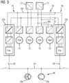
- FIG. 3 Another example of a power supply device 8b is shown in FIG. 3 shown schematically.
- the descriptions of subsequent embodiments are generally limited essentially to the differences from the previous embodiments of the previous figures, which are referred to with regard to features and functions that remain the same.
- Substantially identical components are basically numbered with the same reference numerals, and features not mentioned are adopted in the following exemplary embodiments without being described again.
- the two segments 16c, 16d of the intermediate circuit 16 are connected to each other via a switching means 28, can be switched by the multiple operating modes of the power supply device 8b.
- the switching means 28 in each case has a switch on both DC phases of both input converter 12, so that four essential switching states can be switched.
- the power supply unit 22c is also disconnected from both input power converters 12 and thus out of operation.
- the left input power converter 12 supplies not only the segment 16a of the intermediate circuit 16, but additionally the power supply unit 22c.
- the remaining part of the right segment 16 d of the intermediate circuit 16 is separated from the left input converter 12 and the segment 16 c and is supplied by the right input converter 12.
- the two power supply units 22b, 22c can be designed with different power, wherein the power of the power supply unit 22b alone sufficient to supply the AC train busbar 24 and all connected to her operating units of the brake system 26 in each regular operating situation.
- the switching means 28 In regular operation of the rail vehicle 2, therefore, the switching means 28 is open, so that all switches of the switching means 28 are open.
- the left input power converter 12 supplies the left intermediate circuit segment 16c
- the right input power converter 12 supplies only the two motor inverters 18 of the right side, and the right intermediate circuit 16d with the drive motors connected thereto 10.
- the right power supply unit 22c is out of operation.
- the AC train bus 24 is therefore powered only by the more powerful power supply unit 22b with operating power.
- the control unit 20 switches the switching means 28 such that the power supply of the AC train busbar 24 takes place exclusively via the less powerful power supply unit 22c. This can be done by closing all switches and interconnecting the two DC link segments 16c, 16d. It is also possible to close the upper switch and keep the lower switch open, so that the less powerful power supply unit 22 c is also supplied by the left input power converter 12. It is also possible to keep the upper switch open and close the lower, so that the power supply unit 22 c is powered by the right input power converter 12.
- the less powerful power supply unit 22c can optionally be powered by the remaining input power converter 12 by closing the upper switch and opening the lower one and the left input power converter 12 supplies the power supply unit 22c or the upper switch is open and bottom switch closed, so that the right input power converter 12 supplies the power supply unit 22c. This is particularly advantageous if one of the input power converter 12 and the more powerful power supply unit 22b fails.
- the AC train busbar 24 is reliably supplied with operating power, even if at least one input power converter 12 and a power supply unit 22b, 22c are intact. Will the AC train bus 24 supplied only by the less powerful power supply unit 22c, so there may not be enough energy for all connected to this bus operating units available. However, there is enough power to provide the necessary enough for an electrodynamic emergency braking operating units of the brake system 26 with energy.
- FIG. 4 Another embodiment of a power supply device 8c is shown in FIG FIG. 4 shown.
- one of the power supply units 22c is powered via a DC power source 30a in the form of a battery.
- This embodiment has the advantage that the AC train busbar 24 is also supplied with operating power for at least the necessary for the electrodynamic braking operating units of the brake system 26 when the entire DC link 16 is de-energized, for example, because no energy is retrievable from the railway network or both Input converter 12 are defective.
- the DC power source 30a is intermediate circuit-free, that is independent of a DC link 16 can be used.
- a DC train busbar may be used as the DC power source 30a. This would be operated in a failure of the intermediate circuit 16 with at least one DC storage in another car or attach to a busbar of another driven car.
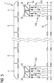
- FIG. 5 shows the rail vehicle 2 with two driven car 4 and a plurality of non-driven car 6.
- the rail vehicle 2 has a DC train bus bar 32 which passes through the entire rail vehicle 2, so all cars 4, 6 passes.
- the guided by the train and also in FIG. 1 shown DC train busbar 32 is supplied at the front end of the train and at the rear end of the train by two power supply units 34 a with DC power, the unillustrated operating units of the non-driven carriage 6 supplied with operating current.
- the power of the controlled inverters 36 is sized so that all the operating aggregates of the non-driven carriages 6 can be supplied with operating power when the DC train bus 32 is powered by at least two controlled inverters 36.
- the power of the controlled inverters 36 is sufficient to be able to supply the operating units of the non-driven carriages 6, which are required for emergency braking, only by a controlled converter 36.
- the DC train bus 32 is torn into two parts, but fed at each possible variation of simple train separation from a power supply unit 34a. In this way, the brakes of the non-driven car 6 always remain fully functional even with a simple train separation.
- each controlled inverter 36 on the input side gets no energy, for example, by a technical defect of the rail vehicle 2
- all power supply units 34a are equipped with at least two DC memories 30a, can be supplied by the at least the brake units of the non-driven carriage 6 with sufficient operating energy
- each controlled inverter 36 is connected to a DC storage 30a, so that each of the power supply units 34a has two segments each having a controlled inverter 36 and a DC storage 30a.
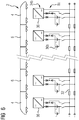
- each non-driven carriage 6 of the rail vehicle 2 is provided with a power supply unit 34b, the power of which should be such that it is connected in pairs, in particular even alone, all connected to the DC train bus 32 Supply operating units of their own car 4, 6.
- a power supply unit 34b the power of which should be such that it is connected in pairs, in particular even alone, all connected to the DC train bus 32 Supply operating units of their own car 4, 6.
- an excess power so that the DC train busbar 32 can be repeatedly redundantly supplied by several power supply units 34b with operating power.
- each power supply unit 34b By equipping each non-driven wagon 6 with a power supply unit 34b, this energy supply to the brake units is ensured in any case, even with a multiple train separation - regardless of the location or locations of the train separation.
- each power supply unit 34b In order to have operating energy for brake units available even in the event of a power failure or a DC link failure, each power supply unit 34b is equipped with two DC storage devices 30a, analogous to FIG. 5 which, either alone or together, provide sufficient power for the aggregates necessary for braking.
- the controlled inverter 36 of both embodiments of the Figures 5 and 6 may be connected on the input side to the AC train busbar 24 of the power supply device 8. It is also possible to feed the DC train bus 32 directly from the DC link 16 and to switch a corresponding power converter between the DC bus 16 and the DC train bus 32. This would then expediently a buck converter.
- the power supply devices 8a, 8b and 8c can be easily combined with the power supply device 8d or 8e, so that a power supply device 8 with power supply units 22 and power supply units 34 is present.
- FIG. 7 Another embodiment is in FIG. 7 shown schematically.
- the power supply device 8f has a connection to the operating units 58a-d of the brake system 26 AC line system 38, which may include one or more AC lines 38a, 38b.
- the line system 38 from FIG. 7 comprises two alternating current lines 38a, 38b connected in parallel, which each connect one of the two power supply units 22a to the operating units 58a-d of the brake system 26.
- a switching means 42 is present in each of the two AC lines 38a, 38b. From the AC train bus 24 passing through the entire train, an AC branch 60 branches off. This is coupled via a switching means 54 to the AC line system 38.
- the two power supply units 22a are each connected and disconnectably connected to the AC train bus 24 via a switching means 40. The connection of the AC line system 38 to the power supply units 22a remains unaffected due to the structural arrangement by the switching means 40.
- Each one of the operating units 58a-d of the brake system 26 has a single AC supply line 44a-d, which is connected via a switching means 56 to the AC line system 38.
- the operating units 58a-d of the brake system 26 are redundant, and therefore there are two coolant pumps 58a and 58b and two fans 58c and 58d.
- the control unit 20 disconnects the relevant power supply unit 22a from the operating units 58a-d of the brake system 26. This is done via the actuation of the switching means 42 in the AC power lines 38a and 38b. In this case, the AC line 38a or 38b coupled to the defective power supply unit 22a is disconnected from the operating units 58a-d.
- the AC line 38a or 38b of the intact power supply unit 22a is or remains connected by the switching means 42 with the operating units 58a-d. This ensures that the power supply of the brake system 26 in case of failure of one of both power supply units 22a is maintained. For this purpose, the rated power of in FIG.
- both power supply units 22a fail, it may be that power is available to the AC train busbar 24, which runs through the entire train, at least for emergency operation from another railcar.
- the switching means 54 is closed and the switching means 40 and 42 are opened. By operation of the switching means 40 and 42, the power supply units 22a are disconnected from the AC train bus bar 24 and the AC power line 38. Actuation of the switching means 54 establishes communication between the AC train bus 24 via the AC branch 60 with the AC line 38.
- An identically-acting, structurally-alternative arrangement may provide two additional switching means instead of the alternating-current branch line 60 and the switching means 54.
- These switching means can each be arranged between the relevant energy supply unit 22a and the connection of the alternating current lines 38a and 38b to a connecting line from the relevant energy supply unit 22a to the train busbar 24. If both power supply units 22a fail, the additional switching means are opened and the switching means 40 is closed so that the powering of the operating units 58a-d of the braking system 26 from the AC train bus 24 can be via one or both AC lines 38a and / or 38b.
- a defective operating aggregate 58a-d is disconnected from the AC line 38 by the switching means 56. This will prevent the rated potential of the AC train busbar 24 or the AC line 38 is drawn to a significantly lower and insufficient to supply the brake system 26 potential.
- FIG. 8 shows a further embodiment of a power supply device 8g.
- the power supply device 8g has a further energy supply unit 22d.
- the energy supply unit 22d is present in addition to the two energy supply units 22a and connected via a further AC line 46 to the operating units 58a-d of the brake system 26.
- a switching means 48 for connecting and disconnecting the coupling between the power supply unit 22 d and the operating units 58 a - d of the brake system 26 is arranged on the AC line 46.
- Two DC link segments 16g and 16h are arranged between the input power converters 12 and the power supply units 22a.
- the two input phases of the inverter of the power supply unit 22d are connected via a switching means 28 to the DC phases of the input power converters 12, whereby a plurality of operation modes of the power supply device 8g can be switched.
- the switching means 28 has in each case one switch on each of the two DC phases of the two input current converters 12, so that four essential switching states can be switched: If all switches of the switching means 28 are closed, then the power supply unit 22d is supplied jointly by both input power converters 12.
- the left input converter 12 feeds the power supply unit 22d in addition to the segment 16g of the intermediate circuit 16.
- the right-hand input converter 12 feeds the energy supply unit 22d in addition to the segment 16h of the intermediate circuit 16.
- control unit 20 switches the switches of the switching means 28 in such a way that the inputs of the power supply unit 22 d are connected to the positive and negative pole of the intact input converter 12 and separated from those of the defective input converter 12 ,
- both input power converters 12 fail due to defects or systematic software errors, all the power supply units 22a and 22d are inoperative and the control unit 20 opens the switching means 40, 42, 48 and closes the switching means 54.
- the operating units 58a-d of the alternating current -Zugsammelschiene 24 are supplied with operating power.
- the AC train busbar 24 runs through the entire train and is therefore also provided in case of failure of the power supply units 22a and 22d and / or the input power converter 12 to maintain the power supply of the operating units 58a-d of the brake system 26.
- a failure of the AC train busbar 24 may occur in particular in the unwanted case of a single or double train separation.
- the necessary for an electrodynamic emergency braking safe power supply of the operating units 58a-d of the brake system 26 is ensured even with simultaneous failure of the power supply devices 22a and the AC train busbar 24. This applies if at least one input converter 12 and the power supply unit 22d are in a functional state.
- the rated power of in FIG. 8 shown power supply units 22a with each a / 2 kVA identical and dimensioned so that the operating units 58a-d of the brake system 26 can be sufficiently supplied by operating power only from a single power supply unit 22a even in normal operation.
- the rated power of the power supply unit 22d can be designed by the structurally given redundancy of the power supply solely to the energy requirements of the operating units 58a-d of the brake system 26 in emergency mode and thus much lower, eg to a / 10 kVA, are measured.
- FIG. 9 Another embodiment of a power supply device 8h is shown in FIG. 9 shown schematically.
- the arrangement of the power supply units 22a, the AC train busbar 24, the AC lines 38 and the AC branch line 60 is in its effect on the supply of the brake system 26 analogous to that in FIG. 7 designed variant illustrated. The same applies to the switching means 40, 42 and 54.
- a DC power source 30a is arranged to feed another power supply unit 22c.
- the power supply unit 22c is connectable and separable to the operating units 58a-d of the brake system 26 via an alternating current line 46 and a switching means 48.
- the DC power source 30a is intermediate circuit-free, so at least temporarily independent of the fed from the input converters 12 segments 16a and 16b of the intermediate circuit 16 can be used.
- the DC power source 30a may be embodied, for example, as a battery.
- the DC power source 30a e.g. For the purpose of their electrical charge or recharge, be connected to the DC train bus 32.
- This in FIG. 9 illustrated embodiment has the advantage that the secure power supply of the operating units 58a-d is guaranteed even in the case of a defect of both input converter 12 and simultaneous failure of the AC train busbar 24.
- the control unit 20 switches in such an accident, the switching means so that the switching means 48 is closed, the switching means 40, 42 and 52 are opened.
- the braking system is then supplied with operating energy solely by the power supply unit 22c.
- the rated power of the power supply unit 22c can be chosen so that it is sufficient to supply the brake system 26 in case of failure and be limited eg to a / 10 kVA.
- the rated power of the power supply units 22a may be designed, for example, at a / 2 kVA, so that a secure supply of the alternating current train busbar 24 is ensured.
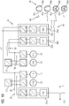
- FIG. 10 shows a further embodiment of a power supply device 8i with three redundant power supply units 22a and 22d.
- the power supply unit 22a is connected to an input converter 12, which also supplies an intermediate circuit 16i, and is designed to supply the AC busbar 24.
- a switching means 40 is arranged to disconnect and connect the power supply unit 22 a from the AC train bus bar 24.
- Another input converter 12 is connected to a DC link 16j.
- the two further power supply units 22d are coupled to the operating units 58a-58d of the brake system 26 for supplying them with operating power via AC lines 46a and 46b.
- each of the power supply units 22d is connected to a single one of the AC power lines 46a and 46b.
- each of the AC power lines 46a and 46b is connected to only one of the power supply units 22d.
- a switching means 48 for connecting and disconnecting the coupling between the power supply units 22d and the operating units 58a-d of the brake system 26 is disposed on each of the AC lines 46a and 46b.
- the two power supply units 22d are connected via a switching means 50 separable and connectable to the two input power converter 12.
- the structural arrangement is made so that in each case one of the power supply units 22d is fed by a single one of the input power converter 12. Also, each of the input power converters 12 feeds only a single one of the power supply units 22d.
- This type of connection between the input converters 12 and the power supply units 22d results in three essential switching states of the switching means 50: If the two upper switches of the switching means 50 are closed and the lower switches are opened, then the left input converter 12 feeds the energy supply unit 22d in addition to the segment 16i of the intermediate circuit 16.
- the right-hand input converter 12 feeds the energy supply unit 22d in addition to the segment 16j of the intermediate circuit 16.
- the control unit 20 switches the switches of the switching means 50 such that the inputs of the power supply units 22d are connected to the plus and minus terminals of the intact input converter 12 and disconnected from those of the defective input converter 12 .
- the nominal powers of the two power supply units 22d are each dimensioned for a sufficient supply of the operating units 58a-d of the brake system 26 in normal operation and e.g. each with a / 4 kVA provided.
- the rated power of the power supply unit 22a may be e.g. be executed on a kVA, so that a secure supply of the AC train busbar 24 is ensured.
- each of the power supply units 22d may be connected to each of the input power converters 12.
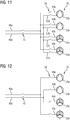
- FIG. 11 A representation of an alternative, redundant power supply of the operating units 58a-d, which is also applicable to the power supply devices 8 of FIGS. 7 to 10, is shown in FIG. 11 shown.
- Each one of the operating units 58a-d is connected to the AC power lines 46a and 46b via two AC power supply lines 44 and 52, respectively.
- Each of the AC supply lines 44 is connected to one and only one of the AC lines 46a or 46b.
- each of the AC power supply lines 52 is connected to one and only one of the AC power lines 46a or 46b.
- the AC power leads 44 and 52 are connected to another AC power line 46a or 46b, respectively.
- the invention can also be developed by providing more than the two AC supply lines 44 and 52 per operating unit 58 and more than the two AC lines 46a and 46b for connection.
- FIG. 12 shows a further embodiment of the power supply device 8.
- the operating units 58a-d of the brake system 26 in two aggregate groups, ie subsets of the totality of all operating units 58, divided.
- Each of the two subsets of elements 58a and 58d and 58b and 58c are connected to one and only one of the AC lines 46a or 46b.
- each of the AC power lines 46a and 46b is connected to only one of the aggregate groups. Due to this type of connection, despite the restriction to a single AC supply line 44a-d per operating unit 58a-d, increased availability of the energy supply is produced. If one of the AC line 46a or 46b fails due to a defect, the power supply of the operating units 58a-d of the brake system 26 can be maintained by the other.
Landscapes
- Engineering & Computer Science (AREA)
- Mechanical Engineering (AREA)
- Transportation (AREA)
- Power Engineering (AREA)
- Life Sciences & Earth Sciences (AREA)
- Sustainable Development (AREA)
- Sustainable Energy (AREA)
- Physics & Mathematics (AREA)
- Electromagnetism (AREA)
- Electric Propulsion And Braking For Vehicles (AREA)
Claims (13)
- Dispositif (8, 8a-i) d'alimentation en courant d'un véhicule (2) ferroviaire, qui comprend au moins une voiture (4) entraînée, comprenant- un circuit (16) intermédiaire,- un système (26) de frein,- un système d'alimentation en énergie, le système d'alimentation en énergie comportant au moins deux unités (22a-c) montées sur le circuit (16) intermédiaire d'alimentation en énergie de la voiture (4) entraînée, afin d'alimenter, de manière redondante en énergie, le système (26) de frein,- deux convertisseurs (12) de courant d'entrée pour la voiture (4) entraînée pour l'alimentation respective de tout le circuit (16) intermédiaire en énergie et- un moyen (28) de commutation pour connecter les deux convertisseurs (12) de courant d'entrée à au moins l'une des unités (22b, 22c) d'alimentation en énergie pour son alimentation en énergie, le moyen (28) de commutation étant prévu pour séparer le circuit (16) intermédiaire en deux segments (16c, 16d) qui sont séparés l'un de l'autre, qui sont alimentés par respectivement un convertisseur (12) de courant d'entrée et qui ont chacun une unité (22b, 22c) d'alimentation en énergie,caractérisé en ce que
le moyen (28) de commutation est prévu, en outre, pour connecter les deux unités (22b, 22c) d'alimentation en énergie à l'un des deux convertisseurs (12) de courant d'entrée, alors que les segments (16c, 16d) sont sinon séparés, ainsi que pour séparer l'une des unités (22c) d'alimentation en énergie des deux convertisseurs (12) de courant d'entrée. - Dispositif (8, 8a-e) d'alimentation en courant suivant la revendication 1,
caractérisé par une ligne (24) de train à courant alternatif, pour alimenter le système de frein en énergie de fonctionnement, les deux unités (22a-c) d'alimentation en énergie étant réalisées pour l'alimentation redondante en énergie de la ligne (24) de train à courant alternatif. - Dispositif (8, 8b) d'alimentation en courant suivant la revendication 1 ou 2,
caractérisé en ce que les deux unités (22a-c) d'alimentation en énergie sont associées chacune à un propre segment (16a-f) du circuit (16) intermédiaire et les deux segments (16a-f) sont séparés l'un de l'autre et servent, par l'intermédiaire des unités (22a-c) d'alimentation en énergie, à l'alimentation redondante en énergie de la ligne (24) de train à courant alternatif. - Dispositif (8, 8b-e) d'alimentation en courant suivant la revendication 1,
caractérisé en ce que l'unité (22c) d'alimentation en énergie, ayant la puissance la plus petite, est connectée à au moins deux convertisseurs (2) de courant d'entrée et l'unité (22b) d'alimentation en énergie la plus puissante est conçue ou préparée pour, en fonctionnement régulier, alimenter seule en énergie la ligne de train à courant alternatif. - Dispositif (8, 8a-e) d'alimentation en courant suivant l'une des revendications précédentes,
caractérisé par un accumulateur (30a) de courant continu, qui est connecté à au moins l'une des unités (22c) d'alimentation en énergie et qui est conçu pour alimenter en énergie la ligne (24) de train à courant alternatif par l'intermédiaire de l'unité (22c) d'alimentation en énergie. - Dispositif (8, 8a-e) d'alimentation en courant suivant l'une des revendications précédentes,
caractérisé par une ligne (32) de train à courant continu, le système d'alimentation en énergie comportant au moins deux unités (34) d'alimentation en énergie pour l'alimentation redondante en énergie de la ligne (32) de train à courant continu. - Dispositif (8, 8a-e) d'alimentation en courant suivant la revendication 6,
caractérisé par une source de courant continu supplémentaire aux unités (34) d'alimentation en énergie, qui est prévue pour alimenter la ligne (32) de courant à courant continu. - Dispositif (8, 8a-e) d'alimentation en courant suivant la revendication 6 ou 7,
caractérisé en ce que les unités (34) d'alimentation en énergie alimentant la ligne (32) de train à courant continu ont chacune au moins deux accumulateurs (30b) de courant continu. - Dispositif (8, 8a-i) d'alimentation en courant suivant l'une des revendications précédentes,
caractérisé par une ligne (24) de train à courant alternatif, à laquelle sont connectées par montage parallèle les deux unités (22a) d'alimentation en énergie, et un certain nombre de lignes (38, 38a-b) à courant alternatif connectées au système (26) de frein pour l'alimentation du système (26) de frein en énergie de freinage, lignes auxquelles les deux unités (22a) d'alimentation en énergie sont connectées par un montage en parallèle, et un moyen (54) de commutation pour connecter le certain nombre de lignes (38, 38a-b) à courant alternatif à la ligne (24) de train à courant alternatif et pour les en séparer. - Dispositif (8, 8a-i) d'alimentation en courant suivant la revendication 9,
caractérisé en ce que les deux unités (22a) d'alimentation en énergie sont connectées chacune à leur propre convertisseur de courant d'entrée et il y a une autre unité (22d) d'alimentation en énergie, qui est connectée à l'un des convertisseurs (12) de courant d'entrée de l'une des autres unités (22a, 22b) d'alimentation en énergie et, par l'intermédiaire d'une autre ligne (46) à courant alternatif, est connectée, sans couplage de la ligne (24) de rail à courant alternatif, par un moyen (48) de commutation, au système de frein et est conçue pour son alimentation redondante en énergie. - Dispositif (8, 8a-i) d'alimentation en courant suivant la revendication 9 ou 10,
caractérisé en ce qu'une autre unité (22c) d'alimentation en énergie est alimentée à partir d'un accumulateur (30a) de courant continu sans circuit intermédiaire et est connectée par une autre ligne (46) à courant alternatif, sans couplage de la ligne (24) de train à courant alternatif, par un moyen (48) de commutation, au système de frein et est conçue pour son alimentation redondante en énergie. - Dispositif (8, 8f-i) d'alimentation en courant suivant l'une des revendications précédentes,
caractérisé par plusieurs lignes (38, 38a-b) à courant alternatif connectées au système (26) de frein pour l'alimentation du système (26) de frein en énergie de fonctionnement, lignes auxquelles les deux unités (22a) d'alimentation en énergie sont connectées par un montage en parallèle, le système (26) de frein ayant plusieurs groupes (58a-d) de fonctionnement, qui disposent chacun de plusieurs lignes (44, 52) d'arrivée de courant alternatif, qui procurent une connexion des groupes (58a-d) de fonctionnement aux lignes (38a-b, 46a-b) à courant alternatif, le nombre des lignes d'arrivée de courant alternatif correspondant au nombre des lignes à courant alternatif. - Dispositif (8, 8f-i) d'alimentation en courant suivant l'une des revendications précédentes,
caractérisé par plusieurs lignes (38, 38a-b) à courant alternatif connectées au système (26) de frein pour l'alimentation du système (26) de frein en énergie de fonctionnement, le système (26) de frein ayant plusieurs groupes (58a-d) de fonctionnement, qui sont présents chacun de manière redondante et qui sont subdivisés en sous-ensembles, et chaque sous-ensemble et chaque groupe de fonctionnement est alimenté respectivement à partir de, respectivement, seulement l'une des lignes de courant alternatif.
Applications Claiming Priority (2)
| Application Number | Priority Date | Filing Date | Title |
|---|---|---|---|
| DE102012223901.4A DE102012223901B4 (de) | 2012-12-20 | 2012-12-20 | Stromversorgungseinrichtung für ein Schienenfahrzeug |
| PCT/EP2013/077033 WO2014095961A1 (fr) | 2012-12-20 | 2013-12-18 | Système d'alimentation électrique d'un véhicule ferroviaire |
Publications (2)
| Publication Number | Publication Date |
|---|---|
| EP2909068A1 EP2909068A1 (fr) | 2015-08-26 |
| EP2909068B1 true EP2909068B1 (fr) | 2019-06-12 |
Family
ID=49885237
Family Applications (1)
| Application Number | Title | Priority Date | Filing Date |
|---|---|---|---|
| EP13814509.9A Active EP2909068B1 (fr) | 2012-12-20 | 2013-12-18 | Système d'alimentation électrique d'un véhicule ferroviaire |
Country Status (7)
| Country | Link |
|---|---|
| US (1) | US9889866B2 (fr) |
| EP (1) | EP2909068B1 (fr) |
| CN (1) | CN104884320B (fr) |
| DE (1) | DE102012223901B4 (fr) |
| ES (1) | ES2745261T3 (fr) |
| TR (1) | TR201910004T4 (fr) |
| WO (1) | WO2014095961A1 (fr) |
Families Citing this family (17)
| Publication number | Priority date | Publication date | Assignee | Title |
|---|---|---|---|---|
| CN104608775A (zh) * | 2014-12-10 | 2015-05-13 | 南车四方车辆有限公司 | 混合式动力分散型动车组 |
| CN104527444B (zh) * | 2014-12-16 | 2017-01-11 | 株洲南车时代电气股份有限公司 | 一种用于地铁车辆的供电系统及方法 |
| US10112890B2 (en) * | 2015-01-19 | 2018-10-30 | Showa Denko K.K. | Compound, salt of compound, external agent for skin, cosmetic, and food additive |
| CN106274492B (zh) * | 2015-05-27 | 2018-10-26 | 中车大连电力牵引研发中心有限公司 | 轨道车辆用辅助变流装置及轨道车辆 |
| JP6510060B2 (ja) * | 2015-10-01 | 2019-05-08 | 株式会社東芝 | 鉄道車両用電力変換装置 |
| DE102016209553A1 (de) * | 2016-06-01 | 2017-12-07 | Bombardier Transportation Gmbh | Elektrisches System eines Schienenfahrzeugs, Schienenfahrzeug und Verfahren zum Betrieb eines elektrischen Systems |
| US10730391B2 (en) | 2017-02-16 | 2020-08-04 | Ford Global Technologies, Llc | Control of redundant power architecture for a vehicle |
| US10407003B2 (en) * | 2017-02-16 | 2019-09-10 | Ford Global Technologies, Llc | Short-circuit protection for vehicle redundant power architecture |
| DE102017106119A1 (de) * | 2017-03-22 | 2018-09-27 | Knorr-Bremse Systeme für Schienenfahrzeuge GmbH | Bremsvorrichtung für Schienenfahrzeuge und Verfahren zum Bremsen von Schienenfahrzeugen |
| DE102017208887A1 (de) * | 2017-05-24 | 2018-11-29 | Knorr-Bremse Systeme für Schienenfahrzeuge GmbH | Elektropneumatische Bremseinrichtung mit sicherer Stromversorgung zur Realisierung einer Notbremsfunktion |
| DE102017210750A1 (de) * | 2017-06-27 | 2018-12-27 | Siemens Aktiengesellschaft | Bordnetz für ein Schienenfahrzeug, Verfahren zum Betreiben des Bordnetzes und Schienenfahrzeug |
| DE102017213306A1 (de) * | 2017-08-01 | 2019-02-07 | Siemens Aktiengesellschaft | Energieversorgungseinrichtung für ein Schienenfahrzeug |
| DE102019212521A1 (de) * | 2019-08-21 | 2021-02-25 | Siemens Mobility GmbH | Schienenfahrzeug mit Sicherheitsschleifen |
| CN111806235B (zh) * | 2020-07-22 | 2022-06-07 | 西南交通大学 | 一种车地一体多功能应急储能供电系统及其控制方法 |
| US11999267B2 (en) | 2021-01-20 | 2024-06-04 | Abb Schweiz Ag | Power line system with ripple generator for electric vehicles |
| FR3120447B1 (fr) * | 2021-03-03 | 2024-10-11 | Alstom Transp Tech | Véhicule comprenant un témoin de présence tension sur un connecteur et ensemble associé |
| DE102021207374A1 (de) * | 2021-07-12 | 2023-01-12 | Knorr-Bremse Systeme für Nutzfahrzeuge GmbH | Energieversorgungsmanagementsystem für ein Fahrzeug, Verfahren für einen Betrieb des Energiemanagementsystems und Computerprogrammprodukt zur Durchführung des Verfahrens |
Citations (3)
| Publication number | Priority date | Publication date | Assignee | Title |
|---|---|---|---|---|
| US4795859A (en) * | 1987-01-14 | 1989-01-03 | Kabushiki Kaisha Toshiba | Control device for electric train |
| DE102008031001A1 (de) * | 2008-06-30 | 2009-12-31 | Siemens Aktiengesellschaft | Schienenfahrzeug und Verfahren zur Energieversorgung eines Schienenfahrzeugs |
| DE102009008549A1 (de) * | 2009-02-12 | 2010-08-19 | Bombardier Transportation Gmbh | Anordnung zum Betreiben von Verbrauchern in einem Schienenfahrzeug mit elektrischer Energie, wahlweise aus einem Energieversorgungsnetz oder aus einer Motor-Generator-Kombination |
Family Cites Families (7)
| Publication number | Priority date | Publication date | Assignee | Title |
|---|---|---|---|---|
| US7472011B2 (en) * | 2005-01-12 | 2008-12-30 | Wabtec Holding Corporation | Brake interface module |
| DE102005007336A1 (de) * | 2005-02-17 | 2006-08-31 | Siemens Ag | Bremsvorrichtung für ein Schienenfahrzeug |
| DE102006051317A1 (de) * | 2006-10-31 | 2008-05-08 | Knorr-Bremse Systeme für Schienenfahrzeuge GmbH | Verfahren zum generatorischen Bremsen eines Schienenfahrzeugs mit unterlegtem passiven Ersatzbremskreis und Vorrichtung zur Ausführung des Verfahrens |
| DE102008023332B4 (de) * | 2008-05-13 | 2010-12-02 | Siemens Aktiengesellschaft | Dieselelektrisches Antriebssystem |
| DE102009042965A1 (de) * | 2009-09-23 | 2011-03-24 | Siemens Aktiengesellschaft | Bremssystem mit intelligentem Aktuator zum Abbremsen eines schienengeführten Fahrzeugs |
| DE102010025036A1 (de) * | 2010-06-24 | 2011-12-29 | Siemens Aktiengesellschaft | Schienenfahrzeug |
| CN201834010U (zh) * | 2010-09-02 | 2011-05-18 | 北京二七轨道交通装备有限责任公司 | 列车及其安全制动系统 |
-
2012
- 2012-12-20 DE DE102012223901.4A patent/DE102012223901B4/de active Active
-
2013
- 2013-12-18 CN CN201380067616.4A patent/CN104884320B/zh active Active
- 2013-12-18 US US14/654,158 patent/US9889866B2/en not_active Expired - Fee Related
- 2013-12-18 WO PCT/EP2013/077033 patent/WO2014095961A1/fr not_active Ceased
- 2013-12-18 TR TR2019/10004T patent/TR201910004T4/tr unknown
- 2013-12-18 ES ES13814509T patent/ES2745261T3/es active Active
- 2013-12-18 EP EP13814509.9A patent/EP2909068B1/fr active Active
Patent Citations (3)
| Publication number | Priority date | Publication date | Assignee | Title |
|---|---|---|---|---|
| US4795859A (en) * | 1987-01-14 | 1989-01-03 | Kabushiki Kaisha Toshiba | Control device for electric train |
| DE102008031001A1 (de) * | 2008-06-30 | 2009-12-31 | Siemens Aktiengesellschaft | Schienenfahrzeug und Verfahren zur Energieversorgung eines Schienenfahrzeugs |
| DE102009008549A1 (de) * | 2009-02-12 | 2010-08-19 | Bombardier Transportation Gmbh | Anordnung zum Betreiben von Verbrauchern in einem Schienenfahrzeug mit elektrischer Energie, wahlweise aus einem Energieversorgungsnetz oder aus einer Motor-Generator-Kombination |
Also Published As
| Publication number | Publication date |
|---|---|
| CN104884320A (zh) | 2015-09-02 |
| ES2745261T3 (es) | 2020-02-28 |
| CN104884320B (zh) | 2017-06-13 |
| US20150353109A1 (en) | 2015-12-10 |
| US9889866B2 (en) | 2018-02-13 |
| TR201910004T4 (tr) | 2019-08-21 |
| DE102012223901B4 (de) | 2024-09-26 |
| EP2909068A1 (fr) | 2015-08-26 |
| WO2014095961A1 (fr) | 2014-06-26 |
| DE102012223901A1 (de) | 2014-06-26 |
Similar Documents
| Publication | Publication Date | Title |
|---|---|---|
| DE102012223901B4 (de) | Stromversorgungseinrichtung für ein Schienenfahrzeug | |
| DE102011082516B4 (de) | Schienenfahrzeugsverband | |
| EP2800672B1 (fr) | Dispositif de freinage de véhicule sur rails | |
| EP3634803B1 (fr) | Source de puissance pour un vehicule ferroviare | |
| EP3300982A1 (fr) | Système d'alimentation en énergie d'un véhicule sur rail | |
| EP3584107A1 (fr) | Interconnexion des véhicules et procédé d'alimentation d'un réseau embarqué électrique dans une telle interconnexion | |
| AT500328A1 (de) | Fahrzeug mit batteriefahrt und verfahren zum betrieb eines solchen fahrzeuges | |
| EP3615370A1 (fr) | Réseau de bord pour un véhicule ferroviaire, procédé pour le fonctionnement du réseau de bord et véhicule ferroviaire | |
| EP3283322B1 (fr) | Dispositif protecteur d'entraînement servant à protéger un système d'entraînement | |
| DE102006042945B4 (de) | Verfahren zur Effizienzsteigerung von dieselelektrisch getriebenen Fahrzeugen und Fahrzeug zur Durchführung des Verfahrens | |
| EP3634823B1 (fr) | Dispositif comprenant un moyen de commande d'entraînement, véhicule comprenant un tel dispositif et procédé de fonctionnement d'un moyen de commande d'entraînement | |
| EP3630571B1 (fr) | Système de transport à traction par câble et procédé pour faire fonctionner ce système | |
| EP2399800A2 (fr) | Véhicule sur rail | |
| AT521412B1 (de) | Schienenfahrzeug | |
| EP4063169B1 (fr) | Système de traction du véhicule | |
| DE102022104099B3 (de) | Verfahren zum Betrieb eines Hybrid-Batterieoberleitungsfahrzeugs und Hybrid-Batterieoberleitungsfahrzeug | |
| EP3184350A1 (fr) | Véhicule sur rail et système de transport | |
| EP3150420A1 (fr) | Groupes d'entrainement pour vehicules | |
| EP4328074A1 (fr) | Véhicule ferroviaire, procédé permettant de faire fonctionner le véhicule ferroviaire, ainsi qu'utilisation d'une batterie de traction | |
| EP3798042B1 (fr) | Véhicule ferroviaire alimenté par batteries | |
| EP3929019B1 (fr) | Vehicule, en particulier vehicule ferroviaire avec traction- et réseau de bord | |
| DE102011104223A1 (de) | Verfahren zur Deaktivierung eines Hochspannungsnetzes mit einer zugeordneten Hochspannungsbatterie eines Kraftfahrzeugs und Kraftfahrzeug | |
| DE102013204603A1 (de) | Verfahren zum Betreiben eines Schienenfahrzeugs | |
| DE102019133632A1 (de) | Redundantes Energieversorgungssystem für elektrisch betriebenes Fahrzeug |
Legal Events
| Date | Code | Title | Description |
|---|---|---|---|
| PUAI | Public reference made under article 153(3) epc to a published international application that has entered the european phase |
Free format text: ORIGINAL CODE: 0009012 |
|
| 17P | Request for examination filed |
Effective date: 20150521 |
|
| AK | Designated contracting states |
Kind code of ref document: A1 Designated state(s): AL AT BE BG CH CY CZ DE DK EE ES FI FR GB GR HR HU IE IS IT LI LT LU LV MC MK MT NL NO PL PT RO RS SE SI SK SM TR |
|
| AX | Request for extension of the european patent |
Extension state: BA ME |
|
| DAX | Request for extension of the european patent (deleted) | ||
| RAP1 | Party data changed (applicant data changed or rights of an application transferred) |
Owner name: SIEMENS AKTIENGESELLSCHAFT |
|
| STAA | Information on the status of an ep patent application or granted ep patent |
Free format text: STATUS: EXAMINATION IS IN PROGRESS |
|
| 17Q | First examination report despatched |
Effective date: 20180403 |
|
| RAP1 | Party data changed (applicant data changed or rights of an application transferred) |
Owner name: SIEMENS MOBILITY GMBH |
|
| GRAP | Despatch of communication of intention to grant a patent |
Free format text: ORIGINAL CODE: EPIDOSNIGR1 |
|
| STAA | Information on the status of an ep patent application or granted ep patent |
Free format text: STATUS: GRANT OF PATENT IS INTENDED |
|
| INTG | Intention to grant announced |
Effective date: 20181214 |
|
| GRAJ | Information related to disapproval of communication of intention to grant by the applicant or resumption of examination proceedings by the epo deleted |
Free format text: ORIGINAL CODE: EPIDOSDIGR1 |
|
| STAA | Information on the status of an ep patent application or granted ep patent |
Free format text: STATUS: EXAMINATION IS IN PROGRESS |
|
| GRAP | Despatch of communication of intention to grant a patent |
Free format text: ORIGINAL CODE: EPIDOSNIGR1 |
|
| STAA | Information on the status of an ep patent application or granted ep patent |
Free format text: STATUS: GRANT OF PATENT IS INTENDED |
|
| INTG | Intention to grant announced |
Effective date: 20190125 |
|
| GRAS | Grant fee paid |
Free format text: ORIGINAL CODE: EPIDOSNIGR3 |
|
| GRAA | (expected) grant |
Free format text: ORIGINAL CODE: 0009210 |
|
| STAA | Information on the status of an ep patent application or granted ep patent |
Free format text: STATUS: THE PATENT HAS BEEN GRANTED |
|
| AK | Designated contracting states |
Kind code of ref document: B1 Designated state(s): AL AT BE BG CH CY CZ DE DK EE ES FI FR GB GR HR HU IE IS IT LI LT LU LV MC MK MT NL NO PL PT RO RS SE SI SK SM TR |
|
| REG | Reference to a national code |
Ref country code: GB Ref legal event code: FG4D Free format text: NOT ENGLISH |
|
| REG | Reference to a national code |
Ref country code: CH Ref legal event code: EP |
|
| REG | Reference to a national code |
Ref country code: AT Ref legal event code: REF Ref document number: 1142160 Country of ref document: AT Kind code of ref document: T Effective date: 20190615 |
|
| REG | Reference to a national code |
Ref country code: DE Ref legal event code: R096 Ref document number: 502013013004 Country of ref document: DE |
|
| REG | Reference to a national code |
Ref country code: CH Ref legal event code: NV Representative=s name: SIEMENS SCHWEIZ AG, CH |
|
| REG | Reference to a national code |
Ref country code: IE Ref legal event code: FG4D Free format text: LANGUAGE OF EP DOCUMENT: GERMAN |
|
| REG | Reference to a national code |
Ref country code: NL Ref legal event code: MP Effective date: 20190612 |
|
| REG | Reference to a national code |
Ref country code: LT Ref legal event code: MG4D |
|
| PG25 | Lapsed in a contracting state [announced via postgrant information from national office to epo] |
Ref country code: SE Free format text: LAPSE BECAUSE OF FAILURE TO SUBMIT A TRANSLATION OF THE DESCRIPTION OR TO PAY THE FEE WITHIN THE PRESCRIBED TIME-LIMIT Effective date: 20190612 Ref country code: NO Free format text: LAPSE BECAUSE OF FAILURE TO SUBMIT A TRANSLATION OF THE DESCRIPTION OR TO PAY THE FEE WITHIN THE PRESCRIBED TIME-LIMIT Effective date: 20190912 Ref country code: AL Free format text: LAPSE BECAUSE OF FAILURE TO SUBMIT A TRANSLATION OF THE DESCRIPTION OR TO PAY THE FEE WITHIN THE PRESCRIBED TIME-LIMIT Effective date: 20190612 Ref country code: LT Free format text: LAPSE BECAUSE OF FAILURE TO SUBMIT A TRANSLATION OF THE DESCRIPTION OR TO PAY THE FEE WITHIN THE PRESCRIBED TIME-LIMIT Effective date: 20190612 Ref country code: FI Free format text: LAPSE BECAUSE OF FAILURE TO SUBMIT A TRANSLATION OF THE DESCRIPTION OR TO PAY THE FEE WITHIN THE PRESCRIBED TIME-LIMIT Effective date: 20190612 Ref country code: HR Free format text: LAPSE BECAUSE OF FAILURE TO SUBMIT A TRANSLATION OF THE DESCRIPTION OR TO PAY THE FEE WITHIN THE PRESCRIBED TIME-LIMIT Effective date: 20190612 |
|
| PG25 | Lapsed in a contracting state [announced via postgrant information from national office to epo] |
Ref country code: RS Free format text: LAPSE BECAUSE OF FAILURE TO SUBMIT A TRANSLATION OF THE DESCRIPTION OR TO PAY THE FEE WITHIN THE PRESCRIBED TIME-LIMIT Effective date: 20190612 Ref country code: LV Free format text: LAPSE BECAUSE OF FAILURE TO SUBMIT A TRANSLATION OF THE DESCRIPTION OR TO PAY THE FEE WITHIN THE PRESCRIBED TIME-LIMIT Effective date: 20190612 Ref country code: BG Free format text: LAPSE BECAUSE OF FAILURE TO SUBMIT A TRANSLATION OF THE DESCRIPTION OR TO PAY THE FEE WITHIN THE PRESCRIBED TIME-LIMIT Effective date: 20190912 Ref country code: GR Free format text: LAPSE BECAUSE OF FAILURE TO SUBMIT A TRANSLATION OF THE DESCRIPTION OR TO PAY THE FEE WITHIN THE PRESCRIBED TIME-LIMIT Effective date: 20190913 |
|
| PG25 | Lapsed in a contracting state [announced via postgrant information from national office to epo] |
Ref country code: PT Free format text: LAPSE BECAUSE OF FAILURE TO SUBMIT A TRANSLATION OF THE DESCRIPTION OR TO PAY THE FEE WITHIN THE PRESCRIBED TIME-LIMIT Effective date: 20191014 Ref country code: EE Free format text: LAPSE BECAUSE OF FAILURE TO SUBMIT A TRANSLATION OF THE DESCRIPTION OR TO PAY THE FEE WITHIN THE PRESCRIBED TIME-LIMIT Effective date: 20190612 Ref country code: SK Free format text: LAPSE BECAUSE OF FAILURE TO SUBMIT A TRANSLATION OF THE DESCRIPTION OR TO PAY THE FEE WITHIN THE PRESCRIBED TIME-LIMIT Effective date: 20190612 Ref country code: CZ Free format text: LAPSE BECAUSE OF FAILURE TO SUBMIT A TRANSLATION OF THE DESCRIPTION OR TO PAY THE FEE WITHIN THE PRESCRIBED TIME-LIMIT Effective date: 20190612 Ref country code: RO Free format text: LAPSE BECAUSE OF FAILURE TO SUBMIT A TRANSLATION OF THE DESCRIPTION OR TO PAY THE FEE WITHIN THE PRESCRIBED TIME-LIMIT Effective date: 20190612 Ref country code: NL Free format text: LAPSE BECAUSE OF FAILURE TO SUBMIT A TRANSLATION OF THE DESCRIPTION OR TO PAY THE FEE WITHIN THE PRESCRIBED TIME-LIMIT Effective date: 20190612 |
|
| PG25 | Lapsed in a contracting state [announced via postgrant information from national office to epo] |
Ref country code: SM Free format text: LAPSE BECAUSE OF FAILURE TO SUBMIT A TRANSLATION OF THE DESCRIPTION OR TO PAY THE FEE WITHIN THE PRESCRIBED TIME-LIMIT Effective date: 20190612 Ref country code: IS Free format text: LAPSE BECAUSE OF FAILURE TO SUBMIT A TRANSLATION OF THE DESCRIPTION OR TO PAY THE FEE WITHIN THE PRESCRIBED TIME-LIMIT Effective date: 20191012 |
|
| REG | Reference to a national code |
Ref country code: ES Ref legal event code: FG2A Ref document number: 2745261 Country of ref document: ES Kind code of ref document: T3 Effective date: 20200228 |
|
| REG | Reference to a national code |
Ref country code: DE Ref legal event code: R097 Ref document number: 502013013004 Country of ref document: DE |
|
| PLBE | No opposition filed within time limit |
Free format text: ORIGINAL CODE: 0009261 |
|
| STAA | Information on the status of an ep patent application or granted ep patent |
Free format text: STATUS: NO OPPOSITION FILED WITHIN TIME LIMIT |
|
| PG25 | Lapsed in a contracting state [announced via postgrant information from national office to epo] |
Ref country code: PL Free format text: LAPSE BECAUSE OF FAILURE TO SUBMIT A TRANSLATION OF THE DESCRIPTION OR TO PAY THE FEE WITHIN THE PRESCRIBED TIME-LIMIT Effective date: 20190612 Ref country code: DK Free format text: LAPSE BECAUSE OF FAILURE TO SUBMIT A TRANSLATION OF THE DESCRIPTION OR TO PAY THE FEE WITHIN THE PRESCRIBED TIME-LIMIT Effective date: 20190612 |
|
| 26N | No opposition filed |
Effective date: 20200313 |
|
| PG25 | Lapsed in a contracting state [announced via postgrant information from national office to epo] |
Ref country code: IS Free format text: LAPSE BECAUSE OF FAILURE TO SUBMIT A TRANSLATION OF THE DESCRIPTION OR TO PAY THE FEE WITHIN THE PRESCRIBED TIME-LIMIT Effective date: 20200224 Ref country code: SI Free format text: LAPSE BECAUSE OF FAILURE TO SUBMIT A TRANSLATION OF THE DESCRIPTION OR TO PAY THE FEE WITHIN THE PRESCRIBED TIME-LIMIT Effective date: 20190612 |
|
| PG2D | Information on lapse in contracting state deleted |
Ref country code: IS |
|
| REG | Reference to a national code |
Ref country code: BE Ref legal event code: MM Effective date: 20191231 |
|
| PG25 | Lapsed in a contracting state [announced via postgrant information from national office to epo] |
Ref country code: MC Free format text: LAPSE BECAUSE OF FAILURE TO SUBMIT A TRANSLATION OF THE DESCRIPTION OR TO PAY THE FEE WITHIN THE PRESCRIBED TIME-LIMIT Effective date: 20190612 |
|
| PG25 | Lapsed in a contracting state [announced via postgrant information from national office to epo] |
Ref country code: LU Free format text: LAPSE BECAUSE OF NON-PAYMENT OF DUE FEES Effective date: 20191218 Ref country code: IE Free format text: LAPSE BECAUSE OF NON-PAYMENT OF DUE FEES Effective date: 20191218 |
|
| PG25 | Lapsed in a contracting state [announced via postgrant information from national office to epo] |
Ref country code: BE Free format text: LAPSE BECAUSE OF NON-PAYMENT OF DUE FEES Effective date: 20191231 |
|
| REG | Reference to a national code |
Ref country code: AT Ref legal event code: MM01 Ref document number: 1142160 Country of ref document: AT Kind code of ref document: T Effective date: 20191218 |
|
| PG25 | Lapsed in a contracting state [announced via postgrant information from national office to epo] |
Ref country code: AT Free format text: LAPSE BECAUSE OF NON-PAYMENT OF DUE FEES Effective date: 20191218 Ref country code: CY Free format text: LAPSE BECAUSE OF FAILURE TO SUBMIT A TRANSLATION OF THE DESCRIPTION OR TO PAY THE FEE WITHIN THE PRESCRIBED TIME-LIMIT Effective date: 20190612 |
|
| PG25 | Lapsed in a contracting state [announced via postgrant information from national office to epo] |
Ref country code: MT Free format text: LAPSE BECAUSE OF FAILURE TO SUBMIT A TRANSLATION OF THE DESCRIPTION OR TO PAY THE FEE WITHIN THE PRESCRIBED TIME-LIMIT Effective date: 20190612 Ref country code: HU Free format text: LAPSE BECAUSE OF FAILURE TO SUBMIT A TRANSLATION OF THE DESCRIPTION OR TO PAY THE FEE WITHIN THE PRESCRIBED TIME-LIMIT; INVALID AB INITIO Effective date: 20131218 |
|
| PGFP | Annual fee paid to national office [announced via postgrant information from national office to epo] |
Ref country code: TR Payment date: 20211216 Year of fee payment: 9 |
|
| PG25 | Lapsed in a contracting state [announced via postgrant information from national office to epo] |
Ref country code: MK Free format text: LAPSE BECAUSE OF FAILURE TO SUBMIT A TRANSLATION OF THE DESCRIPTION OR TO PAY THE FEE WITHIN THE PRESCRIBED TIME-LIMIT Effective date: 20190612 |
|
| PG25 | Lapsed in a contracting state [announced via postgrant information from national office to epo] |
Ref country code: TR Free format text: LAPSE BECAUSE OF NON-PAYMENT OF DUE FEES Effective date: 20221218 |
|
| REG | Reference to a national code |
Ref country code: DE Ref legal event code: R081 Ref document number: 502013013004 Country of ref document: DE Owner name: SIEMENS MOBILITY GMBH, DE Free format text: FORMER OWNER: SIEMENS MOBILITY GMBH, 81739 MUENCHEN, DE |
|
| PGFP | Annual fee paid to national office [announced via postgrant information from national office to epo] |
Ref country code: IT Payment date: 20251219 Year of fee payment: 13 |
|
| PGFP | Annual fee paid to national office [announced via postgrant information from national office to epo] |
Ref country code: FR Payment date: 20251215 Year of fee payment: 13 |
|
| REG | Reference to a national code |
Ref country code: CH Ref legal event code: U11 Free format text: ST27 STATUS EVENT CODE: U-0-0-U10-U11 (AS PROVIDED BY THE NATIONAL OFFICE) Effective date: 20260310 |
|
| PGFP | Annual fee paid to national office [announced via postgrant information from national office to epo] |
Ref country code: GB Payment date: 20260107 Year of fee payment: 13 |
|
| PGFP | Annual fee paid to national office [announced via postgrant information from national office to epo] |
Ref country code: ES Payment date: 20260320 Year of fee payment: 13 |
|
| PGFP | Annual fee paid to national office [announced via postgrant information from national office to epo] |
Ref country code: DE Payment date: 20260219 Year of fee payment: 13 |
|
| PGFP | Annual fee paid to national office [announced via postgrant information from national office to epo] |
Ref country code: CH Payment date: 20260310 Year of fee payment: 13 |