EP2909122B1 - Sicherheitseinrichtung einer aufzugsanlage - Google Patents
Sicherheitseinrichtung einer aufzugsanlage Download PDFInfo
- Publication number
- EP2909122B1 EP2909122B1 EP13779813.8A EP13779813A EP2909122B1 EP 2909122 B1 EP2909122 B1 EP 2909122B1 EP 13779813 A EP13779813 A EP 13779813A EP 2909122 B1 EP2909122 B1 EP 2909122B1
- Authority
- EP
- European Patent Office
- Prior art keywords
- detected
- safety device
- elevator car
- travel speed
- acceleration
- Prior art date
- Legal status (The legal status is an assumption and is not a legal conclusion. Google has not performed a legal analysis and makes no representation as to the accuracy of the status listed.)
- Not-in-force
Links
- 230000001133 acceleration Effects 0.000 claims description 71
- 230000010354 integration Effects 0.000 claims description 37
- 238000012544 monitoring process Methods 0.000 claims description 37
- 238000000034 method Methods 0.000 claims description 12
- 230000001960 triggered effect Effects 0.000 claims description 7
- 238000004364 calculation method Methods 0.000 claims description 6
- 238000001514 detection method Methods 0.000 claims description 5
- 230000002123 temporal effect Effects 0.000 claims 3
- 239000000725 suspension Substances 0.000 description 14
- 238000009434 installation Methods 0.000 description 11
- 238000005259 measurement Methods 0.000 description 4
- 238000013461 design Methods 0.000 description 2
- 238000006073 displacement reaction Methods 0.000 description 2
- 125000000524 functional group Chemical group 0.000 description 2
- 238000012806 monitoring device Methods 0.000 description 2
- 230000003213 activating effect Effects 0.000 description 1
- 230000004913 activation Effects 0.000 description 1
- 230000000052 comparative effect Effects 0.000 description 1
- 238000009795 derivation Methods 0.000 description 1
- 230000000694 effects Effects 0.000 description 1
- 238000011156 evaluation Methods 0.000 description 1
- 238000012545 processing Methods 0.000 description 1
- 238000012795 verification Methods 0.000 description 1
Images


Classifications
-
- B—PERFORMING OPERATIONS; TRANSPORTING
- B66—HOISTING; LIFTING; HAULING
- B66B—ELEVATORS; ESCALATORS OR MOVING WALKWAYS
- B66B5/00—Applications of checking, fault-correcting, or safety devices in elevators
- B66B5/02—Applications of checking, fault-correcting, or safety devices in elevators responsive to abnormal operating conditions
- B66B5/04—Applications of checking, fault-correcting, or safety devices in elevators responsive to abnormal operating conditions for detecting excessive speed
- B66B5/06—Applications of checking, fault-correcting, or safety devices in elevators responsive to abnormal operating conditions for detecting excessive speed electrical
-
- B—PERFORMING OPERATIONS; TRANSPORTING
- B66—HOISTING; LIFTING; HAULING
- B66B—ELEVATORS; ESCALATORS OR MOVING WALKWAYS
- B66B1/00—Control systems of elevators in general
- B66B1/34—Details, e.g. call counting devices, data transmission from car to control system, devices giving information to the control system
- B66B1/3492—Position or motion detectors or driving means for the detector
-
- B—PERFORMING OPERATIONS; TRANSPORTING
- B66—HOISTING; LIFTING; HAULING
- B66B—ELEVATORS; ESCALATORS OR MOVING WALKWAYS
- B66B5/00—Applications of checking, fault-correcting, or safety devices in elevators
- B66B5/0006—Monitoring devices or performance analysers
- B66B5/0018—Devices monitoring the operating condition of the elevator system
- B66B5/0031—Devices monitoring the operating condition of the elevator system for safety reasons
-
- G—PHYSICS
- G05—CONTROLLING; REGULATING
- G05B—CONTROL OR REGULATING SYSTEMS IN GENERAL; FUNCTIONAL ELEMENTS OF SUCH SYSTEMS; MONITORING OR TESTING ARRANGEMENTS FOR SUCH SYSTEMS OR ELEMENTS
- G05B9/00—Safety arrangements
- G05B9/02—Safety arrangements electric
Definitions
- the invention relates to a method for monitoring the movement of the elevator car and a safety device for carrying out the method.
- the elevator system is incorporated in or attached to a building. It consists essentially of a cabin, which is connected via suspension means with a counterweight or with a second car. By means of a drive which acts selectively on the support means or directly on the car or the counterweight, the car is moved along, substantially vertical, guide rails.
- the elevator system is used to transport people and goods within the building over single or multiple floors.
- the elevator system includes means to secure the elevator car in case of failure of the drive, the suspension means or other elevator components.
- This backup usually includes several security measures.
- a first safety measure is, for example, a shutdown of the elevator drive and an actuation of drive brakes to shut down the elevator car. This is usually done by interrupting an elevator safety circuit.
- Another safety measure involves the activation of safety gears or corresponding safety brakes. If necessary, these can brake the elevator car on the guide rails or on brake rails.
- the safety measures are now increasingly controlled by so-called electronic limiter, which monitor the movements of the elevator car.
- the invention also aims to provide an alternative method and the corresponding safety device for monitoring the movement of the elevator car, wherein a high reliability and safety of the generated signal is to be achieved.
- the safety device for monitoring the movement of the elevator car detects an acceleration of the elevator car and, preferably by means of a second motion sensor, a driving speed or a travel path of the elevator car.
- the user has various options for recording the second movement variable.
- a first motion sensor in the form of a tachometer
- Such a tachometer generates an electrical signal proportional to the rotational speed and thus to the travel speed, which electrical signal can be converted by a converter into a preferably digital signal of the driving speed of the elevator car.
- a corresponding signal of the driving speed of the elevator car is derived from the detected path increments.
- the safety device determines, preferably in an integration routine, from the acceleration of the elevator car detected by the first motion sensor Integrated driving speed, wherein the detected or derived by the second motion sensor travel speed is used as the starting variable of an integration cycle of the integration routine.
- the integrated vehicle speed compared with at least one predetermined limit speed and it is triggered when exceeding the predetermined limit speed one or more subsequent safety measures.
- the integrated driving speed is compared with the detected or derived driving speed and a new integration cycle, using the detected or derived driving speed, is started when a difference between the two driving speeds exceeds a first differential limit or when a duration of the current integration cycle exceeds a predetermined period of time.
- This comparison is made sporadically in relatively large time intervals of, for example, up to 1 second, and the first differential limit is set generously.
- a warning or safety measure is triggered when a difference between the two speeds exceeds a warning threshold, or when a time course of the difference between the two speeds exceeds an alarm value.
- a second acceleration of the elevator car is derived from the detected or derived driving speed of the elevator car, and this second acceleration is compared, preferably in a second comparison routine, with the detected acceleration.
- an OK signal is generated and the OK signal is used to enable further integration of the integration routine.
- the safety measure is triggered if a difference between these two accelerations exceeds a defined acceleration difference limit value or if the OK signal is not output.
- this comparison is made frequently, for example in an interval of about 10 milliseconds, and the acceleration difference limit value when comparing the two accelerations is set narrow.
- the difference limit values and also the other limit values are determined taking into account the characteristics and measurement accuracy of the existing sensors and the elevator installation itself. Overall, this embodiment verifies the quality and accuracy of the signals and derivation routines, thereby improving the reliability and safety of the monitoring system.
- the acceleration detected by the first movement sensor is compared with the second acceleration of the elevator car derived from the detected or derived driving speed of the elevator car, compared to the second comparison routine.
- the safety measure is triggered when a difference between these two accelerations exceeds the defined acceleration difference limit.
- This comparison also takes place in parallel to the second comparison routine frequently and the acceleration difference limit value when comparing the two accelerations is likewise set narrowly.
- These limits are also determined taking into account the characteristics and measurement accuracy of the existing sensors and the elevator installation itself, preferably the same limit values are used as used in the second comparison routine.
- the two routines, the second and the third comparison routine are preferably equally clocked.
- the result of the comparison must therefore be substantially identical given the correct function of the comparison routines.
- the safety device for monitoring the movement of the elevator car preferably includes at least a first processor unit and a second processor unit, and the sensors, comparison routines, monitoring modules and calculation routines are divided between the two processor units.
- the first motion sensor for detecting the acceleration, the integration routine, the first monitoring module and possibly the first and the second comparison routine are embodied as part of the first processor unit, or as function groups for the first processor unit.
- the second motion sensor for detecting the driving speed or the travel path of the elevator car, any calculation routines and Differntiatoren and possibly the third comparison routine are executed as part of the second processor unit, or as functional groups to the second processor unit.
- the safety device includes a second monitoring module, which compares the detected or derived from the second motion sensor travel speed with at least one predetermined limit speed and which triggers the safety measure when exceeding the predetermined limit speed.
- this second monitoring module is assigned to the second processor unit.
- the driving speed of the elevator car is monitored twice separately, whereby the overall safety is increased.
- the safety device includes a fourth comparison routine that detects the vehicle speed detected or derived by the second motion sensor with that of The integration routine compares integrated driving speed and triggers a warning or safety measure when the difference between the two speeds exceeds the warning threshold or when a time course of the difference between the two speeds exceeds an alarm value.
- this fourth comparison routine is associated with the second processor unit.
- the quality of the security device is further monitored redundantly in both processor units and the overall security is improved accordingly.
- the comparison of the fourth comparison routine also takes place sporadically in relatively large time intervals and the associated first difference limit value is set generously. The fourth comparison routine is thus the redundant predicate to the first comparison routine.
- the safety device preferably includes a third monitoring module which compares the acceleration of the elevator car detected by the first motion sensor with at least one predetermined limit acceleration and which triggers a safety measure when a predetermined limit acceleration is exceeded.
- this third monitoring module is assigned to the first processor unit. With this third monitoring module, a serious fault is detected directly and quickly in the elevator, for example, if suddenly a high acceleration occurs in the event of failure of suspension elements. Thus, in such an error, a braking action can be done quickly.
- the safety device can trigger at least two different safety measures, wherein a first safety measure causes an interruption of an elevator safety circuit, and a second safety measure causes actuation of a safety gear of the elevator car.
- the elevator safety circuit is a central functional chain in the elevator installation, which must be intact or closed to move the elevator car.
- the elevator safety circuit is opened when a shaft door is opened.
- An interruption in the elevator safety circuit causes a drive of the elevator system is stopped and appropriate drive brakes are brought to effect. If now the safety device detects an unusual deviation in the movement or a function of the safety device is no longer guaranteed, is normally interrupted as a first safety measure this elevator safety circuit and thus shut down the elevator system.
- the second motion sensor of the safety device is arranged in the region of an elevator car roller, preferably in the region of a suspension element roller arranged on the car, and is driven by the latter.
- the driving speed or the travel path of the elevator car can be detected exactly from a rotational movement of the elevator cage roller or the suspension element deflection roller.
- Elevator cage rollers or suspension element deflection rollers are integrated into the supporting structure of the elevator cage. The load on the roller is so great that a slippage is reduced and at the same time an error in the support structure with high probability also leads to an influence on the amount of movement detected by the second movement sensor. This is reliably detected by the aforementioned comparison routine and required safety measures can be initialized in this way.
- the safety device comprises a first safety device and a second safety device, wherein both safety devices are designed as explained in the aforementioned embodiments.
- the first safety device is preferably arranged in the region of a first suspension element deflection roller of the elevator car
- the second safety device is arranged in the region of a second suspension element deflection roller of the elevator cage.
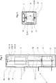
- An elevator installation 1 is, as in Fig. 1 visible in a building or grown and it is used to transport people or goods within the building.
- the elevator installation includes an elevator car 2, which can move up and down along guide rails 7.
- a drive 6 serves to drive and hold the elevator car 2.
- the drive 6 is arranged, for example, in the upper area of the building and the car 2 hangs with suspension elements 4, for example suspension ropes or carrying belts, on the drive 6 or on traction sheaves 6.2 of the drive 6.
- the support means 4 are further guided via the traction sheaves 6.2 to a counterweight 3.
- a drive motor 6.1 of the drive 6 drives the traction sheaves 6.2 and thus the support means 4 and thus the elevator car 2 and the counterweight 3.
- a drive brake 6.3 brakes the traction sheaves 6.2 if necessary or keeps them in a rest position.
- the drive 6 can of course also be arranged at a different location in the building, or in the area of the car 2 or the counterweight 3.
- the support means 4 are guided over Tragstoffumlenkrollen 5 of the elevator car 2.
- the elevator car 2 and, of course, the counterweight 3 is 2: 1 suspended and driven.
- a movement sensor 14 for detecting a driving speed or a travel path of the elevator car is arranged.
- the signals of the motion sensor 14 are forwarded to a safety device 12.
- the elevator installation 1 is controlled by an elevator control 11.
- the elevator control 11 accepts user requests, optimizes the operation of the elevator installation and controls, usually via a drive control 10, the drive 6.
- the elevator control 11 or the drive control 10 also monitors the safety state of the elevator system and interrupts the driving operation when an unsafe operating state occurs.
- This monitoring is usually carried out with the use of an elevator safety circuit 28 in which all safety-related functions are integrated.
- an elevator safety circuit 28 in which all safety-related functions are integrated.
- bay door contacts are included, which monitor a correct closure of the shaft doors and it also monitors, for example, limit positions of the car body 2, 3 in the elevator shaft.
- An interruption of the elevator safety circuit 28 causes a shutdown of the drive motor 6.1 and an actuation of the drive brake 6.3 which the elevator system 1 in the rule, that is, at the proper function of the support and drive system, is stopped.
- the elevator car 2 and in case of need also the counterweight 3 are further equipped with a braking system which is suitable for the elevator car 2, or the counterweight 3, in an unexpected movement or overspeed, even in case of failure of the supporting and driving system secure and / or delay.
- the brake system comprises in the example two identical safety brakes, or safety gears 8 which are attached to both sides of the elevator car 2, and the counterweight 3 to the same.
- the safety gears 8 are arranged in the example below the elevator car 2 and they are electrically controlled by a brake control 9.
- This brake control 9 is connected to the safety device 12 of the elevator installation, which monitors the movement of the elevator car 2, or the counterweight 3 and, if necessary, causes the actuation of the safety gears 8 or interrupts the elevator safety circuit 28.
- the brake control 9 and the safety device 12 may be separate components, they may of course also be assembled in a functional group or even integrated into an elevator or drive control 11, 10.
- a mechanical speed limiter as it is usually used, can be omitted since the safety device 12 takes over its task.
- appropriate design of the safety gears 8 for example, by redundant brake circuits, appropriate control algorithms and reset functions can possibly account for the drive brake 6.3 and the elevator safety circuit 28 can act directly on the brake control 9.
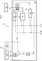
- Fig. 2 shows the elevator system of Fig. 1 in a schematic plan view.
- the brake system includes the two safety gears 8.
- the two safety gears 8 are electrically or mechanically coupled, so that the two safety gears 8 are actuated together. This avoids unintentional unilateral braking or catching.
- the two safety gears 8 are preferably of identical or mirror-symmetrical design and they act on the on both sides of the car. 2 arranged guide rails 7 a.
- the safety device 12 which monitors the movement of the elevator car, includes in a first embodiment, as in FIG. 3 illustrated a first motion sensor 13 for detecting an acceleration AS of the elevator car 2.
- This first motion sensor 13 is disposed at the elevator car 2, or attached to this, so that it can detect at least the accelerations of the elevator car in the vertical direction. From this acceleration, an integration routine 15 calculates an integrated vehicle speed VS, whereby, of course, the acceleration is corrected by the amount of gravitational acceleration.
- the safety device 12 includes a second motion sensor 14 with reference to FIGS FIG. 1 is attached to one of Tragstoffumlenkrollen 5 and, in one embodiment, by means of an increment counter 14.2 detects angular movements of Tragstoffumlenkrolle 5.
- a travel path SM is detected therefrom, and a travel speed VM is derived from this travel path SM by means of a distance differential calculator 14.3.
- a tachometer 14.1 can be used which directly detects the travel speed VM, as shown in FIG. 3 is shown in dashed lines.
- a differential routine 17 calculates a derived acceleration AM from the vehicle speed VM detected or derived by the second motion sensor 14.
- the signals from acceleration sensors as used to detect accelerations of the elevator car 2, have system-related minor inaccuracies. This leads via the integration to a summation of these inaccuracies, which over a longer time leads to a falsification of the result.
- a new integration cycle is performed second motion sensor detected travel speed VM as start size, started.
- the integration routine 15 is accompanied by a reset logic 16.
- the reset logic 16 controls the integration course of the integration routine 15 and feeds the detected by the second motion sensor 14 Driving speed VM in each case as the starting size of an integration cycle.
- a first comparison routine 21 compares the integrated vehicle speed VS of the first motion sensor 13 with the detected vehicle speed VM and generates a warning signal R1 to the reset logic 16 when a difference dV between the two vehicle speeds VS, VM has a predetermined value of, for example, about 5% of a nominal speed exceeds.
- a new integration cycle is started, in which case the travel speed VM detected by the second movement sensor is set as the start variable of the new integration cycle. This basically compensates drift in principle.
- the comparison routine 21 operates in long time intervals of, for example, about 500 milliseconds. If now the comparison routine 21 determines that the difference dV within this time interval becomes large, for example more than 10% of the nominal speed, a safety measure 27 is triggered. In a first stage of the elevator safety circuit 28 is interrupted and thus shut down the elevator system. If the difference dV within this time interval is even greater, for example more than 15% of the nominal speed, a brake control 9 for activating the safety gears is activated directly.
- a second comparison routine 22 checks a correct function of the first and second motion sensors 13, 14 by comparing the acceleration AM derived from the second motion sensor 14 with the acceleration AS detected by the first motion sensor 13 and naturally acceleration-corrected acceleration AS.
- This second comparison routine 22 operates in contrast to the first comparison routine 21 with high clock frequencies.
- a working time interval of the second comparison routine 22 is, for example, about 10 milliseconds.
- the OK signal is stopped, whereupon the reset logic 16 uses the respective larger of the two travel speeds VS, VM for a possibly new integration cycle.
- the safety measure 27 is selectively initialized, depending on the size of a difference between the two accelerations AM, AS, only the elevator safety circuit 28 is interrupted or, if necessary time-delayed, the brake control 9 is driven.
- the values given in the examples are merely exemplary. Depending on the sensors used, travel speed, etc., the time values, difference values and other values are defined.
- the elevator safety circuit 28 is interrupted as the first safety measure 27 when the so-called nominal speed of the elevator installation is exceeded by about 10%, or the safety gear 8 is actuated when the nominal speed is exceeded by more than 15%.
- the accelerations AM, AS the function of the two motion sensors is checked and monitored and, by means of sporadic adjustment of the travel speeds VM, VS, a drift of the integrated vehicle speed VS is compensated and a function of calculation routines is checked.
- the driving speed of the elevator car is reliably monitored.
- the calculation routines 15, 17, 14.3, the comparison routines 21, 22 and the monitoring module 18 are arranged on a board or on a processor unit 25.
- the first motion sensor 13 can also be a component of this processor unit 25, and the entire safety device 12 can be located in the region of the suspension element deflection rollers 5 (see FIG FIGS. 1 and 2 ) can be arranged.
- the arrangements can be chosen differently.
- the second motion sensor 14 together with the differential routine 17 may form a processor unit and the remaining components such as integration routine 15, the comparison routines 21, 22 and the monitoring module 18 may be combined in another processor unit.
- the safety device 12 includes a second monitoring module 19 which compares the vehicle speed VM detected or derived from the second motion sensor 14 with a permissible limit speed VG2 and, analogously to the first monitoring module 18, the safety measure 27 triggers when the permissible limit speed is exceeded.
- the permissible limit speed VG2 is set to be identical to the limit speed VG.
- the safety device 12 includes a fourth comparison routine 24, which compares in partial analogy to the first comparison routine 21, the detected by the second motion sensor 14 or derived vehicle speed VM with the integrated vehicle speed VS of the first motion sensor 13. This fourth comparison routine 24 likewise triggers, like the first comparison routine 21, a safety measure 27 when a difference within a set time interval becomes large.
- the integration routine 15 with associated reset logic 16, the first and second comparison routine 21, 22 and the monitoring module 18 are arranged on a first processor unit 25.
- This first processor unit 25 is assigned to the first motion sensor 13, or the first motion sensor 13 is integrated into the first processor unit 25.
- the remaining components such as the differential routine 17, the monitoring module 19 and the fourth comparison routine 24 are arranged on a second processor unit 26 in connection with the displacement sensor 14.2 and the path-Diffentiator 14, 3 or the speedometer 14.1.
- the security of this safety device with two processor units 25, 26 is particularly reliable, since important functions are processed redundantly and the two processor units 25, 26 can independently initialize safety measures 27.
- FIG. 5 Another execution, as in FIG. 5 in addition to the previous embodiments, further includes a third monitoring module 20, which is arranged at the first processor unit 25 and which compares the detected by the first motion sensor 13 acceleration AS of the elevator car with at least one predetermined limit acceleration AG and which when exceeding the predetermined Grenzbevantung AG triggers a safety measure 27.
- This third monitoring module 20 is primarily intended to quickly detect a possible free fall or crash of an elevator car.
- a third comparison routine 23 is provided, which is arranged at the second processor unit 26 and which, in analogy to the second comparison routine 22, checks a correct function of the first and the second motion sensor 13, 14 by detecting the movement detected by the first movement sensor 13
- earth acceleration-corrected acceleration AS is compared with the acceleration AM derived from the second motion sensor 14 and triggers any safety measures if the comparison results in large deviations.
- the illustrated embodiments can be varied by the person skilled in the art. Depending on the required security level, redundant comparison routines 23, 24 or the redundant monitoring module 19 may be omitted. If necessary, the entire safety device 12 can be duplicated in one of the embodiments or a variation thereof, so that a safety device is arranged at a first suspension element deflection roller 5.1 and a second safety device at a second suspension element deflection roller 5.2. By this redundant arrangement, a security of the entire system is improved.
- absolute position systems or other displacement measuring systems can of course also be used instead of the incremental sensors or tachogenerators mentioned in the exemplary embodiments.
- the method and the safety device in the application for monitoring the movements of the elevator car are shown and explained. In the same way, the method or the device can of course also be used on the counterweight.
Landscapes
- Engineering & Computer Science (AREA)
- Automation & Control Theory (AREA)
- Physics & Mathematics (AREA)
- General Physics & Mathematics (AREA)
- Computer Networks & Wireless Communication (AREA)
- Maintenance And Inspection Apparatuses For Elevators (AREA)
- Indicating And Signalling Devices For Elevators (AREA)
Priority Applications (2)
| Application Number | Priority Date | Filing Date | Title |
|---|---|---|---|
| EP13779813.8A EP2909122B1 (de) | 2012-10-18 | 2013-10-18 | Sicherheitseinrichtung einer aufzugsanlage |
| PL13779813T PL2909122T3 (pl) | 2012-10-18 | 2013-10-18 | Urządzenie zabezpieczające instalacji dźwigowej |
Applications Claiming Priority (3)
| Application Number | Priority Date | Filing Date | Title |
|---|---|---|---|
| EP12189011 | 2012-10-18 | ||
| EP13779813.8A EP2909122B1 (de) | 2012-10-18 | 2013-10-18 | Sicherheitseinrichtung einer aufzugsanlage |
| PCT/EP2013/071865 WO2014060587A1 (de) | 2012-10-18 | 2013-10-18 | Sicherheitseinrichtung einer aufzugsanlage |
Publications (2)
| Publication Number | Publication Date |
|---|---|
| EP2909122A1 EP2909122A1 (de) | 2015-08-26 |
| EP2909122B1 true EP2909122B1 (de) | 2018-05-23 |
Family
ID=47018907
Family Applications (1)
| Application Number | Title | Priority Date | Filing Date |
|---|---|---|---|
| EP13779813.8A Not-in-force EP2909122B1 (de) | 2012-10-18 | 2013-10-18 | Sicherheitseinrichtung einer aufzugsanlage |
Country Status (12)
| Country | Link |
|---|---|
| US (1) | US9975732B2 (da) |
| EP (1) | EP2909122B1 (da) |
| CN (1) | CN104718148B (da) |
| AU (1) | AU2013333826B2 (da) |
| BR (1) | BR112015008192A2 (da) |
| CA (1) | CA2886754C (da) |
| DK (1) | DK2909122T3 (da) |
| ES (1) | ES2673229T3 (da) |
| PL (1) | PL2909122T3 (da) |
| PT (1) | PT2909122T (da) |
| SG (1) | SG11201502862VA (da) |
| WO (1) | WO2014060587A1 (da) |
Families Citing this family (17)
| Publication number | Priority date | Publication date | Assignee | Title |
|---|---|---|---|---|
| WO2014060587A1 (de) * | 2012-10-18 | 2014-04-24 | Inventio Ag | Sicherheitseinrichtung einer aufzugsanlage |
| WO2014067814A1 (de) * | 2012-10-30 | 2014-05-08 | Inventio Ag | Bewegungs-überwachungssystem einer aufzugsanlage |
| WO2016096320A1 (de) * | 2014-12-17 | 2016-06-23 | Inventio Ag | Aufzugsanlage mit einem bremssystem |
| AU2016286288B2 (en) | 2015-06-30 | 2019-08-15 | Inventio Ag | Monitoring device for a lift system |
| KR102633879B1 (ko) * | 2015-09-25 | 2024-02-05 | 인벤티오 아게 | 엘리베이터 시스템을 위한 모니터링 디바이스 |
| CN109071166B (zh) * | 2016-03-30 | 2021-05-25 | 通力股份公司 | 用于验证电梯轿厢的速度数据对电梯轿厢进行超速监控的方法、安全控制单元和电梯系统 |
| US10252884B2 (en) | 2016-04-05 | 2019-04-09 | Otis Elevator Company | Wirelessly powered elevator electronic safety device |
| EP3257799B1 (en) * | 2016-06-17 | 2022-02-23 | KONE Corporation | Redundant safety circuit |
| US10889467B2 (en) * | 2018-05-08 | 2021-01-12 | Otis Elevator Company | Synchronization based on distance of magnet assembly to rail |
| EP3608274A1 (en) | 2018-08-10 | 2020-02-12 | Otis Elevator Company | Enhancing the transport capacity of an elevator system |
| CN109650206B (zh) * | 2019-01-24 | 2024-04-05 | 大连特种设备检验检测研究院有限公司 | 一种电梯负载安全制动试验装置 |
| EP3892579A1 (en) * | 2020-04-06 | 2021-10-13 | Otis Elevator Company | Elevator safety systems |
| CN112061916B (zh) * | 2020-07-22 | 2022-06-28 | 上海新时达电气股份有限公司 | 电梯电路板的防伪方法 |
| BR112023003918A2 (pt) * | 2020-09-04 | 2023-04-04 | Inventio Ag | Unidade de controle |
| CN113011291B (zh) * | 2021-03-03 | 2024-08-09 | 上海商汤智能科技有限公司 | 事件检测方法及装置、电子设备和存储介质 |
| CN116045427B (zh) * | 2023-03-30 | 2023-10-10 | 福建省特种设备检验研究院 | 基于智能决策的电梯轿厢空气净化系统 |
| EP4553025A1 (de) * | 2023-11-09 | 2025-05-14 | Cedes AG | Sicherheitssystem für einen aufzug |
Family Cites Families (13)
| Publication number | Priority date | Publication date | Assignee | Title |
|---|---|---|---|---|
| JPH10132843A (ja) | 1996-10-25 | 1998-05-22 | Murata Mfg Co Ltd | 速度演算装置 |
| US6173813B1 (en) | 1998-12-23 | 2001-01-16 | Otis Elevator Company | Electronic control for an elevator braking system |
| PL2189410T3 (pl) | 2004-06-02 | 2014-05-30 | Inventio Ag | Nadzorowanie windy |
| US7143001B2 (en) | 2004-07-21 | 2006-11-28 | Rockwell Automation Technologies, Inc. | Method for monitoring operating characteristics of a single axis machine |
| FI118639B (fi) * | 2006-12-08 | 2008-01-31 | Kone Corp | Hissijärjestelmä |
| WO2009013114A1 (de) | 2007-07-20 | 2009-01-29 | Inventio Ag | Verfahren zur ermittlung der geschwindigkeit einer aufzugskabine und eine steuereinheit zur durchführung dieses verfahrens |
| JP4812037B2 (ja) * | 2007-07-23 | 2011-11-09 | 株式会社日立製作所 | エレベーター乗りかごの速度検出装置およびエレベーターの安全装置 |
| KR101334712B1 (ko) * | 2009-03-16 | 2013-11-29 | 오티스 엘리베이터 컴파니 | 과가속 및 과속 검출 및 처리 시스템 |
| KR101706883B1 (ko) * | 2011-04-01 | 2017-02-14 | 미쓰비시덴키 가부시키가이샤 | 엘리베이터 장치 |
| HUE027471T2 (en) * | 2012-01-25 | 2016-09-28 | Inventio Ag | Procedure and control device for monitoring the progress of a lift cabin |
| WO2014060587A1 (de) * | 2012-10-18 | 2014-04-24 | Inventio Ag | Sicherheitseinrichtung einer aufzugsanlage |
| JPWO2014097373A1 (ja) * | 2012-12-17 | 2017-01-12 | 三菱電機株式会社 | エレベータ装置 |
| EP2848568B1 (en) * | 2013-09-17 | 2022-07-20 | KONE Corporation | A method and an elevator for stopping an elevator car using elevator drive |
-
2013
- 2013-10-18 WO PCT/EP2013/071865 patent/WO2014060587A1/de not_active Ceased
- 2013-10-18 PL PL13779813T patent/PL2909122T3/pl unknown
- 2013-10-18 ES ES13779813.8T patent/ES2673229T3/es active Active
- 2013-10-18 BR BR112015008192A patent/BR112015008192A2/pt active Search and Examination
- 2013-10-18 US US14/436,501 patent/US9975732B2/en active Active
- 2013-10-18 PT PT13779813T patent/PT2909122T/pt unknown
- 2013-10-18 DK DK13779813.8T patent/DK2909122T3/da active
- 2013-10-18 CN CN201380053838.0A patent/CN104718148B/zh not_active Expired - Fee Related
- 2013-10-18 AU AU2013333826A patent/AU2013333826B2/en not_active Ceased
- 2013-10-18 EP EP13779813.8A patent/EP2909122B1/de not_active Not-in-force
- 2013-10-18 CA CA2886754A patent/CA2886754C/en not_active Expired - Fee Related
- 2013-10-18 SG SG11201502862VA patent/SG11201502862VA/en unknown
Non-Patent Citations (1)
| Title |
|---|
| None * |
Also Published As
| Publication number | Publication date |
|---|---|
| BR112015008192A2 (pt) | 2017-07-04 |
| CA2886754A1 (en) | 2014-04-24 |
| SG11201502862VA (en) | 2015-05-28 |
| CN104718148B (zh) | 2016-10-12 |
| CN104718148A (zh) | 2015-06-17 |
| EP2909122A1 (de) | 2015-08-26 |
| US20150274487A1 (en) | 2015-10-01 |
| HK1209404A1 (en) | 2016-04-01 |
| US9975732B2 (en) | 2018-05-22 |
| WO2014060587A1 (de) | 2014-04-24 |
| AU2013333826B2 (en) | 2016-12-15 |
| CA2886754C (en) | 2020-09-29 |
| PT2909122T (pt) | 2018-10-08 |
| PL2909122T3 (pl) | 2018-10-31 |
| AU2013333826A1 (en) | 2015-05-07 |
| ES2673229T3 (es) | 2018-06-20 |
| DK2909122T3 (da) | 2018-08-20 |
Similar Documents
| Publication | Publication Date | Title |
|---|---|---|
| EP2909122B1 (de) | Sicherheitseinrichtung einer aufzugsanlage | |
| EP2807103B1 (de) | Verfahren und steuereinrichtung zur überwachung von fahrbewegungen einer aufzugskabine | |
| EP3209589B1 (de) | Aufzug mit einem dezentralen elektronischen sicherheitssystem | |
| EP2516305B1 (de) | Verfahren und vorrichtung zur bestimmung der bewegung und/oder der position einer aufzugskabine | |
| DE102012003178B4 (de) | Einrichtung zur Überwachung der Funktion einer Rolltreppe oder eines Rollsteiges | |
| EP2170753B1 (de) | Aufzugsanlage mit einer aufzugkabine und einer bremseinrichtung zum stillsetzen der aufzugkabine im sonderbetrieb und ein verfahren zum stillsetzen einer aufzugkabine im sonderbetrieb | |
| WO2014067814A1 (de) | Bewegungs-überwachungssystem einer aufzugsanlage | |
| DE102007006316B3 (de) | Vorrichtung und Verfahren zur Seillageüberwachung einer seilbetriebenen Transportanlage und seilbetriebene Transportanlage | |
| EP2457860B1 (de) | Sicherheitseinrichtung für einen Aufzug | |
| EP3384354B1 (de) | Elektrisches antriebssystem mit schlupfbehafteter kopplungseinheit | |
| EP2017524A2 (de) | Lichtgitter | |
| DE10392710T5 (de) | Aufzugsicherheitssystem | |
| EP2567923A1 (de) | Redundante Schachtkopierung | |
| DE102019007039A1 (de) | Steuervorrichtung und Verfahren zum Einrücken einer Fangvorrichtung | |
| EP2043935B1 (de) | Positionsdetektor einer Aufzugskabine | |
| DE102012106018A1 (de) | Verfahren und Vorrichtung zum frühzeitigen Auslösen einer Aufzugsbremse | |
| DE102004058471A1 (de) | Sicherheitseinrichtung für eine automatisiert arbeitende Anlage mit zumindest einem automatisiert bewegbaren Anlagenteil | |
| EP2701962B1 (de) | Schienenfahrzeug mit einer heissläuferüberwachung | |
| DE102016225079A1 (de) | Tor mit einer Absturzsicherung | |
| DE202004010720U1 (de) | Steuerungssystem für Aufzüge | |
| EP1516842A2 (de) | Steuerungs- und Regelungseinrichtung für einen Aufzug | |
| WO2007068550A1 (de) | Überwachungseinrichtung bzw. überwachungsverfahren für eine antriebseinrichtung | |
| DE2039527C3 (de) | Schaltungsanordnung zur Erfassung des Schleuderns und Gleitens der Triebachsen von Triebfahrzeugen | |
| WO2014005833A1 (de) | Regelvorrichtung zum regeln der beschleunigung einer in vertikaler richtung bewegten transporteinrichtung |
Legal Events
| Date | Code | Title | Description |
|---|---|---|---|
| PUAI | Public reference made under article 153(3) epc to a published international application that has entered the european phase |
Free format text: ORIGINAL CODE: 0009012 |
|
| 17P | Request for examination filed |
Effective date: 20150327 |
|
| AK | Designated contracting states |
Kind code of ref document: A1 Designated state(s): AL AT BE BG CH CY CZ DE DK EE ES FI FR GB GR HR HU IE IS IT LI LT LU LV MC MK MT NL NO PL PT RO RS SE SI SK SM TR |
|
| AX | Request for extension of the european patent |
Extension state: BA ME |
|
| DAX | Request for extension of the european patent (deleted) | ||
| 17Q | First examination report despatched |
Effective date: 20160624 |
|
| GRAP | Despatch of communication of intention to grant a patent |
Free format text: ORIGINAL CODE: EPIDOSNIGR1 |
|
| INTG | Intention to grant announced |
Effective date: 20171219 |
|
| GRAS | Grant fee paid |
Free format text: ORIGINAL CODE: EPIDOSNIGR3 |
|
| GRAA | (expected) grant |
Free format text: ORIGINAL CODE: 0009210 |
|
| AK | Designated contracting states |
Kind code of ref document: B1 Designated state(s): AL AT BE BG CH CY CZ DE DK EE ES FI FR GB GR HR HU IE IS IT LI LT LU LV MC MK MT NL NO PL PT RO RS SE SI SK SM TR |
|
| REG | Reference to a national code |
Ref country code: GB Ref legal event code: FG4D Free format text: NOT ENGLISH |
|
| REG | Reference to a national code |
Ref country code: CH Ref legal event code: EP |
|
| REG | Reference to a national code |
Ref country code: IE Ref legal event code: FG4D Free format text: LANGUAGE OF EP DOCUMENT: GERMAN |
|
| REG | Reference to a national code |
Ref country code: AT Ref legal event code: REF Ref document number: 1001364 Country of ref document: AT Kind code of ref document: T Effective date: 20180615 |
|
| REG | Reference to a national code |
Ref country code: ES Ref legal event code: FG2A Ref document number: 2673229 Country of ref document: ES Kind code of ref document: T3 Effective date: 20180620 |
|
| REG | Reference to a national code |
Ref country code: DE Ref legal event code: R096 Ref document number: 502013010200 Country of ref document: DE |
|
| REG | Reference to a national code |
Ref country code: SE Ref legal event code: TRGR |
|
| REG | Reference to a national code |
Ref country code: DK Ref legal event code: T3 Effective date: 20180814 |
|
| REG | Reference to a national code |
Ref country code: NL Ref legal event code: FP |
|
| REG | Reference to a national code |
Ref country code: PT Ref legal event code: SC4A Ref document number: 2909122 Country of ref document: PT Date of ref document: 20181008 Kind code of ref document: T Free format text: AVAILABILITY OF NATIONAL TRANSLATION Effective date: 20180814 |
|
| REG | Reference to a national code |
Ref country code: LT Ref legal event code: MG4D |
|
| REG | Reference to a national code |
Ref country code: FR Ref legal event code: PLFP Year of fee payment: 6 |
|
| PG25 | Lapsed in a contracting state [announced via postgrant information from national office to epo] |
Ref country code: NO Free format text: LAPSE BECAUSE OF FAILURE TO SUBMIT A TRANSLATION OF THE DESCRIPTION OR TO PAY THE FEE WITHIN THE PRESCRIBED TIME-LIMIT Effective date: 20180823 Ref country code: BG Free format text: LAPSE BECAUSE OF FAILURE TO SUBMIT A TRANSLATION OF THE DESCRIPTION OR TO PAY THE FEE WITHIN THE PRESCRIBED TIME-LIMIT Effective date: 20180823 Ref country code: LT Free format text: LAPSE BECAUSE OF FAILURE TO SUBMIT A TRANSLATION OF THE DESCRIPTION OR TO PAY THE FEE WITHIN THE PRESCRIBED TIME-LIMIT Effective date: 20180523 |
|
| PG25 | Lapsed in a contracting state [announced via postgrant information from national office to epo] |
Ref country code: LV Free format text: LAPSE BECAUSE OF FAILURE TO SUBMIT A TRANSLATION OF THE DESCRIPTION OR TO PAY THE FEE WITHIN THE PRESCRIBED TIME-LIMIT Effective date: 20180523 Ref country code: RS Free format text: LAPSE BECAUSE OF FAILURE TO SUBMIT A TRANSLATION OF THE DESCRIPTION OR TO PAY THE FEE WITHIN THE PRESCRIBED TIME-LIMIT Effective date: 20180523 Ref country code: GR Free format text: LAPSE BECAUSE OF FAILURE TO SUBMIT A TRANSLATION OF THE DESCRIPTION OR TO PAY THE FEE WITHIN THE PRESCRIBED TIME-LIMIT Effective date: 20180824 Ref country code: HR Free format text: LAPSE BECAUSE OF FAILURE TO SUBMIT A TRANSLATION OF THE DESCRIPTION OR TO PAY THE FEE WITHIN THE PRESCRIBED TIME-LIMIT Effective date: 20180523 |
|
| PG25 | Lapsed in a contracting state [announced via postgrant information from national office to epo] |
Ref country code: EE Free format text: LAPSE BECAUSE OF FAILURE TO SUBMIT A TRANSLATION OF THE DESCRIPTION OR TO PAY THE FEE WITHIN THE PRESCRIBED TIME-LIMIT Effective date: 20180523 Ref country code: SK Free format text: LAPSE BECAUSE OF FAILURE TO SUBMIT A TRANSLATION OF THE DESCRIPTION OR TO PAY THE FEE WITHIN THE PRESCRIBED TIME-LIMIT Effective date: 20180523 Ref country code: CZ Free format text: LAPSE BECAUSE OF FAILURE TO SUBMIT A TRANSLATION OF THE DESCRIPTION OR TO PAY THE FEE WITHIN THE PRESCRIBED TIME-LIMIT Effective date: 20180523 Ref country code: RO Free format text: LAPSE BECAUSE OF FAILURE TO SUBMIT A TRANSLATION OF THE DESCRIPTION OR TO PAY THE FEE WITHIN THE PRESCRIBED TIME-LIMIT Effective date: 20180523 |
|
| REG | Reference to a national code |
Ref country code: DE Ref legal event code: R097 Ref document number: 502013010200 Country of ref document: DE |
|
| PG25 | Lapsed in a contracting state [announced via postgrant information from national office to epo] |
Ref country code: SM Free format text: LAPSE BECAUSE OF FAILURE TO SUBMIT A TRANSLATION OF THE DESCRIPTION OR TO PAY THE FEE WITHIN THE PRESCRIBED TIME-LIMIT Effective date: 20180523 |
|
| PLBE | No opposition filed within time limit |
Free format text: ORIGINAL CODE: 0009261 |
|
| STAA | Information on the status of an ep patent application or granted ep patent |
Free format text: STATUS: NO OPPOSITION FILED WITHIN TIME LIMIT |
|
| 26N | No opposition filed |
Effective date: 20190226 |
|
| PG25 | Lapsed in a contracting state [announced via postgrant information from national office to epo] |
Ref country code: SI Free format text: LAPSE BECAUSE OF FAILURE TO SUBMIT A TRANSLATION OF THE DESCRIPTION OR TO PAY THE FEE WITHIN THE PRESCRIBED TIME-LIMIT Effective date: 20180523 |
|
| PG25 | Lapsed in a contracting state [announced via postgrant information from national office to epo] |
Ref country code: MC Free format text: LAPSE BECAUSE OF FAILURE TO SUBMIT A TRANSLATION OF THE DESCRIPTION OR TO PAY THE FEE WITHIN THE PRESCRIBED TIME-LIMIT Effective date: 20180523 |
|
| REG | Reference to a national code |
Ref country code: IE Ref legal event code: MM4A |
|
| PG25 | Lapsed in a contracting state [announced via postgrant information from national office to epo] |
Ref country code: IE Free format text: LAPSE BECAUSE OF NON-PAYMENT OF DUE FEES Effective date: 20181018 |
|
| PG25 | Lapsed in a contracting state [announced via postgrant information from national office to epo] |
Ref country code: AL Free format text: LAPSE BECAUSE OF FAILURE TO SUBMIT A TRANSLATION OF THE DESCRIPTION OR TO PAY THE FEE WITHIN THE PRESCRIBED TIME-LIMIT Effective date: 20180523 |
|
| PGFP | Annual fee paid to national office [announced via postgrant information from national office to epo] |
Ref country code: PL Payment date: 20190923 Year of fee payment: 7 Ref country code: LU Payment date: 20191021 Year of fee payment: 7 |
|
| PG25 | Lapsed in a contracting state [announced via postgrant information from national office to epo] |
Ref country code: MT Free format text: LAPSE BECAUSE OF FAILURE TO SUBMIT A TRANSLATION OF THE DESCRIPTION OR TO PAY THE FEE WITHIN THE PRESCRIBED TIME-LIMIT Effective date: 20180523 |
|
| PGFP | Annual fee paid to national office [announced via postgrant information from national office to epo] |
Ref country code: SE Payment date: 20191021 Year of fee payment: 7 Ref country code: FI Payment date: 20191022 Year of fee payment: 7 Ref country code: NL Payment date: 20191021 Year of fee payment: 7 Ref country code: PT Payment date: 20191016 Year of fee payment: 7 |
|
| PGFP | Annual fee paid to national office [announced via postgrant information from national office to epo] |
Ref country code: BE Payment date: 20191021 Year of fee payment: 7 Ref country code: ES Payment date: 20191126 Year of fee payment: 7 Ref country code: DK Payment date: 20191023 Year of fee payment: 7 |
|
| PGFP | Annual fee paid to national office [announced via postgrant information from national office to epo] |
Ref country code: TR Payment date: 20191015 Year of fee payment: 7 Ref country code: CH Payment date: 20191021 Year of fee payment: 7 Ref country code: AT Payment date: 20191022 Year of fee payment: 7 |
|
| PG25 | Lapsed in a contracting state [announced via postgrant information from national office to epo] |
Ref country code: HU Free format text: LAPSE BECAUSE OF FAILURE TO SUBMIT A TRANSLATION OF THE DESCRIPTION OR TO PAY THE FEE WITHIN THE PRESCRIBED TIME-LIMIT; INVALID AB INITIO Effective date: 20131018 Ref country code: MK Free format text: LAPSE BECAUSE OF NON-PAYMENT OF DUE FEES Effective date: 20180523 Ref country code: CY Free format text: LAPSE BECAUSE OF FAILURE TO SUBMIT A TRANSLATION OF THE DESCRIPTION OR TO PAY THE FEE WITHIN THE PRESCRIBED TIME-LIMIT Effective date: 20180523 |
|
| PG25 | Lapsed in a contracting state [announced via postgrant information from national office to epo] |
Ref country code: IS Free format text: LAPSE BECAUSE OF FAILURE TO SUBMIT A TRANSLATION OF THE DESCRIPTION OR TO PAY THE FEE WITHIN THE PRESCRIBED TIME-LIMIT Effective date: 20180923 |
|
| REG | Reference to a national code |
Ref country code: DK Ref legal event code: EBP Effective date: 20201031 |
|
| REG | Reference to a national code |
Ref country code: CH Ref legal event code: PL Ref country code: FI Ref legal event code: MAE |
|
| REG | Reference to a national code |
Ref country code: SE Ref legal event code: EUG |
|
| REG | Reference to a national code |
Ref country code: NL Ref legal event code: MM Effective date: 20201101 |
|
| REG | Reference to a national code |
Ref country code: AT Ref legal event code: MM01 Ref document number: 1001364 Country of ref document: AT Kind code of ref document: T Effective date: 20201018 |
|
| PG25 | Lapsed in a contracting state [announced via postgrant information from national office to epo] |
Ref country code: LU Free format text: LAPSE BECAUSE OF NON-PAYMENT OF DUE FEES Effective date: 20201018 |
|
| REG | Reference to a national code |
Ref country code: BE Ref legal event code: MM Effective date: 20201031 |
|
| PG25 | Lapsed in a contracting state [announced via postgrant information from national office to epo] |
Ref country code: NL Free format text: LAPSE BECAUSE OF NON-PAYMENT OF DUE FEES Effective date: 20201101 Ref country code: PT Free format text: LAPSE BECAUSE OF NON-PAYMENT OF DUE FEES Effective date: 20210419 Ref country code: FI Free format text: LAPSE BECAUSE OF NON-PAYMENT OF DUE FEES Effective date: 20201018 |
|
| PG25 | Lapsed in a contracting state [announced via postgrant information from national office to epo] |
Ref country code: SE Free format text: LAPSE BECAUSE OF NON-PAYMENT OF DUE FEES Effective date: 20201019 Ref country code: LI Free format text: LAPSE BECAUSE OF NON-PAYMENT OF DUE FEES Effective date: 20201031 Ref country code: AT Free format text: LAPSE BECAUSE OF NON-PAYMENT OF DUE FEES Effective date: 20201018 Ref country code: BE Free format text: LAPSE BECAUSE OF NON-PAYMENT OF DUE FEES Effective date: 20201031 Ref country code: CH Free format text: LAPSE BECAUSE OF NON-PAYMENT OF DUE FEES Effective date: 20201031 |
|
| PG25 | Lapsed in a contracting state [announced via postgrant information from national office to epo] |
Ref country code: DK Free format text: LAPSE BECAUSE OF NON-PAYMENT OF DUE FEES Effective date: 20201031 |
|
| REG | Reference to a national code |
Ref country code: ES Ref legal event code: FD2A Effective date: 20220128 |
|
| PGFP | Annual fee paid to national office [announced via postgrant information from national office to epo] |
Ref country code: GB Payment date: 20211026 Year of fee payment: 9 |
|
| PGFP | Annual fee paid to national office [announced via postgrant information from national office to epo] |
Ref country code: IT Payment date: 20211020 Year of fee payment: 9 Ref country code: FR Payment date: 20211027 Year of fee payment: 9 |
|
| PG25 | Lapsed in a contracting state [announced via postgrant information from national office to epo] |
Ref country code: ES Free format text: LAPSE BECAUSE OF NON-PAYMENT OF DUE FEES Effective date: 20201019 |
|
| PG25 | Lapsed in a contracting state [announced via postgrant information from national office to epo] |
Ref country code: TR Free format text: LAPSE BECAUSE OF NON-PAYMENT OF DUE FEES Effective date: 20201018 |
|
| PG25 | Lapsed in a contracting state [announced via postgrant information from national office to epo] |
Ref country code: PL Free format text: LAPSE BECAUSE OF NON-PAYMENT OF DUE FEES Effective date: 20201018 |
|
| PGFP | Annual fee paid to national office [announced via postgrant information from national office to epo] |
Ref country code: DE Payment date: 20221028 Year of fee payment: 10 |
|
| GBPC | Gb: european patent ceased through non-payment of renewal fee |
Effective date: 20221018 |
|
| PG25 | Lapsed in a contracting state [announced via postgrant information from national office to epo] |
Ref country code: FR Free format text: LAPSE BECAUSE OF NON-PAYMENT OF DUE FEES Effective date: 20221031 |
|
| PG25 | Lapsed in a contracting state [announced via postgrant information from national office to epo] |
Ref country code: IT Free format text: LAPSE BECAUSE OF NON-PAYMENT OF DUE FEES Effective date: 20221018 Ref country code: GB Free format text: LAPSE BECAUSE OF NON-PAYMENT OF DUE FEES Effective date: 20221018 |
|
| REG | Reference to a national code |
Ref country code: DE Ref legal event code: R119 Ref document number: 502013010200 Country of ref document: DE |
|
| PG25 | Lapsed in a contracting state [announced via postgrant information from national office to epo] |
Ref country code: DE Free format text: LAPSE BECAUSE OF NON-PAYMENT OF DUE FEES Effective date: 20240501 |