EP2909496B1 - Turbo-tambour pour freins à tambour - Google Patents
Turbo-tambour pour freins à tambour Download PDFInfo
- Publication number
- EP2909496B1 EP2909496B1 EP13846980.4A EP13846980A EP2909496B1 EP 2909496 B1 EP2909496 B1 EP 2909496B1 EP 13846980 A EP13846980 A EP 13846980A EP 2909496 B1 EP2909496 B1 EP 2909496B1
- Authority
- EP
- European Patent Office
- Prior art keywords
- drum
- drum wall
- angled vanes
- radially angled
- attachment
- Prior art date
- Legal status (The legal status is an assumption and is not a legal conclusion. Google has not performed a legal analysis and makes no representation as to the accuracy of the status listed.)
- Active
Links
Images




Classifications
-
- F—MECHANICAL ENGINEERING; LIGHTING; HEATING; WEAPONS; BLASTING
- F16—ENGINEERING ELEMENTS AND UNITS; GENERAL MEASURES FOR PRODUCING AND MAINTAINING EFFECTIVE FUNCTIONING OF MACHINES OR INSTALLATIONS; THERMAL INSULATION IN GENERAL
- F16D—COUPLINGS FOR TRANSMITTING ROTATION; CLUTCHES; BRAKES
- F16D65/00—Parts or details
- F16D65/78—Features relating to cooling
- F16D65/82—Features relating to cooling for internally-engaging brakes
- F16D65/827—Features relating to cooling for internally-engaging brakes with open cooling system, e.g. cooled by air
-
- F—MECHANICAL ENGINEERING; LIGHTING; HEATING; WEAPONS; BLASTING
- F16—ENGINEERING ELEMENTS AND UNITS; GENERAL MEASURES FOR PRODUCING AND MAINTAINING EFFECTIVE FUNCTIONING OF MACHINES OR INSTALLATIONS; THERMAL INSULATION IN GENERAL
- F16D—COUPLINGS FOR TRANSMITTING ROTATION; CLUTCHES; BRAKES
- F16D65/00—Parts or details
- F16D65/02—Braking members; Mounting thereof
- F16D65/10—Drums for externally- or internally-engaging brakes
-
- F—MECHANICAL ENGINEERING; LIGHTING; HEATING; WEAPONS; BLASTING
- F16—ENGINEERING ELEMENTS AND UNITS; GENERAL MEASURES FOR PRODUCING AND MAINTAINING EFFECTIVE FUNCTIONING OF MACHINES OR INSTALLATIONS; THERMAL INSULATION IN GENERAL
- F16D—COUPLINGS FOR TRANSMITTING ROTATION; CLUTCHES; BRAKES
- F16D65/00—Parts or details
- F16D65/78—Features relating to cooling
-
- F—MECHANICAL ENGINEERING; LIGHTING; HEATING; WEAPONS; BLASTING
- F16—ENGINEERING ELEMENTS AND UNITS; GENERAL MEASURES FOR PRODUCING AND MAINTAINING EFFECTIVE FUNCTIONING OF MACHINES OR INSTALLATIONS; THERMAL INSULATION IN GENERAL
- F16D—COUPLINGS FOR TRANSMITTING ROTATION; CLUTCHES; BRAKES
- F16D65/00—Parts or details
- F16D65/02—Braking members; Mounting thereof
- F16D2065/13—Parts or details of discs or drums
- F16D2065/1304—Structure
- F16D2065/1328—Structure internal cavities, e.g. cooling channels
-
- F—MECHANICAL ENGINEERING; LIGHTING; HEATING; WEAPONS; BLASTING
- F16—ENGINEERING ELEMENTS AND UNITS; GENERAL MEASURES FOR PRODUCING AND MAINTAINING EFFECTIVE FUNCTIONING OF MACHINES OR INSTALLATIONS; THERMAL INSULATION IN GENERAL
- F16D—COUPLINGS FOR TRANSMITTING ROTATION; CLUTCHES; BRAKES
- F16D65/00—Parts or details
- F16D65/02—Braking members; Mounting thereof
- F16D2065/13—Parts or details of discs or drums
- F16D2065/1304—Structure
- F16D2065/1332—Structure external ribs, e.g. for cooling or reinforcement
Definitions
- the present invention relates to drum brakes for vehicles, and in particular to a brake drum having turbo-style vanes configured to reduce mechanical and/or thermal stresses on the drum.
- Drum brakes operate on the principles of converting kinetic energy into heat by creating friction when a set of brake shoes or pads press against an inner surface of a rotating brake drum.
- a common problem with such drum brakes is that uneven mechanical and thermal stresses and uneven cooling tends to cause premature drum cracking (heat cracks) and elevated brake temperatures tend to reduce lining life on brake shoes.
- US 1 966 169 A discloses a brake drum with ribs placed on an inner side of a drum body and with openings provided in the drum body between successive ribs for admitting air to the interior of the drum.
- US 1 865 311 A discloses a brake drum with radially oriented reinforcing ribs of a web pierced with openings, the ribs being placed on an outer surface of the web placed between a drum body and a flange with openings provided for admitting air to the interior of the drum.
- the drum includes an annular drum wall having an open end and an attachment end.
- the drum wall further includes an outer drum surface and an inner braking surface, each of which extends between the open end and the attachment end.
- the drum includes a hub attachment section that is attachable to an associated wheel hub wherein the hub attachment section extends radially about the attachment end of the drum wall forming a primary opening into which the associated wheel hub is receivable.
- the drum has a drum wall connection section extending between the attachment end of the drum wall and the hub attachment section, where the drum wall connection section exclusively consists of a plurality of radially angled vanes connecting the attachment end of the annular drum wall with the hub attachment section interspersed with a corresponding plurality of air openings, wherein each of the plurality of air openings is circumferentially enclosed at an inner radial end by the hub attachment section and at an outer radial end by the attachment end of the drum wall, wherein the plurality of radially angled vanes are curved such that a length of the plurality of radially angled vanes is greater than a radial width of the drum wall connection section .
- the plurality of radially angled vanes facilitate a radial expansion of the attachment end of the drum wall during operational rotation of the drum thereby reducing or eliminating an undesired 'bell mouthing' effect at the open end of the drum wall.
- the present disclosure relates generally to a drum brake assembly and a drum having an annular drum wall with an open end and an attachment end. More particularly, the present disclosure relates to a turbo-style drum having a drum wall connection section extending between the attachment end of the drum wall and a hub attachment section, where the drum wall connection section has a plurality of radially angled vanes interspersed with a corresponding plurality of air openings. Additional details of the preferred embodiments are set forth below with reference to the figures.
- the terms “a” or “an” shall mean one or more than one.
- the term “plurality” shall mean two or more than two.
- the term “another” is defined as a second or more.
- the terms “including” and/or “having” are open ended (e.g., comprising).
- the term “or” as used herein is to be interpreted as inclusive or meaning any one or any combination. Therefore, A, B or C means any of the following: A; B; C; A and B; A and C; B and C; A, B and C. An exception to this definition will occur only when a combination of elements, functions, steps or acts are in some way inherently mutually exclusive.
- a turbo-style drum 100 comprised of a annular drum wall 105 with an outer drum surface 110 and an inner braking surface 115 .
- the drum wall 105 extends between an open end 120 and an attachment end 125 .
- the drum of FIG. 1 further comprises a hub attachment section 130 having a plurality of lug holes 135 which are used to secure the drum 100 to a wheel hub (not shown).
- Drum 100 is also configured with a drum wall connection section 140 extending between the attachment end 125 of the drum wall 100 and the hub attachment section 130 , as shown in FIG. 1 .
- the hub attachment section 130 comprises a planar surface having an outer diameter from which the drum wall connection section 140 extends.
- the hub attachment section 130 further comprises an inner diameter forming a primary opening for receiving a wheel hub (not shown).
- the drum wall connection section 140 is further configured with a plurality of radially angled vanes 145 interspersed with a corresponding plurality of air openings 150 .
- the radially angled vanes 145 may be curved in a radially concave or a radially convex manner.
- the plurality of radially angled vanes 145 are oriented at an angle of between 20 degrees and 50 degrees as measured from an edge of the drum wall (i.e., attachment end 125 ) from which the plurality of radially angled vanes 145 extend.
- the particular angle may be selected based, at least in part, on the type of material used and/or the amount of desired cooling. In this fashion, the plurality of radially angled vanes 145 facilitate a radial expansion of the attachment end 125 of the drum wall 105 during operational rotation of the drum 100 .
- This radial expansion thereby serves to minimize a difference between a radial expansion of the attachment end 125 of the drum wall 105 and a radial expansion of the open end 120 of the drum wall 105 , thereby reducing or eliminating the undesired 'bell mouthing' effect.
- the plurality of radially angled vanes 145 may comprises at least two, in certain embodiment it may be preferable to have between 3 and 30 individual values encircling the hub attachment section 130 , as shown in FIG. 1 . However, it should similarly be appreciated that more or fewer individual vanes may be used consistently with the principles of the invention. Moreover, the number of vanes may depend, at least in part, on the expansion of the material during heating, as well as on the width of the vanes. The chosen ratio of vane-to-air space may also be dependent on the material.
- the plurality of radially angled vanes 145 may preferably be curved such that their respective lengths are greater than a radial width of the drum wall connection section 140 , thereby enabling additional expansion capacity during operational rotation of the drum 100 without creating large stresses due to differential in temperature from the hub mounting interface (e.g., hub attachment section 130 ) and high frictional areas (e.g., inner braking surface 115 ).
- the design of drum 100 tends to provide a longer drum life and lining life, as well as provide a lighter weight drum.
- the air openings 150 serve to facilitate air flow along the inner braking surface 115 of the drum 100 , thereby providing a desirable cooling effect as well.
- a stationary stator piece behind the radially angled vanes 145 may be used to pull air into the brake while the radially angled vanes 145 rotate and further circulate the air.
- the drum wall 105 may further comprise a squealer band 155 circumferentially positioned around the outer drum surface 110 .
- one or more optional strengthening ribs 160 may be positioned circumferentially around and parallel to the outer drum surface 110 , as shown in FIG. 1 , in order to provide further reinforcement to the drum wall 105 if needed.
- the drum of FIG. 1 may be cast as a unitary construction of a composite drum with steel shell, aluminum with an iron liner, or any other material(s) suitable for constructing drums of drum brakes.
- FIG. 2 depicted is a plan view of the brake drum 100 of FIG. 1 viewed from the end having the hub attachment section 130 and lug holes 135 .
- FIG. 2 similarly depicts the drum wall connection section 140 extending between the attachment end 125 of the drum wall 100 and the hub attachment section 130 .
- the plurality of radially angled vanes 145 interspersed with a corresponding plurality of air openings 150 .
- the radially angled vanes 145 may be oriented at an angle of between 20 degrees and 50 degrees as measured from an edge of the drum wall (i.e., attachment end 125 ) from which the plurality of radially angled vanes 145 extend.
- the plurality of radially angled vanes 145 are arranged such that they encircle the hub attachment section 130 , as shown in FIG. 2 .
- the plurality of radially angled vanes 145 may preferably be curved such that their respective lengths are greater than a radial width of the drum wall connection section 140 , thereby enabling additional expansion capacity during operational rotation of the drum 100 .
- the above-mentioned squealer band 155 circumferentially positioned around the outer surface of the drum 100 is also depicted in FIG. 2 .
- the optional strengthening ribs 160 positioned in this embodiment circumferentially around and parallel to the outer surface of the drum 100 , are also shown in FIG. 2 .
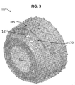
- FIG. 3 depicts a partially transparent view showing a brake shoe 165 disclosed along the inner braking surface 115 of the drum 100 .
- a stationary stator piece 170 may be disposed within the drum and behind the radially angled vanes 145 , either attached directly to the brake shoe 165 or not.
- the stator piece 170 may preferably contribute to pulling air into the brake while the radially angled vanes 145 rotate and further circulate the air.
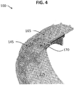
- FIG. 4 depicts an additionally broken out partial view of one embodiment for how the brake shoe 165 and stator piece 170 may be disposed along the inner braking surface 115 of the drum 100 .
- the stator piece 170 is preferably configured to have some number of external flow blades 175 1 - 175 n , and to be attached to a stationary part of the wheel end. In this fashion, the stator piece 170 may additionally serve to further direct the rotating air to create a positive directional flow through the turbo-style hub.
Landscapes
- Engineering & Computer Science (AREA)
- General Engineering & Computer Science (AREA)
- Mechanical Engineering (AREA)
- Braking Arrangements (AREA)
Claims (9)
- Tambour (100) pour un ensemble frein à tambour, le tambour comprenant :une paroi de tambour annulaire (105) ayant une extrémité ouverte (120) et une extrémité d'attache (125), dans lequel la paroi de tambour (105) comprend en outre une surface de tambour externe (110) et une surface de freinage interne (115) dont chacune s'étend entre l'extrémité ouverte (120) et l'extrémité d'attache (125) ;une section d'attache de moyeu (130) qui peut être attachée à un moyeu de roue associé, dans lequel la section d'attache de moyeu (130) s'étend radialement autour de l'extrémité d'attache de la paroi de tambour (105) formant une ouverture primaire dans laquelle le moyeu de roue associé peut être reçu ; etune section de raccordement de paroi de tambour (140) s'étendant entre l'extrémité d'attache (125) de la paroi de tambour (105) et la section d'attache de moyeu (130),dans lequella section de raccordement de paroi de tambour (140) consiste exclusivement en une pluralité d'aubes inclinées radialement (145) raccordant l'extrémité d'attache (125) de la paroi de tambour annulaire (105) à la section d'attache de moyeu (130) parsemées d'une pluralité correspondante d'ouvertures d'air (150),dans lequel chacune de la pluralité d'ouvertures d'air (150) est enserrée circonférentiellement à une extrémité radiale interne par la section d'attache de moyeu (130) et à une extrémité radiale externe par l'extrémité d'attache (125) de la paroi de tambour (105), caractérisé en ce quela pluralité d'aubes inclinées radialement (145) sont courbées de sorte qu'une longueur de la pluralité d'aubes inclinées radialement (145) soit plus grande qu'une largeur radiale de la section de raccordement de paroi de tambour,dans lequel la pluralité d'aubes inclinées radialement (145) facilitent une expansion radiale de l'extrémité d'attache (125) de la paroi de tambour (105) pendant une rotation fonctionnelle du tambour (100) pour ainsi réduire ou éliminer un effet « d'égueulement » indésirable à l'extrémité ouverte (120) de la paroi de tambour (105).
- Tambour (100) selon la revendication 1, dans lequel la section d'attache de moyeu (130) comprend une surface plane ayant un diamètre externe à partir duquel s'étend la section de raccordement de paroi de tambour (140).
- Tambour (100) selon la revendication 1, dans lequel la pluralité d'aubes inclinées radialement (145) sont orientées à un angle entre 20 degrés et 50 degrés tel que mesuré à partir d'un plan tangentiel à la surface de freinage interne (115) et passant à travers un bord de la paroi de tambour (105) à partir duquel s'étendent la pluralité d'aubes inclinées radialement (145).
- Tambour selon une ou plusieurs des revendications 1 et 2, dans lequel la pluralité d'aubes inclinées radialement (145) comprend entre 2 et 30 valeurs individuelles.
- Tambour (100) selon la revendication 4, dans lequel la pluralité d'aubes inclinées radialement (145) ont une orientation radialement convexe.
- Tambour (100) selon une ou plusieurs des revendications 1 à 5, dans lequel le tambour (100) est coulé en tant que construction unitaire.
- Tambour (100) selon une ou plusieurs des revendications 1 à 6, comprenant en outre une pièce de stator fixe (170) disposée au sein de la paroi de tambour annulaire (105) et derrière la pluralité d'aubes inclinées radialement (145), et dans lequel la pièce de stator fixe (170) comprend une pluralité de pales d'écoulement externes (1751 à 175n) configurées pour attirer de l'air supplémentaire dans le frein pendant la rotation de la pluralité d'aubes inclinées radialement (145).
- Ensemble frein à tambour comprenant un tambour (100) selon une ou plusieurs des revendications 1 à 7.
- Procédé de refroidissement d'un tambour (100) pour un ensemble frein, dans lequel le tambour (100) comporte une paroi de tambour annulaire (105) ayant une extrémité ouverte (120) et une extrémité d'attache (125), et comporte en outre une section d'attache de moyeu (130) formant une ouverture primaire pour attacher le tambour (100) à un moyeu de roue associé, le procédé comprenant :la rotation de la paroi de tambour annulaire (105) ; etle refroidissement, pendant ladite rotation, de la paroi de tambour annulaire (105) à l'aide d'air mis en circulation par une pluralité d'aubes inclinées radialement (145) définissant exclusivement une section de raccordement de paroi de tambour (140) qui sont disposées entre l'extrémité d'attache (125) de la paroi de tambour annulaire (105) et la section d'attache de moyeu (130) raccordant l'extrémité d'attache (125) de la paroi de tambour annulaire (105) à la section d'attache de moyeu (130), dans lequel la pluralité d'aubes inclinées radialement (145) sont parsemées d'une pluralité correspondante d'ouvertures d'écoulement d'air (150) configurées pour faciliter un écoulement d'air suivant une surface de freinage interne (115) de la paroi de tambour annulaire (105), dans lequel chacune de la pluralité d'ouvertures d'air (150) est enserrée circonférentiellement à une extrémité radiale interne par la section d'attache de moyeu (130) et à une extrémité radiale externe par l'extrémité d'attache (125) de la paroi de tambour (105), dans lequel la pluralité d'aubes inclinées radialement (145) sont courbées de sorte qu'une longueur de la pluralité d'aubes inclinées radialement (145) soit plus grande qu'une largeur radiale de la section de raccordement de paroi de tambour,dans lequel la pluralité d'aubes inclinées radialement (145) facilitent une expansion radiale de l'extrémité d'attache (125) de la paroi de tambour (105) pendant une rotation fonctionnelle du tambour (100) pour ainsi réduire ou éliminer un effet « d'égueulement » indésirable à l'extrémité ouverte (120) de la paroi de tambour (105).
Applications Claiming Priority (2)
| Application Number | Priority Date | Filing Date | Title |
|---|---|---|---|
| US13/654,031 US9322446B2 (en) | 2012-10-17 | 2012-10-17 | Turbo drum for drum brakes |
| PCT/US2013/065204 WO2014062780A1 (fr) | 2012-10-17 | 2013-10-16 | Turbo-tambour pour freins à tambour |
Publications (3)
| Publication Number | Publication Date |
|---|---|
| EP2909496A1 EP2909496A1 (fr) | 2015-08-26 |
| EP2909496A4 EP2909496A4 (fr) | 2016-07-13 |
| EP2909496B1 true EP2909496B1 (fr) | 2021-08-04 |
Family
ID=50474397
Family Applications (1)
| Application Number | Title | Priority Date | Filing Date |
|---|---|---|---|
| EP13846980.4A Active EP2909496B1 (fr) | 2012-10-17 | 2013-10-16 | Turbo-tambour pour freins à tambour |
Country Status (7)
| Country | Link |
|---|---|
| US (1) | US9322446B2 (fr) |
| EP (1) | EP2909496B1 (fr) |
| CN (1) | CN104995426A (fr) |
| AU (1) | AU2013331330A1 (fr) |
| BR (1) | BR112015008320B1 (fr) |
| RU (1) | RU2015118271A (fr) |
| WO (1) | WO2014062780A1 (fr) |
Families Citing this family (18)
| Publication number | Priority date | Publication date | Assignee | Title |
|---|---|---|---|---|
| CN104235241A (zh) * | 2014-09-02 | 2014-12-24 | 贾海亮 | 一种新型的鼓式刹车 |
| USD779402S1 (en) * | 2014-10-17 | 2017-02-21 | Shandong Haoxin Machinery Co., Ltd. | Brake drum |
| USD784221S1 (en) * | 2015-03-24 | 2017-04-18 | Shandong Haoxin Machinery Co., Ltd. | Brake drum |
| USD777626S1 (en) * | 2015-06-19 | 2017-01-31 | Shandong Haoxin Machinery Co., Ltd. | Brake drum |
| TWD174067S (zh) * | 2015-07-07 | 2016-03-01 | 溫芫鋐 | 來令片散熱結構之部分 |
| USD784220S1 (en) * | 2015-08-17 | 2017-04-18 | Shandong Haoxin Machinery Co., Ltd. | Brake drum |
| CN106369081A (zh) * | 2016-12-15 | 2017-02-01 | 陈培党 | 扇风散热汽车制动鼓 |
| CN106763350A (zh) * | 2017-01-13 | 2017-05-31 | 河南理工大学 | 汽车刹车片降温聚焦风风叶 |
| CN107965537A (zh) * | 2017-12-28 | 2018-04-27 | 易孝威 | 一种散热型刹车毂及其刹车执行总成 |
| CN109458411A (zh) * | 2018-12-30 | 2019-03-12 | 河北百龙汽车配件制造有限公司 | 带网格加强筋的汽车制动鼓 |
| CN113795685B (zh) * | 2019-05-20 | 2024-04-30 | 沃尔沃卡车集团 | 制动鼓 |
| US11635118B2 (en) | 2020-01-17 | 2023-04-25 | Bendix Commercial Vehicle Systems Llc | Electric vehicle drum brake dust evacuation and cooling concept |
| US11602951B2 (en) | 2020-02-24 | 2023-03-14 | Bendix Commercial Vehicle Systems Llc | Splined drum and electric motor engagement assembly |
| CN113719564A (zh) * | 2021-01-26 | 2021-11-30 | 孙铭泽 | 可通风散热的汽车刹车毂 |
| CN113294459B (zh) * | 2021-06-15 | 2025-03-25 | 浙江冠英汽车零部件有限公司 | 一种夹持鼓式制动器 |
| EP4130505B1 (fr) * | 2021-08-06 | 2023-11-01 | Edertek, S.Coop | Tambour et frein à tambour pour véhicules |
| CN113669390B (zh) * | 2021-08-11 | 2023-02-21 | 河北百龙汽车配件股份有限公司 | 一种加强型自控散热制动鼓 |
| EP4729374A1 (fr) * | 2024-10-21 | 2026-04-22 | Volvo Truck Corporation | Tambour de frein avec canaux de refroidissement disposés à l'intérieur |
Family Cites Families (19)
| Publication number | Priority date | Publication date | Assignee | Title |
|---|---|---|---|---|
| US1943641A (en) * | 1930-07-26 | 1934-01-16 | Erb Joyce Foundry Company | Brake drum |
| US1924622A (en) * | 1930-12-12 | 1933-08-29 | Bendix Brake Co | Brake apparatus |
| US1966169A (en) | 1931-01-22 | 1934-07-10 | Gunite Foundries Corp | Brake drum |
| US1865311A (en) * | 1931-04-11 | 1932-06-28 | Hunt Spiller Mfg Corp | Brake drum |
| US2088191A (en) * | 1932-04-04 | 1937-07-27 | Budd Wheel Co | Composite brake drum |
| US3023858A (en) * | 1958-09-10 | 1962-03-06 | Alvin M Yocom | Brake cooling and stabilizing means |
| US3750854A (en) * | 1971-06-30 | 1973-08-07 | R Gramley | Brake shoe cooling means |
| US5293967A (en) | 1989-01-17 | 1994-03-15 | Eric Siegrist | Shielded vehicle brake |
| DE4236636C2 (de) * | 1992-10-30 | 1995-08-10 | Leifeld Gmbh & Co | Verfahren zur Herstellung einer Bremsbacke |
| US6135248A (en) | 1995-11-08 | 2000-10-24 | Hayes Brake, Inc. | Brake disk |
| AU1419697A (en) | 1995-12-07 | 1997-06-27 | Dayton-Walther Corporation | Brake drum having ribs on drum outer surface |
| US6698557B2 (en) | 2001-09-10 | 2004-03-02 | Arvinmeritor Technology, Llc | Brake drum cooling apparatus |
| DE10209001A1 (de) | 2002-02-28 | 2003-09-25 | Bosch Gmbh Robert | Trommelbremse |
| TW529681U (en) * | 2002-06-04 | 2003-04-21 | Enlight Corp | Brake disc structure having flow guide and heat dissipation effect |
| US6679357B1 (en) | 2002-07-19 | 2004-01-20 | Arvinmeritor Technology, Llc | Brake assembly with cooling fins |
| BRPI0620424A2 (pt) | 2005-12-23 | 2011-11-08 | Webb Wheel Products Inc | tambor de freio com suspiro e coletor de ar |
| US7617914B1 (en) * | 2006-09-11 | 2009-11-17 | Webb Wheel Products, Inc. | Lightweight brake drum with centerline squealer band |
| FR2936289B1 (fr) * | 2008-09-25 | 2011-10-14 | Renault Sas | Tambour et moyeu tambour de frein a echange thermique perfectionne notamment pour vehicule automobile, et vehicule equipe |
| DE102009032008A1 (de) * | 2009-07-06 | 2011-01-13 | Knorr-Bremse Systeme für Nutzfahrzeuge GmbH | Als Gussteil ausgebildete Bremstrommel |
-
2012
- 2012-10-17 US US13/654,031 patent/US9322446B2/en active Active
-
2013
- 2013-10-16 EP EP13846980.4A patent/EP2909496B1/fr active Active
- 2013-10-16 CN CN201380064485.4A patent/CN104995426A/zh active Pending
- 2013-10-16 BR BR112015008320-0A patent/BR112015008320B1/pt active IP Right Grant
- 2013-10-16 RU RU2015118271A patent/RU2015118271A/ru not_active Application Discontinuation
- 2013-10-16 AU AU2013331330A patent/AU2013331330A1/en not_active Abandoned
- 2013-10-16 WO PCT/US2013/065204 patent/WO2014062780A1/fr not_active Ceased
Non-Patent Citations (1)
| Title |
|---|
| None * |
Also Published As
| Publication number | Publication date |
|---|---|
| EP2909496A1 (fr) | 2015-08-26 |
| EP2909496A4 (fr) | 2016-07-13 |
| BR112015008320A2 (pt) | 2017-07-04 |
| WO2014062780A1 (fr) | 2014-04-24 |
| AU2013331330A1 (en) | 2015-04-23 |
| US9322446B2 (en) | 2016-04-26 |
| CN104995426A (zh) | 2015-10-21 |
| US20140102838A1 (en) | 2014-04-17 |
| RU2015118271A (ru) | 2016-12-10 |
| BR112015008320B1 (pt) | 2023-04-04 |
Similar Documents
| Publication | Publication Date | Title |
|---|---|---|
| EP2909496B1 (fr) | Turbo-tambour pour freins à tambour | |
| KR101712443B1 (ko) | 커버를 갖는 축 방향 및 반지름 방향 냉각식 브레이크 디스크 | |
| EP0701072B1 (fr) | Rotor de frein | |
| US6164423A (en) | Vented rotor for caliper disc brakes and the like | |
| US20120255820A1 (en) | Segmented brake rotor with externally vented carrier | |
| JP6113663B2 (ja) | ガスタービンブレードを減衰させる方法、およびそれを実施するための振動ダンパ | |
| CN108474428B (zh) | 内部通风的制动盘 | |
| CN102782355A (zh) | 制动盘 | |
| CN108431445A (zh) | 用于车辆的制动盘 | |
| US8770355B2 (en) | Brake disk | |
| US20080308364A1 (en) | Lightweight brake drum with middle position squealer band | |
| US20080202867A1 (en) | Bicycle Disk Brake Rotor | |
| JP6923073B2 (ja) | ブレーキディスク | |
| US20070284200A1 (en) | Brake disc assembly and method of construction | |
| JP2003511637A (ja) | 乗り物ディスクブレーキ用のブレーキディスク | |
| JP5349000B2 (ja) | タービンエンジンホイール | |
| US9488238B2 (en) | Composite rotor | |
| JP4348132B2 (ja) | ブレーキロータ | |
| JP2009287621A (ja) | ディスクブレーキ用ディスクロータ | |
| GB2473001A (en) | Disc Brake Caliper Body having a cooling aperture | |
| US20090065313A1 (en) | Composite Brake Drum with Middle Position Squealer Band | |
| US2587047A (en) | Rotor for disk brakes | |
| CN210240377U (zh) | 用于车辆盘式制动器的制动盘 | |
| CN213981752U (zh) | 一种制动鼓 | |
| WO1999050109A1 (fr) | Partie roulante de frein a profile annulaire non circulaire |
Legal Events
| Date | Code | Title | Description |
|---|---|---|---|
| PUAI | Public reference made under article 153(3) epc to a published international application that has entered the european phase |
Free format text: ORIGINAL CODE: 0009012 |
|
| 17P | Request for examination filed |
Effective date: 20150515 |
|
| AK | Designated contracting states |
Kind code of ref document: A1 Designated state(s): AL AT BE BG CH CY CZ DE DK EE ES FI FR GB GR HR HU IE IS IT LI LT LU LV MC MK MT NL NO PL PT RO RS SE SI SK SM TR |
|
| AX | Request for extension of the european patent |
Extension state: BA ME |
|
| DAX | Request for extension of the european patent (deleted) | ||
| RA4 | Supplementary search report drawn up and despatched (corrected) |
Effective date: 20160613 |
|
| RIC1 | Information provided on ipc code assigned before grant |
Ipc: F16D 65/10 20060101ALI20160607BHEP Ipc: F16D 65/827 20060101AFI20160607BHEP |
|
| STAA | Information on the status of an ep patent application or granted ep patent |
Free format text: STATUS: EXAMINATION IS IN PROGRESS |
|
| 17Q | First examination report despatched |
Effective date: 20190611 |
|
| GRAP | Despatch of communication of intention to grant a patent |
Free format text: ORIGINAL CODE: EPIDOSNIGR1 |
|
| STAA | Information on the status of an ep patent application or granted ep patent |
Free format text: STATUS: GRANT OF PATENT IS INTENDED |
|
| INTG | Intention to grant announced |
Effective date: 20210309 |
|
| GRAS | Grant fee paid |
Free format text: ORIGINAL CODE: EPIDOSNIGR3 |
|
| GRAA | (expected) grant |
Free format text: ORIGINAL CODE: 0009210 |
|
| STAA | Information on the status of an ep patent application or granted ep patent |
Free format text: STATUS: THE PATENT HAS BEEN GRANTED |
|
| AK | Designated contracting states |
Kind code of ref document: B1 Designated state(s): AL AT BE BG CH CY CZ DE DK EE ES FI FR GB GR HR HU IE IS IT LI LT LU LV MC MK MT NL NO PL PT RO RS SE SI SK SM TR |
|
| REG | Reference to a national code |
Ref country code: GB Ref legal event code: FG4D |
|
| REG | Reference to a national code |
Ref country code: AT Ref legal event code: REF Ref document number: 1417274 Country of ref document: AT Kind code of ref document: T Effective date: 20210815 |
|
| REG | Reference to a national code |
Ref country code: CH Ref legal event code: EP |
|
| REG | Reference to a national code |
Ref country code: DE Ref legal event code: R096 Ref document number: 602013078679 Country of ref document: DE |
|
| REG | Reference to a national code |
Ref country code: IE Ref legal event code: FG4D |
|
| REG | Reference to a national code |
Ref country code: LT Ref legal event code: MG9D |
|
| REG | Reference to a national code |
Ref country code: NL Ref legal event code: MP Effective date: 20210804 |
|
| REG | Reference to a national code |
Ref country code: AT Ref legal event code: MK05 Ref document number: 1417274 Country of ref document: AT Kind code of ref document: T Effective date: 20210804 |
|
| PG25 | Lapsed in a contracting state [announced via postgrant information from national office to epo] |
Ref country code: SE Free format text: LAPSE BECAUSE OF FAILURE TO SUBMIT A TRANSLATION OF THE DESCRIPTION OR TO PAY THE FEE WITHIN THE PRESCRIBED TIME-LIMIT Effective date: 20210804 Ref country code: RS Free format text: LAPSE BECAUSE OF FAILURE TO SUBMIT A TRANSLATION OF THE DESCRIPTION OR TO PAY THE FEE WITHIN THE PRESCRIBED TIME-LIMIT Effective date: 20210804 Ref country code: HR Free format text: LAPSE BECAUSE OF FAILURE TO SUBMIT A TRANSLATION OF THE DESCRIPTION OR TO PAY THE FEE WITHIN THE PRESCRIBED TIME-LIMIT Effective date: 20210804 Ref country code: AT Free format text: LAPSE BECAUSE OF FAILURE TO SUBMIT A TRANSLATION OF THE DESCRIPTION OR TO PAY THE FEE WITHIN THE PRESCRIBED TIME-LIMIT Effective date: 20210804 Ref country code: BG Free format text: LAPSE BECAUSE OF FAILURE TO SUBMIT A TRANSLATION OF THE DESCRIPTION OR TO PAY THE FEE WITHIN THE PRESCRIBED TIME-LIMIT Effective date: 20211104 Ref country code: LT Free format text: LAPSE BECAUSE OF FAILURE TO SUBMIT A TRANSLATION OF THE DESCRIPTION OR TO PAY THE FEE WITHIN THE PRESCRIBED TIME-LIMIT Effective date: 20210804 Ref country code: PT Free format text: LAPSE BECAUSE OF FAILURE TO SUBMIT A TRANSLATION OF THE DESCRIPTION OR TO PAY THE FEE WITHIN THE PRESCRIBED TIME-LIMIT Effective date: 20211206 Ref country code: NO Free format text: LAPSE BECAUSE OF FAILURE TO SUBMIT A TRANSLATION OF THE DESCRIPTION OR TO PAY THE FEE WITHIN THE PRESCRIBED TIME-LIMIT Effective date: 20211104 Ref country code: FI Free format text: LAPSE BECAUSE OF FAILURE TO SUBMIT A TRANSLATION OF THE DESCRIPTION OR TO PAY THE FEE WITHIN THE PRESCRIBED TIME-LIMIT Effective date: 20210804 Ref country code: ES Free format text: LAPSE BECAUSE OF FAILURE TO SUBMIT A TRANSLATION OF THE DESCRIPTION OR TO PAY THE FEE WITHIN THE PRESCRIBED TIME-LIMIT Effective date: 20210804 |
|
| PG25 | Lapsed in a contracting state [announced via postgrant information from national office to epo] |
Ref country code: PL Free format text: LAPSE BECAUSE OF FAILURE TO SUBMIT A TRANSLATION OF THE DESCRIPTION OR TO PAY THE FEE WITHIN THE PRESCRIBED TIME-LIMIT Effective date: 20210804 Ref country code: LV Free format text: LAPSE BECAUSE OF FAILURE TO SUBMIT A TRANSLATION OF THE DESCRIPTION OR TO PAY THE FEE WITHIN THE PRESCRIBED TIME-LIMIT Effective date: 20210804 Ref country code: GR Free format text: LAPSE BECAUSE OF FAILURE TO SUBMIT A TRANSLATION OF THE DESCRIPTION OR TO PAY THE FEE WITHIN THE PRESCRIBED TIME-LIMIT Effective date: 20211105 |
|
| PG25 | Lapsed in a contracting state [announced via postgrant information from national office to epo] |
Ref country code: NL Free format text: LAPSE BECAUSE OF FAILURE TO SUBMIT A TRANSLATION OF THE DESCRIPTION OR TO PAY THE FEE WITHIN THE PRESCRIBED TIME-LIMIT Effective date: 20210804 |
|
| PG25 | Lapsed in a contracting state [announced via postgrant information from national office to epo] |
Ref country code: DK Free format text: LAPSE BECAUSE OF FAILURE TO SUBMIT A TRANSLATION OF THE DESCRIPTION OR TO PAY THE FEE WITHIN THE PRESCRIBED TIME-LIMIT Effective date: 20210804 |
|
| REG | Reference to a national code |
Ref country code: DE Ref legal event code: R119 Ref document number: 602013078679 Country of ref document: DE |
|
| REG | Reference to a national code |
Ref country code: CH Ref legal event code: PL |
|
| PG25 | Lapsed in a contracting state [announced via postgrant information from national office to epo] |
Ref country code: SM Free format text: LAPSE BECAUSE OF FAILURE TO SUBMIT A TRANSLATION OF THE DESCRIPTION OR TO PAY THE FEE WITHIN THE PRESCRIBED TIME-LIMIT Effective date: 20210804 Ref country code: SK Free format text: LAPSE BECAUSE OF FAILURE TO SUBMIT A TRANSLATION OF THE DESCRIPTION OR TO PAY THE FEE WITHIN THE PRESCRIBED TIME-LIMIT Effective date: 20210804 Ref country code: RO Free format text: LAPSE BECAUSE OF FAILURE TO SUBMIT A TRANSLATION OF THE DESCRIPTION OR TO PAY THE FEE WITHIN THE PRESCRIBED TIME-LIMIT Effective date: 20210804 Ref country code: EE Free format text: LAPSE BECAUSE OF FAILURE TO SUBMIT A TRANSLATION OF THE DESCRIPTION OR TO PAY THE FEE WITHIN THE PRESCRIBED TIME-LIMIT Effective date: 20210804 Ref country code: CZ Free format text: LAPSE BECAUSE OF FAILURE TO SUBMIT A TRANSLATION OF THE DESCRIPTION OR TO PAY THE FEE WITHIN THE PRESCRIBED TIME-LIMIT Effective date: 20210804 Ref country code: AL Free format text: LAPSE BECAUSE OF FAILURE TO SUBMIT A TRANSLATION OF THE DESCRIPTION OR TO PAY THE FEE WITHIN THE PRESCRIBED TIME-LIMIT Effective date: 20210804 |
|
| PLBE | No opposition filed within time limit |
Free format text: ORIGINAL CODE: 0009261 |
|
| STAA | Information on the status of an ep patent application or granted ep patent |
Free format text: STATUS: NO OPPOSITION FILED WITHIN TIME LIMIT |
|
| REG | Reference to a national code |
Ref country code: BE Ref legal event code: MM Effective date: 20211031 |
|
| PG25 | Lapsed in a contracting state [announced via postgrant information from national office to epo] |
Ref country code: MC Free format text: LAPSE BECAUSE OF FAILURE TO SUBMIT A TRANSLATION OF THE DESCRIPTION OR TO PAY THE FEE WITHIN THE PRESCRIBED TIME-LIMIT Effective date: 20210804 |
|
| 26N | No opposition filed |
Effective date: 20220506 |
|
| GBPC | Gb: european patent ceased through non-payment of renewal fee |
Effective date: 20211104 |
|
| PG25 | Lapsed in a contracting state [announced via postgrant information from national office to epo] |
Ref country code: LU Free format text: LAPSE BECAUSE OF NON-PAYMENT OF DUE FEES Effective date: 20211016 Ref country code: IT Free format text: LAPSE BECAUSE OF FAILURE TO SUBMIT A TRANSLATION OF THE DESCRIPTION OR TO PAY THE FEE WITHIN THE PRESCRIBED TIME-LIMIT Effective date: 20210804 Ref country code: DE Free format text: LAPSE BECAUSE OF NON-PAYMENT OF DUE FEES Effective date: 20220503 Ref country code: BE Free format text: LAPSE BECAUSE OF NON-PAYMENT OF DUE FEES Effective date: 20211031 |
|
| PG25 | Lapsed in a contracting state [announced via postgrant information from national office to epo] |
Ref country code: SI Free format text: LAPSE BECAUSE OF FAILURE TO SUBMIT A TRANSLATION OF THE DESCRIPTION OR TO PAY THE FEE WITHIN THE PRESCRIBED TIME-LIMIT Effective date: 20210804 Ref country code: LI Free format text: LAPSE BECAUSE OF NON-PAYMENT OF DUE FEES Effective date: 20211031 Ref country code: CH Free format text: LAPSE BECAUSE OF NON-PAYMENT OF DUE FEES Effective date: 20211031 |
|
| PG25 | Lapsed in a contracting state [announced via postgrant information from national office to epo] |
Ref country code: FR Free format text: LAPSE BECAUSE OF NON-PAYMENT OF DUE FEES Effective date: 20211031 |
|
| PG25 | Lapsed in a contracting state [announced via postgrant information from national office to epo] |
Ref country code: IE Free format text: LAPSE BECAUSE OF NON-PAYMENT OF DUE FEES Effective date: 20211016 Ref country code: GB Free format text: LAPSE BECAUSE OF NON-PAYMENT OF DUE FEES Effective date: 20211104 |
|
| PG25 | Lapsed in a contracting state [announced via postgrant information from national office to epo] |
Ref country code: HU Free format text: LAPSE BECAUSE OF FAILURE TO SUBMIT A TRANSLATION OF THE DESCRIPTION OR TO PAY THE FEE WITHIN THE PRESCRIBED TIME-LIMIT; INVALID AB INITIO Effective date: 20131016 |
|
| PG25 | Lapsed in a contracting state [announced via postgrant information from national office to epo] |
Ref country code: CY Free format text: LAPSE BECAUSE OF FAILURE TO SUBMIT A TRANSLATION OF THE DESCRIPTION OR TO PAY THE FEE WITHIN THE PRESCRIBED TIME-LIMIT Effective date: 20210804 |
|
| PG25 | Lapsed in a contracting state [announced via postgrant information from national office to epo] |
Ref country code: MK Free format text: LAPSE BECAUSE OF FAILURE TO SUBMIT A TRANSLATION OF THE DESCRIPTION OR TO PAY THE FEE WITHIN THE PRESCRIBED TIME-LIMIT Effective date: 20210804 |
|
| PG25 | Lapsed in a contracting state [announced via postgrant information from national office to epo] |
Ref country code: MT Free format text: LAPSE BECAUSE OF FAILURE TO SUBMIT A TRANSLATION OF THE DESCRIPTION OR TO PAY THE FEE WITHIN THE PRESCRIBED TIME-LIMIT Effective date: 20210804 |
|
| PG25 | Lapsed in a contracting state [announced via postgrant information from national office to epo] |
Ref country code: TR Free format text: LAPSE BECAUSE OF FAILURE TO SUBMIT A TRANSLATION OF THE DESCRIPTION OR TO PAY THE FEE WITHIN THE PRESCRIBED TIME-LIMIT Effective date: 20210804 |