EP2909604B1 - Verfahren und vorrichtung zur messung der partikelgrössenverteilung in einer bohrflüssigkeit - Google Patents
Verfahren und vorrichtung zur messung der partikelgrössenverteilung in einer bohrflüssigkeit Download PDFInfo
- Publication number
- EP2909604B1 EP2909604B1 EP09822619.4A EP09822619A EP2909604B1 EP 2909604 B1 EP2909604 B1 EP 2909604B1 EP 09822619 A EP09822619 A EP 09822619A EP 2909604 B1 EP2909604 B1 EP 2909604B1
- Authority
- EP
- European Patent Office
- Prior art keywords
- laser beam
- particles
- flow line
- fluid flow
- fluid
- Prior art date
- Legal status (The legal status is an assumption and is not a legal conclusion. Google has not performed a legal analysis and makes no representation as to the accuracy of the status listed.)
- Active
Links
Images

Classifications
-
- G—PHYSICS
- G01—MEASURING; TESTING
- G01N—INVESTIGATING OR ANALYSING MATERIALS BY DETERMINING THEIR CHEMICAL OR PHYSICAL PROPERTIES
- G01N15/00—Investigating characteristics of particles; Investigating permeability, pore-volume or surface-area of porous materials
- G01N15/10—Investigating individual particles
- G01N15/14—Optical investigation techniques, e.g. flow cytometry
- G01N15/1456—Optical investigation techniques, e.g. flow cytometry without spatial resolution of the texture or inner structure of the particle, e.g. processing of pulse signals
- G01N15/1459—Optical investigation techniques, e.g. flow cytometry without spatial resolution of the texture or inner structure of the particle, e.g. processing of pulse signals the analysis being performed on a sample stream
-
- E—FIXED CONSTRUCTIONS
- E21—EARTH OR ROCK DRILLING; MINING
- E21B—EARTH OR ROCK DRILLING; OBTAINING OIL, GAS, WATER, SOLUBLE OR MELTABLE MATERIALS OR A SLURRY OF MINERALS FROM WELLS
- E21B33/00—Sealing or packing boreholes or wells
- E21B33/10—Sealing or packing boreholes or wells in the borehole
- E21B33/13—Methods or devices for cementing, for plugging holes, crevices or the like
- E21B33/138—Plastering the borehole wall; Injecting into the formation
-
- E—FIXED CONSTRUCTIONS
- E21—EARTH OR ROCK DRILLING; MINING
- E21B—EARTH OR ROCK DRILLING; OBTAINING OIL, GAS, WATER, SOLUBLE OR MELTABLE MATERIALS OR A SLURRY OF MINERALS FROM WELLS
- E21B43/00—Methods or apparatus for obtaining oil, gas, water, soluble or meltable materials or a slurry of minerals from wells
- E21B43/25—Methods for stimulating production
- E21B43/26—Methods for stimulating production by forming crevices or fractures
-
- G—PHYSICS
- G01—MEASURING; TESTING
- G01N—INVESTIGATING OR ANALYSING MATERIALS BY DETERMINING THEIR CHEMICAL OR PHYSICAL PROPERTIES
- G01N15/00—Investigating characteristics of particles; Investigating permeability, pore-volume or surface-area of porous materials
- G01N15/02—Investigating particle size or size distribution
- G01N15/0205—Investigating particle size or size distribution by optical means
-
- G—PHYSICS
- G01—MEASURING; TESTING
- G01N—INVESTIGATING OR ANALYSING MATERIALS BY DETERMINING THEIR CHEMICAL OR PHYSICAL PROPERTIES
- G01N15/00—Investigating characteristics of particles; Investigating permeability, pore-volume or surface-area of porous materials
- G01N15/10—Investigating individual particles
- G01N15/14—Optical investigation techniques, e.g. flow cytometry
- G01N2015/1486—Counting the particles
-
- G—PHYSICS
- G01—MEASURING; TESTING
- G01N—INVESTIGATING OR ANALYSING MATERIALS BY DETERMINING THEIR CHEMICAL OR PHYSICAL PROPERTIES
- G01N15/00—Investigating characteristics of particles; Investigating permeability, pore-volume or surface-area of porous materials
- G01N15/10—Investigating individual particles
- G01N15/14—Optical investigation techniques, e.g. flow cytometry
- G01N2015/1493—Particle size
-
- G—PHYSICS
- G01—MEASURING; TESTING
- G01N—INVESTIGATING OR ANALYSING MATERIALS BY DETERMINING THEIR CHEMICAL OR PHYSICAL PROPERTIES
- G01N21/00—Investigating or analysing materials by the use of optical means, i.e. using sub-millimetre waves, infrared, visible or ultraviolet light
- G01N21/17—Systems in which incident light is modified in accordance with the properties of the material investigated
- G01N21/47—Scattering, i.e. diffuse reflection
- G01N2021/4704—Angular selective
- G01N2021/4709—Backscatter
-
- G—PHYSICS
- G01—MEASURING; TESTING
- G01N—INVESTIGATING OR ANALYSING MATERIALS BY DETERMINING THEIR CHEMICAL OR PHYSICAL PROPERTIES
- G01N21/00—Investigating or analysing materials by the use of optical means, i.e. using sub-millimetre waves, infrared, visible or ultraviolet light
- G01N21/17—Systems in which incident light is modified in accordance with the properties of the material investigated
- G01N21/47—Scattering, i.e. diffuse reflection
- G01N21/49—Scattering, i.e. diffuse reflection within a body or fluid
- G01N21/53—Scattering, i.e. diffuse reflection within a body or fluid within a flowing fluid, e.g. smoke
Definitions
- MWD Managed pressure drilling
- PSD particle size distribution
- sampling of the fluid in the flow line leads to inaccuracy in the PSD measurement of materials in the fluid, because the sample is often diluted in order to use laser diffraction methods to determine PSD. Dilution of the sample often breaks up conglomerated particles, thereby altering the sample before PSD measurements are taken. Therefore, the PSD of the sample may not be an accurate representation of the PSD of the flow line.
- US 4871251 describes an apparatus for analyzing particles in a fluent medium comprising: a body including a window, an optical source and an optical system for receiving light from the optical source and focusing the light at a focal spot adjacent to the window in the fluent medium, The apparatus also includes means for adjusting the distance between the focal spot and the window; photodetector means for detecting pulses of light resulting from the backscattering of light by particles in the focal spot, and for producing a corresponding electrical signal; and detection means connected to receive the electrical signal, the detection means including size measurement means for measuring the length of time that individual particles are in the focal spot thereby providing an indication corresponding to the size of particles in the fluent medium.
- US 6449042 describes an apparatus and method of focusing one or more beams of light into one or more beam spots, scanning the common beam spots across a circular path and receiving light backscattered from the beam spot(s) with one or more detectors.
- a rotationally mounted scanning optics having an optical axis parallel to but not coaxial with the axis of rotation is used to accomplish these functions.
- a motor may be operatively linked to the scanning optics to cause the same to rotate at a constant angular velocity whereby, with appropriate signal generating detector and signal processing electronics, the number and size of particles suspended in a fluid medium exposed to the beam spot(s) can be determined.
- US20030107735 describes a method for determining the quantity of a bridging product in a drilling fluid at the rig site using fluorescence for counting the particles by microscopic analysis or flow cytometry.
- the present invention resides in a method and an apparatus for measuring particle size distribution in a fluid material as defined in the appended claims.
- embodiments disclosed herein provide a method and apparatus for measuring particle size distribution in a drilling fluid flow line. More specifically, embodiments disclosed herein relate to laser-based reflectance measurements for evaluation of particle size distribution for bridging of formation pores and fractures in an oil reservoir.
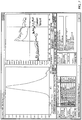
- FIG. 1 shows a laser beam instrument in accordance with one or more embodiments disclosed herein.
- the laser beam instrument includes a laser beam (102), optics (104), and a probe window (106).
- the laser beam instrument is a probe tube (100) that includes a laser beam (102).
- the laser beam (102) is generated from a solid-state laser light source (101) that provides a continuous beam of monochromatic light that is launched down the laser probe (100).
- the light source may be any light source capable of generating a laser beam.
- An intricate set of lenses i.e., optics (104)
- a precision motor (not shown) (e.g., a pneumatic or an electric motor) is used to rotate the precision optics (104) in a circular motion at a constant speed.
- the rotating optics act to split the laser beam (102) into a circle rotating with an alternating speed between 2 and 4 m/s.
- the speed is carefully monitored and controlled throughout the measurement to ensure maximum precision in the data.
- standard probes operate to provide a fixed scan speed between 1 and 4 m/s.
- the scan speed is 2 m/s for finer particles and 4 m/s for coarse particles.
- the focused beam (110) scans a circular path at the interface between the probe window (106) and the fluid flow line (108). As the scanning focused beam (110) sweeps across the face of the probe window (106), individual particles or particle structures backscatter the laser light back to the probe tube (100). Particles and droplets closest to the probe window (106) are located in the scanning focused spot and backscatter distinct pulses of reflected light. That is, the backscattered light is detected by the probe tube (100) as a pulse measured from one edge of the particle to the opposite edge of the particle.
- the pulses of backscattered light are detected by the probe (100) and translated into chord lengths based on the a calculation of the scan speed (velocity) multiplied by the pulse width (time).
- a chord length is simply defined as the straight-line distance from one edge of a particle or particle structure to another edge ( i.e., the diameter of a particle).
- Figure 2 shows a chord length calculation in accordance with one or more embodiments disclosed herein. Specifically, Figure 2 shows a high velocity scanning laser beam that scans across the diameter of each particle that reflects off the laser beam. The duration of reflection measured is a chord.
- chord length distribution shows the number of individual chords measured per second (y-axis) as a function of the chord length dimension (x-axis).
- the chord length distribution as a "fingerprint" of the particle system, provides the ability to detect and monitor changes in particle dimension and particle count in real time.
- the laser beam instrument determines the particle size distribution (PSD) of a fluid flow line with an accuracy of 1000-2000 ⁇ m.
- the laser beam instrument disclosed herein makes no assumption of particle shape. This allows the fundamental measurement to be used to directly track changes in the particle system without unnecessary complex mathematical assumptions that could introduce significant errors to the measurement.
- the laser beam instrument may be a Lasentec® FBRM® (Focused Beam Reflection Measurement) instrument, commercially available from METTLER TOLEDO (Columbus, OH).
- the probe window (106) is a sapphire window.
- the laser beam instrument (probe) described in Figure 1 is used to measure PSD of particles in a fluid line that provides a wellbore fluid to bridge/plug fractures and pores in a reservoir. More specifically, the bridging material (also known as lost circulation material (LCM)) is added to the fluid flow line and the PSD of the bridging material is calculated using the laser beam instrument described above. Bridging material is a substance added to cement slurries or drilling mud to prevent the loss of cement or mud to the formation and may be fibrous, flaky, or granular material.
- LCM lost circulation material
- Bridging materials may include, but are not limited to, Fordadol Z2, G-Seal® (provided by M-I LLC (Houston, TX)), Microdol 40/200, Calcium Carbonate M, and/or any combination thereof.
- an ideal blend of bridging materials i.e., an ideal packing theory combines 4-6 bridging products, such as those described above.
- the laser beam instrument in embodiments disclosed herein is able to provide a continuous measurement of particle sizes and changes in PSD while adding various sized products to a fluid flow line.
- the size of the particles that are added does not affect the instrument's ability to detect changes in PSD.
- the laser beam instrument is set up (in a training phase) in software before being inserted into the fluid flow line for purposes of obtaining PSD measurements.
- Table 1 shows an overview of products, planned concentrations, and particle size ranges used in the software setup for the laser beam instrument. The ranges are chosen as typical ranges for characterization of each added bridging material such that the laser beam instrument may identify changes in population of each bridging product as they are added to the fluid flow line. The particle sizes are chosen to cover both pore bridging and bridging of induced or natural fractures while drilling depleted zones in the reservoir. Table 1.
- the PSD measurements obtained by the laser beam instrument are count based rather than based on normalized values.
- the count based interpretation allows for each channel in the system to be independent of changes in other regions of the distribution.
- the measured particles may be grouped into the different ranges shown in Table 1 in the laser beam instrument software and report form. This enables offshore personnel to maintain the concentration of the different bridging materials in the rig inventory according to actual changes in particle size distribution.
- Figure 3 shows a flow chart in accordance with one or more embodiments of the present disclosure.
- software values for the concentrations and particle size groups for various LCM/bridging materials are pre-set in the laser beam instrument (ST 200).
- the scanning speed is set both in hardware and software, and determines what size range may be detected by the instrument. For example, a scanning speed of 4 m/s is applicable for sizes 2-2048 ⁇ mm.
- the laser beam instrument may be toggled between a scanning speed of 2 and 4 m/s. The scanning speed is set by the rotational speed of the optics module, which is pneumatically driven. Subsequently, the probe tube including the laser beam instrument is inserted directly into the fluid flow line (ST 202).
- the probe window of the laser beam instrument is placed directly into the particle system (the fluid flow line).
- the probe tube may also be inserted into a return line of drilling fluid, where the return line includes drilling fluid traveling upward to the surface; thus, embodiments disclosed herein are not limited to a laser beam instrument that is inserted only into a flow line.
- the probe tube is inserted into a turbulent well-mixed fluid flow line at an angle between 30 and 60 degrees.
- the laser beam instrument is inserted at a 45 degree angle into the fluid flow line.
- a measurement of the diameter or chord length of particles is obtained using the reflectance of particles passing through scanning laser beam (ST 204).
- the duration of the reflection of the particles is determined (ST 206).
- the method of measurement is based on the duration of reflection as the particles pass through the high velocity scanning laser beam.
- the duration of reflection measured provides the chord length of each particle, as discussed above.
- the measurements depend on the shape of the particles and the orientation of the particles as the measurement is actually registered.
- the high number of measurements typically 50000-200000 particles/second
- a measure of the diameter of the particles over a specific time interval e.g., 30 seconds
- This calculation is subsequently performed to obtain the count of particles in each particle size group range (ST 208).
- the particle size count for each particle size group is used to determine what blend of bridging materials to add to the fluid flow line to bridge pores and fractures in the reservoir (ST 210).
- the particle size count is also used to determine the required minimum particle concentration necessary to identify changes in PSD due to additions of particles.
- the probe instrument measures changes in particle sizes for each individual addition of particles into the drilling fluid, regardless of the size of the particles that are added to the flow line.
- PSD is used to determine the blend of particles of bridging materials that is needed to plug pores and fractures in a reservoir.
- the PSD measurements may also be used to determine the effectiveness and verify the bridging effect of a blend of bridging products that is added to the fluid flow line.
- the PSD measurements may also be used to determine how much material for preventing fractures in the reservoir is needed.
- the preventative materials can also be added to the flow line in a manner similar to the bridging materials that are used to plug existing fractures and pores.
- PSD measurements may also be used to replace measurement of NTUs (Nephelometric Turbidity Units).
- Turbidity refers to how 'cloudy' a fluid is, and an NTU is a measurement unit that measures the lack of clarity of water, which could also be affected by the particle size distribution.
- the laser beam instrument includes a fine mode and a coarse mode.
- the coarse mode allows the instrument to interpret particles with very rough edges or even agglomerates as one particle.
- the course mode is a signal filter applied to the data before turning the data into chord lengths. This is useful for the characterization of large particles in the presence of many small particles.
- Fine mode is more sensitive than coarse mode, and is used to identify small particles. In one or more embodiments, fine mode is the default mode.
- Figures 4-7 show data review screens of the laser beam instrument in accordance with embodiments of the present disclosure during various examples of circulating fluid and adding a one or more bridging material(s) to the fluid. Each figure is described in more detail below.
- Figure 4 shows a data review screen for the addition of Fordadol Z2 bridging product in accordance with one or more embodiments disclosed herein. More specifically, Figure 4 shows the data review screen while circulating and conditioning the fluid before product addition for bridging fractures and pores is added.
- the left window shows the PSD of the fluid while circulating.
- the crosshair in the right side window shows a graph of particle size distribution a short while after the addition of 10g/l Fordadol Z2 with a D50 >1000 ⁇ m.
- the laser beam instrument measures the change in particle counts between 632 and 2000 ⁇ m, which is the pre-set range in the software to identify the Fordadol Z2 product.
- the curve in the right window demonstrates that the particle count shows a steady increase after the addition of the product completes. This increase may be because some particle agglomerates are larger than the instruments maximum readable size of 2000 ⁇ m and the counts increase over time as these large agglomerates disperse.
- Figure 5 shows changes in the PSD measured by the laser beam instrument due to the addition of G-Seal® bridging product.
- the curve in the right hand window shows a sharp increase (500) in particle counts immediately after addition of 35g/l G-Seal®.
- the amount of G-Seal® added to the fluid flow line may be any amount, and that 35g/l is merely an example.
- the decreased particle count after the initial peak is due to attrition effect as the particles are reduced in size mechanically.
- the change may also be caused by aggregates that disperse over the first few circulations in the fluid flow loop before the fluid reaches a homogenous condition.
- a first curve (502) in the left hand size window describes PSD before any addition of particles from bridging materials.
- a second curve (504) shows PSD after addition of Fordadol Z2 and is close to the first curve (502) except for the increase of particles in the 1000 ⁇ m range.
- a third curve (506) describes the expected shift to the right in the size area between 200 and 700 ⁇ m following the addition of G-Seal®.
- Figure 6 shows changes in the PSD measured by the laser beam instrument due to the addition of Microdol 40/200 bridging product.
- the specified size range used to identify Microdol 40/200 that is pre-set into the laser beam instrument using software is 47-252 ⁇ m.
- the addition of Microdol 40/200 shows a similar trend as with the addition of G-Seal® described in Figure 5 .
- the smaller fraction of G-Seal® falls in line with the coarser fraction of the Microdol 40/200, and thus, is registered by the laser beam instrument in the same manner as the addition of G-Seal®.
- the higher number of counts of particles between 47 and 252 ⁇ m before the addition of Microdol 40/200 indicates that the treated field fluid that was used as a basis to obtain this data review output graph included a certain concentration of particles within this range.
- the crosshair in the right window is set at the peak immediately after addition of Microdol 40/200.
- Figure 7 shows changes in the PSD measured by the laser beam instrument due to the addition of Calcium Carbonate M bridging product. There is no evidenced in Figure 6 of an increase in counts between 2-50 ⁇ m at the cross hair in the right window. This may be due to the relatively high concentration of fine particles present in the fluid before any additions and the finer fraction of the coarser additives.
- the laser beam instrument and software associated with the laser beam instrument are set up to focus primarily on the coarser particles rather than finer particles, which accounts for the graphs shown in Figure 7 .
- Embodiments of the disclosure provide a method and apparatus for determining particle size distribution of various materials in a fluid flow line using reflectance of particles in the fluid flow line.
- the apparatus laser beam instrument
- the apparatus is inserted directly into the flow line, without having to sample the flow line, resulting in a more accurate determine of the PSD in the flow line.
- the method of the present disclosure provides an actual count of PSD, rather than normalized values of PSD.
Landscapes
- Life Sciences & Earth Sciences (AREA)
- Mining & Mineral Resources (AREA)
- Engineering & Computer Science (AREA)
- Physics & Mathematics (AREA)
- Chemical & Material Sciences (AREA)
- Geology (AREA)
- Dispersion Chemistry (AREA)
- Biochemistry (AREA)
- Geochemistry & Mineralogy (AREA)
- Fluid Mechanics (AREA)
- Environmental & Geological Engineering (AREA)
- Health & Medical Sciences (AREA)
- Analytical Chemistry (AREA)
- General Life Sciences & Earth Sciences (AREA)
- General Health & Medical Sciences (AREA)
- General Physics & Mathematics (AREA)
- Immunology (AREA)
- Pathology (AREA)
- Investigating Or Analysing Materials By Optical Means (AREA)
- Length Measuring Devices By Optical Means (AREA)
Claims (15)
- Verfahren zum Messen der Teilchengrößenverteilung in einem Fluidmaterial, umfassend:Einführen (202) eines Laserstrahlinstruments (100) direkt in eine Fluid-Fließleitung (108), wobei das Laserstrahlinstrument einen Laserstrahl (102) auf ein direkt mit der Fluid-Fließleitung gekoppeltes Fenster (106) fokussiert, wobei die Fluid-Fließleitung (108) ein Fluid umfasst, das mehrere verschieden große Teilchen aufweist;Messen (204) eines Durchmessers von wenigstens einem Teilchen in der Fluid-Fließleitung (108) durch Reflexion des wenigstens einen Teilchens, während das wenigstens eine Teilchen durch den fokussierten Laserstrahl (110) hindurchtritt;Ermitteln (206) einer Reflexionsdauer des wenigstens einen Teilchens; undErhalten (208) einer Teilchenzählung in jeder von einer voreingestellten Bereichsgruppe von Teilchengrößen, wobei die Teilchenzählung dazu verwendet wird, die Teilchengrößenverteilung im Fluid zu ermitteln, wobei das Verfahren dadurch gekennzeichnet ist, dass die Fließleitung (108) ein Brückenbildungsprodukte enthaltendes Bohrlochfluid bereitstellt, um Risse und Bohrungen in einer Lagerstätte zu überbrücken/verstopfen, und dadurch, dass das Verfahren einVoreinstellen (200) von Bereichsgruppen von Teilchengrößen für das Laserstrahlinstrument (100) umfasst, wobei die Bereichsgruppen in Software voreingestellt werden und wobei jede der voreingestellten Bereichsgruppen von Teilchengrößen eines der in die Fließleitung (108) hinzuzugebenden Brückenbildungsprodukte repräsentiert.
- Verfahren nach Anspruch 1, das ferner umfasst:
Überwachen von Veränderungen der Teilchengrößenverteilung der Fließleitung (108), um eine Mischung von Brückenbildungsprodukten zu ermitteln, das in die Fluid-Fließleitung (108) hinzugegeben werden soll, wobei die Mischung von Brückenbildungsprodukten dazu verwendet wird, eines aus einer Pore und einem Riss in einer Lagerstätte zu überbrücken. - Verfahren nach Anspruch 1, wobei das Laserstrahlinstrument (100) in die Fluid-Fließleitung (108) in einem Winkel von 45 Grad eingeführt wird.
- Verfahren nach Anspruch 1, wobei das Laserstrahlinstrument (100) dazu ausgelegt ist, die mehreren Teilchen in der Fluid-Fließleitung (108) abzutasten, und wobei die Abtastgeschwindigkeit 2 m/s beträgt.
- Verfahren nach Anspruch 1, wobei das Laserstrahlinstrument (100) einen Grobmodus und einen Feinmodus umfasst, wobei der Grobmodus zur Charakterisierung großer Teilchen und der Feinmodus zur Charakterisierung kleiner Teilchen verwendet wird.
- Verfahren nach Anspruch 1, das ferner umfasst:Einführen des Laserstrahlinstruments (100) in eine Rücklaufleitung, wobei die Rücklaufleitung Bohrfluid umfasst, das sich nach oben nach Übertage bewegt; undErmitteln einer Teilchengrößenverteilung in der Rücklaufleitung.
- Verfahren nach Anspruch 1, wobei das Laserstrahlinstrument (100) eine Optik (104) umfasst, die dazu ausgelegt ist, sich kreisförmig zu drehen, um den Laserstrahl (102) auf das Fenster (106) zu fokussieren, wobei die Optik (104) sich mit einer festen Geschwindigkeit dreht.
- Verfahren nach Anspruch 1, wobei das Fenster (106) ein Saphiroptikfenster ist.
- Vorrichtung zum Ermitteln einer Teilchengrößenverteilung, mit:einem Laserstrahlinstrument (100) mit einem Fenster (106) und einer Laserlichtquelle (101), die dazu ausgelegt ist, einen Laserstrahl (102) in das Fenster (106) zu fokussieren, wobei das Fenster (106) direkt mit einer Fluid-Fließleitung (108) mit einem mehrere darin angeordnete Teilchen aufweisenden Fluid gekoppelt ist; undeiner Optik (104), die dazu ausgelegt ist, sich kreisförmig zu drehen, um den Laserstrahl (102) auf das Fenster (106) zu fokussieren, wobei ein Durchmesser jedes der mehreren Teilchen durch Reflexion der mehreren Teilchen gemessen wird, während die mehreren Teilchen durch den fokussierten Laserstrahl (110) hindurchtreten, wobei die Vorrichtung Mittel umfasst, die den gemessenen Durchmesser jedes der mehreren Teilchen dazu verwenden, eine Teilchenzählung für jede von einer voreingestellten Bereichsgruppe von Teilchen zu ermitteln, wobei die Vorrichtung Mittel umfasst, die die Teilchenzählung jeder voreingestellten Bereichsgruppe von Teilchen dazu verwendet, die Teilchengrößenverteilung des Fluids zu ermitteln; dadurch gekennzeichnet, dass die Fluid-Fließleitung ein Brückenbildungsprodukte enthaltendes Bohrlochfluid bereitstellt, um Risse und Bohrungen in einer Lagerstätte zu überbrücken/verstopfen, und dadurch, dass Bereichsgruppen von Teilchengrößen für das Laserstrahlinstrument (100) in der Laserstrahlinstrument-Software voreingestellt werden, wobei jede der voreingestellten Bereichsgruppen von Teilchengrößen eines der in die Fließleitung (108) hinzuzugebenden Brückenbildungsprodukte repräsentiert.
- Vorrichtung nach Anspruch 9, wobei eine Reflexionsdauer jedes der mehreren Teilchen ermittelt wird, und wobei die Berechnung der Reflexionsdauer multipliziert mit dem gemessenen Durchmesser jedes der Teilchen eine durchschnittliche Zählung für jede voreingestellte Bereichsgruppe von Teilchen bereitstellt.
- Vorrichtung nach Anspruch 9, wobei die Optik (104) sich mit einer festen Geschwindigkeit dreht.
- Vorrichtung nach Anspruch 9, wobei das Laserstrahlinstrument (100) in die Fluid-Fließleitung (108) in einem Winkel von 45 Grad eingeführt wird.
- Vorrichtung nach Anspruch 9, wobei das Laserstrahlinstrument (100) dazu ausgelegt ist, die mehreren Teilchen in der Fluid-Fließleitung (108) abzutasten, und wobei die Abtastgeschwindigkeit 2 m/s beträgt.
- Vorrichtung nach Anspruch 9, wobei die Teilchengrößenverteilung im Fluid überwacht wird, um eine Mischung zu ermitteln, das in die Fluid-Fließleitung (108) hinzugegeben werden soll, wobei die Mischung von Brückenbildungsprodukten dazu verwendet wird, eines aus einer Pore und einem Riss in einer Lagerstätte zu überbrücken.
- Vorrichtung nach Anspruch 9, wobei das Fenster (106) ein Saphiroptikfenster ist.
Applications Claiming Priority (2)
| Application Number | Priority Date | Filing Date | Title |
|---|---|---|---|
| US10780108P | 2008-10-23 | 2008-10-23 | |
| PCT/US2009/061471 WO2010048276A2 (en) | 2008-10-23 | 2009-10-21 | Method and apparatus for measuring particle size distribution in drilling fluid |
Publications (3)
| Publication Number | Publication Date |
|---|---|
| EP2909604A2 EP2909604A2 (de) | 2015-08-26 |
| EP2909604A4 EP2909604A4 (de) | 2016-08-03 |
| EP2909604B1 true EP2909604B1 (de) | 2019-06-26 |
Family
ID=42119956
Family Applications (1)
| Application Number | Title | Priority Date | Filing Date |
|---|---|---|---|
| EP09822619.4A Active EP2909604B1 (de) | 2008-10-23 | 2009-10-21 | Verfahren und vorrichtung zur messung der partikelgrössenverteilung in einer bohrflüssigkeit |
Country Status (8)
| Country | Link |
|---|---|
| US (1) | US8427640B2 (de) |
| EP (1) | EP2909604B1 (de) |
| AR (1) | AR073966A1 (de) |
| BR (1) | BRPI0920623A2 (de) |
| CA (1) | CA2740587C (de) |
| EA (1) | EA021737B1 (de) |
| MX (1) | MX2011004164A (de) |
| WO (1) | WO2010048276A2 (de) |
Families Citing this family (12)
| Publication number | Priority date | Publication date | Assignee | Title |
|---|---|---|---|---|
| US9007580B2 (en) * | 2011-04-11 | 2015-04-14 | Schlumberger Norge As | Method and apparatus for measuring particle size distribution in drilling fluid |
| WO2012099234A1 (ja) | 2011-01-20 | 2012-07-26 | オリンパス株式会社 | 単一発光粒子からの光の検出を用いた光分析方法及び光分析装置 |
| EP2746748B1 (de) | 2011-08-15 | 2017-12-06 | Olympus Corporation | Fotometrische analysevorrichtung mit erkennung einzelner lichtemittierender partikel, verfahren für fotometrische analyse und computerprogramm für fotometrische analyse |
| CN103765196B (zh) | 2011-08-26 | 2016-03-02 | 奥林巴斯株式会社 | 利用单个发光粒子检测的光分析装置及光分析方法 |
| WO2013052796A1 (en) | 2011-10-07 | 2013-04-11 | Saudi Arabian Oil Company | Classification scheme of sized bridging materials for superior drill-in fluid design |
| AU2013402496B2 (en) | 2013-10-09 | 2016-10-27 | Halliburton Energy Services, Inc. | Systems and methods for measuring downhole fluid characteristics in drilling fluids |
| US8812236B1 (en) * | 2014-04-11 | 2014-08-19 | Particle Size Engineering, LLC | Method for using particle size analysis in near time or real time to create a proper particle size distribution within a drilling fluid management system for improved well drilling efficiency |
| GB2540101B (en) * | 2014-07-08 | 2020-09-09 | Halliburton Energy Services Inc | Real-time optical flow imaging to determine particle size distribution |
| US11077521B2 (en) * | 2014-10-30 | 2021-08-03 | Schlumberger Technology Corporation | Creating radial slots in a subterranean formation |
| WO2017098597A1 (ja) | 2015-12-09 | 2017-06-15 | オリンパス株式会社 | 単一発光粒子検出を用いた光分析方法及び光分析装置 |
| CN111195454A (zh) * | 2018-11-16 | 2020-05-26 | 研能科技股份有限公司 | 净化气体装置 |
| CN112781495B (zh) * | 2020-12-31 | 2022-07-12 | 合肥工业大学 | 一种基于悬浮激光结构的三维接触触发式测量探头 |
Family Cites Families (11)
| Publication number | Priority date | Publication date | Assignee | Title |
|---|---|---|---|---|
| US4728190A (en) * | 1985-10-15 | 1988-03-01 | Particle Measuring Systems, Inc. | Device and method for optically detecting particles in a fluid |
| US4871251A (en) | 1987-04-27 | 1989-10-03 | Preikschat F K | Apparatus and method for particle analysis |
| GB8726305D0 (en) * | 1987-11-10 | 1987-12-16 | Secr Defence | Portable particle analysers |
| US4917496A (en) * | 1988-07-11 | 1990-04-17 | Pacific Scientific Company | Particle size measuring instrument with direct scattered light detection |
| US5815264A (en) * | 1994-09-21 | 1998-09-29 | Laser Sensor Technology, Inc | System for acquiring an image of a multi-phase fluid by measuring backscattered light |
| GB2335269A (en) * | 1998-03-10 | 1999-09-15 | Messtechnik Schwartz Gmbh | Measuring particles in a flowing fluid |
| DE60029878T2 (de) | 1999-05-04 | 2007-03-15 | Mettler-Toledo Autochem, Inc. | Verfahren und Vorrichtung zur Bestimmung von Teilchen unter Benutzung der Reflexion eines mehrfachabtastenden Strahls |
| WO2001096868A2 (en) * | 2000-06-12 | 2001-12-20 | Sysmex Corporation | Immunoassay and immunoassay apparatus |
| US7050166B2 (en) * | 2001-11-02 | 2006-05-23 | Baker Hughes Incorporated | Calcium carbonate imaging technique |
| KR100459477B1 (ko) | 2002-04-20 | 2004-12-03 | 엘지산전 주식회사 | 부하개폐 커넥터 |
| US7456960B2 (en) * | 2005-06-06 | 2008-11-25 | Particle Measuring Systems, Inc. | Particle counter with improved image sensor array |
-
2009
- 2009-10-21 CA CA2740587A patent/CA2740587C/en not_active Expired - Fee Related
- 2009-10-21 EA EA201170599A patent/EA021737B1/ru not_active IP Right Cessation
- 2009-10-21 US US13/123,541 patent/US8427640B2/en active Active
- 2009-10-21 EP EP09822619.4A patent/EP2909604B1/de active Active
- 2009-10-21 WO PCT/US2009/061471 patent/WO2010048276A2/en not_active Ceased
- 2009-10-21 BR BRPI0920623A patent/BRPI0920623A2/pt not_active IP Right Cessation
- 2009-10-21 MX MX2011004164A patent/MX2011004164A/es active IP Right Grant
- 2009-10-23 AR ARP090104098A patent/AR073966A1/es active IP Right Grant
Non-Patent Citations (1)
| Title |
|---|
| None * |
Also Published As
| Publication number | Publication date |
|---|---|
| EA021737B1 (ru) | 2015-08-31 |
| BRPI0920623A2 (pt) | 2015-12-22 |
| WO2010048276A2 (en) | 2010-04-29 |
| US20110192595A1 (en) | 2011-08-11 |
| EP2909604A4 (de) | 2016-08-03 |
| CA2740587A1 (en) | 2010-04-29 |
| AR073966A1 (es) | 2010-12-15 |
| US8427640B2 (en) | 2013-04-23 |
| WO2010048276A3 (en) | 2010-07-29 |
| CA2740587C (en) | 2014-08-19 |
| EA201170599A1 (ru) | 2011-10-31 |
| EP2909604A2 (de) | 2015-08-26 |
| MX2011004164A (es) | 2011-06-24 |
Similar Documents
| Publication | Publication Date | Title |
|---|---|---|
| EP2909604B1 (de) | Verfahren und vorrichtung zur messung der partikelgrössenverteilung in einer bohrflüssigkeit | |
| US10228315B2 (en) | Method and apparatus for measuring particle size distribution in drilling fluid | |
| Maaß et al. | Experimental comparison of measurement techniques for drop size distributions in liquid/liquid dispersions | |
| Tadayyon et al. | Determination of Particle Size Distribution by Par‐Tec® 100: Modeling and Experimental Results | |
| CA2923008C (en) | Systems and methods for measuring downhole fluid characteristics in drilling fluids | |
| NL1041678B1 (en) | Classifying particle size and shape distribution in drilling fluids | |
| US11739479B2 (en) | Yankee dryer profiler and control | |
| US5453837A (en) | Interferometric device for determining sizes and properties of cylindrical objects based on phase shift measurements | |
| WO1997034139A1 (en) | Method and system for measuring particle geometry | |
| US5561520A (en) | Measuring properties of a slurry | |
| Kail et al. | Advanced geometrical modeling of focused beam reflectance measurements (FBRM) | |
| US8149401B2 (en) | System and method for distinguishing particles in a transient fluid | |
| Abbas et al. | Investigation of on-line optical particle characterization in reaction and cooling crystallization systems. Current state of the art | |
| CN103776802B (zh) | 测量粘弹性流体的微流变测量装置及方法 | |
| WO2010055280A1 (en) | Determining the particle size distribution of a suspension | |
| CN223289439U (zh) | 测量设备 | |
| Gupta et al. | Determination of the Size of Microspheres in Monodisperse Turbid Solutions | |
| Rheims et al. | Working Principle and Experimental Results for a Differential Phase‐Doppler Technique | |
| JP3714679B2 (ja) | 第二の流体中に細かく分離した第一の流体の濃度を判定する方法および装置 | |
| Bo¨ hm et al. | Detection of nm-scale scratches on high gloss metal sheets by a light scattering method | |
| Bernhardt | Particle Size Analysis—Problems and Possibilities in the Fine and Ultrafine Range | |
| Maaß et al. | Chair of Chemical and Process Engineering/TU Berlin, Straße des 17. Juni 135, Sekr. MA 5-7, 10623 Berlin, Germany; phone: 0049-30-314-23171 2) Department of Fluid Mechanics/Anhalt University of Applied Sciences, Germany 3) Department of Chemical Engineering/University" Otto-von-Guericke" Magdeburg, Germany* corresponding author: sebastian. maass@ tu-berlin. de | |
| Pérez-Moret et al. | Design and Construction of the automated scatterometer for particle sizing | |
| Shukla et al. | Ultrasonic Based Process Monitoring Using Advanced Data Processing and Analysis | |
| Shahi et al. | Experimental Investigation of Settling Velocity of Natural Sands in Power-Law Fluid Using Particle Image Shadowgraph |
Legal Events
| Date | Code | Title | Description |
|---|---|---|---|
| PUAI | Public reference made under article 153(3) epc to a published international application that has entered the european phase |
Free format text: ORIGINAL CODE: 0009012 |
|
| 17P | Request for examination filed |
Effective date: 20110523 |
|
| AK | Designated contracting states |
Kind code of ref document: A2 Designated state(s): AT BE BG CH CY CZ DE DK EE ES FI FR GB GR HR HU IE IS IT LI LT LU LV MC MK MT NL NO PL PT RO SE SI SK SM TR |
|
| A4 | Supplementary search report drawn up and despatched |
Effective date: 20160705 |
|
| RIC1 | Information provided on ipc code assigned before grant |
Ipc: G01B 11/10 20060101ALI20160630BHEP Ipc: E21B 43/26 20060101ALI20160630BHEP Ipc: G01N 15/02 20060101AFI20160630BHEP Ipc: E21B 33/138 20060101ALI20160630BHEP Ipc: G01N 21/85 20060101ALI20160630BHEP |
|
| STAA | Information on the status of an ep patent application or granted ep patent |
Free format text: STATUS: EXAMINATION IS IN PROGRESS |
|
| 17Q | First examination report despatched |
Effective date: 20180608 |
|
| RIC1 | Information provided on ipc code assigned before grant |
Ipc: G01B 11/10 20060101ALI20181203BHEP Ipc: G01N 21/53 20060101ALI20181203BHEP Ipc: G01N 15/02 20060101AFI20181203BHEP Ipc: E21B 33/138 20060101ALI20181203BHEP Ipc: G01N 21/85 20060101ALI20181203BHEP Ipc: E21B 43/26 20060101ALI20181203BHEP Ipc: G01N 15/14 20060101ALI20181203BHEP |
|
| GRAP | Despatch of communication of intention to grant a patent |
Free format text: ORIGINAL CODE: EPIDOSNIGR1 |
|
| STAA | Information on the status of an ep patent application or granted ep patent |
Free format text: STATUS: GRANT OF PATENT IS INTENDED |
|
| INTG | Intention to grant announced |
Effective date: 20190115 |
|
| RAP1 | Party data changed (applicant data changed or rights of an application transferred) |
Owner name: M-I L.L.C. Owner name: SCHLUMBERGER NORGE AS |
|
| GRAS | Grant fee paid |
Free format text: ORIGINAL CODE: EPIDOSNIGR3 |
|
| GRAA | (expected) grant |
Free format text: ORIGINAL CODE: 0009210 |
|
| STAA | Information on the status of an ep patent application or granted ep patent |
Free format text: STATUS: THE PATENT HAS BEEN GRANTED |
|
| AK | Designated contracting states |
Kind code of ref document: B1 Designated state(s): AT BE BG CH CY CZ DE DK EE ES FI FR GB GR HR HU IE IS IT LI LT LU LV MC MK MT NL NO PL PT RO SE SI SK SM TR |
|
| REG | Reference to a national code |
Ref country code: GB Ref legal event code: FG4D |
|
| REG | Reference to a national code |
Ref country code: CH Ref legal event code: EP |
|
| REG | Reference to a national code |
Ref country code: AT Ref legal event code: REF Ref document number: 1148858 Country of ref document: AT Kind code of ref document: T Effective date: 20190715 |
|
| REG | Reference to a national code |
Ref country code: DE Ref legal event code: R096 Ref document number: 602009058924 Country of ref document: DE |
|
| REG | Reference to a national code |
Ref country code: IE Ref legal event code: FG4D |
|
| REG | Reference to a national code |
Ref country code: NL Ref legal event code: MP Effective date: 20190626 |
|
| PG25 | Lapsed in a contracting state [announced via postgrant information from national office to epo] |
Ref country code: HR Free format text: LAPSE BECAUSE OF FAILURE TO SUBMIT A TRANSLATION OF THE DESCRIPTION OR TO PAY THE FEE WITHIN THE PRESCRIBED TIME-LIMIT Effective date: 20190626 Ref country code: LT Free format text: LAPSE BECAUSE OF FAILURE TO SUBMIT A TRANSLATION OF THE DESCRIPTION OR TO PAY THE FEE WITHIN THE PRESCRIBED TIME-LIMIT Effective date: 20190626 Ref country code: FI Free format text: LAPSE BECAUSE OF FAILURE TO SUBMIT A TRANSLATION OF THE DESCRIPTION OR TO PAY THE FEE WITHIN THE PRESCRIBED TIME-LIMIT Effective date: 20190626 Ref country code: SE Free format text: LAPSE BECAUSE OF FAILURE TO SUBMIT A TRANSLATION OF THE DESCRIPTION OR TO PAY THE FEE WITHIN THE PRESCRIBED TIME-LIMIT Effective date: 20190626 |
|
| REG | Reference to a national code |
Ref country code: LT Ref legal event code: MG4D |
|
| REG | Reference to a national code |
Ref country code: NO Ref legal event code: T2 Effective date: 20190626 |
|
| PG25 | Lapsed in a contracting state [announced via postgrant information from national office to epo] |
Ref country code: BG Free format text: LAPSE BECAUSE OF FAILURE TO SUBMIT A TRANSLATION OF THE DESCRIPTION OR TO PAY THE FEE WITHIN THE PRESCRIBED TIME-LIMIT Effective date: 20190926 Ref country code: GR Free format text: LAPSE BECAUSE OF FAILURE TO SUBMIT A TRANSLATION OF THE DESCRIPTION OR TO PAY THE FEE WITHIN THE PRESCRIBED TIME-LIMIT Effective date: 20190927 Ref country code: LV Free format text: LAPSE BECAUSE OF FAILURE TO SUBMIT A TRANSLATION OF THE DESCRIPTION OR TO PAY THE FEE WITHIN THE PRESCRIBED TIME-LIMIT Effective date: 20190626 |
|
| REG | Reference to a national code |
Ref country code: AT Ref legal event code: MK05 Ref document number: 1148858 Country of ref document: AT Kind code of ref document: T Effective date: 20190626 |
|
| PG25 | Lapsed in a contracting state [announced via postgrant information from national office to epo] |
Ref country code: EE Free format text: LAPSE BECAUSE OF FAILURE TO SUBMIT A TRANSLATION OF THE DESCRIPTION OR TO PAY THE FEE WITHIN THE PRESCRIBED TIME-LIMIT Effective date: 20190626 Ref country code: NL Free format text: LAPSE BECAUSE OF FAILURE TO SUBMIT A TRANSLATION OF THE DESCRIPTION OR TO PAY THE FEE WITHIN THE PRESCRIBED TIME-LIMIT Effective date: 20190626 Ref country code: SK Free format text: LAPSE BECAUSE OF FAILURE TO SUBMIT A TRANSLATION OF THE DESCRIPTION OR TO PAY THE FEE WITHIN THE PRESCRIBED TIME-LIMIT Effective date: 20190626 Ref country code: PT Free format text: LAPSE BECAUSE OF FAILURE TO SUBMIT A TRANSLATION OF THE DESCRIPTION OR TO PAY THE FEE WITHIN THE PRESCRIBED TIME-LIMIT Effective date: 20191028 Ref country code: CZ Free format text: LAPSE BECAUSE OF FAILURE TO SUBMIT A TRANSLATION OF THE DESCRIPTION OR TO PAY THE FEE WITHIN THE PRESCRIBED TIME-LIMIT Effective date: 20190626 Ref country code: RO Free format text: LAPSE BECAUSE OF FAILURE TO SUBMIT A TRANSLATION OF THE DESCRIPTION OR TO PAY THE FEE WITHIN THE PRESCRIBED TIME-LIMIT Effective date: 20190626 Ref country code: AT Free format text: LAPSE BECAUSE OF FAILURE TO SUBMIT A TRANSLATION OF THE DESCRIPTION OR TO PAY THE FEE WITHIN THE PRESCRIBED TIME-LIMIT Effective date: 20190626 |
|
| PG25 | Lapsed in a contracting state [announced via postgrant information from national office to epo] |
Ref country code: SM Free format text: LAPSE BECAUSE OF FAILURE TO SUBMIT A TRANSLATION OF THE DESCRIPTION OR TO PAY THE FEE WITHIN THE PRESCRIBED TIME-LIMIT Effective date: 20190626 Ref country code: IS Free format text: LAPSE BECAUSE OF FAILURE TO SUBMIT A TRANSLATION OF THE DESCRIPTION OR TO PAY THE FEE WITHIN THE PRESCRIBED TIME-LIMIT Effective date: 20191026 Ref country code: ES Free format text: LAPSE BECAUSE OF FAILURE TO SUBMIT A TRANSLATION OF THE DESCRIPTION OR TO PAY THE FEE WITHIN THE PRESCRIBED TIME-LIMIT Effective date: 20190626 |
|
| PG25 | Lapsed in a contracting state [announced via postgrant information from national office to epo] |
Ref country code: TR Free format text: LAPSE BECAUSE OF FAILURE TO SUBMIT A TRANSLATION OF THE DESCRIPTION OR TO PAY THE FEE WITHIN THE PRESCRIBED TIME-LIMIT Effective date: 20190626 |
|
| PG25 | Lapsed in a contracting state [announced via postgrant information from national office to epo] |
Ref country code: DK Free format text: LAPSE BECAUSE OF FAILURE TO SUBMIT A TRANSLATION OF THE DESCRIPTION OR TO PAY THE FEE WITHIN THE PRESCRIBED TIME-LIMIT Effective date: 20190626 Ref country code: PL Free format text: LAPSE BECAUSE OF FAILURE TO SUBMIT A TRANSLATION OF THE DESCRIPTION OR TO PAY THE FEE WITHIN THE PRESCRIBED TIME-LIMIT Effective date: 20190626 |
|
| PG25 | Lapsed in a contracting state [announced via postgrant information from national office to epo] |
Ref country code: MC Free format text: LAPSE BECAUSE OF FAILURE TO SUBMIT A TRANSLATION OF THE DESCRIPTION OR TO PAY THE FEE WITHIN THE PRESCRIBED TIME-LIMIT Effective date: 20190626 Ref country code: IS Free format text: LAPSE BECAUSE OF FAILURE TO SUBMIT A TRANSLATION OF THE DESCRIPTION OR TO PAY THE FEE WITHIN THE PRESCRIBED TIME-LIMIT Effective date: 20200224 |
|
| REG | Reference to a national code |
Ref country code: CH Ref legal event code: PL |
|
| REG | Reference to a national code |
Ref country code: DE Ref legal event code: R097 Ref document number: 602009058924 Country of ref document: DE |
|
| PLBE | No opposition filed within time limit |
Free format text: ORIGINAL CODE: 0009261 |
|
| STAA | Information on the status of an ep patent application or granted ep patent |
Free format text: STATUS: NO OPPOSITION FILED WITHIN TIME LIMIT |
|
| PG2D | Information on lapse in contracting state deleted |
Ref country code: IS |
|
| PG25 | Lapsed in a contracting state [announced via postgrant information from national office to epo] |
Ref country code: LI Free format text: LAPSE BECAUSE OF NON-PAYMENT OF DUE FEES Effective date: 20191031 Ref country code: CH Free format text: LAPSE BECAUSE OF NON-PAYMENT OF DUE FEES Effective date: 20191031 Ref country code: LU Free format text: LAPSE BECAUSE OF NON-PAYMENT OF DUE FEES Effective date: 20191021 |
|
| 26N | No opposition filed |
Effective date: 20200603 |
|
| REG | Reference to a national code |
Ref country code: BE Ref legal event code: MM Effective date: 20191031 |
|
| PG25 | Lapsed in a contracting state [announced via postgrant information from national office to epo] |
Ref country code: SI Free format text: LAPSE BECAUSE OF FAILURE TO SUBMIT A TRANSLATION OF THE DESCRIPTION OR TO PAY THE FEE WITHIN THE PRESCRIBED TIME-LIMIT Effective date: 20190626 Ref country code: BE Free format text: LAPSE BECAUSE OF NON-PAYMENT OF DUE FEES Effective date: 20191031 |
|
| PG25 | Lapsed in a contracting state [announced via postgrant information from national office to epo] |
Ref country code: IE Free format text: LAPSE BECAUSE OF NON-PAYMENT OF DUE FEES Effective date: 20191021 |
|
| PGFP | Annual fee paid to national office [announced via postgrant information from national office to epo] |
Ref country code: FR Payment date: 20200914 Year of fee payment: 12 |
|
| PGFP | Annual fee paid to national office [announced via postgrant information from national office to epo] |
Ref country code: DE Payment date: 20201006 Year of fee payment: 12 Ref country code: IT Payment date: 20200911 Year of fee payment: 12 |
|
| PG25 | Lapsed in a contracting state [announced via postgrant information from national office to epo] |
Ref country code: CY Free format text: LAPSE BECAUSE OF FAILURE TO SUBMIT A TRANSLATION OF THE DESCRIPTION OR TO PAY THE FEE WITHIN THE PRESCRIBED TIME-LIMIT Effective date: 20190626 |
|
| PG25 | Lapsed in a contracting state [announced via postgrant information from national office to epo] |
Ref country code: MT Free format text: LAPSE BECAUSE OF FAILURE TO SUBMIT A TRANSLATION OF THE DESCRIPTION OR TO PAY THE FEE WITHIN THE PRESCRIBED TIME-LIMIT Effective date: 20190626 Ref country code: HU Free format text: LAPSE BECAUSE OF FAILURE TO SUBMIT A TRANSLATION OF THE DESCRIPTION OR TO PAY THE FEE WITHIN THE PRESCRIBED TIME-LIMIT; INVALID AB INITIO Effective date: 20091021 |
|
| REG | Reference to a national code |
Ref country code: DE Ref legal event code: R119 Ref document number: 602009058924 Country of ref document: DE |
|
| PG25 | Lapsed in a contracting state [announced via postgrant information from national office to epo] |
Ref country code: MK Free format text: LAPSE BECAUSE OF FAILURE TO SUBMIT A TRANSLATION OF THE DESCRIPTION OR TO PAY THE FEE WITHIN THE PRESCRIBED TIME-LIMIT Effective date: 20190626 |
|
| PG25 | Lapsed in a contracting state [announced via postgrant information from national office to epo] |
Ref country code: DE Free format text: LAPSE BECAUSE OF NON-PAYMENT OF DUE FEES Effective date: 20220503 |
|
| PG25 | Lapsed in a contracting state [announced via postgrant information from national office to epo] |
Ref country code: FR Free format text: LAPSE BECAUSE OF NON-PAYMENT OF DUE FEES Effective date: 20211031 |
|
| PG25 | Lapsed in a contracting state [announced via postgrant information from national office to epo] |
Ref country code: IT Free format text: LAPSE BECAUSE OF NON-PAYMENT OF DUE FEES Effective date: 20211021 |
|
| PGFP | Annual fee paid to national office [announced via postgrant information from national office to epo] |
Ref country code: GB Payment date: 20230831 Year of fee payment: 15 |
|
| GBPC | Gb: european patent ceased through non-payment of renewal fee |
Effective date: 20241021 |
|
| PG25 | Lapsed in a contracting state [announced via postgrant information from national office to epo] |
Ref country code: GB Free format text: LAPSE BECAUSE OF NON-PAYMENT OF DUE FEES Effective date: 20241021 |
|
| PGFP | Annual fee paid to national office [announced via postgrant information from national office to epo] |
Ref country code: NO Payment date: 20251009 Year of fee payment: 17 |