EP2909959B1 - Procédés et dispositif concentrateur de périphérie de services dans un noeud de réseau optique - Google Patents
Procédés et dispositif concentrateur de périphérie de services dans un noeud de réseau optique Download PDFInfo
- Publication number
- EP2909959B1 EP2909959B1 EP13706318.6A EP13706318A EP2909959B1 EP 2909959 B1 EP2909959 B1 EP 2909959B1 EP 13706318 A EP13706318 A EP 13706318A EP 2909959 B1 EP2909959 B1 EP 2909959B1
- Authority
- EP
- European Patent Office
- Prior art keywords
- optical
- wavelength
- ports
- service
- hub device
- Prior art date
- Legal status (The legal status is an assumption and is not a legal conclusion. Google has not performed a legal analysis and makes no representation as to the accuracy of the status listed.)
- Active
Links
Images




Classifications
-
- H—ELECTRICITY
- H04—ELECTRIC COMMUNICATION TECHNIQUE
- H04J—MULTIPLEX COMMUNICATION
- H04J14/00—Optical multiplex systems
- H04J14/02—Wavelength-division multiplex systems
- H04J14/0201—Add-and-drop multiplexing
- H04J14/0202—Arrangements therefor
- H04J14/0204—Broadcast and select arrangements, e.g. with an optical splitter at the input before adding or dropping
-
- H—ELECTRICITY
- H04—ELECTRIC COMMUNICATION TECHNIQUE
- H04J—MULTIPLEX COMMUNICATION
- H04J14/00—Optical multiplex systems
- H04J14/02—Wavelength-division multiplex systems
- H04J14/0201—Add-and-drop multiplexing
- H04J14/0202—Arrangements therefor
- H04J14/0205—Select and combine arrangements, e.g. with an optical combiner at the output after adding or dropping
-
- H—ELECTRICITY
- H04—ELECTRIC COMMUNICATION TECHNIQUE
- H04J—MULTIPLEX COMMUNICATION
- H04J14/00—Optical multiplex systems
- H04J14/02—Wavelength-division multiplex systems
- H04J14/0201—Add-and-drop multiplexing
- H04J14/0202—Arrangements therefor
- H04J14/021—Reconfigurable arrangements, e.g. reconfigurable optical add/drop multiplexers [ROADM] or tunable optical add/drop multiplexers [TOADM]
- H04J14/0212—Reconfigurable arrangements, e.g. reconfigurable optical add/drop multiplexers [ROADM] or tunable optical add/drop multiplexers [TOADM] using optical switches or wavelength selective switches [WSS]
Definitions
- the present invention relates to a node of an optical network, methods and service edge hub devices attachable to an optical network.
- Hub nodes are essential nodes in optical networks carrying data traffic comprising data information on a number of optical wavelength channels in optical fibres.
- the hub node connects uplink traffic from one or more network nodes to a higher-tiered network.
- the edge node then performs subscriber management and routes the uplink traffic, typically at the packet level, towards an appropriate destination, such as to content services, back towards the access networks, to the Internet, etc.
- Such edge node routing may entail sending the uplink traffic to a regional network, which operates back at the optical layer.
- a hub node connects to multiple edge nodes and the edge nodes in turn connect to the regional network.
- transport convergence is essential, i.e. such transport network should be capable of transporting any type of service.
- Such services include mobile backhaul, either traditional Ethernet/packet based or main-remote based with, e.g. Common Public Radio Interface (CPRI), business services, and residential services.
- CPRI Common Public Radio Interface
- Some networks comprises in accordance with their defined functionality and configuration two transport interfaces: one at the access location and one at the service edge.
- the service edge location can also be called a Hub to put emphasis on the typically more or less hubbed traffic profile or access/aggregation networks.
- the different services may be represented by different equipments/physical ports.
- a hub arrangement comprises at least one Wavelength Selective Switch, WSS, for directing the wavelength channels and the data packets carried by the wavelength channels to different services, and for directing wavelength channels from the service equipment to a Central Office (CO) node.
- WSS Wavelength Selective Switch
- the WSS is connected to one or more COs.
- US 2008/0317466A1 describes a multi-ring network operating method of cross-connecting an input working ring and an input protection ring of a first ring network to an output working ring and an output protection ring of a second ring network.
- " STEVE"N GRINGERI ET AL 'Flexible architectures for optical transport nodes and networks', IEEE COMMUNICATIONS MAGAZINE, IEEE SERVICE CENTER, PISCATAWAY, US, vol. 48, no. 7, 1 July 2010 (2010-07-01), pages 40-50, XP011312222, ISSN: 0163-6804 " describes an arrayed waveguide that separates a group of wavelengths into individual wavelengths, using a wavelength splitter.
- TURKCU 0 ET AL 'Performance of Optical Networks With Limited Reconfigurability', IEEE / ACM TRANSACTIONS ON NETWORKING, IEEE / ACM, NEW YORK, NY, US, vol. 17, no. 6, 1 December 2009 (2009-12-01), pages 2002-2013, XP011282637, ISSN: 1063-6692, DOI: 10.1109/TNET.2009.2014158 " describes a reconfigurable optical add/drop multiplexer (ROADM) using a broadcast-and-select architecture and comprising a drop module, an add module and a wavelength blocker.
- ROADM reconfigurable optical add/drop multiplexer
- Embodiments herein advantageously solve said above described problems by offering a flexible optical layer.
- examples of embodiments of a service edge hub device attachable to an optical network carrying data traffic comprising data information on optical wavelength channels are provided.
- Said service edge hub device comprises a plurality of optical ports connectable to one or more service equipment arrangements for digital processing the data information.
- the service edge hub device further comprises a wavelength switching means configured to connect each individual optical wavelength channel to a different port of the plurality of optical ports, wherein the wavelength switching means comprises an optical splitter arrangement, wherein the optical splitter arrangement comprises one or more N:N optical splitters for individually spreading and directing each individual optical wavelength channel to the different port of the plurality of optical ports connectable to the one or more service equipment arrangements in one direction, and one or more network ports, in the other direction, and wherein the one or more N:N optical splitters are controlled by controllable optical filters.
- the wavelength switching means comprises an optical splitter arrangement, wherein the optical splitter arrangement comprises one or more N:N optical splitters for individually spreading and directing each individual optical wavelength channel to the different port of the plurality of optical ports connectable to the one or more service equipment arrangements in one direction, and one or more network ports, in the other direction, and wherein the one or more N:N optical splitters are controlled by controllable optical filters.
- inventions of a node in an optical communications network are provided.
- Said node embodiments may comprise any of the service edge hub device embodiments provided herein.
- examples of embodiments of methods in a service edge hub device attachable to an optical network carrying data traffic comprising data information on optical wavelength channels are provided.
- Said service edge hub device comprises a plurality of optical ports connected to one or more service equipment arrangements for digital processing the data information.
- the hub device comprises a wavelength switching means configured to connect each individual optical wavelength channel to a different port of the plurality of optical ports connected to the one or more service equipment arrangements.
- Said method involves individually spreading and directing each individual optical wavelength channel to the different port of the plurality of optical ports connected to the one or more service equipment arrangements by means of the wavelength switching means comprising an optical splitter arrangement, wherein the optical splitter arrangement comprises one or more N:N optical splitters, in one direction, and one or more network ports connected to the optical network, in the other direction, and wherein the one or more N:N optical splitters are controlled by controllable optical filters.
- the present invention relates to a node of an optical network, methods and service edge hub devices attachable to an optical network.
- a generic tiered architecture for optical transport networks configured to transport wavelength division multiplexed, WDM, traffic is discussed.
- MetNet is here defined as a DWDM-centric access/aggregation/metro optical transport solution for converged networks.
- the network nodes use wavelength layer switches, i.e. active WSSes. Total transmission distances are likely below 100 km and bitrates up to 10 Gbps in contrast with metro/regional networks.
- Bidirectional fiber transmission, narrow wavelength spacing (eg 25 GHz) and wide optical bands (e.g. C+L) are in the functional scope to be used when cost-efficient unless transmission prohibited.
- optical wavelength channel e.g. wavelength, channel, wavelength channel, carrier, optical carrier, optical channel, optical channel, wavelength carrier, etc.
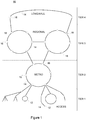
- Figure 1 illustrates a generic tiered architecture 10 for optical transport networks configured to transport wavelength division multiplexed, WDM, traffic.
- the networks comprise optical fibres for carrying the optical traffic between the nodes of said networks.
- Access networks may also use wireless and copper wire for communication of signalling and payload traffic.
- Each wavelength constitutes a channel or optical carrier for carrying information, for example in data packets, according to any suitable protocol, e.g. Internet protocol.
- Each channel A uses a frequency band having a certain bandwidth wherein the wavelength Ai is the centre frequency of the frequency band.
- wavelength-division multiplexing WDM
- WDM wavelength-division multiplexing
- WDM is a technology which multiplexes a number of optical carrier signals onto a single optical fibre by using different wavelengths (i.e. colours) of laser light. This technique enables uni- or bi-directional communications over one strand of fibre, as well as multiplication of capacity.
- Said optical carriers or channels, i.e. wavelengths are separated according to WDM systems, which are divided into different wavelength plans, coarse, CWDM, and dense, DWDM.
- Dense WDM systems provide up to 40 channels at 100 GHz spacing or 80 channels with 50 GHz spacing in the 3rd transmission window, C-Band, of silica fibres around 1550 nm. Some technologies are capable of 12.5 GHz spacing or less (sometimes called ultra dense WDM).
- the lowest tier shown, tier 1 includes a plurality of access networks that are each formed from a plurality of access nodes 12 interconnected via optical fibre 14 in a ring structure, a tree structure, star structure, bus structure, a mesh structure, or any combination thereof.
- each access network aggregates uplink WDM traffic/services from the network and places the aggregated traffic onto a higher-tiered network; namely, a metro network at tier 2.
- the metro network is formed from a plurality of interconnected peer network nodes 16, also referred to as Central Offices, COs, and transports WDM traffic for the plurality of access networks.
- each peer network node aggregates WDM traffic from one or more access networks to which it is connected and transports that aggregated traffic to a hub node 18 in the metro network.
- the hub node 18 connects uplink traffic from one or more network nodes 16 to a higher-tiered network called the regional network. More specifically, the hub node 18 routes uplink traffic to an appropriate one of multiple edge nodes (not shown), e.g. a business services edge router, a residential services or a mobile services broadband network gateway, BNG, a broadband remote access server, BRAS, etc.
- the edge node then performs subscriber management and routes the uplink traffic, typically at the packet level, towards an appropriate destination, such as to content services, back towards the access networks, to the Internet, etc.
- Such edge node routing may entail sending the uplink traffic to the regional network, which operates back at the optical layer.
- the hub node 18 connects to multiple edge nodes and the edge nodes in turn connect to the regional network.
- the regional network is also formed from a plurality of interconnected peer networks nodes 16, which hub WDM traffic to a hub node 18 in the regional network much the same as in the metro network. Traffic from the regional network is then placed onto a long haul network at tier 4, for inter-regional transport. Downlink traffic propagates through the networks in an analogous, but opposite, manner.
- Each peer network node 16 typically includes a reconfigurable optical add/drop multiplexers, ROADM, that enables any WDM traffic to be selectively added or dropped from the node 16. Equipped with such hardware, a peer network node 16 can immediately drop any uplink traffic that is received from another peer network node 16 if that traffic is destined for a connected lower-tiered network.
- ROADM reconfigurable optical add/drop multiplexers
- WSSs Wavelength Selective Switches
- Embodiments herein advantageously reduce the complexity and accompanying cost of hub nodes 18. With reduced complexity and cost, the embodiments prove useful in a wider range of applications, such as optically converging the traffic of multiple services. In fact, some embodiments exploit the increased traffic resulting from such convergence in order to eliminate or at least mitigate the complexity that known networks incur for flexibility in traffic routing.
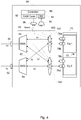
- FIG. 2 illustrates an example of an embodiment of a service edge hub device configuration according to the invention.
- Said hub device configuration 50 comprises a wavelength switching means 60, which are connected directly or indirectly to one or more ports 52.
- Said ports are bi-directional, i.e. each port is an input and output port, connecting an optical fibre from another node, preferably a Central Office, CO, node (not shown), either of the same network or another network in the same tier or another tier.
- Each wavelength constitutes a channel or carrier for carrying information, preferably in data packets, according to any suitable protocol, e.g.
- Each channel A uses a frequency band having a certain bandwidth which is multiplexed together with a number of other optical carrier signals onto the single optical fibre by using different wavelengths, i.e. colours, of laser light according to wavelength-division multiplexing, WDM, technology.
- a wavelength switching means 60 may be equipped with one or more Wavelength Selective Switches, WSSs, 80, which also comprise bidirectional in- and output terminals for directing the received wavelengths A, i.e. channels A, towards an Optical Splitter arrangement 100 comprising one or more Optical Splitters 102, 104.
- WSSs Wavelength Selective Switches
- the optical splitter arrangement 100 comprises two optical splitters indicated S1 102, and S2 104.
- the optical splitter arrangement 100 is configured to individually direct the wavelengths A, i.e. channels A, towards one or more ports of a service equipment arrangement 70.
- a WSS as used herein is configured to selectively switch or otherwise route each wavelength received at its common port to any one of its dedicated ports, independently of how other wavelengths are routed, and to aggregate wavelengths received at its dedicated ports for output from the common port.
- the service edge functions physically reside at the node 18 and within the hub node device 50, i.e. at the same location as the Hub WSSes.
- said service edge functions physically reside outside the service edge hub device 50 but are connected to the hub device 50 via ports
- the service edge functions physically reside outside the hub device 50 and the node 18 but are connected to the hub device 50 via ports.
- Said service equipment arrangement 70 may comprise one or more service equipment means for providing different services, e.g. mobile broadband backhaul, business services and residential services. Each of said ports may be dedicated to a certain one of said service equipment means 70.
- Said optical transceiver modules may be Single-Channel Optical modules (OMs) and/or Multi-Channel Optical Module (MC-OMs) 78.
- Said optical transceiver modules 78 are configured, fixed or tunable, to receive and transmit optical traffic on different wavelengths A, i.e. channels ⁇ .
- Multi-Channel Optical Module (MC-OMs) are used as optical transceiver modules 78 throughout the description, not as a limitation but more of simplicity reasons.
- Single-Channel Optical modules (OMs) may also be used as modules 78.
- An optical transceiver module like a MC-OM, is a transceiver that transforms, or converts, signals between the optical domain and the electrical domain.
- a received optical signal is transformed to an electrical signal that is possible to process by processing means, e.g. a computer, digital processor, etc.
- processing means e.g. a computer, digital processor, etc.
- the optical signal carries data packets, the content in the headers and payload of said packets could be analysed and processed by the processing means in said service equipment means after the transforming to electrical signals.
- the processed data information is meant to be sent back over the optical network, it is converted by the MC-OM 78 to the optical domain and sent on a predetermined channel having a certain wavelength ⁇ .
- a Multi-Channel Optical Module 78 is in this way capable of handling a number of channels, e,g, ⁇ 1 - ⁇ 20 . Further one or more MC-OMs 78 may be plugged into the service equipment means to facilitate reception and transmitting of other wavelength bands comprising other wavelengths and number of wavelengths. Said further MC-OMs 78 are tuned to said other wavelength bands, e.g. ⁇ 21 - ⁇ 30 , ⁇ 31 - ⁇ 60 , etc.
- the illustrated embodiment of a hub device 50 in figure 2 further comprises a hub controller 90 for controlling the operation and function of the hub device. It may be configured to control and direct the wavelengths ⁇ , i.e. channels ⁇ , via the optical splitter arrangement 100 to the correct MC-OMs, 78, of the service equipment arrangement 70 for optical traffic requesting a certain service via communication of control signalling carried in control channels ⁇ oam.
- a hub controller 90 for controlling the operation and function of the hub device. It may be configured to control and direct the wavelengths ⁇ , i.e. channels ⁇ , via the optical splitter arrangement 100 to the correct MC-OMs, 78, of the service equipment arrangement 70 for optical traffic requesting a certain service via communication of control signalling carried in control channels ⁇ oam.
- Data traffic is received over the fibres, which connect the hub with other Central Office CO nodes, preferably one node per fibre.
- data traffic will be sent from a CO on an optical fibre, e.g. 14a, according to wavelength-division multiplexing, WDM, which multiplexes a number of optical carrier signals onto a single optical fibre by using different wavelengths of laser light.
- WDM wavelength-division multiplexing
- Each wavelength constitutes a channel or carrier for carrying information, preferably in data packets, according to any suitable protocol, e.g.
- the data traffic is sent on optical wavelength channels ⁇ x in a wavelength band involving channels ⁇ 1 - ⁇ 20 from one CO, denoted CO X, to the hub 50.
- the fibre 14a is attached to one of the hub ports 52.
- the channels are directly or indirectly guided from the port 52 to a wavelength switching means 60.
- wavelength switching means 60 is equipped with two Wavelength Selective Switches, WSSs, 80 and two optical splitters, or optical beam splitters, indicated S1 102, and S2 104.
- the WSSs 80 also comprise bidirectional in- and output terminals for directing the received wavelengths ⁇ x, i.e. channels ⁇ x, towards the two Optical Splitters 102, 104, which is configured to individually spread and direct the wavelengths ⁇ , i.e. channels ⁇ , towards one or more ports 78a-d of a service equipment arrangement 70.
- Said service equipment arrangement 70 comprises service equipment means 72, 74 for providing different services, e.g. mobile broadband, business services and residential services.
- Two of said ports 78a, 78b are dedicated to a service equipment means 72, and two of said ports 78c, 78d are dedicated to a service equipment means 74.
- data traffic may be sent from another CO, denoted CO Y, on an optical fibre, e.g. 14b, according to wavelength-division multiplexing, WDM.
- Data traffic is sent on a wavelength band involving channels Ay, e.g. ⁇ 21 - ⁇ 40 , from said second CO to the hub device 50.
- a port 52 is connected to a corresponding WSS 80.
- a WSS 80 will be handling the data traffic on said fibre and direct said channels towards the WSS 80.
- the WSS 80 will direct the channels towards the optical splitter arrangement 100.
- the optical splitter arrangement 100 is configured by means of the hub controller 90 to control and direct the wavelengths Ay, i.e. channels Ay, from the optical splitter arrangement 100 to the correct MC-OMs, 78, of the service equipment arrangement 70 for optical traffic requesting a certain service.
- the hub controller may be configured to control the optical splitters 102, 104, e.g.
- MC-OMs, 78 are plugged into the ports. Said MC-OMs 78 are configured to receive and transmit optical traffic on different wavelengths A, i.e. channels ⁇ of the received wavelength channels ⁇ x and ⁇ y.
- one MC-OM, indicated 1, and plugged into port 78a of the dedicated service arrangement means 72 may be tuned to one or more of channels ⁇ 1 - ⁇ 20
- the other MC-OM, indicated 2, and plugged into port 78b may be tuned to one or more of channels ⁇ 21 - ⁇ 40
- one MC-OM, indicated 1, and plugged into port 78c may be tuned to one or more of channels ⁇ 1 - ⁇ 10
- the other MC-OM, indicated 2, and plugged into port 78d may be tuned to one or more of channels ⁇ 11 - ⁇ 40 .
- Said tuning and control of the optical transceiver modules is provided by means of the hub controller 90, an Operation Administration and Maintenance connectivity software module, OAM Conn, and OAM communication to the MC-OMs comprising an Operation, Administration and Maintenance OAM unit 224, which typically is a digital processor, microprocessor, etc.
- the received wavelength channels ⁇ x and ⁇ y together comprises channels ⁇ 1 - ⁇ 40
- each of the MC-OMs may receive any of said channels and be tuned to one or more of channels ⁇ 1 - ⁇ 40 .
- the flexibility is provided by the configuration and position of the optical splitters between the WSSs and the ports of the service equipment means 72, 74 in addition with the flexible control of the optical transceiver modules 78.
- the dedicated service arrangement means 72, 74 of the service equipment arrangement 70 is configured to digitally process the received data information. After the content of a data packet of a certain channel has been processed, said processed data packets are resent by means of Multi-Channel Optical Module, MC-OMs, 78.
- the optical splitter arrangement 100 receives the processed data packets on the channels ⁇ 1 - ⁇ 40 .
- the optical splitter arrangement 100 may be configured by means of the hub controller 90 to control and direct the wavelengths channels ⁇ , from the optical splitter arrangement 100 to the correct WSS 80 for further distribution the correct port 52 and fibre 14.
- Connection 82 enables direct wavelength layer connection between COs connected to the upper 52 and lower 52 (cf fig 4 ) without the traffic needing to go through Equipments 72, 74.
- the WSSs 80 could be redundant to each other.
- optical fibre 14a is single-homed connection between a CO node and the hub.
- the lower WSS 80 may be configured to become redundant to the top WSS 80.
- the lower WSS 80 provides resilience when the connection 14a is broken to said CO node if the port 52 of the lower WSS has been connected via the optical fibre 14b to the CO node.
- Such a configuration enables short service interruptions in case upgrades are needed, such as in-service upgrade capability e.g. by increasing bandwidth from 1Gbps per channel to 10 Gbps per channel.
- a second embodiment is exemplified in figure 3 .
- the second embodiment is in most details similar to the first embodiment described above with reference to figure 2 .
- the two embodiments differ in that the hub controller 90 of the second embodiment is further provided with an Operation Administration and Maintenance connectivity software module, OAM Conn, 92 for handling, monitoring and controlling the Multi-Channel Optical Module, MC-OMs, 78.
- Said OAM Conn 92 is further provided with a port or interface 96 for controlling the operation and function of the MC-OMs 78 by means of control signalling.
- Another benefit of the proposed embodiment is enabling point-to-multipoint (p2mp) physical (out-of-band) OAM communication ⁇ oam to the MC-OMs, indicated by dash-dot-dot lines in figure 3 .
- This is especially beneficial in the case the hub equipments are not managed by the same operator managing the optical network so that the MC-OMs cannot be managed from the electrical domain. In other words, a clear hub side demarcation for the MC-OMs is needed.
- a p2pm mechanism like GPON, or EPON, is beneficial since only one hub controller OAM connectivity port 96 is needed, i.e. GPON OLT transceiver and MAC chip.
- the MC-OMs would then need to have an internal optical filter to filter out the OAM wavelength ⁇ oam in addition to a GPON ONU (Optical Network Unit) transceiver and MAC chip.
- An implementation of a MC-OM is described in figure 6 .
- the hub controller 90 is provided with a centralized Discovery Unit, DiU, 94 for enabling the possibility to discover new hub side ports.
- the Discovery Unit may be implemented as software executed by the hub controller 90.
- Said DiU 94 is further provided with a wavelength channel selector 98 that is operating as a port or interface for connecting to, see dot-dashed lines, the optical splitter arrangement 100.
- the selector device is used for the DiU 94 to select which of the incoming fibres to scan for new wavelengths/ports.
- Such selector device may for example be implemented by a simplified WSS, or an optical Nx1 switch with a scanning optical filter.
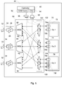
- FIG. 5 Further one embodiment is illustrated in figure 5 .
- This embodiment comprises further one WSS 80, further one service arrangement Eq 3 76, and one optical splitter S3 106.
- each port 52 and WSS 80 is a bi-directional optical amplifier arrangement 54 inserted.
- Said arrangement 54 comprises one optical amplifier 58 for amplifying the incoming optical signal on the optical fibre connected to the port 52 and one optical amplifier 56 for amplifying the outgoing optical signal.
- a port 52 is connected to a corresponding WSS 80.
- CO Z a WSS 80 will be handling the data traffic on said fibre and direct channels ⁇ z towards the WSS 80.
- the WSS 80 is configured to spread and direct the channels ⁇ z towards the optical splitter arrangement 100.
- the optical splitter arrangement 100 is configured by means of the hub controller 90 to control and direct the wavelength channels ⁇ z, from the optical splitter arrangement 100 to the correct MC-OMs, 78, of the service equipment arrangement 70 for optical traffic requesting a certain service.
- the hub controller may be configured to control the optical splitters 102, 103, 104 e.g.
- MC-OMs, 78 are plugged into the ports.
- Said MC-OMs 78 are configured to receive and transmit optical traffic on different wavelengths ⁇ , i.e.
- each of the MC-OMs supports a set of said channels ⁇ 1 - ⁇ 70 , in both receive and transmit direction.
- the controller has more flexibility and freedom, compared to prior art, to select and control how to support a specific service by means of the access equipment having tuneable transmitters connected to different CO:s.
- hub embodiments comprise only two or three WSSs 80 and two or three service equipments in the service equipment arrangement 100.
- the number of WSSs and Equipments at a hub site may be large, e.g. 10 - 100 WSSs.
- the splitter sizes are limited. For example, a 16:16 splitter has about 14 dB insertion loss and combined with the WSS insertion loss of 5 dB or so, a 0 dBm per channel output power of the OM would have to be amplified at the WSS common port, to be able to bridge the fibre and subsequent WSS loss budget.
- Such splitter sizes are also in line with typical WSS port numbers (4-23).
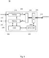
- FIG. 6 illustrates an embodiment of an optical transceiver module 78, e.g. a Single-Channel Module or Multi-Channel Optical Module (MC-OM) 78.
- Said MC-OM 78 comprises a housing 200, which may have a number of ports, contacts and/or interfaces for enabling connection to other physical entities which the device 78 interacts with.
- the housing 200 of the MC-OM 78 may have an optical port 210, a first electrical contact 212 and a second electrical contact.
- the MC-OM 78 further may comprise a transmitter array 216 and a receiver array 218 for enabling the transceiver functionality.
- a filter 220 is arranged for directing the received (via the optical port 210) wavelength or wavelengths of interest ⁇ x, ⁇ y and ⁇ oam to filter 222 and the Gigabit-Capable Passive Optical Network Optical Network Termination (GPON ONT) unit 226 and the Operation, Administration and Maintenance OAM unit 224, which typically is a digital processor, microprocessor, etc.
- the OAM 224 is also able to control and tune the TxArray 224 and the RxArray 218 to wavelengths of interest.
- a switching filter 222 directs incoming wavelength channels ⁇ x, ⁇ y onto the RxArray 218 that converts the modulated information from the optical domain into the electrical domain for further forwarding as electrical signals via the second electrical contact 214.
- the TxArray 216 operates in the other, opposite, direction.
- the transmitter array 216 receives via the first electrical contact 212 information, e.g generated by a data information processing device (not shown), to be sent and converts it to the optical domain.
- the TxArray 216 is capable to transmit received information onto modulated wavelengths channels in dependence of the destination of the information, i.e. each destination has one or more dedicated wavelengths ⁇ x, ⁇ y.
- the switching filter 222 and optical filter 220 direct the transmitted wavelengths via the optical port 210 for further transmission via the optical splitters (102, 104 in figure 2 ) and the WSSs (80 in figure 2 ) to the CO connected ports (e.g. 52 in figures 2-5 ).
- a point-to-multipoint (p2mp) mechanism like GPON (or Ethernet PON etc) is beneficial since only one OAM connectivity port is needed ie GPON OLT (Optical Line Terminal) transceiver (see 96 in figure 3 ).
- the MC-OMs need to have an internal optical filter 220 to filter out the OAM wavelength or wavelengths ⁇ oam in addition to a GPON ONT transceiver 226 and OAM device 224 (e.g. a microprocessor).
- control plane communication between the hub controller 90 and the hub node equipments to set up new (e.g. multi-layer) connections.
- Such control plane interface to the hub controller is not illustrated and is considered to not be involved in this invention.
- the hub controller 90 (see figures 3 or 4 ) provided with an Operation, Administration and Maintenance connectivity software module (OAM Conn) 92 and a GPON OLT transceiver 96 is capable of communicating in the optical layer via dedicated control wavelength channels ⁇ oam with the OAM 224 for handling, monitoring and controlling the MC-OM 78.
- the filter 220 is capable of directing said OAM wavelength(-s) ⁇ oam to the GPON ONT 226 which converts the control information carried by the OAM wavelength (-s) ⁇ oam to digitally processable electrical signals.
- the OAM device 224 may communicate via the GPON ONT 226 that converts digitally processable electrical signals to modulated OAM wavelength (-s) ⁇ oam, which are directed to the optical filter 220 that directs the transmitted wavelengths ⁇ oam via the optical port 210 for further transmission via the optical splitters (102, 104 in figure 2 ) to the OAM Conn (see 92 in figure 3 ) and/or the hub controller (see 90 in figure 3 ).
- Said one or more OAM wavelengths ⁇ oam, or control wavelength channels are indicated by dash-dot-dot lines in figures 2 - 5 , and this configuration enables p2mp physical (out-of-band) OAM communication to the MC-OMs 78.
- MC-OMs are important in the case the hub equipments are not managed by the same operator managing an optical network, e.g. a Metnet, so that the MC-OMs cannot be managed from the electrical side.
- a clear hub side transport service demarcation for the MC-OMs is needed in order to assure that the agreed service level is met.
- control devices i.e. hub controller 90, Operation, Administration and Maintenance connectivity software module (OAM Conn) 92 and Operation, Administration and Maintenance OAM unit 224
- hub controller 90 Operation, Administration and Maintenance connectivity software module
- OAM Conn Operation, Administration and Maintenance connectivity software module
- OAM unit 224 Operation, Administration and Maintenance OAM unit 224
- Different aspects of the invention may be implemented as a computer program product tangibly embodied in a machine readable storage device for execution by a programmable processor; and method steps may be performed by a programmable processor executing a program of instructions to perform functions of the invention by operating on input data and generating output.
- aspects of the invention may advantageously be implemented in one or more computer programs that are executable on a programmable system including at least one programmable processor coupled to receive data and instructions from, and to transmit data and instructions to, a data storage system, at least one input device, and at least one output device.
- Each computer program may be implemented in a high-level procedural or object-oriented programming language, or in machine language if desired; and in any case, the language may be a compiled or interpreted language.
- a processor will receive instructions and data from a read-only memory and/or a random access memory.
- Storage devices suitable for tangibly embodying computer program instructions and data include all forms of non-volatile memory, including by way of example semiconductor memory devices, such as EPROM, EEPROM, and flash memory devices; magnetic disks such internal hard disks and removable disks; magneto-optical disks; and CD-ROM disks. Any of the foregoing may be supplemented by, or incorporated in, specially -designed ASICs (Application Specific Integrated Circuits).
- FIG. 7 is a flowchart illustrating an example of a method 700 according to one aspect of the invention.
- Said hub device is provided with one or more optical ports connected to one or more service equipment arrangements 70 for digital processing the received data information.
- the hub device further comprises a wavelength switching means 60 configured to connect each channel to ports connected to the one or more of the service equipment arrangement 70.
- the method comprises:
- S710 Spreading and directing the channels to the different ports of the service equipment arrangements, in one direction, and network ports connected to the optical network, in the other, opposite, direction.
- the received optical wavelength channels are spread and directed to the different ports of the service equipment arrangements 70 by means of the wavelength switching means 60 comprising an optical splitter arrangement 100.
- the optical splitter arrangement 100 may comprise one or more optical splitters 102,104 for directing in both directions between the ports of the wavelength switching means 60 and the ports of the service equipment arrangement 70.
- the one or more optical ports may comprise an optical transceiver module 78, which is single- or multi-channel wavelength capable.
- FIG. 8 is a flowchart illustrating further one embodiment 702 according to the above descried method and aspect of the invention.
- This embodiment also involves the step S710, as described above. It also involves a step S720: S720: Controlling the optical splitter arrangement and the one or more optical splitters and/or optical transceiver modules.
- the hub controller 90 of the hub device is configured to control the optical splitter arrangement 100 and the one or more optical splitters 102,104 and/or optical transceiver modules, single- or multi-channel wavelength capable 78.
- FIG. 9 is a flowchart illustrating further one embodiment 704 according to the above descried method and aspect of the invention.
- This embodiment also involves the steps S710 and S720, as described above.
- the embodiment may also involve handling and controlling the Optical splitter arrangement 100 and the optical splitters 102, 104 therein and/or the optical transceiver modules, single- or multi-channel wavelength capable 78 by means of an Operation Administration and Maintenance connectivity software module 92.
- S720 comprises S722: Generating control signalling by means of the hub controller and a Operation Administration and Maintenance connectivity software module.
- the hub controller may be provided with a special unit 92 for controlling the operation, administration and maintenance of the connectivity of the optical transceiver modules 78, MC-OMs.
- the hub controller 90 is in this embodiment configured to control the operation of said unit 92.
- the unit 92 is also configured to perform S724: Sending the generated control signalling over one or more control wavelength channels.
- the unit is configured to send the generated control signalling to the Optical Splitter arrangement 100 and the optical splitters 102, 104 and/or optical transceiver modules, single- or multi-channel wavelength capable 78 over a control wavelength channel.
- the unit is provided with a port or interface 96.
- a point-to-multipoint (p2mp) mechanism like GPON (or EPON etc) is beneficial since only one OAM connectivity port is needed, i.e. GPON OLT transceiver (see 96 in figure 3 ).
- Each of the optical transceiver modules have an internal optical filter 220 to filter out the control channel wavelength or wavelengths ⁇ oam in addition to a GPON ONT transceiver 226 and OAM device 224, as described above.
- the hub controller 90 (see figures 3 or 4 ) provided with an Operation, Administration and Maintenance connectivity software module (OAM Conn) 92 and a GPON OLT transceiver 96 is capable of communicating in the optical layer via dedicated control wavelength channels ⁇ oam with the OAM 224 for handling, monitoring and controlling the optical transceiver modules ,MC-OM, 78.
- the filter 220 is capable of directing said OAM wavelength(-s) ⁇ oam to the GPON ONT 226 which converts the control information carried by the OAM wavelength (-s) to digitally processable electrical signals.
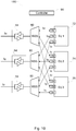
- a straightforward solution of a hub device is to connect each optical transceiver module to a WSS port.
- a hub device 150 is illustrated in figure 10 .
- the illustrated hub device 150 comprises bi-directional optical amplifier arrangements 54, controller 90, WSSs 80, optical transceiver modules OM and service equipment means 72, 74, 76.
- each service may have maximum 40 channels ⁇ x, ⁇ y or Az possible to direct to a particular CO (X, Y, Z).
- CO X may need to connect with 30 wavelengths from Equipment 1, 20 channels from Equipment 2, 42 channels from Equipment 3 etc. Since the wavelengths ⁇ x, ⁇ y and ⁇ z can not be shared between different WSS ports, this would result in equipment/wavelength underutilization, or would require more equipment to be installed.
- the present embodiments of invention propose to use N:N splitters in between a pool of MC-OM and WSSes.
- the splitters would then allow each channel of the pool of modules to be used at different WSSes. This way, efficient use of the optical channel resources can be achieved.
- the architecture in figure 10 imposes severe constraints.
- the OMs 78 are configured to receive and transmit optical traffic on different wavelengths channels A of the received wavelength channels ⁇ x, ⁇ y and Az. If the received wavelength channels ⁇ x, ⁇ y and ⁇ z together comprises channels ⁇ 1 - ⁇ 70 , each of the OMs may receive any of said channels and be tuned to one or more of channels ⁇ 1 - ⁇ 70 , by means of the flexibility provided by the configuration and position of the optical splitters between the WSSs and the ports of the service equipment means 72, 74, 76 in addition with the flexible control of the optical transceiver modules 78.
Landscapes
- Engineering & Computer Science (AREA)
- Computer Networks & Wireless Communication (AREA)
- Signal Processing (AREA)
- Optical Communication System (AREA)
- Small-Scale Networks (AREA)
Claims (15)
- Dispositif concentrateur de périphérie de services (50) pouvant être rattaché à un réseau optique transportant un trafic de données comprenant des informations de données sur des canaux de longueur d'onde optique, λ = λi (i = 1, 2, 3, ..., N), le dispositif concentrateur de périphérie de services (50) comprenant une pluralité de ports optiques (78a-g) pouvant être connectés à un ou plusieurs agencements d'équipements de services (70) pour le traitement numérique des informations de données, le dispositif concentrateur de périphérie de services (50) comprenant un moyen de commutation de longueur d'onde (60) configuré pour connecter chaque canal de longueur d'onde optique individuel à un port différent de la pluralité de ports optiques (78a-g), dans lequel le moyen de commutation de longueur d'onde (60) comprend un agencement de séparateur optique (100), dans lequel l'agencement de séparateur optique (100) comprend un ou plusieurs séparateurs optiques N:N (102, 104) pour étaler individuellement et diriger chaque canal de longueur d'onde optique individuel vers le port différent de la pluralité de ports optiques (78a-g) pouvant être connectés aux un ou plusieurs agencements d'équipements de services (70), dans une direction, et à un ou plusieurs ports de réseau (52), dans l'autre direction, et dans lequel les un ou plusieurs séparateurs optiques N:N (102, 104) sont commandés au moyen de filtres optiques contrôlables.
- Dispositif concentrateur de périphérie de services (50) selon la revendication 1, dans lequel le dispositif concentrateur de périphérie de services (50) comprend les un ou plusieurs agencements d'équipements de services (70).
- Dispositif concentrateur de périphérie de services (50) selon la revendication 1, dans lequel le moyen de commutation de longueur d'onde (60) comprend un ou plusieurs commutateurs sélectifs en longueur d'onde (80) pour diriger les canaux de longueur d'onde optique, A, vers l'agencement de séparateur optique (100), dans lequel les canaux de longueur d'onde optique, A, sont reçus à partir du réseau optique, et pour recevoir les canaux de longueur d'onde optique, A, à partir des un ou plusieurs agencements d'équipements de services (70) via la pluralité de ports optiques (78a-g) et distribuer lesdits canaux de longueur d'onde optique reçus, A, aux un ou plusieurs ports de réseau (52).
- Dispositif concentrateur de périphérie de services (50) selon la revendication 1, dans lequel l'agencement de séparateur optique (100) comprend les un ou plusieurs séparateurs optiques N:N (102, 104) pour diriger dans les deux directions entre des ports du moyen de commutation de longueur d'onde (60) et la pluralité de ports optiques (78a-g) pouvant être connectés aux un ou plusieurs agencements d'équipements de services (70).
- Dispositif concentrateur de périphérie de services (50) selon la revendication 1, dans lequel la pluralité de ports optiques (78a-g) pouvant être connectés aux un ou plusieurs agencements d'équipements de services (70) comprennent un module d'émetteur-récepteur optique (78), qui est capable de longueur d'onde à canal unique ou à canaux multiples.
- Dispositif concentrateur de périphérie de services (50) selon la revendication 1, dans lequel le dispositif concentrateur de périphérie de services (50) comprend un dispositif de commande de concentrateur (90) pour commander l'agencement de séparateur optique (100) et les un ou plusieurs séparateurs optiques N:N (102, 104), et/ou un module émetteur-récepteur optique (78), qui est capable de longueur d'onde à canal unique ou à canaux multiples.
- Dispositif concentrateur de périphérie de services (50) selon la revendication 6, dans lequel le dispositif de commande de concentrateur (90) est muni d'un module logiciel de connectivité d'exploitation, d'administration et de maintenance (92) pour manipuler et commander l'agencement de séparateur optique (100) et les un ou plusieurs séparateurs optiques N:N (102, 104) à l'intérieur, et le module émetteur-récepteur optique (78), qui est capable de longueur d'onde à canal unique ou à canaux multiples.
- Dispositif concentrateur de périphérie de services (50) selon la revendication 7, dans lequel le module logiciel de connectivité d'exploitation, d'administration et de maintenance (92) est muni en outre d'un port ou d'une interface (96) pour commander un fonctionnement et une fonction de l'agencement de séparateur optique (100) et des un ou plusieurs séparateurs optiques N:N (102, 104), le module émetteur-récepteur optique (78), qui est capable de longueur d'onde à canal unique ou à canaux multiples au moyen d'une signalisation de commande générée par le dispositif de commande de concentrateur (90) et transmise sur un canal de longueur d'onde de commande.
- Procédé dans un dispositif concentrateur de périphérie de services (50) pouvant être rattaché à un réseau optique transportant un trafic de données comprenant des informations de données sur des canaux de longueur d'onde optique, λ = λi (i = 1, 2, 3, ..., N), le dispositif concentrateur de périphérie de services (50) comprenant une pluralité de ports optiques (78a-g) connectés à un ou plusieurs agencements d'équipements de services (70) pour le traitement numérique des informations de données, le dispositif concentrateur de périphérie de services (50) comprenant un moyen de commutation de longueur d'onde (60) configuré pour connecter chaque canal de longueur d'onde optique individuel à un port différent de la pluralité de ports optiques (78a-g) connectés aux un ou plusieurs agencements d'équipements de services (70), ledit procédé comprenant :- l'étalement individuel (S710) et l'orientation (S710) de chaque canal de longueur d'onde optique individuel vers le port différent de la pluralité de ports optiques (78a-g) connectés aux un ou plusieurs agencements d'équipements de services (70) par l'intermédiaire du moyen de commutation de longueur d'onde (60) comprenant un agencement de séparateur optique (100), dans lequel l'agencement de séparateur optique comprend un ou plusieurs séparateurs optiques N:N (102, 104), dans une direction, et un ou plusieurs ports de réseau (52) connectés au réseau optique, dans l'autre direction, et dans lequel les un ou plusieurs séparateurs optiques N:N (102, 104) sont commandés au moyen de filtres optiques contrôlables.
- Procédé selon la revendication 9, dans lequel l'agencement de séparateur optique (100) comprend les un ou plusieurs séparateurs optiques N:N (102, 104) pour diriger dans les deux directions entre des ports du moyen de commutation de longueur d'onde (60) et la pluralité de ports optiques (78a-g) pouvant être connectés aux un ou plusieurs agencements d'équipements de services (70).
- Procédé selon la revendication 9, dans lequel la pluralité de ports optiques (78a-g) connectés aux un ou plusieurs agencements d'équipements de services (70) comprennent un module d'émetteur-récepteur optique (78), qui est capable de longueur d'onde à canal unique ou à canaux multiples.
- Procédé selon la revendication 9, dans lequel le dispositif concentrateur de périphérie de services (50) comprend un dispositif de commande de concentrateur (90) pour commander l'agencement de séparateur optique (100) et les un ou plusieurs séparateurs optiques N:N (102, 104), et/ou un module émetteur-récepteur optique (78), qui est capable de longueur d'onde à canal unique ou à canaux multiples, dans lequel le procédé comprend :- la commande (S720) de l'agencement de séparateur optique (100) et des un ou plusieurs séparateurs optiques N:N (102, 104) et/ou du module émetteur-récepteur optique (78).
- Procédé selon la revendication 12, le procédé comprenant la manipulation et la commande de l'agencement de séparateur optique (100) et des un ou plusieurs séparateurs optiques N:N (102, 104) à l'intérieur, et du module émetteur-récepteur optique (78), qui est capable de longueur d'onde à canal unique ou à canaux multiples, au moyen d'un module logiciel de connectivité d'exploitation, d'administration et de maintenance (92) connecté au dispositif de commande de concentrateur (90).
- Procédé selon la revendication 13, le procédé comprenant la manipulation et la commande de l'agencement de séparateur optique (100) et des un ou plusieurs séparateurs optiques N:N (102, 104) et/ou du module émetteur-récepteur optique (78), qui est capable de longueur d'onde à canal unique ou à canaux multiples, par- la génération (S722) d'une signalisation de commande au moyen du dispositif de commande de concentrateur (90) et du module logiciel de connectivité d'exploitation, d'administration et de maintenance (92) ; et- l'envoi (S724) de la signalisation de commande générée sur un ou plusieurs canaux de longueur d'onde de commande, λoam.
- Noeud dans un réseau de communication optique, dans lequel le noeud comprend le dispositif concentrateur de périphérie de services (50) selon l'une quelconque des revendications 1 à 8, qui est connecté au réseau de communication optique.
Applications Claiming Priority (2)
| Application Number | Priority Date | Filing Date | Title |
|---|---|---|---|
| US13/651,877 US9331807B2 (en) | 2012-10-15 | 2012-10-15 | Service edge hub device and methods in an optical network node |
| PCT/SE2013/050075 WO2014062110A1 (fr) | 2012-10-15 | 2013-01-30 | Procédés et dispositif concentrateur de périphérie de services dans un nœud de réseau optique |
Publications (2)
| Publication Number | Publication Date |
|---|---|
| EP2909959A1 EP2909959A1 (fr) | 2015-08-26 |
| EP2909959B1 true EP2909959B1 (fr) | 2019-04-17 |
Family
ID=47750787
Family Applications (1)
| Application Number | Title | Priority Date | Filing Date |
|---|---|---|---|
| EP13706318.6A Active EP2909959B1 (fr) | 2012-10-15 | 2013-01-30 | Procédés et dispositif concentrateur de périphérie de services dans un noeud de réseau optique |
Country Status (3)
| Country | Link |
|---|---|
| US (1) | US9331807B2 (fr) |
| EP (1) | EP2909959B1 (fr) |
| WO (1) | WO2014062110A1 (fr) |
Families Citing this family (13)
| Publication number | Priority date | Publication date | Assignee | Title |
|---|---|---|---|---|
| US20150033294A1 (en) * | 2013-07-26 | 2015-01-29 | Xtera Communications, Inc. | Network management system architecture of a telecommunications network |
| CN105282629A (zh) * | 2014-07-03 | 2016-01-27 | 中兴通讯股份有限公司 | 一种硅光交叉连接的控制方法和装置 |
| TW201611534A (zh) * | 2014-09-15 | 2016-03-16 | Chunghwa Telecom Co Ltd | 高速動態智慧型全光交換裝置 |
| WO2016060594A1 (fr) * | 2014-10-13 | 2016-04-21 | Telefonaktiebolaget L M Ericsson (Publ) | Commutateur sélectif en longueur d'onde optique, nœud de réseau optique, réseau optique et leurs procédés |
| US10038514B2 (en) * | 2014-12-23 | 2018-07-31 | Telefonaktiebolaget Lm Ericsson (Publ) | Datacentre for processing a service |
| US10425322B2 (en) | 2015-04-13 | 2019-09-24 | Ciena Corporation | Scalable broadband metro network architecture |
| US10667024B2 (en) * | 2015-06-02 | 2020-05-26 | Telefonaktiebolaget Lm Ericsson (Publ) | Transport network and method |
| EP3332579B1 (fr) * | 2015-08-06 | 2019-10-09 | Telefonaktiebolaget LM Ericsson (PUBL) | Commande de réseau de communications |
| EP3272131B1 (fr) | 2015-08-14 | 2023-10-04 | Hewlett Packard Enterprise Development LP | Signaux optiques |
| US10530518B2 (en) | 2015-09-30 | 2020-01-07 | Telefonaktiebolaget Lm Ericsson (Publ) | Network architecture, an optical communication network and use of an MD-WSS |
| CN108391186B (zh) * | 2018-04-19 | 2024-08-27 | 北京邮电大学 | 一种可重构光接入网系统 |
| CN112565095B (zh) * | 2020-12-11 | 2022-09-13 | 中盈优创资讯科技有限公司 | 一种互联网专线自动发现分析方法及装置 |
| US11817904B2 (en) * | 2021-03-25 | 2023-11-14 | Mellanox Technologies, Ltd. | Optical transceiver with reduced lane utilization |
Family Cites Families (19)
| Publication number | Priority date | Publication date | Assignee | Title |
|---|---|---|---|---|
| JPH06350646A (ja) * | 1993-06-08 | 1994-12-22 | Nec Corp | 光波長選択制御方式 |
| FR2743424B1 (fr) * | 1996-01-09 | 1998-03-27 | Instruments Sa | Routeur n x n de longueur d'onde, procede de routage optique et reseau de communications associes |
| US6826368B1 (en) * | 1998-10-20 | 2004-11-30 | Lucent Technologies Inc. | Wavelength division multiplexing (WDM) with multi-frequency lasers and optical couplers |
| US20020186432A1 (en) * | 2001-06-07 | 2002-12-12 | Roorda Peter David | Architecture for a photonic transport network |
| US7110671B1 (en) * | 2001-12-03 | 2006-09-19 | Cheetah Omni, Llc | Method and apparatus for scheduling communication using a star switching fabric |
| US7308197B1 (en) * | 2003-01-31 | 2007-12-11 | Ciena Corporation | Modular add/drop multiplexer including a wavelength selective switch |
| US7408639B1 (en) * | 2004-04-23 | 2008-08-05 | Nistica, Inc. | Tunable optical routing systems |
| US8190027B2 (en) * | 2006-07-12 | 2012-05-29 | Tellabs Operations, Inc. | Multifunctional and reconfigurable optical node and optical network |
| US7983560B2 (en) * | 2005-10-11 | 2011-07-19 | Dynamic Method Enterprises Limited | Modular WSS-based communications system with colorless add/drop interfaces |
| DE102006008404B4 (de) * | 2006-02-21 | 2011-04-14 | Adva Ag Optical Networking | Optische Schaltungsstrukturen zur Realisierung eines Knotens höherer Ordnung in einem optischen Übertragungsnetzwerk sowie Basis- und Erweiterungsschaltungsstruktur |
| WO2008031452A1 (fr) * | 2006-09-11 | 2008-03-20 | Telefonaktiebolaget Lm Ericsson (Publ) | Réseau de communication |
| JP4882712B2 (ja) * | 2006-12-07 | 2012-02-22 | 富士通株式会社 | 光クロスコネクト装置 |
| KR100875934B1 (ko) | 2007-06-25 | 2008-12-26 | 한국전자통신연구원 | 멀티링 네트워크 운영방법 및 장치 |
| DE602007013576D1 (de) * | 2007-11-21 | 2011-05-12 | Nokia Siemens Networks Oy | Photonischer Crossconnect |
| US8625993B2 (en) * | 2008-01-08 | 2014-01-07 | Ciena Corporation | Wavelength-switched optical add-drop multiplexer with wavelength broadcasting capability |
| US8625994B2 (en) * | 2008-03-11 | 2014-01-07 | Ciena Corporation | Directionless reconfigurable optical add-drop multiplexer systems and methods |
| US8699877B2 (en) * | 2008-06-19 | 2014-04-15 | Xieon Networks S.A.R.L. | Wavelength division multiplex terminal with automatic configuration and supervision of switch connections |
| WO2010000750A1 (fr) * | 2008-06-30 | 2010-01-07 | Alcatel Lucent | Dispositif de commutation de signaux optiques |
| JP5521168B2 (ja) * | 2010-12-09 | 2014-06-11 | 株式会社日立製作所 | 光伝送装置及び光伝送システム |
-
2012
- 2012-10-15 US US13/651,877 patent/US9331807B2/en not_active Expired - Fee Related
-
2013
- 2013-01-30 WO PCT/SE2013/050075 patent/WO2014062110A1/fr not_active Ceased
- 2013-01-30 EP EP13706318.6A patent/EP2909959B1/fr active Active
Non-Patent Citations (1)
| Title |
|---|
| None * |
Also Published As
| Publication number | Publication date |
|---|---|
| WO2014062110A1 (fr) | 2014-04-24 |
| US20140105600A1 (en) | 2014-04-17 |
| US9331807B2 (en) | 2016-05-03 |
| EP2909959A1 (fr) | 2015-08-26 |
Similar Documents
| Publication | Publication Date | Title |
|---|---|---|
| EP2909959B1 (fr) | Procédés et dispositif concentrateur de périphérie de services dans un noeud de réseau optique | |
| US7706688B2 (en) | Wavelength reconfigurable optical network | |
| US8861957B2 (en) | Optical access network | |
| US7130541B2 (en) | System and method for communicating optical signals upstream and downstream between a data service provider and subscriber | |
| US7499651B2 (en) | Upgradeable passive optical network | |
| US7684705B2 (en) | Distribution node for a wavelength-sharing network | |
| JP2026026158A (ja) | 光通信システム、光通信装置、制御装置、光通信方法及び光通信制御方法 | |
| KR102479083B1 (ko) | 단일 섬유 스트랜드를 통한 2-방향 데이터 전송 시스템, 장치 및 방법 | |
| US7546036B2 (en) | Hybrid passive optical network using shared wavelengths | |
| GB2452180A (en) | Optical access network system | |
| CN107071592B (zh) | 通信方法和通信系统 | |
| US7286756B1 (en) | DWDM system with IP telephony provisioning at remote locations | |
| Jinno et al. | IP traffic offloading to elastic optical layer using multi-flow optical transponder | |
| US12477255B2 (en) | Optical communication apparatus, optical communication system and optical communication method | |
| US20250007639A1 (en) | Establishing a transmission functionality for providing, via a telecommunications network, a communication or connectivity service between a first location and a second location based on optical data transmission of a user-defined optical signal | |
| US8761611B2 (en) | Wavelength assignment for multiple operator support | |
| US20080138063A1 (en) | System and Method for Protecting an Optical Network | |
| US12328537B2 (en) | Optical communication apparatus, optical communication system and optical communication method | |
| US20070077069A1 (en) | System and method for communicating optical signals upstream and downstream between a data service provider and subscribers | |
| CA2593891C (fr) | Reseau optique a longueur d'onde reconfigurable | |
| Gutierrez et al. | Next generation optical access networks | |
| Ellinas et al. | Advanced architectures for PON supporting Fi-Wi convergence | |
| US12598000B2 (en) | Subscriber apparatus, optical communication system and optical signal monitoring method | |
| Zhang et al. | Strategy and development of PON and UniPON in China Mobile | |
| BUTTABONI | Dynamic bandwidth and wavelength allocation strategies for long reach WDM TDM passive optical network |
Legal Events
| Date | Code | Title | Description |
|---|---|---|---|
| PUAI | Public reference made under article 153(3) epc to a published international application that has entered the european phase |
Free format text: ORIGINAL CODE: 0009012 |
|
| 17P | Request for examination filed |
Effective date: 20150506 |
|
| AK | Designated contracting states |
Kind code of ref document: A1 Designated state(s): AL AT BE BG CH CY CZ DE DK EE ES FI FR GB GR HR HU IE IS IT LI LT LU LV MC MK MT NL NO PL PT RO RS SE SI SK SM TR |
|
| AX | Request for extension of the european patent |
Extension state: BA ME |
|
| DAX | Request for extension of the european patent (deleted) | ||
| STAA | Information on the status of an ep patent application or granted ep patent |
Free format text: STATUS: EXAMINATION IS IN PROGRESS |
|
| 17Q | First examination report despatched |
Effective date: 20180118 |
|
| GRAP | Despatch of communication of intention to grant a patent |
Free format text: ORIGINAL CODE: EPIDOSNIGR1 |
|
| STAA | Information on the status of an ep patent application or granted ep patent |
Free format text: STATUS: GRANT OF PATENT IS INTENDED |
|
| INTG | Intention to grant announced |
Effective date: 20190116 |
|
| GRAS | Grant fee paid |
Free format text: ORIGINAL CODE: EPIDOSNIGR3 |
|
| GRAA | (expected) grant |
Free format text: ORIGINAL CODE: 0009210 |
|
| STAA | Information on the status of an ep patent application or granted ep patent |
Free format text: STATUS: THE PATENT HAS BEEN GRANTED |
|
| AK | Designated contracting states |
Kind code of ref document: B1 Designated state(s): AL AT BE BG CH CY CZ DE DK EE ES FI FR GB GR HR HU IE IS IT LI LT LU LV MC MK MT NL NO PL PT RO RS SE SI SK SM TR |
|
| REG | Reference to a national code |
Ref country code: GB Ref legal event code: FG4D |
|
| REG | Reference to a national code |
Ref country code: CH Ref legal event code: EP |
|
| REG | Reference to a national code |
Ref country code: DE Ref legal event code: R096 Ref document number: 602013053980 Country of ref document: DE |
|
| REG | Reference to a national code |
Ref country code: AT Ref legal event code: REF Ref document number: 1122710 Country of ref document: AT Kind code of ref document: T Effective date: 20190515 Ref country code: IE Ref legal event code: FG4D |
|
| REG | Reference to a national code |
Ref country code: NL Ref legal event code: FP |
|
| REG | Reference to a national code |
Ref country code: LT Ref legal event code: MG4D |
|
| PG25 | Lapsed in a contracting state [announced via postgrant information from national office to epo] |
Ref country code: FI Free format text: LAPSE BECAUSE OF FAILURE TO SUBMIT A TRANSLATION OF THE DESCRIPTION OR TO PAY THE FEE WITHIN THE PRESCRIBED TIME-LIMIT Effective date: 20190417 Ref country code: LT Free format text: LAPSE BECAUSE OF FAILURE TO SUBMIT A TRANSLATION OF THE DESCRIPTION OR TO PAY THE FEE WITHIN THE PRESCRIBED TIME-LIMIT Effective date: 20190417 Ref country code: ES Free format text: LAPSE BECAUSE OF FAILURE TO SUBMIT A TRANSLATION OF THE DESCRIPTION OR TO PAY THE FEE WITHIN THE PRESCRIBED TIME-LIMIT Effective date: 20190417 Ref country code: HR Free format text: LAPSE BECAUSE OF FAILURE TO SUBMIT A TRANSLATION OF THE DESCRIPTION OR TO PAY THE FEE WITHIN THE PRESCRIBED TIME-LIMIT Effective date: 20190417 Ref country code: PT Free format text: LAPSE BECAUSE OF FAILURE TO SUBMIT A TRANSLATION OF THE DESCRIPTION OR TO PAY THE FEE WITHIN THE PRESCRIBED TIME-LIMIT Effective date: 20190817 Ref country code: NO Free format text: LAPSE BECAUSE OF FAILURE TO SUBMIT A TRANSLATION OF THE DESCRIPTION OR TO PAY THE FEE WITHIN THE PRESCRIBED TIME-LIMIT Effective date: 20190717 Ref country code: SE Free format text: LAPSE BECAUSE OF FAILURE TO SUBMIT A TRANSLATION OF THE DESCRIPTION OR TO PAY THE FEE WITHIN THE PRESCRIBED TIME-LIMIT Effective date: 20190417 Ref country code: AL Free format text: LAPSE BECAUSE OF FAILURE TO SUBMIT A TRANSLATION OF THE DESCRIPTION OR TO PAY THE FEE WITHIN THE PRESCRIBED TIME-LIMIT Effective date: 20190417 |
|
| PG25 | Lapsed in a contracting state [announced via postgrant information from national office to epo] |
Ref country code: LV Free format text: LAPSE BECAUSE OF FAILURE TO SUBMIT A TRANSLATION OF THE DESCRIPTION OR TO PAY THE FEE WITHIN THE PRESCRIBED TIME-LIMIT Effective date: 20190417 Ref country code: PL Free format text: LAPSE BECAUSE OF FAILURE TO SUBMIT A TRANSLATION OF THE DESCRIPTION OR TO PAY THE FEE WITHIN THE PRESCRIBED TIME-LIMIT Effective date: 20190417 Ref country code: GR Free format text: LAPSE BECAUSE OF FAILURE TO SUBMIT A TRANSLATION OF THE DESCRIPTION OR TO PAY THE FEE WITHIN THE PRESCRIBED TIME-LIMIT Effective date: 20190718 Ref country code: RS Free format text: LAPSE BECAUSE OF FAILURE TO SUBMIT A TRANSLATION OF THE DESCRIPTION OR TO PAY THE FEE WITHIN THE PRESCRIBED TIME-LIMIT Effective date: 20190417 Ref country code: BG Free format text: LAPSE BECAUSE OF FAILURE TO SUBMIT A TRANSLATION OF THE DESCRIPTION OR TO PAY THE FEE WITHIN THE PRESCRIBED TIME-LIMIT Effective date: 20190717 |
|
| REG | Reference to a national code |
Ref country code: AT Ref legal event code: MK05 Ref document number: 1122710 Country of ref document: AT Kind code of ref document: T Effective date: 20190417 |
|
| PG25 | Lapsed in a contracting state [announced via postgrant information from national office to epo] |
Ref country code: IS Free format text: LAPSE BECAUSE OF FAILURE TO SUBMIT A TRANSLATION OF THE DESCRIPTION OR TO PAY THE FEE WITHIN THE PRESCRIBED TIME-LIMIT Effective date: 20190817 |
|
| REG | Reference to a national code |
Ref country code: DE Ref legal event code: R097 Ref document number: 602013053980 Country of ref document: DE |
|
| PG25 | Lapsed in a contracting state [announced via postgrant information from national office to epo] |
Ref country code: RO Free format text: LAPSE BECAUSE OF FAILURE TO SUBMIT A TRANSLATION OF THE DESCRIPTION OR TO PAY THE FEE WITHIN THE PRESCRIBED TIME-LIMIT Effective date: 20190417 Ref country code: CZ Free format text: LAPSE BECAUSE OF FAILURE TO SUBMIT A TRANSLATION OF THE DESCRIPTION OR TO PAY THE FEE WITHIN THE PRESCRIBED TIME-LIMIT Effective date: 20190417 Ref country code: SK Free format text: LAPSE BECAUSE OF FAILURE TO SUBMIT A TRANSLATION OF THE DESCRIPTION OR TO PAY THE FEE WITHIN THE PRESCRIBED TIME-LIMIT Effective date: 20190417 Ref country code: AT Free format text: LAPSE BECAUSE OF FAILURE TO SUBMIT A TRANSLATION OF THE DESCRIPTION OR TO PAY THE FEE WITHIN THE PRESCRIBED TIME-LIMIT Effective date: 20190417 Ref country code: EE Free format text: LAPSE BECAUSE OF FAILURE TO SUBMIT A TRANSLATION OF THE DESCRIPTION OR TO PAY THE FEE WITHIN THE PRESCRIBED TIME-LIMIT Effective date: 20190417 Ref country code: DK Free format text: LAPSE BECAUSE OF FAILURE TO SUBMIT A TRANSLATION OF THE DESCRIPTION OR TO PAY THE FEE WITHIN THE PRESCRIBED TIME-LIMIT Effective date: 20190417 |
|
| PLBE | No opposition filed within time limit |
Free format text: ORIGINAL CODE: 0009261 |
|
| STAA | Information on the status of an ep patent application or granted ep patent |
Free format text: STATUS: NO OPPOSITION FILED WITHIN TIME LIMIT |
|
| PG25 | Lapsed in a contracting state [announced via postgrant information from national office to epo] |
Ref country code: IT Free format text: LAPSE BECAUSE OF FAILURE TO SUBMIT A TRANSLATION OF THE DESCRIPTION OR TO PAY THE FEE WITHIN THE PRESCRIBED TIME-LIMIT Effective date: 20190417 Ref country code: SM Free format text: LAPSE BECAUSE OF FAILURE TO SUBMIT A TRANSLATION OF THE DESCRIPTION OR TO PAY THE FEE WITHIN THE PRESCRIBED TIME-LIMIT Effective date: 20190417 |
|
| 26N | No opposition filed |
Effective date: 20200120 |
|
| PG25 | Lapsed in a contracting state [announced via postgrant information from national office to epo] |
Ref country code: TR Free format text: LAPSE BECAUSE OF FAILURE TO SUBMIT A TRANSLATION OF THE DESCRIPTION OR TO PAY THE FEE WITHIN THE PRESCRIBED TIME-LIMIT Effective date: 20190417 |
|
| PG25 | Lapsed in a contracting state [announced via postgrant information from national office to epo] |
Ref country code: SI Free format text: LAPSE BECAUSE OF FAILURE TO SUBMIT A TRANSLATION OF THE DESCRIPTION OR TO PAY THE FEE WITHIN THE PRESCRIBED TIME-LIMIT Effective date: 20190417 |
|
| PG25 | Lapsed in a contracting state [announced via postgrant information from national office to epo] |
Ref country code: MC Free format text: LAPSE BECAUSE OF FAILURE TO SUBMIT A TRANSLATION OF THE DESCRIPTION OR TO PAY THE FEE WITHIN THE PRESCRIBED TIME-LIMIT Effective date: 20190417 |
|
| REG | Reference to a national code |
Ref country code: CH Ref legal event code: PL |
|
| REG | Reference to a national code |
Ref country code: BE Ref legal event code: MM Effective date: 20200131 |
|
| PG25 | Lapsed in a contracting state [announced via postgrant information from national office to epo] |
Ref country code: FR Free format text: LAPSE BECAUSE OF NON-PAYMENT OF DUE FEES Effective date: 20200131 Ref country code: LU Free format text: LAPSE BECAUSE OF NON-PAYMENT OF DUE FEES Effective date: 20200130 |
|
| PG25 | Lapsed in a contracting state [announced via postgrant information from national office to epo] |
Ref country code: BE Free format text: LAPSE BECAUSE OF NON-PAYMENT OF DUE FEES Effective date: 20200131 Ref country code: CH Free format text: LAPSE BECAUSE OF NON-PAYMENT OF DUE FEES Effective date: 20200131 Ref country code: LI Free format text: LAPSE BECAUSE OF NON-PAYMENT OF DUE FEES Effective date: 20200131 |
|
| PG25 | Lapsed in a contracting state [announced via postgrant information from national office to epo] |
Ref country code: IE Free format text: LAPSE BECAUSE OF NON-PAYMENT OF DUE FEES Effective date: 20200130 |
|
| PG25 | Lapsed in a contracting state [announced via postgrant information from national office to epo] |
Ref country code: MT Free format text: LAPSE BECAUSE OF FAILURE TO SUBMIT A TRANSLATION OF THE DESCRIPTION OR TO PAY THE FEE WITHIN THE PRESCRIBED TIME-LIMIT Effective date: 20190417 Ref country code: CY Free format text: LAPSE BECAUSE OF FAILURE TO SUBMIT A TRANSLATION OF THE DESCRIPTION OR TO PAY THE FEE WITHIN THE PRESCRIBED TIME-LIMIT Effective date: 20190417 |
|
| PG25 | Lapsed in a contracting state [announced via postgrant information from national office to epo] |
Ref country code: MK Free format text: LAPSE BECAUSE OF FAILURE TO SUBMIT A TRANSLATION OF THE DESCRIPTION OR TO PAY THE FEE WITHIN THE PRESCRIBED TIME-LIMIT Effective date: 20190417 |
|
| PGFP | Annual fee paid to national office [announced via postgrant information from national office to epo] |
Ref country code: NL Payment date: 20250127 Year of fee payment: 13 |
|
| PGFP | Annual fee paid to national office [announced via postgrant information from national office to epo] |
Ref country code: DE Payment date: 20250129 Year of fee payment: 13 |
|
| PGFP | Annual fee paid to national office [announced via postgrant information from national office to epo] |
Ref country code: GB Payment date: 20250127 Year of fee payment: 13 |