EP2910155B1 - Dispositif d'ébouillantage destiné à extraire une capsule - Google Patents
Dispositif d'ébouillantage destiné à extraire une capsule Download PDFInfo
- Publication number
- EP2910155B1 EP2910155B1 EP15001007.2A EP15001007A EP2910155B1 EP 2910155 B1 EP2910155 B1 EP 2910155B1 EP 15001007 A EP15001007 A EP 15001007A EP 2910155 B1 EP2910155 B1 EP 2910155B1
- Authority
- EP
- European Patent Office
- Prior art keywords
- brewing chamber
- chamber element
- brewing
- perforation
- portion capsule
- Prior art date
- Legal status (The legal status is an assumption and is not a legal conclusion. Google has not performed a legal analysis and makes no representation as to the accuracy of the status listed.)
- Active
Links
Images





Classifications
-
- A—HUMAN NECESSITIES
- A47—FURNITURE; DOMESTIC ARTICLES OR APPLIANCES; COFFEE MILLS; SPICE MILLS; SUCTION CLEANERS IN GENERAL
- A47J—KITCHEN EQUIPMENT; COFFEE MILLS; SPICE MILLS; APPARATUS FOR MAKING BEVERAGES
- A47J31/00—Apparatus for making beverages
- A47J31/40—Beverage-making apparatus with dispensing means for adding a measured quantity of ingredients, e.g. coffee, water, sugar, cocoa, milk, tea
- A47J31/407—Beverage-making apparatus with dispensing means for adding a measured quantity of ingredients, e.g. coffee, water, sugar, cocoa, milk, tea with ingredient-containing cartridges; Cartridge-perforating means
-
- A—HUMAN NECESSITIES
- A47—FURNITURE; DOMESTIC ARTICLES OR APPLIANCES; COFFEE MILLS; SPICE MILLS; SUCTION CLEANERS IN GENERAL
- A47J—KITCHEN EQUIPMENT; COFFEE MILLS; SPICE MILLS; APPARATUS FOR MAKING BEVERAGES
- A47J31/00—Apparatus for making beverages
- A47J31/24—Coffee-making apparatus in which hot water is passed through the filter under pressure, i.e. in which the coffee grounds are extracted under pressure
- A47J31/34—Coffee-making apparatus in which hot water is passed through the filter under pressure, i.e. in which the coffee grounds are extracted under pressure with hot water under liquid pressure
- A47J31/36—Coffee-making apparatus in which hot water is passed through the filter under pressure, i.e. in which the coffee grounds are extracted under pressure with hot water under liquid pressure with mechanical pressure-producing means
- A47J31/3604—Coffee-making apparatus in which hot water is passed through the filter under pressure, i.e. in which the coffee grounds are extracted under pressure with hot water under liquid pressure with mechanical pressure-producing means with a mechanism arranged to move the brewing chamber between loading, infusing and ejecting stations
- A47J31/3623—Cartridges being employed
- A47J31/3628—Perforating means therefor
-
- A—HUMAN NECESSITIES
- A47—FURNITURE; DOMESTIC ARTICLES OR APPLIANCES; COFFEE MILLS; SPICE MILLS; SUCTION CLEANERS IN GENERAL
- A47J—KITCHEN EQUIPMENT; COFFEE MILLS; SPICE MILLS; APPARATUS FOR MAKING BEVERAGES
- A47J31/00—Apparatus for making beverages
- A47J31/24—Coffee-making apparatus in which hot water is passed through the filter under pressure, i.e. in which the coffee grounds are extracted under pressure
- A47J31/34—Coffee-making apparatus in which hot water is passed through the filter under pressure, i.e. in which the coffee grounds are extracted under pressure with hot water under liquid pressure
- A47J31/36—Coffee-making apparatus in which hot water is passed through the filter under pressure, i.e. in which the coffee grounds are extracted under pressure with hot water under liquid pressure with mechanical pressure-producing means
- A47J31/3604—Coffee-making apparatus in which hot water is passed through the filter under pressure, i.e. in which the coffee grounds are extracted under pressure with hot water under liquid pressure with mechanical pressure-producing means with a mechanism arranged to move the brewing chamber between loading, infusing and ejecting stations
- A47J31/3623—Cartridges being employed
- A47J31/3633—Means to perform transfer from a loading position to an infusing position
-
- A—HUMAN NECESSITIES
- A47—FURNITURE; DOMESTIC ARTICLES OR APPLIANCES; COFFEE MILLS; SPICE MILLS; SUCTION CLEANERS IN GENERAL
- A47J—KITCHEN EQUIPMENT; COFFEE MILLS; SPICE MILLS; APPARATUS FOR MAKING BEVERAGES
- A47J31/00—Apparatus for making beverages
- A47J31/44—Parts or details or accessories of beverage-making apparatus
- A47J31/4403—Constructional details
Definitions
- the present invention relates to a brewing device for extracting a portion capsule with a first brewing chamber element and a second brewing chamber element, the first and/or the second brewing chamber element being spaced apart from one another along an axial direction between a loading position in which the first and the second brewing chamber element are spaced apart and one Extraction position, in which the first and the second brewing chamber element form a substantially closed brewing chamber, is movable.
- a brewing device for a portion capsule which comprises a second brewing chamber element in the form of a receiving element with a cavity for accommodating the portion capsule and a first brewing chamber element in the form of a closure element for closing the cavity.
- the closure element comprises an injection arrangement for introducing extraction liquid into the portion capsule
- the receiving element comprises an extraction arrangement for removing the extraction liquid interacting with a beverage substance arranged in the portion capsule from the portion capsule and feeding it to a drinking vessel to provide a beverage.
- the closure element is transferred into a loading position in which it is at a distance from the receiving element.
- the portion capsule is then introduced into an intermediate space between the receiving element and the closure element and the closure element is then displaced in the direction of the receiving element along an axial direction, as a result of which the portion capsule is introduced into the cavity of the receiving element.
- the receiving element and the closure element form in the extraction position a substantially closed brewing chamber for extracting the portion capsule.
- the beverage substance includes, in particular, roast or instant coffee to be extracted.
- perforating means which perforate the portion capsule for introducing the extraction liquid or for draining off the beverage extract during or after the closing of the brewing chamber.
- Such a brewing device is known, for example, from the publication EP 1 369 069 A2 known.
- the perforation tips are covered by a spring-loaded, movable cover with corresponding holes.
- Other brewing devices are from the references EP 0 891 734 A1 and EP 1 500 357 A1 known.
- the disadvantage of such brewing devices is, on the one hand, that with a uniform perforation of the portion capsule in the area of the injection arrangement, the portion capsule is flowed through by the extraction liquid over the shortest path, i.e. essentially parallel to the axial direction, and at a comparatively high speed, so that there is only little interaction between of the beverage substance and the extraction liquid. If the capsule is not completely filled with the beverage substance, there is also the risk that the beverage substance will slide down in the capsule due to gravity and the extraction liquid will flow over the beverage substance in the direction of the outlet opening without any interaction worth mentioning. In addition, there is a potential risk of injury for the user of the brewing device if he can come into contact with the razor-sharp perforating means through the loading opening.
- the invention is therefore based on the object of providing a brewing device for extracting a portion capsule which does not have the disadvantages of the prior art and achieves a significantly improved interaction between the beverage substance and the extraction liquid compared to the prior art, whereby the taste quality of the extracted drink is improved.
- a comparatively safe and error-free insertion of the portion capsule should be made possible.
- this object is achieved by a brewing device according to claim 1 .
- the first brewing chamber element has a base area facing the second brewing chamber element, the first brewing chamber element having a plurality of first perforation means, the first perforation means being within an angular range of a maximum of 230 degrees around the arranged around a central point.
- the portion capsule is advantageously only perforated where the beverage substance is also arranged (which has slipped down, for example, due to the effect of gravity).
- the maximum angular range of 230 degrees ensures that an efficient extraction is achieved, even if the beverage substance that has slipped protrudes above the horizontal plane (the portion capsule is more than half filled with beverage substance).
- the first brewing chamber element preferably comprises at least four first perforation means in order to achieve the highest possible throughput of extraction liquid.
- the first perforating means are preferably arranged asymmetrically distributed with respect to a plane extending along the axial direction.
- the plane includes in particular the horizontal plane extending at right angles to the gravitational field and centrally through the brewing chamber.
- the first perforating means are arranged with a substantially constant radius around a central point of the base area.
- the portion capsule is not perforated centrally on the wall facing the first brewing chamber element, but rather in its edge region.
- the portion capsule is particularly stable in the edge area, for example due to the flange of the portion capsule and/or the connection to the side walls of the portion capsule, the material of the portion capsule, in particular the portion capsule lid, only recedes slightly at this point during the perforation process, so that a safer and easier perforating process is guaranteed.
- the first brewing chamber element comprises exactly one single first perforation means.
- a comparatively simple and safe insertion of the portion capsule is thus advantageously ensured in the loading position, since the risk of the portion capsule getting caught on perforation means in the region of the insertion opening is effectively avoided.
- the risk of injury for a user of the brewing device is significantly reduced compared to the prior art, since only a single first perforating means is present and, moreover, this one first perforating means is arranged at a distance from the insertion opening. If a user sticks a finger into the insertion opening, he will usually not be able to reach the first perforation means, or only with difficulty.
- the first perforation means is preferably arranged essentially in a lower edge region of the first brewing chamber element along the gravitational field, in order to create a maximum distance between the insertion opening and the first perforation means.
- one of the first perforating means also generates a comparatively large turbulence of the extraction liquid in the portion capsule, as well as the longest possible interaction distance, whereby the taste quality of the beverage to be extracted is positively influenced.
- the portion capsule is perforated in its lower region by the first perforating means, in which the beverage substance is always located due to the effect of gravity (even if the portion capsule is only partially filled with beverage substance).
- the portion capsule in the loading position the portion capsule is fed between the first and the second brewing chamber element along a loading direction, the loading direction being oriented essentially at right angles to the horizontal direction.
- the portion capsule is thus advantageously introduced into the brewing device with the assistance of gravity.
- a user only has to drop the portion capsule, which considerably simplifies the loading process.
- the first brewing chamber element is preferably inclined relative to the second brewing chamber element in the loading position in order to enable the brewing device to be loaded with a portion capsule as simply as possible.
- moving from the loading position to the extraction position includes, for example, an axial displacement of the first brewing chamber element along the axial direction, as well as a pivoting of the first brewing chamber element parallel to the second brewing chamber element.
- the first brewing chamber element is preferably pivoted through an angle of between 1 and 40 degrees, particularly preferably between 1 and 20 degrees and very particularly preferably between 1 and 10 degrees.
- the brewing device is designed in such a way that the portion capsule is perforated essentially sequentially by a plurality of first perforating means of the first brewing chamber element when the first and/or the second brewing chamber element is moved from the loading position to the extraction position .
- a reduction in the force required to perforate the portion capsule by means of the first perforating means can thus be achieved in an advantageous manner, since not all of the first perforating means penetrate into the portion capsule at the same time.
- the brewing device is designed in such a way that, when the first and/or the second brewing chamber element is moved from the loading position to the extraction position, the portion capsule is first released from the at least one first perforation means of the first brewing chamber element and only then from at least one second perforation means of the second brewing chamber element is perforated.
- the portion capsule is thus advantageously first perforated on the side of the first brewing chamber element and only then on the side of the second brewing chamber element. The total amount of force required to perforate the portion capsule can thus be reduced.
- the first brewing chamber element has a plurality of first perforation means.
- the portion capsule in the loading position the portion capsule is fed between the first and the second brewing chamber element along a loading direction, the first brewing chamber element having at least one first perforation means for perforating the portion capsule and the cutting plane of the at least a first perforating means is oriented substantially perpendicular to the loading direction.
- the risk of injury for a user of the brewing device is thus significantly reduced.
- a user who, for example, reaches into the area between the first and the second brewing chamber element with his finger along the loading direction, moves his finger perpendicularly to the cutting plane, so that the risk of a cut injury is reduced.
- the risk of the finger coming into direct contact with the cutting edge of the at least one first perforating means, which is designed in particular as a cutting knife, is reduced since the finger mainly only touches the blunt side of the cutting knife when moving along the loading direction.
- the wording “essentially perpendicular” means in particular that the cutting plane extends at least along a transverse direction perpendicular to the axial direction perpendicular to the loading direction.
- the angle between the cutting plane and the loading direction is preferably between 50 and 130 degrees, particularly preferably between 70 and 110 degrees and very particularly preferably between 80 and 100 degrees.
- the first brewing chamber element has a plurality of first perforation means.
- the brewing device has a feed opening, which is provided for feeding the portion capsule between the first and the second brewing chamber element along a loading direction, wherein preferably at least the one first perforation means with the smallest distance from the feed opening has a cutting plane which is aligned substantially perpendicular to the loading direction.
- a risk of injury for the user emanates in particular from the first perforation means, which is closest to the feed opening for loading the brewing device with a portion capsule compared to the other first perforation means, if more than one first perforation means are provided, so that alone through a corresponding Alignment of this at least one first perforation means, the risk of injury is significantly reduced.
- the at least one first perforation means is designed as a perforation tip, which protrudes from the first brewing chamber element essentially in the direction of the second brewing chamber element.
- the at least one perforation tip preferably has a substantially linear cross section along the axial direction, which cross section is preferably rectilinear or curved.
- the at least one perforation tip has an essentially triangular profile perpendicular to the axial direction. In this way, a comparatively simple perforation is possible with little effort, since the piercing resistance is comparatively low.
- the first brewing chamber element has a plurality of first perforation means, each of which is in the form of a perforation tip.
- the first brewing chamber element has a perforation element on an end side facing the second brewing chamber element, which comprises a central surface area which is integrally connected to the at least one perforation means along its circumference.
- the perforation element is produced in particular by buckling the at least one first perforation means in relation to the surface area.
- the perforation element has a plurality of first perforation means, each of which is designed in the form of a bent perforation point.
- the first brewing chamber element and in particular the perforation element has at least one water outlet opening in the surface area for feeding liquid into the portion capsule perforated by means of the at least one first perforation means, with the water outlet opening preferably being arranged substantially adjacent to the at least one first perforation means is.
- the extraction liquid is thus fed directly into the region of the perforation openings in the brewing chamber, so that the extraction liquid can flow into the portion capsule with almost no pressure loss.
- the perforation element has a plurality of water outlet openings which are each arranged adjacent to the first perforation means if the brewing device should have a plurality of first perforation means.
- the second brewing chamber element has at least one second perforation means, which is arranged asymmetrically relative to the plane and in particular relative to the horizontal plane, with the second perforation means preferably being arranged below the horizontal plane.
- an opening for draining the extraction liquid out of the portion capsule is thus advantageously produced in an advantageous manner.
- This opening is advantageously below the horizontal plane, so that the above-mentioned oblique flow through the portion capsule, i.e. the flow direction of the extraction liquid is inclined within the portion capsule compared to the axial direction, is supported and the taste quality of the extracted beverage is thus increased.
- the second perforating means comprises, for example, a cutting blade, a hollow needle or a point provided with channels.
- the second perforating means comprises a piercing tip which protrudes from the second brewing chamber element essentially in the direction of the first brewing chamber element and which is preferably provided with lateral grooves over at least a partial area.
- the lateral grooves facilitate the drainage of the extraction liquid from the portion capsule, since the extraction liquid can flow out of the portion capsule within the grooves between the second perforation means and the capsule material, in particular the material of the portion capsule base.
- the second perforation means is detachable and is coupled to the second brewing chamber element in particular via a latching and/or screw closure. This advantageously makes it easier to install and remove the second perforating means, for example for cleaning and service purposes.
- the second brewing chamber element comprises a hollow bell-shaped element for accommodating the portion capsule, with a base region of the bell-shaped element comprising at least one depression for draining extraction liquid from the portion capsule perforated by means of the second perforating means, with the second perforating means preferably being located in the region of the Depression is arranged and wherein the depression preferably opens into a drain channel for discharging the extraction liquid from the brewing chamber.
- the depression preferably comprises a support and/or column structure, as a result of which the portion capsule is securely spaced from the second brewing chamber element in the region of the depression. This prevents the cross section of the recess from being reduced by the capsule base, so that it is possible to ensure that the extraction liquid is drained away at all times.
- the first brewing chamber element has at least one first perforation means for perforating the portion capsule and that the brewing device has at least one spacer element which is designed in such a way that when the portion capsule is fed in between the first and the second brewing chamber element in the loading position, there is mechanical contact between of the portion capsule and the at least one first perforating means is prevented by the spacer element.
- the spacer element ensures a spacing of the portion capsule from the first brewing chamber element and from the at least one first perforation means during the feeding of the portion capsule. Trouble-free feeding of portion capsules is thus advantageously ensured.
- the first brewing chamber element has a plurality of first perforation means and/or a plurality of spacer elements.
- the first brewing chamber element comprises two first perforation means in the form of two perforation points, with the spacer element being arranged at least partially between the two perforation points and with the spacer element being spaced at least in the area between the two perforation points from the first brewing chamber element in the loading position and wherein the two perforation tips are preferably located along the gravitational field below the horizontal plane.
- the risk of the portion capsule getting caught on the first perforation points is thus advantageously further reduced, since the spacer element is spaced apart from the first brewing chamber element, particularly in the region of the first perforation points, and the portion capsule is thus protected from direct mechanical contact with the first perforation points.
- this provides effective finger protection, which protects a user reaching into the brewing chamber from coming into contact with the sharp first perforating means.
- the spacer element is attached to the first brewing chamber element and is at least partially elastically pretensioned in the direction of the second brewing chamber element, and preferably that the spacer element is designed such that it rests essentially completely against the first brewing chamber element in the extraction position.
- the spacer element is spaced from the first brewing chamber element in the loading position, while in the extraction position it rests against the first brewing chamber element, so that the extraction process is not impaired by the spacer element.
- the spacer element is elastically prestressed in the direction of the second brewing chamber element and is in particular designed to be flexible.
- the spacer element comprises a metal strip, the metal strip having a first end fastened to the first brewing chamber element and a free second end, the second end being in the loading position protrudes obliquely from the first brewing chamber element in the direction of the second brewing chamber element or, in the loading position, preferably rests against a surface of the first brewing chamber element that faces the second brewing chamber element.
- the free second end advantageously protrudes obliquely in the direction of the second brewing chamber element, so that the spacer element acts like a leaf spring, which keeps the portion capsule at a distance from the at least one first perforation means in the loading position.
- the metal strip additionally has a curvature in the direction of the second brewing chamber element, which increases the spring effect.
- the second end can again protrude obliquely in the direction of the second brewing chamber element or alternatively also rest against the first brewing chamber element in the loading position.
- the metal strip has a through hole. According to the invention it is provided that the metal strip is aligned essentially parallel to the loading direction.
- the extraction liquid preferably flows through the through-hole in the direction of the portion capsule, with the through-hole preferably being aligned with an extraction liquid access opening in the first brewing chamber element.
- the spacer element is designed in the same way as an alternative to the metal strip, but is made of a plastic material.
- a method for operating a brewing device wherein in a first method step a portion capsule is inserted between the first and the second brewing chamber element and wherein in a subsequent second method step the first and/or second brewing chamber element is moved essentially along the axial direction from the loading position to the Extraction position is moved and during the second method step the portion capsule below the horizontal plane is first perforated by at least one first perforating means of the first brewing chamber element and then the portion capsule is perforated by at least one second perforating means of the second brewing chamber element.
- the portion capsule is thus advantageously perforated in a lower region along the gravitational field.
- the beverage substance also slides into the lower area due to the effect of gravity.
- the first brewing chamber element alternatively has either exactly a single first perforation means or a plurality of first perforation means.
- the portion capsule is perforated sequentially by a plurality of first perforating means of the first brewing chamber element. In this way, the effort required to perforate the portion capsule and to close the brewing chamber is reduced if a plurality of first perforating means is used.
- the portion capsule is perforated by exactly one first perforating means.
- a comparatively simple and safe insertion of the portion capsule is thus advantageously ensured in the loading position.
- the first perforation means is preferably arranged essentially in a lower edge region of the first brewing chamber element along the gravitational field, in order to create a maximum distance between the insertion opening and the first perforation means.
- extraction liquid is introduced into the portion capsule only below the horizontal plane and/or within the angular range of a maximum of 230 degrees.
- extraction liquid is introduced into the portion capsule only where the beverage substance is located (which has slipped down, for example, due to the effect of gravity). It would therefore be conceivable that the portion capsule is also perforated above the horizontal plane or outside the angular range of 230 degrees, but the extraction liquid is introduced only below the horizontal plane and/or only within the angular range of maximum 230 degrees.
- a capsule lid of the portion capsule is perforated by the at least one first perforation means and that a capsule base of the portion capsule is perforated by the second perforation means.
- the portion capsule in the first method step is guided at least partially by a spacer element attached to the first brewing chamber element when it is fed between the first and second brewing chamber element in such a way that there is mechanical contact between the portion capsule and the at least one first perforation means through the spacer element is prevented.
- the portion capsule is kept at a distance from the first brewing chamber element and thus in particular also from the at least one first perforation means by the spacer element when it is inserted between the first and second brewing chamber element. The insertion process is thus less susceptible to faults, since the portion capsule is effectively prevented from getting caught on the at least one first perforating means.
- the first brewing chamber element has a plurality of first perforation means and/or a plurality of spacer elements.
- the spacer element protrudes at least partially from the first brewing chamber element in the direction of the second brewing chamber element, with the spacer element being brought into contact with the first brewing chamber element in the second method step.
- the spacer element is automatically pressed in the direction of the first brewing chamber element, so that the extraction process is not impaired by the spacer element.
- the spacer element thus does not protrude into the brewing chamber in the extraction position.
- the spacer element is in particular bent from an at least partially curved shape into a straight shape.
- a method for producing a brewing device in which, in a first production step, a perforation element having a central surface area and a plurality of first perforation means is punched out, wherein in a second production step the first perforation elements are bent in relation to the surface area in such a way that the first perforation means protrude at right angles from the surface area, and wherein in a third production step the perforation element is connected to the first brewing chamber element.
- the perforation element is preferably screwed to the first brewing chamber element.
- the perforation element includes in particular a sheet metal material.
- the perforation element is preferably provided with a plurality of water outlet openings in the surface area, with each of the water outlet openings being particularly preferably arranged adjacent to a first perforation element.
- at least one second perforation means is connected to the second brewing chamber element, with a latching and/or screw connection being used in particular.
- a brewing device according to the invention for preparing hot drinks, in particular coffee, milk, tea and/or chocolate drinks.
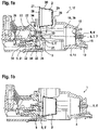
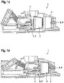
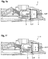
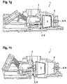
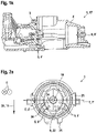
- FIGs 1a to 1k Schematic sectional views of a brewing device 1 for extracting a portion capsule 2 are shown according to a first.
- the brewing device 1 comprises a second brewing chamber element 4 embodied as a receiving element or partially hollow bell element 14 and a first brewing chamber element 3 embodied as a closure element 21 or piston axial direction 6 between an in Figures 1a and 1k illustrated loading position 17 and an in Figure 1f illustrated extraction position 11 movable.
- the portion capsule 2 comprises a truncated cone 30 made of plastic and designed in the shape of a pot.
- the truncated cone 30 is sealed airtight by means of a capsule lid 28 made of plastic and/or aluminum foil.
- a beverage substance in particular a roasted coffee powder that can be extracted by means of an extraction liquid, is located within the portion capsule 2 .
- the portion capsule 2 has a filter element, not shown, which is arranged (possibly at a distance from the capsule bottom 29) between the capsule bottom 29 and the beverage substance.
- the capsule cover 28 is glued or welded to the truncated cone 30 in the area of a capsule flange 27 .
- the first brewing chamber element 3 On the side facing the second brewing chamber element 4, the first brewing chamber element 3 has a perforation element 22, which comprises a substantially round base surface 9, on the peripheral area of which four first perforation means 5 are formed in the circumferential direction.
- the first perforating means 5 are provided with an almost constant radius around a central point 201 (see figure 8 ) on the base surface 9 of the first brewing chamber element 3 facing the second brewing chamber element 4 .
- the first perforation means 5 each comprise a perforation tip 5 ′, which protrudes from the base area 9 in the direction of the second brewing chamber element 4 .
- the first perforating means 5 are all arranged along the gravitational field 39 of the earth below a plane 7 designed as a horizontal plane 7'.
- the horizontal plane 7' extends essentially centrally through the brewing chamber 1' and essentially at right angles to the gravitational field 39.
- the brewing device 1 has only exactly one first perforation means 5, which is arranged along the gravitational field 39 below the horizontal plane 7'.
- the one first perforation means 5 is essentially in one along the Arranged gravity field 39 lower edge region of the first brewing chamber element 3 in order to produce a maximum distance between the feed opening 20 and the first perforation means 5.
- the first brewing chamber element 3 has a water supply channel 31, which opens into a bulge 32 formed between the first brewing chamber element 3 and the perforation element 22, so that extraction liquid supplied through the water supply duct 31 can be distributed via the bulge 32 to the four water outlet openings 24.
- the perforation element 22 is attached to the first brewing chamber element 3 by means of a screw 33 .
- the second brewing chamber element 4 has a second perforation means 8, which includes a piercing tip 8' pointing in the direction of the first brewing chamber element 3, which is arranged inside the cavity and is detachably connected to the second brewing chamber element 4 via a snap-in closure.
- the piercing tip 8 ′ is provided with lateral grooves which extend parallel to the axial direction 6 .
- the second brewing chamber element 4 has a recess 16 in the base area 15 of the cavity, into which a drainage channel 13 opens.
- the first brewing chamber element 3 is illustrated in the loading position 17 , ie the first brewing chamber element 3 is spaced apart from the second brewing chamber element 4 along the axial direction 6 .
- the portion capsule 2 is now inserted along a loading direction 18 by a user (not shown).
- a housing of the brewing device 1 designed as part of the second brewing chamber element 4 has a feed opening 20 through which the portion capsule 2 is inserted.
- the first brewing chamber element 3 is driven via a toggle joint 26 to move in the direction of the second brewing chamber element 4 .
- the continuous movement of the first brewing chamber element 3 in the direction of the second brewing chamber element 4 causes the capsule lid 28 to be perforated by the first perforating means 5 designed as perforating tips 5'.
- the capsule lid 28 is perforated by the first perforating means 5 only below the horizontal plane 7'.
- the capsule base 29 is not yet perforated at this point in time.
- the capsule lid 28 is perforated in a lower region along the gravitational field 39 only by the precisely one first perforating means 5 .
- the extraction process is initiated, ie the brewing chamber 1' is supplied with extraction liquid in the form of pressurized and heated water.
- the extraction liquid is conveyed through the water supply channel 31 and the bulge 32 to the water outlet openings 24 and arrives there through the perforation openings in the capsule cover 28 created by the first perforation means 5 into the portion capsule 2.
- the beverage substance is flowed through by the extraction liquid, so that a beverage extract is formed, which leaves the portion capsule 2 again through the perforation hole created in the capsule bottom 29 by means of the piercing spike 8' and passes through the recess 16 into the drain channel 13.
- the beverage extract is preferably fed directly to a drinking vessel (not shown), such as a coffee cup, by means of the discharge channel 13 .
- the extraction liquid flows through the portion capsule 2 in any case in the area of the beverage substance arranged in the portion capsule 2, even if it slides down in the portion capsule 2 due to the effect of gravity.
- the first brewing chamber element 3 is moved from the extraction position 11 parallel to the axial direction 6 back into the loading position 17 .
- This is based on Figures 1g to 1j illustrated.
- the used portion capsule 2 is pulled back by the first brewing chamber element 3 until the capsule flange 27 comes into contact with an ejector 35, not described in detail, whereby the portion capsule 2 disengages from the holding means 25 and, under the influence of gravity, independently from the area between the first and the second brewing chamber element 3, 4 falls, for example into a collecting container, not shown.
- FIGS 2a to 2c Schematic views of a first brewing chamber element 3 of a brewing device 1 according to a second embodiment are shown, wherein the brewing device 1 according to the second embodiment is essentially as shown in FIG Figures 1a to 1k illustrated brewing device 1 according to the first embodiment.
- the first perforation means 5 are designed as perforation tips 5 ′, which in the projection along the axial direction 6 have an almost linear cross section 36 which is curved along the circumference of the base area 9 .
- the perforation points 5' In a plane parallel to the axial direction 6, the perforation points 5' each have a triangular profile which is parallel to the cutting plane 19 runs, since the cutting edges of the perforation tips 5' are each formed by the legs 38 of the triangles.
- the perforation points 5 ′ are arranged in a plane perpendicular to the axial direction 6 each with an almost constant radius (the end face 9 is slightly oval instead of circular) around a central point 201 on the base area 9 .
- the perforation element 22 with base area 9 and perforation points 5' is punched out of sheet metal as part of a stamping process and the perforation points 5' are then bent in a kink manner relative to the base area 9 in such a way that the perforation points 5' protrude perpendicularly from the peripheral region of the base area 9.
- the perforation points 5 ′ are distributed along the peripheral region in such a way that they are distributed asymmetrically with respect to a plane 7 extending along the axial direction 6 , ie the first perforation means 5 are arranged exclusively below the plane 7 .
- the plane 7 includes in particular a horizontal plane 7 ′, which is formed essentially almost perpendicularly to the gravitational field 39 and/or to the loading direction 18 .
- Figure 2c the flow of the extraction liquid in the direction of the brewing chamber 1' is illustrated by means of arrows 42.
- FIG 3 is a schematic sectional view of a first brewing chamber element 3 of a brewing device 1 according to a third embodiment, wherein the brewing device 1 according to the third embodiment is essentially as shown in FIG Figures 2a to 2c illustrated brewing device 1 according to the second embodiment, in contrast to the second embodiment, the first perforating means 5, 5' having the smallest distance from the feed opening 20 has a cutting plane 19 which is aligned substantially perpendicular to the loading direction 18 and/or to the gravitational field 39.
- a finger 40 of a user who reaches into the brewing device 1 from above through the feed opening 20 thus only comes into contact with the blunt side surface 41 of this first perforating means 5, so that the risk of injury is considerably reduced.
- this first perforation means 5, 5' is also arranged below the horizontal plane 7' at the shortest distance from the feed opening 20.
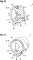
- FIGs 4a to 4d Schematic views of a first brewing chamber element 3 of a brewing device 1 according to the invention are shown according to a fourth embodiment, wherein the brewing device 1 according to the fourth embodiment essentially the in Figures 2a to 2c illustrated brewing device 1 according to the second embodiment, wherein the brewing device 1, in contrast to the second embodiment, has only two first perforation means 5, which are both arranged along the gravitational field 39 below the horizontal plane 7'.
- a spacer element 50 is arranged between the perforation tips 5'.
- the spacer element 50 comprises a metal strip 51 which extends essentially parallel to the loading direction 18 and which is fastened to the first brewing chamber element 3 with a first end 52 .
- the first end 52 as in Figure 4c can be seen, angled in the direction of the first brewing chamber element 3 and firmly clamped in a recess 55 of the first brewing chamber element 3 .
- the second end 53 of the metal strip 51 is a free end without attachment to the first brewing chamber element 3.
- the metal strip 51 has a curvature in the direction of the second brewing chamber element 4 between the first and the second end 52, 53. This curvature serves to space a portion capsule 2, which is inserted in the loading position 17 between the first and second brewing chamber element 3, 4, from the first brewing chamber element 3, so that the portion capsule 2 does not hang on the two perforation tips 5' during the insertion process remains.
- the spacer element 50 also has a through hole 54 which is essentially aligned with the water supply channel 31 of the first brewing chamber element 3 and allows the extraction liquid to be supplied to the portion capsule 2.
- FIGS 5a to 5c Schematic views of a first brewing chamber element 3 of a brewing device 1 according to the invention according to a fifth embodiment are shown, wherein the brewing device 1 according to the fifth embodiment essentially corresponds to that in FIG Figures 4a to 4d illustrated brewing device 1 according to the fourth embodiment, wherein the brewing device 1, in contrast to the fourth embodiment, has a spacer element 50, which does not have a curvature, but in which instead the free second end 53 in the loading position 17 is inclined in the direction of the second brewing chamber element 4 from the first Brewing chamber element 3 protrudes.
- the second end 53 is pivoted in the direction of the first brewing chamber element 3, so that the spacer element 50 comes into contact with the first brewing chamber element 3 essentially along its entire length (not shown in FIG the characters).
- FIG 6 is a schematic view of a first brewing chamber element 3 of a brewing device 1 according to a sixth embodiment, wherein the brewing device 1 according to the sixth embodiment is essentially the same as the brewing device 1 illustrated in Figures 1a to 1k according to the first embodiment and in the Figures 1a to 1k illustrated brewing device 1 can be used, in contrast to the first embodiment, the first brewing chamber element 3 according to the sixth embodiment has five first perforation means 5, which are arranged below the horizontal plane 7'.
- FIG 7 is a schematic view of a first brewing chamber element 3 of a brewing device 1 according to a seventh embodiment, wherein the brewing device 1 according to the seventh embodiment essentially corresponds to that in FIG Figures 1a to 1k illustrated brewing device 1 according to the first embodiment and shown in FIG Figures 1a to 1k illustrated brewing device 1 can be used, in contrast to the first embodiment, the first brewing chamber element 3 has only a single first perforation means 5 .
- This single first perforation means 5 is essentially arranged in a lower edge region of the first brewing chamber element 3 along the gravitational field 39 in order to create a maximum distance between the feed opening 20 and the first perforation means 3 and thus reduce the risk of injury for a user of the brewing device 1.
- FIG 8 is a schematic view of a first brewing chamber element 3 of a brewing device 1 according to an eighth embodiment, wherein the brewing device 1 according to the eighth embodiment is essentially as shown in FIG Figures 1a to 1k illustrated brewing device 1 according to the first embodiment and shown in FIG Figures 1a to 1k illustrated brewing device 1 can be used, in contrast to the first embodiment, the first brewing chamber element 3 has a plurality of first perforation means 5 in the form of perforation tips 5' (a total of seven first perforation means 5) which are arranged around a central point 201 on the end face 9 of the first brewing chamber element 3 which faces the second brewing chamber element 4.
- the first perforation means 5 are not only arranged below the horizontal plane 7, but instead are arranged with a substantially constant radius in an angular range 202 of approximately 230 degrees around the central point 201.
Landscapes
- Engineering & Computer Science (AREA)
- Food Science & Technology (AREA)
- Mechanical Engineering (AREA)
- Apparatus For Making Beverages (AREA)
- Packages (AREA)
- Medical Preparation Storing Or Oral Administration Devices (AREA)
Claims (5)
- . Dispositif d'infusion (1) pour l'extraction d'une capsule dosette (2), comprenant un premier élément de chambre d'infusion (3) et un deuxième élément de chambre d'infusion (4), le premier et/ou le deuxième élément de chambre d'infusion (3, 4) pouvant être déplacés le long d'une direction axiale (6) entre une position de chargement (17), dans laquelle le premier et le deuxième élément de chambre d'infusion (3, 4) sont espacés l'un de l'autre, et une position d'extraction (11), dans laquelle le premier et le deuxième élément de chambre d'infusion (3, 4) forment une chambre d'infusion essentiellement fermée (1') ; dans la position de chargement (17), une introduction de la capsule dosette (2) entre le premier et le deuxième élément de chambre d'infusion (3, 4) le long d'une direction de chargement (18) étant prévue, la direction de chargement (18) étant orientée à angle droit par rapport au plan horizontal (7'), caractérisé en ce que le premier élément de chambre d'infusion (3) présente au moins un premier moyen de perforation (5) pour la perforation de la capsule dosette (2), et en ce que le dispositif d'infusion (1) présente un élément d'espacement (50) qui est configuré de telle sorte que, lors de l'introduction de la capsule dosette (2) entre le premier et le deuxième élément de chambre d'infusion (3, 4) dans la position de chargement (17), un contact mécanique entre la capsule dosette (2) et l'au moins un premier moyen de perforation (5) est empêché par l'élément d'espacement (50), l'élément d'espacement (50) étant fixé au premier élément de chambre d'infusion (3) et étant au moins partiellement précontraint élastiquement en direction du deuxième élément de chambre d'infusion (4), l'élément d'espacement (50) comprenant une bande métallique (51), la bande métallique (51) présentant une première extrémité (52) fixée au premier élément de chambre d'infusion (3) et une deuxième extrémité libre (53), et la deuxième extrémité (53) dépassant en oblique du premier élément de chambre d'infusion (3) en direction du deuxième élément de chambre d'infusion (4) dans la position de chargement (17), la bande métallique (51) étant orientée essentiellement parallèlement à la direction de chargement (18).
- . Dispositif d'infusion (1) selon la revendication 1, la bande métallique (41) présentant une courbure en direction du deuxième élément de chambre d'infusion (4) .
- . Dispositif d'infusion (1) selon l'une quelconque des revendications précédentes, la bande métallique (51) présentant un trou traversant (54).
- . Dispositif d'infusion (1) selon l'une quelconque des revendications précédentes, le premier élément de chambre d'infusion (3) comprenant deux premiers moyens de perforation (5) sous la forme de pointes de perforation (5'), l'élément d'espacement (50) étant au moins partiellement agencé entre les deux pointes de perforation (5') et, dans la position de chargement (17), l'élément d'espacement (50) étant espacé du premier élément de chambre d'infusion (3) au moins dans la zone entre les deux pointes de perforation (5' ), et les deux pointes de perforation (5') étant de préférence agencées le long du champ de pesanteur (39) en dessous du plan horizontal (7').
- . Dispositif d'infusion (1) selon l'une quelconque des revendications précédentes, l'élément d'espacement (50) étant configuré de telle sorte qu'il s'applique essentiellement en totalité sur le premier élément de chambre d'infusion (3) dans la position d'extraction (11) .
Applications Claiming Priority (4)
| Application Number | Priority Date | Filing Date | Title |
|---|---|---|---|
| DE102010021849 | 2010-05-28 | ||
| DE102010044945A DE102010044945A1 (de) | 2010-05-28 | 2010-09-10 | Brühvorrichtung zum Extrahieren einer Portionskapsel, Verfahren zum Betrieb einer Brühvorrichtung, Verfahren zur Herstellung einer Brühvorrichtung und Verwendung einer Brühvorrichtung |
| PCT/EP2011/000271 WO2011147491A1 (fr) | 2010-05-28 | 2011-01-24 | Dispositif d'infusion destiné à la lixiviation d'une dosette |
| EP11702929.8A EP2575564B1 (fr) | 2010-05-28 | 2011-01-24 | Dispositif et procédé d'infusion destiné à la lixiviation d'une dosette |
Related Parent Applications (2)
| Application Number | Title | Priority Date | Filing Date |
|---|---|---|---|
| EP11702929.8A Division EP2575564B1 (fr) | 2010-05-28 | 2011-01-24 | Dispositif et procédé d'infusion destiné à la lixiviation d'une dosette |
| EP11702929.8A Division-Into EP2575564B1 (fr) | 2010-05-28 | 2011-01-24 | Dispositif et procédé d'infusion destiné à la lixiviation d'une dosette |
Publications (2)
| Publication Number | Publication Date |
|---|---|
| EP2910155A1 EP2910155A1 (fr) | 2015-08-26 |
| EP2910155B1 true EP2910155B1 (fr) | 2022-09-14 |
Family
ID=44534229
Family Applications (2)
| Application Number | Title | Priority Date | Filing Date |
|---|---|---|---|
| EP11702929.8A Active EP2575564B1 (fr) | 2010-05-28 | 2011-01-24 | Dispositif et procédé d'infusion destiné à la lixiviation d'une dosette |
| EP15001007.2A Active EP2910155B1 (fr) | 2010-05-28 | 2011-01-24 | Dispositif d'ébouillantage destiné à extraire une capsule |
Family Applications Before (1)
| Application Number | Title | Priority Date | Filing Date |
|---|---|---|---|
| EP11702929.8A Active EP2575564B1 (fr) | 2010-05-28 | 2011-01-24 | Dispositif et procédé d'infusion destiné à la lixiviation d'une dosette |
Country Status (12)
| Country | Link |
|---|---|
| US (2) | US10244886B2 (fr) |
| EP (2) | EP2575564B1 (fr) |
| JP (1) | JP5852102B2 (fr) |
| KR (1) | KR101993931B1 (fr) |
| CN (1) | CN103200849B (fr) |
| AU (1) | AU2011257614B2 (fr) |
| BR (1) | BR112012030361B1 (fr) |
| CA (1) | CA2800915C (fr) |
| DE (1) | DE102010044945A1 (fr) |
| RU (1) | RU2557491C2 (fr) |
| WO (1) | WO2011147491A1 (fr) |
| ZA (1) | ZA201208940B (fr) |
Families Citing this family (32)
| Publication number | Priority date | Publication date | Assignee | Title |
|---|---|---|---|---|
| DK3521209T3 (da) | 2010-07-22 | 2020-04-27 | K Fee System Gmbh | Portionskapsel med stregkode |
| EP2747609B1 (fr) * | 2011-08-25 | 2018-02-28 | Nestec S.A. | Système de positionnement de cartouche |
| US10034570B2 (en) * | 2011-11-09 | 2018-07-31 | LaVit Technology LLC | Capsule based system for preparing and dispensing a beverage |
| JP6086929B2 (ja) * | 2012-01-25 | 2017-03-01 | キュー・ビー・オー・コーヒー・ゲゼルシャフト・ミット・ベシュレンクテル・ハフツングQbo Coffee Gmbh | ブリューイングモジュール |
| DE102012006414A1 (de) * | 2012-03-30 | 2013-10-02 | Eugster/Frismag Ag Elektrohaushaltgeräte | Brühvorrichtung zum Extrahieren einer Portionskapsel und Verfahren zum Betrieb einer Brühvorrichtung |
| DE102012105282A1 (de) | 2012-06-18 | 2013-12-19 | K-Fee System Gmbh | Portionskapsel und Verfahren zur Herstellung eines Getränks mit einer Portionskapsel |
| DE102012108653A1 (de) | 2012-08-20 | 2014-02-20 | Eugster/Frismag Ag Elektrohaushaltgeräte | Brühvorrichtung und Verfahren zum Betrieb einer Brühvorrichtung |
| DE102012223291A1 (de) | 2012-12-14 | 2014-06-18 | K-Fee System Gmbh | Portionskapsel und Verfahren zur Herstellung eines Getränks mit einer Portionskapsel |
| DE102013215274A1 (de) | 2013-02-20 | 2014-08-21 | K-Fee System Gmbh | Portionskapsel und System |
| KR101477576B1 (ko) * | 2013-08-14 | 2014-12-30 | 정휘동 | 음료용 원재료 수용 캡슐로부터 음료를 추출하는 장치 |
| WO2016064791A1 (fr) | 2014-10-20 | 2016-04-28 | Keurig Green Mountain, Inc. | Support de cartouche pour machine de préparation de boissons |
| WO2016071796A1 (fr) * | 2014-11-06 | 2016-05-12 | Luigi Lavazza S.P.A. | Machine pour la préparation de produits liquides à l'aide de capsules |
| US10413113B2 (en) | 2014-11-06 | 2019-09-17 | Luigi Lavazza S.P.A. | Machine for the preparation of liquid products via capsules |
| DE102015201220A1 (de) * | 2015-01-26 | 2016-07-28 | BSH Hausgeräte GmbH | Brüheinheit für eine Kapselgetränkemaschine |
| MX2017010659A (es) | 2015-02-27 | 2017-11-16 | K Fee System Gmbh | Capsula para porcion individual con un elemento de filtro unido mediante sellado. |
| PT3307647T (pt) | 2015-06-10 | 2019-10-28 | K Fee System Gmbh | Cápsula de dose individual com um tecido não tecido em três camadas |
| KR20180030626A (ko) | 2015-07-13 | 2018-03-23 | 카-페 시스템 게엠베하 | 절취부를 가지는 필터 요소 |
| EP3350101B1 (fr) | 2015-09-18 | 2019-10-30 | K-fee System GmbH | Adaptateur de capsule |
| US20170135516A1 (en) * | 2015-11-12 | 2017-05-18 | Giancarlo Fantappiè | System for mixing and dispensing a beverage |
| ES2939370T3 (es) | 2016-01-12 | 2023-04-21 | Freezio Ag | Sistema de dispensador con soporte para cartucho |
| PT109303B (pt) | 2016-04-07 | 2021-02-15 | Novadelta Comercio Ind Cafes Sa | Dispositivo de extração com suporte de cápsula móvel |
| PT109304B (pt) * | 2016-04-07 | 2021-02-26 | Novadelta - Comércio E Indústria De Cafés, S.A. | Dispositivo de extração com câmara de recolha adaptada |
| CH712695A1 (de) | 2016-07-07 | 2018-01-15 | Mühlemann Ip Gmbh | Einportionenpackung zur Herstellung eines Getränks aus einem Getränkekonzentrat. |
| WO2018099983A1 (fr) | 2016-11-29 | 2018-06-07 | K-Fee System Gmbh | Dispositif d'infusion servant à l'extraction d'une capsule, machine à capsule et adaptateur de capsule |
| PL3644802T3 (pl) * | 2017-06-26 | 2021-11-02 | Freezio Ag | Urządzenie do produkcji napoju |
| CN111386060B (zh) | 2017-11-27 | 2022-07-05 | 弗里奇奥股份公司 | 料筒容纳部、料筒系统、饮料制备机以及用于生产饮料的方法 |
| CN111741700B (zh) * | 2018-03-14 | 2024-06-28 | 雀巢产品有限公司 | 具有非均匀配料提取配置的饮料机器 |
| KR102491513B1 (ko) | 2018-07-27 | 2023-01-27 | 지씨에스 게르만 캡슐 솔루션 게엠베하 | 음료 제조 기계에서 음료를 제조하기 위한 포션 캡슐을 제조하는 방법, 포션 캡슐, 및 음료 제조 기계와 포션 캡슐로 음료를 제조하는 방법 |
| EP3873304A1 (fr) | 2018-11-01 | 2021-09-08 | Société des Produits Nestlé S.A. | Système de capsule avec moyen de reconnaissance et mécanisme d'ouverture et d'injection adaptable |
| US12459728B2 (en) | 2018-11-22 | 2025-11-04 | Gcs German Capsule Solution Gmbh | Seal for a single serve capsule |
| US12102255B2 (en) | 2019-05-20 | 2024-10-01 | Eugster / Frismag Ag | Brewing apparatus and method for operating a brewing apparatus |
| US12514393B2 (en) * | 2022-06-08 | 2026-01-06 | Bartesian Corp. | Capsule holders for beverage dispensing apparatus |
Family Cites Families (44)
| Publication number | Priority date | Publication date | Assignee | Title |
|---|---|---|---|---|
| GB1215840A (en) | 1968-05-09 | 1970-12-16 | Universal Oil Prod Co | Apparatus for piercing containers for use in beverage producing machines |
| BE788061A (fr) | 1971-09-07 | 1973-02-26 | Douwe Egberts Tabaksfab | Koffiefiltering |
| US4158329A (en) * | 1978-04-24 | 1979-06-19 | Mcknight Robert J | Drip coffee brewer |
| DK162369C (da) | 1982-07-19 | 1992-03-23 | Mars G B Ltd | Fremgangsmaade og dispenser til fremstilling af en infusionsdrikkevare |
| NL8302168A (nl) | 1983-06-17 | 1985-01-16 | Wolfgang Gesen | Compact koffiefilter. |
| DE3803728A1 (de) | 1988-02-08 | 1989-08-17 | Braun Ag | Bruehgetraenkezubereitungsmaschine |
| JPH0820378A (ja) | 1991-11-11 | 1996-01-23 | Mori San Tour:Kk | 自転車用変速機構およびこれを用いた変速方法 |
| US5241219A (en) * | 1991-12-11 | 1993-08-31 | Amphenol Corporation | Current mode coupler |
| EP0891734B1 (fr) * | 1997-07-14 | 2000-10-04 | Societe Des Produits Nestle S.A. | Dispositif pour la confection de boisson |
| IT1321007B1 (it) * | 2000-02-07 | 2003-12-18 | Francesco Bonanno | Gruppo automatico per lo sfruttamento di caffe' e altre bevandemacinate ad azionamento idraulico |
| US6418779B1 (en) | 2000-06-09 | 2002-07-16 | Ceradex Corporation | Structure of oxygen sensor |
| DE60100785T2 (de) * | 2000-12-29 | 2004-07-15 | Sgl Italia S.R.L. | Kaffeemaschine |
| ITTO20010902A1 (it) * | 2001-09-21 | 2003-03-21 | Sgl Italia Srl | Macchina da caffe'. |
| ITTO20020481A1 (it) * | 2002-06-07 | 2003-12-09 | Sgl Italia Srl | Metodo e dispositivo di foratura di una capsula sigillata in una macchina da caffe'. |
| ES2257621T3 (es) * | 2003-07-23 | 2006-08-01 | Monodor S.A. | Procedimiento de preparacion de una bebida a partir de una capsula y dispositivo para la realizacion de dicho procedimiento. |
| ITTO20030885A1 (it) * | 2003-11-07 | 2005-05-08 | Sgl Italia Srl | Metodo e dispositivo di infusione per la realizzazione di una bevanda a base di caffe'. |
| ITTO20040476A1 (it) * | 2004-07-09 | 2004-10-09 | Sgl Italia Srl | Metodo per la preparazione di una bevanda a partire da materiale in polvere disposto in una capsula sigillata. |
| GB2416480B (en) | 2004-07-27 | 2007-12-27 | Kraft Foods R & D Inc | A system for the preparation of beverages |
| DE102004056224A1 (de) | 2004-11-19 | 2006-05-24 | Tchibo Gmbh | System mit einer Kaffeemaschine und einer Portionskapsel |
| DE102004056317A1 (de) | 2004-11-22 | 2006-05-24 | Schifferle, René | Getränkemaschine zur Herstellung eines Heissgetränks durch Aufbrühen und Extrahieren von in einer Kapsel abgepackten Substanzen |
| ITTO20050209A1 (it) | 2005-03-30 | 2006-09-30 | Sgl Italia Srl | Macchina percolatrice per la preparazione di una bevanda |
| CH697407B1 (de) * | 2005-08-19 | 2008-09-30 | Delica Ag | Mittel zum Perforieren einer Verpackungsfolie und Formwerkzeug zur Herstellung des Mittels. |
| PT1774878E (pt) * | 2005-10-14 | 2008-02-19 | Nestec Sa | Método de preparação de uma bebida a partir de uma cápsula |
| ES2344464T3 (es) | 2006-02-27 | 2010-08-27 | Nestec S.A. | Capsula con ingrediente de bebida con elemento para desviar la direccion del chorro. |
| ITFI20060194A1 (it) | 2006-08-04 | 2008-02-05 | Saeco Ipr Ltd | Dispositivo di infusione per la preparazione di bevande da capsule monodose |
| DE202006013189U1 (de) | 2006-08-25 | 2006-10-26 | Tchibo Gmbh | System mit einer Brühmaschine und einer Portionskapsel |
| CA2661501A1 (fr) | 2006-08-25 | 2008-02-28 | Delica Ag | Moyen pour transpercer un emballage-portion comportant un element d'extraction, dispositif d'extraction de l'element d'extraction contenu dans l'emballage-portion et procede de production dudit moyen |
| EP1944248B1 (fr) | 2007-01-15 | 2017-12-13 | Swiss Caffe Asia Ltd. | Capsule, moyen de pénétration du fond d'une capsule et dispositif de préparation d'une boisson |
| ATE454073T1 (de) * | 2007-03-06 | 2010-01-15 | Nestec Sa | Vorrichtung zur herstellung eines flüssigen lebensmittels aus einer kapsel |
| EP1974638A1 (fr) | 2007-03-29 | 2008-10-01 | Tchibo GmbH | Système doté d'une machine à boisson et de capsules de portions |
| CN100544647C (zh) | 2007-06-15 | 2009-09-30 | 宁波三A集团电器有限公司 | 咖啡机中咖啡包的自动脱落机构 |
| ITMO20070241A1 (it) | 2007-07-20 | 2009-01-21 | Saeco Ipr Ltd | Dispositivo per forare capsule porzionate |
| EP2330953B1 (fr) | 2008-09-02 | 2015-06-03 | Nestec S.A. | Procédé de préparation par centrifugation d'un liquide alimentaire contenu dans une capsule et système conçu pour un tel procédé |
| EP2177136A1 (fr) | 2008-10-17 | 2010-04-21 | Delica AG | Dispositif et agencement de préparation d'un produit alimentaire ou de dégustation liquide |
| EP2565132B1 (fr) | 2008-12-10 | 2015-10-28 | Delica AG | Capsule, corps de capsule et dispositif de préparation d'une boisson |
| US10004352B2 (en) | 2009-04-15 | 2018-06-26 | Qbo Coffee Gmbh | Device for discharging an extraction product out of a portion packaging; puncturing device and extraction apparatus |
| IT1397068B1 (it) | 2009-06-24 | 2012-12-28 | Swiss Caffe Asia Ltd | Dispositivo di foratura, particolarmente per capsule per la preparazione di bevande e simili. |
| ES2388892T3 (es) | 2009-12-18 | 2012-10-19 | Delica Ag | Dispositivo para preparar una bebida y cápsula |
| DE202010006556U1 (de) | 2010-05-06 | 2010-08-05 | Mahlich, Gotthard | Brüh- oder Zubereitungskammer für ein Getränkezubereitungsgerät |
| AU2011257556A1 (en) | 2010-05-28 | 2013-01-17 | K-Fee System Gmbh | Portion capsule for producing a beverage |
| US8361527B2 (en) | 2010-09-02 | 2013-01-29 | Keurig, Incorporated | Beverage cartridge |
| IT1403541B1 (it) * | 2011-01-31 | 2013-10-31 | Sarong Spa | Macchina erogatrice per bevande |
| GB2491154B (en) | 2011-05-24 | 2013-07-10 | Kraft Foods R & D Inc | Beverage/food product preparation systems |
| DE102012006414A1 (de) | 2012-03-30 | 2013-10-02 | Eugster/Frismag Ag Elektrohaushaltgeräte | Brühvorrichtung zum Extrahieren einer Portionskapsel und Verfahren zum Betrieb einer Brühvorrichtung |
-
2010
- 2010-09-10 DE DE102010044945A patent/DE102010044945A1/de active Pending
-
2011
- 2011-01-24 EP EP11702929.8A patent/EP2575564B1/fr active Active
- 2011-01-24 RU RU2012157627/12A patent/RU2557491C2/ru active
- 2011-01-24 BR BR112012030361-9A patent/BR112012030361B1/pt active IP Right Grant
- 2011-01-24 WO PCT/EP2011/000271 patent/WO2011147491A1/fr not_active Ceased
- 2011-01-24 AU AU2011257614A patent/AU2011257614B2/en active Active
- 2011-01-24 CN CN201180036897.8A patent/CN103200849B/zh active Active
- 2011-01-24 KR KR1020127032937A patent/KR101993931B1/ko active Active
- 2011-01-24 CA CA2800915A patent/CA2800915C/fr active Active
- 2011-01-24 EP EP15001007.2A patent/EP2910155B1/fr active Active
- 2011-01-24 JP JP2013511553A patent/JP5852102B2/ja active Active
-
2012
- 2012-11-27 ZA ZA2012/08940A patent/ZA201208940B/en unknown
- 2012-11-28 US US13/687,045 patent/US10244886B2/en active Active
-
2015
- 2015-05-27 US US14/723,032 patent/US10039412B2/en active Active
Also Published As
| Publication number | Publication date |
|---|---|
| AU2011257614A1 (en) | 2013-01-10 |
| EP2575564A1 (fr) | 2013-04-10 |
| KR101993931B1 (ko) | 2019-06-27 |
| WO2011147491A1 (fr) | 2011-12-01 |
| WO2011147491A8 (fr) | 2013-04-11 |
| CN103200849A (zh) | 2013-07-10 |
| DE102010044945A1 (de) | 2011-12-01 |
| US10039412B2 (en) | 2018-08-07 |
| RU2557491C2 (ru) | 2015-07-20 |
| AU2011257614B2 (en) | 2016-10-20 |
| JP5852102B2 (ja) | 2016-02-03 |
| JP2013529956A (ja) | 2013-07-25 |
| BR112012030361B1 (pt) | 2020-11-24 |
| EP2575564B1 (fr) | 2022-05-25 |
| EP2910155A1 (fr) | 2015-08-26 |
| CA2800915C (fr) | 2018-05-22 |
| CA2800915A1 (fr) | 2011-12-01 |
| RU2012157627A (ru) | 2014-07-10 |
| BR112012030361A2 (pt) | 2017-06-20 |
| ZA201208940B (en) | 2014-02-26 |
| US20130084376A1 (en) | 2013-04-04 |
| CN103200849B (zh) | 2016-12-07 |
| US10244886B2 (en) | 2019-04-02 |
| US20150257583A1 (en) | 2015-09-17 |
| KR20130098891A (ko) | 2013-09-05 |
Similar Documents
| Publication | Publication Date | Title |
|---|---|---|
| EP2575564B1 (fr) | Dispositif et procédé d'infusion destiné à la lixiviation d'une dosette | |
| EP2575566B1 (fr) | Dispositif d'infusion destiné à la lixiviation d'une dosette et procédé de fonctionnement d'un dispositif d'infusion | |
| EP2931629B1 (fr) | Systeme comprenant une machine de preparation et une capsule-dosette pour la preparation d'une boisson | |
| EP2512956B1 (fr) | Dosette et utilisation d'une dosette | |
| EP3023360B1 (fr) | Capsule et utilisation d'une capsule | |
| DE102009007553B4 (de) | Kapsel für die Zubereitung einer Flüssigkeit, insbesondere eines Kaffeegetränks | |
| DE202009009127U1 (de) | Befüllbare Kapsel mit verbesserten Dichtungseigenschaften | |
| DE69703235T2 (de) | Vorrichtung zur Herstellung eines Getränkes | |
| EP3052407B1 (fr) | Capsule et système de préparation d'un produit alimentaire liquide | |
| EP3046449A1 (fr) | Dispositif de perforation pour appareils d'extraction pour la préparation de produits d'infusion | |
| DE202015101266U1 (de) | Dichtung für Kaffeekapseln | |
| WO2013143974A1 (fr) | Dispositif d'infusion pour l'infusion d'une capsule de dosage et procédé de fonctionnement d'un dispositif d'infusion | |
| WO2011147591A1 (fr) | Dosette pour préparer une boisson | |
| DE202015100814U1 (de) | Dichtung für Kaffeekapseln | |
| DE202012012851U1 (de) | Brühvorrichtung zum Extrahieren einer Portionskapsel | |
| EP3310693B1 (fr) | Capsule pour la production des boissons | |
| EP2881175B1 (fr) | Pile de cassettes composée de cassettes individuelles, de préférence pour la réception de préparations pour analyses de laboratoire | |
| EP3487788B1 (fr) | Capsule pour la preparation d'une boisson | |
| EP2942312A1 (fr) | Récipient de fractionnement pour une capsule destinée à la préparation de boisson | |
| EP3118140B1 (fr) | Capsule de preparation d'un produit alimentaire liquide | |
| WO2014006019A2 (fr) | Système et procédé d'extraction d'une dosette | |
| DE19958395A1 (de) | Filtervorrichtung, insbesondere zur Trennung einer Flüssigkeit von festen Körpern | |
| DE202014105357U1 (de) | Ausgießer für Flaschen für Speiseöle und andere Flüssigkeiten | |
| DE102015000232A1 (de) | Dosiervorrichtung für eine Flüssigkeit | |
| EP1892342A2 (fr) | Dispositif de distribution d'agent actif |
Legal Events
| Date | Code | Title | Description |
|---|---|---|---|
| PUAI | Public reference made under article 153(3) epc to a published international application that has entered the european phase |
Free format text: ORIGINAL CODE: 0009012 |
|
| AC | Divisional application: reference to earlier application |
Ref document number: 2575564 Country of ref document: EP Kind code of ref document: P |
|
| AK | Designated contracting states |
Kind code of ref document: A1 Designated state(s): AL AT BE BG CH CY CZ DE DK EE ES FI FR GB GR HR HU IE IS IT LI LT LU LV MC MK MT NL NO PL PT RO RS SE SI SK SM TR |
|
| RIN1 | Information on inventor provided before grant (corrected) |
Inventor name: SEGER, CHRISTOF Inventor name: HUEPPI, MARCEL W. Inventor name: FISCHER, DANIEL |
|
| 17P | Request for examination filed |
Effective date: 20160225 |
|
| RBV | Designated contracting states (corrected) |
Designated state(s): AL AT BE BG CH CY CZ DE DK EE ES FI FR GB GR HR HU IE IS IT LI LT LU LV MC MK MT NL NO PL PT RO RS SE SI SK SM TR |
|
| STAA | Information on the status of an ep patent application or granted ep patent |
Free format text: STATUS: EXAMINATION IS IN PROGRESS |
|
| 17Q | First examination report despatched |
Effective date: 20190315 |
|
| GRAP | Despatch of communication of intention to grant a patent |
Free format text: ORIGINAL CODE: EPIDOSNIGR1 |
|
| STAA | Information on the status of an ep patent application or granted ep patent |
Free format text: STATUS: GRANT OF PATENT IS INTENDED |
|
| INTG | Intention to grant announced |
Effective date: 20220408 |
|
| GRAS | Grant fee paid |
Free format text: ORIGINAL CODE: EPIDOSNIGR3 |
|
| GRAA | (expected) grant |
Free format text: ORIGINAL CODE: 0009210 |
|
| STAA | Information on the status of an ep patent application or granted ep patent |
Free format text: STATUS: THE PATENT HAS BEEN GRANTED |
|
| AC | Divisional application: reference to earlier application |
Ref document number: 2575564 Country of ref document: EP Kind code of ref document: P |
|
| AK | Designated contracting states |
Kind code of ref document: B1 Designated state(s): AL AT BE BG CH CY CZ DE DK EE ES FI FR GB GR HR HU IE IS IT LI LT LU LV MC MK MT NL NO PL PT RO RS SE SI SK SM TR |
|
| REG | Reference to a national code |
Ref country code: GB Ref legal event code: FG4D Free format text: NOT ENGLISH |
|
| REG | Reference to a national code |
Ref country code: CH Ref legal event code: EP |
|
| REG | Reference to a national code |
Ref country code: DE Ref legal event code: R096 Ref document number: 502011017380 Country of ref document: DE |
|
| REG | Reference to a national code |
Ref country code: IE Ref legal event code: FG4D Free format text: LANGUAGE OF EP DOCUMENT: GERMAN |
|
| REG | Reference to a national code |
Ref country code: AT Ref legal event code: REF Ref document number: 1518188 Country of ref document: AT Kind code of ref document: T Effective date: 20221015 |
|
| REG | Reference to a national code |
Ref country code: NL Ref legal event code: FP |
|
| REG | Reference to a national code |
Ref country code: LT Ref legal event code: MG9D |
|
| PG25 | Lapsed in a contracting state [announced via postgrant information from national office to epo] |
Ref country code: SE Free format text: LAPSE BECAUSE OF FAILURE TO SUBMIT A TRANSLATION OF THE DESCRIPTION OR TO PAY THE FEE WITHIN THE PRESCRIBED TIME-LIMIT Effective date: 20220914 Ref country code: RS Free format text: LAPSE BECAUSE OF FAILURE TO SUBMIT A TRANSLATION OF THE DESCRIPTION OR TO PAY THE FEE WITHIN THE PRESCRIBED TIME-LIMIT Effective date: 20220914 Ref country code: NO Free format text: LAPSE BECAUSE OF FAILURE TO SUBMIT A TRANSLATION OF THE DESCRIPTION OR TO PAY THE FEE WITHIN THE PRESCRIBED TIME-LIMIT Effective date: 20221214 Ref country code: LV Free format text: LAPSE BECAUSE OF FAILURE TO SUBMIT A TRANSLATION OF THE DESCRIPTION OR TO PAY THE FEE WITHIN THE PRESCRIBED TIME-LIMIT Effective date: 20220914 Ref country code: LT Free format text: LAPSE BECAUSE OF FAILURE TO SUBMIT A TRANSLATION OF THE DESCRIPTION OR TO PAY THE FEE WITHIN THE PRESCRIBED TIME-LIMIT Effective date: 20220914 Ref country code: FI Free format text: LAPSE BECAUSE OF FAILURE TO SUBMIT A TRANSLATION OF THE DESCRIPTION OR TO PAY THE FEE WITHIN THE PRESCRIBED TIME-LIMIT Effective date: 20220914 |
|
| PG25 | Lapsed in a contracting state [announced via postgrant information from national office to epo] |
Ref country code: HR Free format text: LAPSE BECAUSE OF FAILURE TO SUBMIT A TRANSLATION OF THE DESCRIPTION OR TO PAY THE FEE WITHIN THE PRESCRIBED TIME-LIMIT Effective date: 20220914 Ref country code: GR Free format text: LAPSE BECAUSE OF FAILURE TO SUBMIT A TRANSLATION OF THE DESCRIPTION OR TO PAY THE FEE WITHIN THE PRESCRIBED TIME-LIMIT Effective date: 20221215 |
|
| PG25 | Lapsed in a contracting state [announced via postgrant information from national office to epo] |
Ref country code: SM Free format text: LAPSE BECAUSE OF FAILURE TO SUBMIT A TRANSLATION OF THE DESCRIPTION OR TO PAY THE FEE WITHIN THE PRESCRIBED TIME-LIMIT Effective date: 20220914 Ref country code: RO Free format text: LAPSE BECAUSE OF FAILURE TO SUBMIT A TRANSLATION OF THE DESCRIPTION OR TO PAY THE FEE WITHIN THE PRESCRIBED TIME-LIMIT Effective date: 20220914 Ref country code: PT Free format text: LAPSE BECAUSE OF FAILURE TO SUBMIT A TRANSLATION OF THE DESCRIPTION OR TO PAY THE FEE WITHIN THE PRESCRIBED TIME-LIMIT Effective date: 20230116 Ref country code: ES Free format text: LAPSE BECAUSE OF FAILURE TO SUBMIT A TRANSLATION OF THE DESCRIPTION OR TO PAY THE FEE WITHIN THE PRESCRIBED TIME-LIMIT Effective date: 20220914 Ref country code: CZ Free format text: LAPSE BECAUSE OF FAILURE TO SUBMIT A TRANSLATION OF THE DESCRIPTION OR TO PAY THE FEE WITHIN THE PRESCRIBED TIME-LIMIT Effective date: 20220914 |
|
| PG25 | Lapsed in a contracting state [announced via postgrant information from national office to epo] |
Ref country code: SK Free format text: LAPSE BECAUSE OF FAILURE TO SUBMIT A TRANSLATION OF THE DESCRIPTION OR TO PAY THE FEE WITHIN THE PRESCRIBED TIME-LIMIT Effective date: 20220914 Ref country code: PL Free format text: LAPSE BECAUSE OF FAILURE TO SUBMIT A TRANSLATION OF THE DESCRIPTION OR TO PAY THE FEE WITHIN THE PRESCRIBED TIME-LIMIT Effective date: 20220914 Ref country code: IS Free format text: LAPSE BECAUSE OF FAILURE TO SUBMIT A TRANSLATION OF THE DESCRIPTION OR TO PAY THE FEE WITHIN THE PRESCRIBED TIME-LIMIT Effective date: 20230114 Ref country code: EE Free format text: LAPSE BECAUSE OF FAILURE TO SUBMIT A TRANSLATION OF THE DESCRIPTION OR TO PAY THE FEE WITHIN THE PRESCRIBED TIME-LIMIT Effective date: 20220914 |
|
| REG | Reference to a national code |
Ref country code: DE Ref legal event code: R097 Ref document number: 502011017380 Country of ref document: DE |
|
| P01 | Opt-out of the competence of the unified patent court (upc) registered |
Effective date: 20230522 |
|
| PG25 | Lapsed in a contracting state [announced via postgrant information from national office to epo] |
Ref country code: AL Free format text: LAPSE BECAUSE OF FAILURE TO SUBMIT A TRANSLATION OF THE DESCRIPTION OR TO PAY THE FEE WITHIN THE PRESCRIBED TIME-LIMIT Effective date: 20220914 |
|
| PLBE | No opposition filed within time limit |
Free format text: ORIGINAL CODE: 0009261 |
|
| STAA | Information on the status of an ep patent application or granted ep patent |
Free format text: STATUS: NO OPPOSITION FILED WITHIN TIME LIMIT |
|
| PG25 | Lapsed in a contracting state [announced via postgrant information from national office to epo] |
Ref country code: DK Free format text: LAPSE BECAUSE OF FAILURE TO SUBMIT A TRANSLATION OF THE DESCRIPTION OR TO PAY THE FEE WITHIN THE PRESCRIBED TIME-LIMIT Effective date: 20220914 |
|
| 26N | No opposition filed |
Effective date: 20230615 |
|
| PG25 | Lapsed in a contracting state [announced via postgrant information from national office to epo] |
Ref country code: SI Free format text: LAPSE BECAUSE OF FAILURE TO SUBMIT A TRANSLATION OF THE DESCRIPTION OR TO PAY THE FEE WITHIN THE PRESCRIBED TIME-LIMIT Effective date: 20220914 |
|
| PG25 | Lapsed in a contracting state [announced via postgrant information from national office to epo] |
Ref country code: LU Free format text: LAPSE BECAUSE OF NON-PAYMENT OF DUE FEES Effective date: 20230124 |
|
| REG | Reference to a national code |
Ref country code: BE Ref legal event code: MM Effective date: 20230131 |
|
| PG25 | Lapsed in a contracting state [announced via postgrant information from national office to epo] |
Ref country code: BE Free format text: LAPSE BECAUSE OF NON-PAYMENT OF DUE FEES Effective date: 20230131 |
|
| PG25 | Lapsed in a contracting state [announced via postgrant information from national office to epo] |
Ref country code: IE Free format text: LAPSE BECAUSE OF NON-PAYMENT OF DUE FEES Effective date: 20230124 |
|
| REG | Reference to a national code |
Ref country code: AT Ref legal event code: MM01 Ref document number: 1518188 Country of ref document: AT Kind code of ref document: T Effective date: 20230124 |
|
| PG25 | Lapsed in a contracting state [announced via postgrant information from national office to epo] |
Ref country code: AT Free format text: LAPSE BECAUSE OF NON-PAYMENT OF DUE FEES Effective date: 20230124 |
|
| PG25 | Lapsed in a contracting state [announced via postgrant information from national office to epo] |
Ref country code: AT Free format text: LAPSE BECAUSE OF NON-PAYMENT OF DUE FEES Effective date: 20230124 |
|
| PG25 | Lapsed in a contracting state [announced via postgrant information from national office to epo] |
Ref country code: MC Free format text: LAPSE BECAUSE OF FAILURE TO SUBMIT A TRANSLATION OF THE DESCRIPTION OR TO PAY THE FEE WITHIN THE PRESCRIBED TIME-LIMIT Effective date: 20220914 |
|
| PG25 | Lapsed in a contracting state [announced via postgrant information from national office to epo] |
Ref country code: MC Free format text: LAPSE BECAUSE OF FAILURE TO SUBMIT A TRANSLATION OF THE DESCRIPTION OR TO PAY THE FEE WITHIN THE PRESCRIBED TIME-LIMIT Effective date: 20220914 |
|
| PG25 | Lapsed in a contracting state [announced via postgrant information from national office to epo] |
Ref country code: BG Free format text: LAPSE BECAUSE OF FAILURE TO SUBMIT A TRANSLATION OF THE DESCRIPTION OR TO PAY THE FEE WITHIN THE PRESCRIBED TIME-LIMIT Effective date: 20220914 |
|
| PG25 | Lapsed in a contracting state [announced via postgrant information from national office to epo] |
Ref country code: BG Free format text: LAPSE BECAUSE OF FAILURE TO SUBMIT A TRANSLATION OF THE DESCRIPTION OR TO PAY THE FEE WITHIN THE PRESCRIBED TIME-LIMIT Effective date: 20220914 |
|
| PGFP | Annual fee paid to national office [announced via postgrant information from national office to epo] |
Ref country code: CH Payment date: 20250201 Year of fee payment: 15 |
|
| PGFP | Annual fee paid to national office [announced via postgrant information from national office to epo] |
Ref country code: IT Payment date: 20250131 Year of fee payment: 15 |
|
| PG25 | Lapsed in a contracting state [announced via postgrant information from national office to epo] |
Ref country code: CY Free format text: LAPSE BECAUSE OF FAILURE TO SUBMIT A TRANSLATION OF THE DESCRIPTION OR TO PAY THE FEE WITHIN THE PRESCRIBED TIME-LIMIT; INVALID AB INITIO Effective date: 20110124 |
|
| PG25 | Lapsed in a contracting state [announced via postgrant information from national office to epo] |
Ref country code: HU Free format text: LAPSE BECAUSE OF FAILURE TO SUBMIT A TRANSLATION OF THE DESCRIPTION OR TO PAY THE FEE WITHIN THE PRESCRIBED TIME-LIMIT; INVALID AB INITIO Effective date: 20110124 |
|
| PG25 | Lapsed in a contracting state [announced via postgrant information from national office to epo] |
Ref country code: TR Free format text: LAPSE BECAUSE OF FAILURE TO SUBMIT A TRANSLATION OF THE DESCRIPTION OR TO PAY THE FEE WITHIN THE PRESCRIBED TIME-LIMIT Effective date: 20220914 |
|
| PGFP | Annual fee paid to national office [announced via postgrant information from national office to epo] |
Ref country code: NL Payment date: 20260121 Year of fee payment: 16 |
|
| PGFP | Annual fee paid to national office [announced via postgrant information from national office to epo] |
Ref country code: GB Payment date: 20260122 Year of fee payment: 16 |
|
| PGFP | Annual fee paid to national office [announced via postgrant information from national office to epo] |
Ref country code: DE Payment date: 20260120 Year of fee payment: 16 |
|
| PGFP | Annual fee paid to national office [announced via postgrant information from national office to epo] |
Ref country code: FR Payment date: 20260128 Year of fee payment: 16 |