EP2910228B1 - Hilfsvorrichtung - Google Patents
Hilfsvorrichtung Download PDFInfo
- Publication number
- EP2910228B1 EP2910228B1 EP13846590.1A EP13846590A EP2910228B1 EP 2910228 B1 EP2910228 B1 EP 2910228B1 EP 13846590 A EP13846590 A EP 13846590A EP 2910228 B1 EP2910228 B1 EP 2910228B1
- Authority
- EP
- European Patent Office
- Prior art keywords
- attachment
- removal member
- actuator
- user
- assist
- Prior art date
- Legal status (The legal status is an assumption and is not a legal conclusion. Google has not performed a legal analysis and makes no representation as to the accuracy of the status listed.)
- Active
Links
- 0 CN(C)C(*)=CC=CC([Cn])=C Chemical compound CN(C)C(*)=CC=CC([Cn])=C 0.000 description 1
Images



Classifications
-
- A—HUMAN NECESSITIES
- A61—MEDICAL OR VETERINARY SCIENCE; HYGIENE
- A61H—PHYSICAL THERAPY APPARATUS, e.g. DEVICES FOR LOCATING OR STIMULATING REFLEX POINTS IN THE BODY; ARTIFICIAL RESPIRATION; MASSAGE; BATHING DEVICES FOR SPECIAL THERAPEUTIC OR HYGIENIC PURPOSES OR SPECIFIC PARTS OF THE BODY
- A61H1/00—Apparatus for passive exercising; Vibrating apparatus; Chiropractic devices, e.g. body impacting devices, external devices for briefly extending or aligning unbroken bones
- A61H1/02—Stretching or bending or torsioning apparatus for exercising
- A61H1/0237—Stretching or bending or torsioning apparatus for exercising for the lower limbs
-
- A—HUMAN NECESSITIES
- A41—WEARING APPAREL
- A41D—OUTERWEAR; PROTECTIVE GARMENTS; ACCESSORIES
- A41D1/00—Garments
- A41D1/002—Garments adapted to accommodate electronic equipment
- A41D1/005—Garments adapted to accommodate electronic equipment with embedded cable or connector
-
- A—HUMAN NECESSITIES
- A41—WEARING APPAREL
- A41D—OUTERWEAR; PROTECTIVE GARMENTS; ACCESSORIES
- A41D1/00—Garments
- A41D1/06—Trousers
-
- A—HUMAN NECESSITIES
- A61—MEDICAL OR VETERINARY SCIENCE; HYGIENE
- A61H—PHYSICAL THERAPY APPARATUS, e.g. DEVICES FOR LOCATING OR STIMULATING REFLEX POINTS IN THE BODY; ARTIFICIAL RESPIRATION; MASSAGE; BATHING DEVICES FOR SPECIAL THERAPEUTIC OR HYGIENIC PURPOSES OR SPECIFIC PARTS OF THE BODY
- A61H1/00—Apparatus for passive exercising; Vibrating apparatus; Chiropractic devices, e.g. body impacting devices, external devices for briefly extending or aligning unbroken bones
- A61H1/008—Apparatus for applying pressure or blows almost perpendicular to the body or limb axis, e.g. chiropractic devices for repositioning vertebrae, correcting deformation
-
- A—HUMAN NECESSITIES
- A61—MEDICAL OR VETERINARY SCIENCE; HYGIENE
- A61H—PHYSICAL THERAPY APPARATUS, e.g. DEVICES FOR LOCATING OR STIMULATING REFLEX POINTS IN THE BODY; ARTIFICIAL RESPIRATION; MASSAGE; BATHING DEVICES FOR SPECIAL THERAPEUTIC OR HYGIENIC PURPOSES OR SPECIFIC PARTS OF THE BODY
- A61H1/00—Apparatus for passive exercising; Vibrating apparatus; Chiropractic devices, e.g. body impacting devices, external devices for briefly extending or aligning unbroken bones
- A61H1/02—Stretching or bending or torsioning apparatus for exercising
-
- A—HUMAN NECESSITIES
- A61—MEDICAL OR VETERINARY SCIENCE; HYGIENE
- A61H—PHYSICAL THERAPY APPARATUS, e.g. DEVICES FOR LOCATING OR STIMULATING REFLEX POINTS IN THE BODY; ARTIFICIAL RESPIRATION; MASSAGE; BATHING DEVICES FOR SPECIAL THERAPEUTIC OR HYGIENIC PURPOSES OR SPECIFIC PARTS OF THE BODY
- A61H1/00—Apparatus for passive exercising; Vibrating apparatus; Chiropractic devices, e.g. body impacting devices, external devices for briefly extending or aligning unbroken bones
- A61H1/02—Stretching or bending or torsioning apparatus for exercising
- A61H1/0237—Stretching or bending or torsioning apparatus for exercising for the lower limbs
- A61H1/0244—Hip
-
- A—HUMAN NECESSITIES
- A61—MEDICAL OR VETERINARY SCIENCE; HYGIENE
- A61H—PHYSICAL THERAPY APPARATUS, e.g. DEVICES FOR LOCATING OR STIMULATING REFLEX POINTS IN THE BODY; ARTIFICIAL RESPIRATION; MASSAGE; BATHING DEVICES FOR SPECIAL THERAPEUTIC OR HYGIENIC PURPOSES OR SPECIFIC PARTS OF THE BODY
- A61H1/00—Apparatus for passive exercising; Vibrating apparatus; Chiropractic devices, e.g. body impacting devices, external devices for briefly extending or aligning unbroken bones
- A61H1/02—Stretching or bending or torsioning apparatus for exercising
- A61H1/0274—Stretching or bending or torsioning apparatus for exercising for the upper limbs
- A61H1/0281—Shoulder
-
- A—HUMAN NECESSITIES
- A61—MEDICAL OR VETERINARY SCIENCE; HYGIENE
- A61H—PHYSICAL THERAPY APPARATUS, e.g. DEVICES FOR LOCATING OR STIMULATING REFLEX POINTS IN THE BODY; ARTIFICIAL RESPIRATION; MASSAGE; BATHING DEVICES FOR SPECIAL THERAPEUTIC OR HYGIENIC PURPOSES OR SPECIFIC PARTS OF THE BODY
- A61H1/00—Apparatus for passive exercising; Vibrating apparatus; Chiropractic devices, e.g. body impacting devices, external devices for briefly extending or aligning unbroken bones
- A61H1/02—Stretching or bending or torsioning apparatus for exercising
- A61H1/0292—Stretching or bending or torsioning apparatus for exercising for the spinal column
-
- A—HUMAN NECESSITIES
- A61—MEDICAL OR VETERINARY SCIENCE; HYGIENE
- A61H—PHYSICAL THERAPY APPARATUS, e.g. DEVICES FOR LOCATING OR STIMULATING REFLEX POINTS IN THE BODY; ARTIFICIAL RESPIRATION; MASSAGE; BATHING DEVICES FOR SPECIAL THERAPEUTIC OR HYGIENIC PURPOSES OR SPECIFIC PARTS OF THE BODY
- A61H3/00—Appliances for aiding patients or disabled persons to walk about
-
- A—HUMAN NECESSITIES
- A41—WEARING APPAREL
- A41D—OUTERWEAR; PROTECTIVE GARMENTS; ACCESSORIES
- A41D1/00—Garments
- A41D1/002—Garments adapted to accommodate electronic equipment
-
- A—HUMAN NECESSITIES
- A41—WEARING APPAREL
- A41D—OUTERWEAR; PROTECTIVE GARMENTS; ACCESSORIES
- A41D2300/00—Details of garments
- A41D2300/20—Inserts
- A41D2300/22—Elastic inserts
-
- A—HUMAN NECESSITIES
- A41—WEARING APPAREL
- A41D—OUTERWEAR; PROTECTIVE GARMENTS; ACCESSORIES
- A41D2400/00—Functions or special features of garments
- A41D2400/38—Shaping the contour of the body or adjusting the figure
-
- A—HUMAN NECESSITIES
- A41—WEARING APPAREL
- A41D—OUTERWEAR; PROTECTIVE GARMENTS; ACCESSORIES
- A41D2400/00—Functions or special features of garments
- A41D2400/44—Donning facilities
-
- A—HUMAN NECESSITIES
- A61—MEDICAL OR VETERINARY SCIENCE; HYGIENE
- A61H—PHYSICAL THERAPY APPARATUS, e.g. DEVICES FOR LOCATING OR STIMULATING REFLEX POINTS IN THE BODY; ARTIFICIAL RESPIRATION; MASSAGE; BATHING DEVICES FOR SPECIAL THERAPEUTIC OR HYGIENIC PURPOSES OR SPECIFIC PARTS OF THE BODY
- A61H1/00—Apparatus for passive exercising; Vibrating apparatus; Chiropractic devices, e.g. body impacting devices, external devices for briefly extending or aligning unbroken bones
- A61H1/02—Stretching or bending or torsioning apparatus for exercising
- A61H1/0237—Stretching or bending or torsioning apparatus for exercising for the lower limbs
- A61H1/0255—Both knee and hip of a patient, e.g. in supine or sitting position, the feet being moved together in a plane substantially parallel to the body-symmetrical plane
- A61H1/0262—Walking movement; Appliances for aiding disabled persons to walk
-
- A—HUMAN NECESSITIES
- A61—MEDICAL OR VETERINARY SCIENCE; HYGIENE
- A61H—PHYSICAL THERAPY APPARATUS, e.g. DEVICES FOR LOCATING OR STIMULATING REFLEX POINTS IN THE BODY; ARTIFICIAL RESPIRATION; MASSAGE; BATHING DEVICES FOR SPECIAL THERAPEUTIC OR HYGIENIC PURPOSES OR SPECIFIC PARTS OF THE BODY
- A61H1/00—Apparatus for passive exercising; Vibrating apparatus; Chiropractic devices, e.g. body impacting devices, external devices for briefly extending or aligning unbroken bones
- A61H1/02—Stretching or bending or torsioning apparatus for exercising
- A61H1/0274—Stretching or bending or torsioning apparatus for exercising for the upper limbs
-
- A—HUMAN NECESSITIES
- A61—MEDICAL OR VETERINARY SCIENCE; HYGIENE
- A61H—PHYSICAL THERAPY APPARATUS, e.g. DEVICES FOR LOCATING OR STIMULATING REFLEX POINTS IN THE BODY; ARTIFICIAL RESPIRATION; MASSAGE; BATHING DEVICES FOR SPECIAL THERAPEUTIC OR HYGIENIC PURPOSES OR SPECIFIC PARTS OF THE BODY
- A61H3/00—Appliances for aiding patients or disabled persons to walk about
- A61H2003/002—Appliances for aiding patients or disabled persons to walk about with attached or incorporated article carrying means
-
- A—HUMAN NECESSITIES
- A61—MEDICAL OR VETERINARY SCIENCE; HYGIENE
- A61H—PHYSICAL THERAPY APPARATUS, e.g. DEVICES FOR LOCATING OR STIMULATING REFLEX POINTS IN THE BODY; ARTIFICIAL RESPIRATION; MASSAGE; BATHING DEVICES FOR SPECIAL THERAPEUTIC OR HYGIENIC PURPOSES OR SPECIFIC PARTS OF THE BODY
- A61H3/00—Appliances for aiding patients or disabled persons to walk about
- A61H2003/007—Appliances for aiding patients or disabled persons to walk about secured to the patient, e.g. with belts
-
- A—HUMAN NECESSITIES
- A61—MEDICAL OR VETERINARY SCIENCE; HYGIENE
- A61H—PHYSICAL THERAPY APPARATUS, e.g. DEVICES FOR LOCATING OR STIMULATING REFLEX POINTS IN THE BODY; ARTIFICIAL RESPIRATION; MASSAGE; BATHING DEVICES FOR SPECIAL THERAPEUTIC OR HYGIENIC PURPOSES OR SPECIFIC PARTS OF THE BODY
- A61H2201/00—Characteristics of apparatus not provided for in the preceding codes
- A61H2201/12—Driving means
- A61H2201/1207—Driving means with electric or magnetic drive
- A61H2201/123—Linear drive
-
- A—HUMAN NECESSITIES
- A61—MEDICAL OR VETERINARY SCIENCE; HYGIENE
- A61H—PHYSICAL THERAPY APPARATUS, e.g. DEVICES FOR LOCATING OR STIMULATING REFLEX POINTS IN THE BODY; ARTIFICIAL RESPIRATION; MASSAGE; BATHING DEVICES FOR SPECIAL THERAPEUTIC OR HYGIENIC PURPOSES OR SPECIFIC PARTS OF THE BODY
- A61H2201/00—Characteristics of apparatus not provided for in the preceding codes
- A61H2201/16—Physical interface with patient
- A61H2201/1602—Physical interface with patient kind of interface, e.g. head rest, knee support or lumbar support
- A61H2201/1614—Shoulder, e.g. for neck stretching
-
- A—HUMAN NECESSITIES
- A61—MEDICAL OR VETERINARY SCIENCE; HYGIENE
- A61H—PHYSICAL THERAPY APPARATUS, e.g. DEVICES FOR LOCATING OR STIMULATING REFLEX POINTS IN THE BODY; ARTIFICIAL RESPIRATION; MASSAGE; BATHING DEVICES FOR SPECIAL THERAPEUTIC OR HYGIENIC PURPOSES OR SPECIFIC PARTS OF THE BODY
- A61H2201/00—Characteristics of apparatus not provided for in the preceding codes
- A61H2201/16—Physical interface with patient
- A61H2201/1602—Physical interface with patient kind of interface, e.g. head rest, knee support or lumbar support
- A61H2201/1623—Back
-
- A—HUMAN NECESSITIES
- A61—MEDICAL OR VETERINARY SCIENCE; HYGIENE
- A61H—PHYSICAL THERAPY APPARATUS, e.g. DEVICES FOR LOCATING OR STIMULATING REFLEX POINTS IN THE BODY; ARTIFICIAL RESPIRATION; MASSAGE; BATHING DEVICES FOR SPECIAL THERAPEUTIC OR HYGIENIC PURPOSES OR SPECIFIC PARTS OF THE BODY
- A61H2201/00—Characteristics of apparatus not provided for in the preceding codes
- A61H2201/16—Physical interface with patient
- A61H2201/1602—Physical interface with patient kind of interface, e.g. head rest, knee support or lumbar support
- A61H2201/164—Feet or leg, e.g. pedal
-
- A—HUMAN NECESSITIES
- A61—MEDICAL OR VETERINARY SCIENCE; HYGIENE
- A61H—PHYSICAL THERAPY APPARATUS, e.g. DEVICES FOR LOCATING OR STIMULATING REFLEX POINTS IN THE BODY; ARTIFICIAL RESPIRATION; MASSAGE; BATHING DEVICES FOR SPECIAL THERAPEUTIC OR HYGIENIC PURPOSES OR SPECIFIC PARTS OF THE BODY
- A61H2201/00—Characteristics of apparatus not provided for in the preceding codes
- A61H2201/16—Physical interface with patient
- A61H2201/1602—Physical interface with patient kind of interface, e.g. head rest, knee support or lumbar support
- A61H2201/165—Wearable interfaces
Definitions
- the present invention relates to an assist instrument.
- JP 2010-051416 A discloses an apparatus for assisting movement of a foot joint having polymer actuators, a control section and a power source working in accordance with detection results of a toe side grounding sensor and a heel side grounding sensor.
- EP 1 324 403 A1 discloses a wearable human motion assisting or inducing device utilizing an electro-active elastic actuator.
- an elastic member is extended in a state that the assist instrument is worn, in order to cause the assist instrument to contact the body of the user closely in a state that the assist instrument is worn. For this reason, it is difficult to put on or take off the assist instrument because the user needs to put on or take off the assist instrument while pulling the elastic member.
- Fig. 1 is a front view of an assist instrument 10 worn by a user.
- the upward, downward, leftward and rightward directions indicated with arrows in Fig. 1 are defined as the upward, downward, leftward and rightward directions of the assist instrument 10.
- the front and rear directions as seen from the user are defined as the front and rear directions of the assist instrument 10.
- the assist instrument 10 is worn on the lower half of the body of the user, and supports walking or running of the user.
- the assist instrument 10 comprises a pants portion 12, a first actuator 14, a second actuator 16, a third actuator 18, a fourth actuator 20, wire 22, a housing part 24, a power supply unit 26, an input unit 28, and a control unit 30.
- the first actuator 14, the second actuator 16, the third actuator 18, and the fourth actuator 20 are one example of an assist unit.
- the pants portion 12 is one example of an attachment-removal member.
- the pants portion 12 has a pants-like shape through which the thigh of the right leg, the thigh of the left leg, and the waist can be inserted.
- the pants portion 12 is made of extendable and contractable chemical fibers or the like.
- the pants portion 12 surrounds legs of the user to constrict the legs by certain constraining force. Thereby, the pants portion 12, in a worn state, is fixed to the legs of the user in a state that it is attachable and removable.
- the first actuator 14 is provided from the upper right to the lower left of the front surface of pants portion 12 that covers the thigh of the right leg.
- the first actuator 14 is formed like a belt.
- the first actuator 14 includes a polymer material that extends and contracts when power is supplied and voltage is applied. When voltage is applied, the first actuator 14 extends or contracts in the longitudinal direction indicated with an arrow in Fig. 1 .
- the first actuator 14 extends and contracts in a fixed state that the first actuator 14 is fixed to the pants portion 12, thereby causing at least one of extension and contraction of a right leg portion of the pants portion 12 to assist the muscular strength of the user that is necessary for raising or lowering the right leg of the user at a time of walking.
- the first actuator 14 extends at times of putting on and taking off of the pants portion 12, thereby causing extension as indicated at the right leg portion of the pants portion 12 in Fig. 1 .
- the first actuator 14 is produced by winding a sheet member that is formed by sandwiching both sides of a planar polyrotaxane crosslinked body with extensional and contractional electrodes.
- the longitudinal direction of the first actuator 14 is parallel with the axial direction of the wound sheet member. Because the first actuator 14 is pliable, it is possible to reduce the sense of discomfort that is felt by the user when she/he walks with the first actuator 14 on.
- the first actuator 14 extends when voltage is applied. For example, the first actuator 14 extends by its maximum amount when a maximum voltage is applied at a time of putting on or taking off. Note that, in the present embodiment, the polymer material of the first actuator 14 is explained as being a polyrotaxane crosslinked body.
- the first actuator 14 has a pair of outer electrodes, a mesh-like mesh electrode that is arranged between the pair of outer electrodes, and a non-ionic gel that is provided between the mesh electrode and each of the outer electrodes.
- a non-ionic gel is polyvinyl alcohol gel containing dimethylsulfoxide as a solvent.
- this first actuator 14 when voltage that is higher than voltage applied to the outer electrodes is applied to the mesh electrode, negative electric charges are injected from the outer electrodes to the non-ionic gel, and the outer electrodes are attracted toward the mesh electrode. As a result, the distance between the pair of outer electrodes contracts.
- the distance of the pair of outer electrodes returns to the original state, and extends due to the elastic force of the non-ionic gel.
- the extension-contraction amount can be increased.
- a polypyrrole film immersed in an electrolyte expands or contracts when voltage is applied.
- a polypyrrole film expands.
- negative voltage is applied, a polypyrrole film contracts.
- the first actuator 14 keeps its extended state where voltage application is stopped. Accordingly, voltage application is stopped in a state that the first actuator 14 is extended by the maximum amount by applying a maximum positive voltage. Thereby, the user can attach or remove the pants portion 12 easily after voltage application. Because the first actuator 14, when containing a polypyrrole film, requires an electrolyte, the first actuator 14 needs to be sealed.
- the second actuator 16 is provided from the upper left to the lower right of the front surface of the pants portion 12 that covers the thigh of the right leg. Accordingly, the first actuator 14 and the second actuator 16 intersect on the front surface of the thigh of the right leg.
- the third actuator 18 is provided from the upper left to the lower right of the front surface of the pants portion 12 that covers the thigh of the left leg.
- the fourth actuator 20 is provided from the upper right to the lower left of the front surface of the pants portion 12 that covers the thigh of the left leg.
- the third actuator 18 and the fourth actuator 20 intersect on the front surface of the thigh of the left leg.
- Other configuration of the second actuator 16, the third actuator 18, and the fourth actuator 20 is similar to that of the first actuator 14, and explanation thereof is omitted.
- the wire 22 electrically connects the power supply unit 26, and respective ones of the first actuator 14, the second actuator 16, the third actuator 18, and the fourth actuator 20 separately.
- the housing part 24 is provided at an upper portion of the pants portion 12.
- the housing part 24 houses or keeps the power supply unit 26, the input unit 28, and the control unit 30.
- the power supply unit 26 is housed in the housing part 24.
- the power supply unit 26 applies voltage, via four pieces of the wire 22, to respective ones of the first actuator 14, the second actuator 16, the third actuator 18, and the fourth actuator 20 separately.
- the input unit 28 is connected to the control unit 30 so that the input unit 28 can transmit signals to the control unit 30.
- One example of the input unit 28 is a pushbutton.
- the user inputs an attachment-removal instruction when starting putting on or taking off the assist instrument 10.
- the input unit 28 inputs, to the control unit 30, an attachment-removal instruction indicating putting on or taking off of the pants portion 12.
- the pants portion 12 is extended by the control unit 30.
- the user inputs, by the input unit 28, a wearing instruction when completing attachment or removal the assist instrument 10.
- the pants portion 12 is contracted to contact and be fixed to the legs of the user, and assist of walking or running of the user is started.
- the contraction amount of the pants portion according to an input of a wearing instruction may be preset according to the size of the body of the user, or the contraction amount may be set based on a detection result of a detecting unit that is provided to detect a contraction amount.
- the detecting unit it is detected whether the contraction amount is a contraction amount that causes the assist function of the assist instrument to function appropriately.
- the control unit 30 is in charge of the overall control of the assist instrument 10.
- One example of the control unit 30 is a computer.
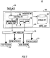
- Fig. 2 is a block diagram for explaining a control system of the assist instrument 10.
- the control unit 30 comprises a processing unit 60 and a storage unit 62.
- One example of the processing unit 60 is a CPU.
- the processing unit 60 functions as an acquiring unit 64, an attachment-removal control unit 66, and an assist control unit 68 by reading out an assist instrument process program stored in the storage unit 62.
- the acquiring unit 64 acquires an attachment-removal instruction from the input unit 28.
- the acquiring unit 64 outputs the acquired attachment-removal instruction to the attachment-removal control unit 66.
- the attachment-removal control unit 66 Upon acquisition of a first attachment-removal instruction, the attachment-removal control unit 66 judges that is a time of putting on or taking off, including a time of putting on or taking off of the pants portion 12. The attachment-removal control unit 66, when having judged that it is a time of putting on or taking off, controls the power supply unit 26, thereby controlling the first actuator 14, the second actuator 16, the third actuator 18, and the fourth actuator 20 to extend. Thereby, the attachment-removal control unit 66 extends the pants portion 12 in both the circumferential direction and the up-down direction.
- the circumferential direction herein means the direction along the circumferences of legs. Also, the up-down direction is one example of a direction that intersects the circumferential direction.
- the extension amount of the pants portion 12 is an amount of extension of the pants portion 12 as compared with a state where it is worn by the user.
- the extension amount of the pants portion 12 at a time of putting on or taking off is stored in the storage unit 62.
- the attachment-removal control unit 66 when having acquired an attachment-removal instruction, extends the pants portion 12 based on the extension amount stored in the storage unit 62.
- a plurality of extension amounts may be stored in the storage unit 62 in association with a plurality of users.
- the input unit 28 may identify a user by fingerprint authentication or the like.
- the attachment-removal control unit 66 Upon acquisition of a second attachment-removal instruction, the attachment-removal control unit 66 controls the power supply unit 26 to stop voltage application to the first actuator 14, the second actuator 16, the third actuator 18, and the fourth actuator 20. Also, the attachment-removal control unit 66 outputs an assist instruction to the assist control unit 68.
- the attachment-removal control unit 66 Upon acquisition of an attachment-removal instruction after outputting the assist instruction, the attachment-removal control unit 66 outputs an assist stop instruction to the assist control unit 68. After outputting the assist stop instruction, the attachment-removal control unit 66 controls the power supply unit 26 to control voltage applied to the first actuator 14, the second actuator 16, the third actuator 18, and the fourth actuator 20 to extend them. Thereby, the attachment-removal control unit 66 extends the pants portion 12 in both the circumferential direction and the longitudinal direction.
- the attachment-removal control unit 66 controls the power supply unit 26 to stop voltage application to the first actuator 14, the second actuator 16, the third actuator 18, and the fourth actuator 20.
- the assist control unit 68 controls the power supply unit 26 to control voltage applied to the first actuator 14, the second actuator 16, the third actuator 18, and the fourth actuator 20 to assist walking or running of the user.
- the assist control unit 68 controls the power supply unit 26 to stop voltage application to the first actuator 14, the second actuator 16, the third actuator 18, and the fourth actuator 20.
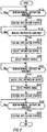
- Fig. 3 is a flowchart of an assist instrument process performed by the assist instrument 10.
- the assist instrument process is performed by the processing unit 60 reading out an assist instrument program stored in the storage unit 62.
- the attachment-removal control unit 66 judges whether an attachment-removal instruction has been acquired (S10).
- the attachment-removal control unit 66 is in a standby state until the attachment-removal control unit 66 acquires an attachment-removal instruction via the acquiring unit 64 (S10: No).
- the attachment-removal control unit 66 controls the power supply unit 26 to apply voltage to the first actuator 14, the second actuator 16, the third actuator 18, and the fourth actuator 20 (S12).
- the pants portion 12 extends in the circumferential direction and the longitudinal direction. The user wears the extended pants portion 12, together with the first actuator 14, the second actuator 16, the third actuator 18, and the fourth actuator 20.
- the attachment-removal control unit 66 acquires the attachment-removal instruction from the input unit 28 via the acquiring unit 64 (S14: Yes). Thereby, the attachment-removal control unit 66 controls the power supply unit 26 to stop voltage application to the first actuator 14, the second actuator 16, the third actuator 18, and the fourth actuator 20 (S16). Next, the attachment-removal control unit 66 outputs an assist instruction to the assist control unit 68 (SI8).
- the assist control unit 68 Upon acquisition of the assist instruction, the assist control unit 68 starts an assist process (S20). In the assist process, the assist control unit 68 controls the power supply unit 26 to control voltage applied to the first actuator 14, the second actuator 16, the third actuator 18, and the fourth actuator 20 separately. Thereby, the first actuator 14, the second actuator 16, the third actuator 18, and the fourth actuator 20 assist raising and lowering of the legs of the user to support walking and running.
- the assist control unit 68 controls voltage applied to the first actuator 14 and the second actuator 16 via the power supply unit 26 to contract the first actuator 14 and the second actuator 16.
- a method of contraction may be realized by stopping voltage application, or may be realized by lowering applied voltage.
- the assist control unit 68 controls voltage applied to the first actuator 14 and the second actuator 16 via the power supply unit 26 to extend the first actuator 14 and the second actuator 16.
- the assist control unit 68 controls extension and contraction of the third actuator 18 and the fourth actuator 20 via the power supply unit 26.
- the assist control unit 68 controls voltage application based on voltage values and time intervals predetermined and stored in the storage unit 62.
- the assist control unit 68 controls voltage applied to the first actuator 14 and the fourth actuator 20 via the power supply unit 26 to contract the first actuator 14 and the fourth actuator 20. Also, when the user moves leftward, the assist control unit 68 controls voltage applied to the second actuator 16 and the third actuator 18 via the power supply unit 26 to contract the second actuator 16 and the third actuator 18.
- the assist control unit 68 continues the assist process.
- the attachment-removal control unit 66 Upon acquisition of an attachment-removal instruction via the acquiring unit 64 (S22: Yes), the attachment-removal control unit 66 outputs an assist stop instruction to the assist control unit 68 (S24). Thereby, the assist control unit 68 ends the assist process (S26).
- the attachment-removal control unit 66 controls the power supply unit 26 to start voltage application to the first actuator 14, the second actuator 16, the third actuator 18, and the fourth actuator 20 (S28). Thereby, the pants portion 12 extends in the circumferential direction and the longitudinal direction.
- the attachment-removal control unit 66 continues voltage application and is in a standby state until an attachment-removal instruction is acquired (S30: No).
- the attachment-removal control unit 66 controls the power supply unit 26 to stop voltage application to the first actuator 14, the second actuator 16, the third actuator 18, and the fourth actuator 20 (S32).
- the attachment-removal control unit 66 may terminate its operation in a state that the pants portion 12 is contracted, or terminate its operation in a state that the pants portion 12 is extended. Thereby, the assist instrument process ends.
- the attachment-removal control unit 66 extends the first actuator 14, the second actuator 16, the third actuator 18, and the fourth actuator 20, thereby extending the pants portion 12. Thereby, the user can put on or take off the pants portion 12 easily.
- Fig. 4 is a front view of an assist instrument 110 to which sub extension-contraction parts are provided.
- the assist instrument 110 further comprises a first sub extension-contraction part 70, a second sub extension-contraction part 72, a third sub extension-contraction part 74, and a fourth sub extension-contraction part 76.
- the pants portion 12 that is one example of a clothing member to be worn and removed on and from the body of the user, the first sub extension-contraction part 70, the second sub extension-contraction part 72, the third sub extension-contraction part 74, and the fourth sub extension-contraction part 76 are one example of an attachment-removal member.
- the first sub extension-contraction part 70 is provided to the pants portion 12 at a portion that corresponds to an upper portion of the right leg.
- the second sub extension-contraction part 72 is provided to the pants portion 12 at a portion that corresponds to an upper portion of the left leg.
- the first sub extension-contraction part 70 and the second sub extension-contraction part 72 are formed in a rectangular shape along the up-down direction.
- the third sub extension-contraction part 74 is provided to the pants portion 12 at a portion that corresponds to a lower portion of the right leg.
- the fourth sub extension-contraction part 76 is provided to the pants portion 12 that corresponds to a lower portion of the left leg.
- the third sub extension-contraction part 74 and the fourth sub extension-contraction part 76 are formed in a rectangular shape along the horizontal direction.
- the attachment-removal control unit 66 controls the first sub extension-contraction part 70, the second sub extension-contraction part 72, the third sub extension-contraction part 74, and the fourth sub extension-contraction part 76 by applying voltage to them, at a time of at least one of putting on and taking off of the pants portion 12.
- the first sub extension-contraction part 70 and the second sub extension-contraction part 72 extend in the up-down direction to extend, in the longitudinal direction, the pants portion 12 in a contracted state as indicated at the right leg portion in Fig. 4 .
- the third sub extension-contraction part 74 and the fourth sub extension-contraction part 76 extend in the horizontal direction to extend, in the circumferential direction, the pants portion 12 in a contracted state as indicated at the right leg portion in Fig. 4 . Thereby, the user can put on or take off the pants portion 12 easily.
- Fig. 4 the example shown in Fig.
- the attachment-removal control unit 66 may extend the pants portion 12 by controlling the first actuator 14, the second actuator 16, the third actuator 18, and the fourth actuator 20, in addition to by controlling the first sub extension-contraction part 70, the second sub extension-contraction part 72, the third sub extension-contraction part 74, and the fourth sub extension-contraction part 76.
- Fig. 5 is a front view of an assist instrument 210 worn by a user.
- the assist instrument 210 comprises a shirt portion 212, a first actuator 214, a second actuator 216, a third actuator 218, the wire 22, the housing part 24, the power supply unit 26, the input unit 28, and the control unit 30.
- the shirt portion 212 is one example of an attachment-removal member.
- the shirt portion 212 has a shirt-like shape through which the upper arm of the right arm, the upper arm of the left arm, and the upper body can be inserted.
- the shirt portion 212 is made of extendable and contractable chemical fibers or the like.
- the shirt portion 212 surrounds the upper body of the user to constrict the upper body of the user by certain constraining force. Thereby, the shirt portion 212, in a worn state, is fixed to the upper body of the user.
- the first actuator 214 is provided to the shirt portion 212 from the right shoulder of the user to the right portion of the back surface of the waist.
- the second actuator 216 is provided to the shirt portion 212 from the left shoulder of the user to the left portion of the back surface of the waist.
- the third actuator 218 is provided to the shirt portion 212 at an upper portion of the back of the user so as to extend in the horizontal direction.
- the attachment-removal control unit 66 controls the power supply unit 26 to apply voltage to the first actuator 214, the second actuator 216, and the third actuator 218 to extend them.
- the first actuator 214 and the second actuator 216 extend along approximately the up-down direction.
- the shirt portion 212 extends in the longitudinal direction.
- the third actuator 218 extends in the horizontal direction.
- the shirt portion 212 extends in the circumferential direction. As a result, the user can put on the shirt portion 212 easily.
- the assist instrument 210 When assisting the muscular strength of the user, the assist instrument 210 extends and contracts the first actuator 214 and the second actuator 216. Thereby, the user can lift baggage and the like placed on the floor easily. Also, the assist instrument 210 can correct the posture of the user by contracting the third actuator 218.
- Fig. 6 is a front view of an assist instrument 310 worn by the user.
- the assist instrument 310 comprises a pants portion 312, a first elastic member 314, a second elastic member 316, a first sub extension-contraction part 370, a second sub extension-contraction part 372, a third sub extension-contraction part 374, the wire 22, the housing part 24, the power supply unit 26, the input unit 28, and the control unit 30.
- the first elastic member 314 is provided from the upper right to the lower left of the front surface of the pants portion 312 that covers the thigh of the right leg.
- the second elastic member 316 is provided from the upper left to the lower right of the front surface of the pants portion 12 that covers the thigh of the left leg. The first elastic member 314 and the second elastic member 316, in a state that the pants portion 312 is worn by the user, exerts the elastic force on the legs of the user so as to raise the legs.
- the first sub extension-contraction part 370 is provided on the front surface of the pants portion 312 that covers the waist.
- the first sub extension-contraction part 370 extends in the horizontal direction.
- the second sub extension-contraction part 372 is provided to the front surface of the pants portion 312 that covers a lower portion of the thigh of the right leg.
- the second sub extension-contraction part 372 extends in the horizontal direction.
- the third sub extension-contraction part 374 is provided to the front surface of the pants portion 312 that covers a lower portion of the thigh of the left leg.
- the third sub extension-contraction part 374 extends in the horizontal direction.
- the attachment-removal control unit 66 extends the first sub extension-contraction part 370, the second sub extension-contraction part 372, and the third sub extension-contraction part 374. Thereby, because the pants portion 312 extends in the circumferential direction, the user can put on the pants portion 312 easily.
- Figs. 1 to 6 showed examples in which the assist units are the first actuator 14, the second actuator 16, the third actuator 18, and the fourth actuator 20 that are controlled to extend or contract electrically by the control unit 30, instead of this, for example, an assist unit that has an elastic body like rubber, and is not electrically controlled may be used.
- an assist unit that has an elastic body like rubber, and is not electrically controlled may be used.
- the attachment-removal control unit 66 by extending, by the attachment-removal control unit 66, the first sub extension-contraction part 70, the second sub extension-contraction part 72, the third sub extension-contraction part 74, and the fourth sub extension-contraction part 76 respectively, the pants portion 312 is extended.
- the respective extension amounts of the first sub extension-contraction part 70, the second sub extension-contraction part 72, the third sub extension-contraction part 74, and the fourth sub extension-contraction part 76 are set to amounts that cause formation of space between the pants portion 312 and the body of the user that is sufficient for the user to remove the pants portion 312, and the extending force is set to force that causes extension not only of the pants portion 312 but also of the assist units.
- the assist units have both an elastic body and an actuator that is electrically controlled to extend or contract like the first actuator 14, the second actuator 16, the third actuator 18, and the fourth actuator 20, the pants portion 312 may be extended by extending the actuator by the attachment-removal control unit 66 at a time of putting on or taking off of the pants portion 312.
- the extending force of the actuator is set to force that causes extension of the attachment-removal member and the elastic body respectively.
- Fig. 7 is a front view of an assist instrument 410 worn by a user.
- the assist instrument 410 comprises a first actuator 414, a second actuator 416, the wire 22, the housing part 24, the power supply unit 26, the input unit 28, and the control unit 30.
- the first actuator 414 is attached wearably and removably to the right leg of the user.
- the first actuator 414 is, when it is worn, attached by being wound around the right leg of the user multiple times.
- the second actuator 416 is attached wearably and removably to the left leg of the user.
- the second actuator 416 is, when it is worn, attached by being wound around the left leg of the user.
- the attachment-removal control unit 66 Upon receiving an input by the user via the input unit 28, indicating that it is a time of putting on or taking off, the attachment-removal control unit 66 controls the first actuator 414 and the second actuator 416 at a time of at least one of putting on and taking off to extend the first actuator 414 and the second actuator 416.
- the assist instrument has a detecting unit that detects an extension-contraction state of the pants portion 12 to output the length of the extended pants portion 12 as an extension-contraction value.
- the detecting unit is a pressure sensor.
- each of the above-mentioned actuator may share the detecting unit. Upon receiving external force, the above-mentioned actuators generate electromotive force. The detecting unit shared by the actuators detects, based on this electromotive force, an extension-contraction value that is one example of an extension-contraction state of the pants portion 12.
- the attachment-removal control unit 66 compares an extension-contraction value acquired from the detecting unit and an extension-contraction threshold stored in the storage unit 62. If the extension-contraction value is equal to or higher than the extension-contraction threshold, the detecting unit judges that it is a time of putting on or taking off when the user put on or takes off the pants portion 12 to output an attachment-removal instruction to the attachment-removal control unit 66.
- An example of a case where the detecting unit judges that it is a time of putting on or taking off is when the user pulls rubber of the waist portion of the pants portion 12 by a predetermined length or longer. Thereby, the attachment-removal control unit 66 extends the actuators to extend the pants portion 12.
- an extension amount is stored in the storage unit 62, and each actuator is extended and contracted at a time of putting on or taking off based on the extension amount
- the attachment-removal control unit 66 may calculate the extension amount and the contraction amount.
- the attachment-removal control unit 66 may calculate the extension amount and the contraction amount at a time of putting on or taking off of the pants portion 12 or the like based on physical information of the user stored in the storage unit 62 to extend or contract the pants portion 12.
- the attachment-removal control unit 66 may calculate physical information based on the image of the user captured by the image-capturing unit.
- Each actuator may be a type that extends due to voltage application, or may be a type that contracts due to voltage application, and extends by the maximum amount when voltage is not applied.
- an attachment-removal member is extended by extension of the actuators, by stopping voltage application when detaching the attachment-removal member.
- the extension amount of the actuators is set so that the extension amount of the attachment-removal member becomes larger when voltage is not applied than the extension amount at a time of putting on,
- actuators such as the first actuator 14 are extended at times of both putting on and taking off of an attachment-removal member such as the pants portion 12
- the actuators may be extended at a time of at least one of putting on and taking off of the attachment-removal member.
- an actuator may be provided to a pants portion having a size larger than the body of the user, for example, larger than the thickness of a leg, and the actuator may be contracted so that the pants portion contacts the body by controlling the actuator and a sub extension-contraction part after the pants portion is put on.
- the contraction amount of the pants portion as input by a wearing instruction may be set in advance according to the size of the body of the user, or a detecting unit to detect the contraction amount may be provided, and the contraction amount may be set based on its detection result.
- the detecting unit it is detected whether the contraction amount is a contraction amount with which the assist function of the assist instrument functions appropriately.
Landscapes
- Health & Medical Sciences (AREA)
- General Health & Medical Sciences (AREA)
- Public Health (AREA)
- Pain & Pain Management (AREA)
- Physical Education & Sports Medicine (AREA)
- Rehabilitation Therapy (AREA)
- Life Sciences & Earth Sciences (AREA)
- Animal Behavior & Ethology (AREA)
- Veterinary Medicine (AREA)
- Epidemiology (AREA)
- Engineering & Computer Science (AREA)
- Orthopedic Medicine & Surgery (AREA)
- Textile Engineering (AREA)
- Biomedical Technology (AREA)
- Neurology (AREA)
- Manipulator (AREA)
- Rehabilitation Tools (AREA)
- Prostheses (AREA)
- Professional, Industrial, Or Sporting Protective Garments (AREA)
Claims (14)
- Unterstützungsinstrument (10, 110, 210, 310, 410) mit:einem Anbring-/Entfernungselement (12, 212, 312), das an einem Körper eines Benutzers tragbar und entfernbar platziert werden kann;einer Hilfseinheit (14, 16, 18, 20, 70, 72, 74, 76, 214, 216, 218, 314, 316, 370, 372, 374, 414, 416), die an dem Anbring-/Entfernungselement (12, 212, 312) vorgesehen ist und eine Muskelstärke durch einen Verlängerungs- und/oder Kontraktionsvorgang des Anbring-/Entfernungselements unterstützt; undeiner Steuerungseinheit (30), die einen Vorgang der Einheit (14, 16, 18, 20, 70, 72, 74, 76, 214, 216, 218, 314, 316, 370, 372, 374, 414, 416) steuert;dadurch gekennzeichnet, dass die Steuerungseinheit (30) eingerichtet ist, umden Vorgang der Hilfseinheit (14, 16, 18, 20, 70, 72, 74, 76, 214, 216, 218, 314, 316, 370, 372, 374, 414, 416) zu einem Zeitpunkt eines Anlegens und/oder Ablegens des Anbring-/Entfernungselements (12, 212, 312) um die Hilfseinheit (14, 16, 18, 20, 70, 72, 74, 76, 214, 216, 218, 314, 316, 370, 372, 374, 414, 416) zu steuern, um dadurch das Anbring-/Entfernungselement (12, 212, 312) zu verlängern.
- Unterstützungsinstrument (10, 110, 210, 310, 410) nach Anspruch 1, bei dem die Hilfseinheit (14, 16, 18, 20, 70, 72, 74, 76, 214, 216, 218, 314, 316, 370, 372, 374, 414, 416) ein Aktuator (14, 16, 18, 20, 214, 216, 218, 414, 416) einschließlich eines Polymermaterials ist, das sich aufgrund einer Stromversorgung verlängert oder kontrahiert.
- Unterstützungsinstrument (10, 110, 210, 310, 410) nach Anspruch 2, bei dem die Hilfseinheit (14, 16, 18, 20, 70, 72, 74, 76, 214, 216, 218, 314, 316, 370, 372, 374, 414, 416) einen elastischen Körper aufweist und eine Verlängerungskraft der Hilfseinheit (14, 16, 18, 20, 70, 72, 74, 76, 214, 216, 218, 314, 316, 370, 372, 374, 414, 416) das Anbring-/Entfernungselement (12, 212, 312) und den elastischen Körper jeweils verlängert.
- Unterstützungsinstrument (10, 110, 210, 310, 410) nach einem der Ansprüche 1 bis 3, bei dem
die Steuerungseinheit (30) den Verlängerungs-Kontraktions-Teil zu einem Zeitpunkt eines Anlegens und/oder Ablegens des Anbring-/Entfernungselements (12, 212, 312) steuert, um den Verlängerungs-Kontraktions-Teil zu verlängern, wodurch das Anbring-/Entfernungselement (12, 212, 312) verlängert wird. - Unterstützungsinstrument (10, 110, 210, 310, 410) nach Anspruch 4, bei dem die Steuerungseinheit (30) den Verlängerungs-Kontraktions-Teil nach dem Anlegen des Anbring-Entfernung-Elements (12, 212, 312) steuert, um das Anbring-/Entfernungselement (12, 212, 312) zu kontrahieren, sodass das Anbring-/Entfernungselement (12, 212, 312) den Körper des Benutzers berührt.
- Unterstützungsinstrument (10, 110, 210, 310, 410) nach einem der Ansprüche 1 bis 5, bei dem die Steuerungseinheit (30) eingerichtet ist, den Vorgang der Unterstützungseinheit (14, 16, 18, 20, 70, 72, 74, 76, 214, 216, 218, 314, 316, 370, 372, 374, 414, 416) nach dem Anlegen des Anbring-/Entfernungselements (12, 212, 312) zu steuern, um das Anbring-/Entfernungselement (12, 212, 312) so zu kontrahieren, dass das Anbring-/Entfernungselement (12, 212, 312) den Körper des Benutzers berührt.
- Unterstützungsinstrument (10, 110, 210, 310, 410) nach einem der Ansprüche 1 bis 6, bei dem
das Anbring-/Entfernungselement (12, 212, 312) tragbar und/oder entfernbar an dem Körper des Benutzers befestigt ist und verlängerbar und kontrollierbar ist; und
ferner mit einer Eingabeeinheit (28), die einen Anbring-/Entfernungs-Befehl eingibt, der ein Anlegen oder Ablegen des Anbring-/Entfernungselements (12, 212, 312) angibt, wobei
die Steuerungseinheit (30) das Anbring-/Entfernungselement (12, 212, 312) durch erhalten des Anbring-/Entfernungs-Befehls verlängert. - Unterstützungsinstrument (10, 110, 210, 310, 410) nach einem der Ansprüche 1 bis 7, bei dem
das Anbring-/Entfernungselement (12, 212, 312) an dem Körper des Benutzers tragbar und entfernbar befestigt ist und verlängerbar und kontrollierbar ist; und
ferner mit einer Erfassungseinheit, die einen Verlängerungs-Kontraktions-Zustand des Anbring-/Entfernungselements (12, 212, 312) erfasst, wobei
die Steuerungseinheit (30) das Anbring-/Entfernungselement (12, 212, 312) basierend auf den durch die Erfassungseinrichtung erfassten Verlängerungs-Kontraktions-Zustand verlängert. - Unterstützungsinstrument (10, 110, 210, 310, 410) nach einem der Ansprüche 1 bis 8, bei dem das Anbring-/Entfernungselement (12, 212, 312) an dem Körper des Benutzers tragbar und entfernbar befestigt ist und verlängerbar und kontrollierbar ist, wobei
das Anbring-/Entfernungselement (12, 212, 312) einen Teil des Körpers des Benutzers umgibt, und
die Steuerungseinheit (30) das Anbring-/Entfernungselement (12, 212, 312) in einer Umfangsrichtung zu einem Zeitpunkt eines Anlegens oder Ablegens verlängert. - Unterstützungsinstrument (10, 110, 210, 310, 410) nach einem der Ansprüche 1 bis 9, bei dem
das Anbring-/Entfernungselement (12, 212, 312) an dem Körper des Benutzers tragbar und entfernbar befestigt ist und verlängerbar und kontrollierbar ist; wobei
das Anbring-/Entfernungselement (12, 212, 312) einen Teil des Körpers des Benutzers umgibt, und
die Steuerungseinheit (30) das Anbring-/Entfernungselement (12, 212, 312) in einer Richtung verlängert, um eine Umfangsrichtung zu schneiden, in welcher das Anbring-/Entfernungselement (12, 212, 312) den Teil des Körpers von dem Benutzer umgibt. - Unterstützungsinstrument (10, 110, 210, 310, 410) nach einem der Ansprüche 1 bis 10, bei dem
das Anbring-/Entfernungselement (12, 212, 312) an dem Körper des Benutzers tragbar und entfernbar befestigt ist und verlängerbar und kontrollierbar ist; wobei
die Steuerungseinheit (30) das Anbring-/Entfernungselement (12, 212, 312) verglichen mit einem Zustand verlängert, in dem das Anbring-/Entfernungselement (12, 212, 312) an den Körper des Benutzers getragen wird. - Unterstützungsinstrument (10, 110, 210, 310, 410) nach einem der Ansprüche 1 bis 11, bei dem das Anbring-/Entfernungselement (12, 212, 312) an dem Körper des Benutzers tragbar und entfernbar befestigt ist und verlängerbar und kontrollierbar ist, wobei
die Steuerungseinheit (30) das Anbring-/Entfernungselement (12, 212, 312) basierend auf einem Verlängerungs-Kontraktions-Betrag des Anbring-/Entfernungselements (12, 212, 312) zu einem Zeitpunkt eines Anlegens oder Ablegens verlängert und kontrahiert. - Unterstützungsinstrument (10, 110, 210, 310, 410) nach einem der Ansprüche 1 bis 12, bei dem das Anbring-/Entfernungselement (12, 212, 312) an dem Körper des Benutzers tragbar und entfernbar befestigt ist und verlängerbar und kontrollierbar ist, wobei
die Steuerungseinheit (30) das Anbring-/Entfernungs Element (12, 212, 312) basierend auf einem Verlängerungs-Kontraktions-Betrag des Anbring-/Entfernungselements (12, 212, 312) zu einem Zeitpunkt eines Anlegens oder Ablegens verlängert und kontrahiert, wobei der Verlängerungs-Kontraktions-Betrag durch eine physische Information des Benutzers berechnet wird. - Unterstützungsinstrument (10, 110, 210, 310, 410) nach Anspruch 13, bei dem die Steuerungseinheit (30) die physische Information des Benutzers von einem aufgenommenen Bild des Benutzers berechnet.
Applications Claiming Priority (2)
| Application Number | Priority Date | Filing Date | Title |
|---|---|---|---|
| JP2012231387 | 2012-10-19 | ||
| PCT/JP2013/006193 WO2014061282A1 (ja) | 2012-10-19 | 2013-10-18 | 補助用具 |
Publications (3)
| Publication Number | Publication Date |
|---|---|
| EP2910228A1 EP2910228A1 (de) | 2015-08-26 |
| EP2910228A4 EP2910228A4 (de) | 2016-04-20 |
| EP2910228B1 true EP2910228B1 (de) | 2018-08-08 |
Family
ID=50487861
Family Applications (1)
| Application Number | Title | Priority Date | Filing Date |
|---|---|---|---|
| EP13846590.1A Active EP2910228B1 (de) | 2012-10-19 | 2013-10-18 | Hilfsvorrichtung |
Country Status (5)
| Country | Link |
|---|---|
| US (1) | US10548797B2 (de) |
| EP (1) | EP2910228B1 (de) |
| JP (1) | JP6229660B2 (de) |
| CN (1) | CN104736121B (de) |
| WO (1) | WO2014061282A1 (de) |
Families Citing this family (6)
| Publication number | Priority date | Publication date | Assignee | Title |
|---|---|---|---|---|
| CN105902363B (zh) * | 2015-02-19 | 2020-02-07 | 松下知识产权经营株式会社 | 辅助服、辅助服的控制部的控制方法 |
| CN105902367B (zh) * | 2015-02-19 | 2020-02-07 | 松下知识产权经营株式会社 | 辅助服、辅助服的控制部的控制方法 |
| JP6449713B2 (ja) * | 2015-04-23 | 2019-01-09 | 本田技研工業株式会社 | 動作補助装置 |
| JP6832530B2 (ja) * | 2016-09-30 | 2021-02-24 | パナソニックIpマネジメント株式会社 | アシストシステム、アシスト方法及びコンピュータプログラム |
| JP7065369B2 (ja) * | 2017-10-13 | 2022-05-12 | パナソニックIpマネジメント株式会社 | アシスト装置、アシスト装置の作動方法及びプログラム |
| US10836029B2 (en) * | 2017-11-28 | 2020-11-17 | Seismic Holdings, Inc. | Exosuit load bearing distribution systems |
Family Cites Families (10)
| Publication number | Priority date | Publication date | Assignee | Title |
|---|---|---|---|---|
| US5201074A (en) * | 1991-06-10 | 1993-04-13 | Dicker Timothy P | Exercise suit with resilient reinforcing |
| JP4000254B2 (ja) | 2001-11-22 | 2007-10-31 | 株式会社ワコール | 腰部負担軽減具 |
| SG103371A1 (en) * | 2001-12-28 | 2004-04-29 | Matsushita Electric Works Ltd | Wearable human motion applicator |
| JP4424269B2 (ja) * | 2005-06-24 | 2010-03-03 | カシオ計算機株式会社 | 筋力制御装置 |
| JP4345025B2 (ja) * | 2006-09-12 | 2009-10-14 | 国立大学法人 北海道大学 | 筋力補助装置 |
| JP2010051416A (ja) * | 2008-08-27 | 2010-03-11 | Nabtesco Corp | 足関節の動作補助装置および足関節の動作補助装置の制御方法 |
| US20110166491A1 (en) * | 2008-09-10 | 2011-07-07 | University Of Tsukuba | Biological signal measuring wearing device and wearable motion assisting apparatus |
| WO2010028504A1 (en) * | 2008-09-15 | 2010-03-18 | Simon Fraser University | Variable volume garments |
| US8769712B2 (en) * | 2010-03-25 | 2014-07-08 | Massachusetts Institute Of Technology | Gravity-loading body suit |
| JP5868011B2 (ja) * | 2011-03-16 | 2016-02-24 | 国立大学法人九州大学 | 歩行運動補助具 |
-
2013
- 2013-10-18 CN CN201380054502.6A patent/CN104736121B/zh active Active
- 2013-10-18 JP JP2014541957A patent/JP6229660B2/ja active Active
- 2013-10-18 WO PCT/JP2013/006193 patent/WO2014061282A1/ja not_active Ceased
- 2013-10-18 EP EP13846590.1A patent/EP2910228B1/de active Active
-
2015
- 2015-04-17 US US14/689,560 patent/US10548797B2/en active Active
Non-Patent Citations (1)
| Title |
|---|
| None * |
Also Published As
| Publication number | Publication date |
|---|---|
| JP6229660B2 (ja) | 2017-11-15 |
| WO2014061282A1 (ja) | 2014-04-24 |
| US10548797B2 (en) | 2020-02-04 |
| CN104736121B (zh) | 2017-05-17 |
| EP2910228A1 (de) | 2015-08-26 |
| JPWO2014061282A1 (ja) | 2016-09-05 |
| US20150216756A1 (en) | 2015-08-06 |
| EP2910228A4 (de) | 2016-04-20 |
| CN104736121A (zh) | 2015-06-24 |
Similar Documents
| Publication | Publication Date | Title |
|---|---|---|
| US10548797B2 (en) | Assist instrument | |
| JP6489422B2 (ja) | アシストウェア、アシストウェアの作動方法、及び、制御プログラム | |
| CN102724943B (zh) | 行走辅助装置 | |
| JP4487060B2 (ja) | 装着式動作補助装置、装着式動作補助装置の制御方法および制御用プログラム | |
| EP2910229A1 (de) | Vorrichtung zur unterstützung der muskelkraft | |
| CN102149318B (zh) | 生物体信号测量穿戴用具和穿戴式动作辅助装置 | |
| KR101703634B1 (ko) | 편마비 환자를 위한 보행훈련 장치 | |
| JP2014087636A (ja) | 歩行支援装置 | |
| WO2014034145A1 (ja) | 補助用具 | |
| KR102459982B1 (ko) | 배터리들의 충전 상태에 기초하여 배터리들을 전자 장치들로 연결하는 배터리 관리 장치 및 방법 | |
| JP2014133121A (ja) | 補助用具 | |
| JP2014079329A (ja) | 着用型筋力検出具、制御装置および筋力検出システム | |
| JP6094209B2 (ja) | 動作補助装置及び動作補助制御用プログラム | |
| JP6587452B2 (ja) | マッサージ装置 | |
| KR20190083057A (ko) | 걸음걸이 진단 및 치료용 스마트 깔창 | |
| JP6592497B2 (ja) | 動作補助装置及び加圧装置 | |
| JP2018114278A (ja) | 歩行転倒防止装置、歩行転倒防止装置の制御装置及び制御方法、並びに、歩行転倒防止装置用制御プログラム | |
| JP5882696B2 (ja) | 動作補助装置及び動作補助制御用プログラム | |
| Li et al. | Development of a lightweight walking assist wear using PVC gel artificial muscles | |
| KR102482763B1 (ko) | 전기활성반응 슈트 및 전기활성반응 슈트를 이용하여 근력 지원하는 기능성 전기자극반응 방법 | |
| KR102497495B1 (ko) | 사용자의 움직임에 따라 발목의 2축 강성을 보조하는 발목 보조 장치 | |
| US20250152109A1 (en) | Posture control device | |
| US20200146627A1 (en) | A Bra for Measuring a Physiological Signal | |
| CN113730212B (zh) | 按摩机 | |
| KR101897066B1 (ko) | 환자 관리 시스템 |
Legal Events
| Date | Code | Title | Description |
|---|---|---|---|
| PUAI | Public reference made under article 153(3) epc to a published international application that has entered the european phase |
Free format text: ORIGINAL CODE: 0009012 |
|
| 17P | Request for examination filed |
Effective date: 20150515 |
|
| AK | Designated contracting states |
Kind code of ref document: A1 Designated state(s): AL AT BE BG CH CY CZ DE DK EE ES FI FR GB GR HR HU IE IS IT LI LT LU LV MC MK MT NL NO PL PT RO RS SE SI SK SM TR |
|
| AX | Request for extension of the european patent |
Extension state: BA ME |
|
| RAP1 | Party data changed (applicant data changed or rights of an application transferred) |
Owner name: NIKON CORPORATION |
|
| DAX | Request for extension of the european patent (deleted) | ||
| RA4 | Supplementary search report drawn up and despatched (corrected) |
Effective date: 20160322 |
|
| RIC1 | Information provided on ipc code assigned before grant |
Ipc: A41D 1/00 20060101ALN20160316BHEP Ipc: A61H 3/00 20060101AFI20160316BHEP Ipc: A61H 1/02 20060101ALI20160316BHEP Ipc: B25J 11/00 20060101ALI20160316BHEP |
|
| 17Q | First examination report despatched |
Effective date: 20170508 |
|
| GRAP | Despatch of communication of intention to grant a patent |
Free format text: ORIGINAL CODE: EPIDOSNIGR1 |
|
| RIC1 | Information provided on ipc code assigned before grant |
Ipc: A61H 1/02 20060101ALI20180122BHEP Ipc: B25J 11/00 20060101ALI20180122BHEP Ipc: A41D 1/00 20180101ALN20180122BHEP Ipc: A61H 3/00 20060101AFI20180122BHEP |
|
| INTG | Intention to grant announced |
Effective date: 20180301 |
|
| GRAS | Grant fee paid |
Free format text: ORIGINAL CODE: EPIDOSNIGR3 |
|
| GRAA | (expected) grant |
Free format text: ORIGINAL CODE: 0009210 |
|
| AK | Designated contracting states |
Kind code of ref document: B1 Designated state(s): AL AT BE BG CH CY CZ DE DK EE ES FI FR GB GR HR HU IE IS IT LI LT LU LV MC MK MT NL NO PL PT RO RS SE SI SK SM TR |
|
| REG | Reference to a national code |
Ref country code: GB Ref legal event code: FG4D |
|
| REG | Reference to a national code |
Ref country code: CH Ref legal event code: EP Ref country code: AT Ref legal event code: REF Ref document number: 1026144 Country of ref document: AT Kind code of ref document: T Effective date: 20180815 |
|
| REG | Reference to a national code |
Ref country code: IE Ref legal event code: FG4D |
|
| REG | Reference to a national code |
Ref country code: DE Ref legal event code: R096 Ref document number: 602013041824 Country of ref document: DE |
|
| REG | Reference to a national code |
Ref country code: FR Ref legal event code: PLFP Year of fee payment: 6 |
|
| REG | Reference to a national code |
Ref country code: NL Ref legal event code: MP Effective date: 20180808 |
|
| REG | Reference to a national code |
Ref country code: LT Ref legal event code: MG4D |
|
| REG | Reference to a national code |
Ref country code: AT Ref legal event code: MK05 Ref document number: 1026144 Country of ref document: AT Kind code of ref document: T Effective date: 20180808 |
|
| PG25 | Lapsed in a contracting state [announced via postgrant information from national office to epo] |
Ref country code: PL Free format text: LAPSE BECAUSE OF FAILURE TO SUBMIT A TRANSLATION OF THE DESCRIPTION OR TO PAY THE FEE WITHIN THE PRESCRIBED TIME-LIMIT Effective date: 20180808 Ref country code: LT Free format text: LAPSE BECAUSE OF FAILURE TO SUBMIT A TRANSLATION OF THE DESCRIPTION OR TO PAY THE FEE WITHIN THE PRESCRIBED TIME-LIMIT Effective date: 20180808 Ref country code: BG Free format text: LAPSE BECAUSE OF FAILURE TO SUBMIT A TRANSLATION OF THE DESCRIPTION OR TO PAY THE FEE WITHIN THE PRESCRIBED TIME-LIMIT Effective date: 20181108 Ref country code: SE Free format text: LAPSE BECAUSE OF FAILURE TO SUBMIT A TRANSLATION OF THE DESCRIPTION OR TO PAY THE FEE WITHIN THE PRESCRIBED TIME-LIMIT Effective date: 20180808 Ref country code: AT Free format text: LAPSE BECAUSE OF FAILURE TO SUBMIT A TRANSLATION OF THE DESCRIPTION OR TO PAY THE FEE WITHIN THE PRESCRIBED TIME-LIMIT Effective date: 20180808 Ref country code: NO Free format text: LAPSE BECAUSE OF FAILURE TO SUBMIT A TRANSLATION OF THE DESCRIPTION OR TO PAY THE FEE WITHIN THE PRESCRIBED TIME-LIMIT Effective date: 20181108 Ref country code: NL Free format text: LAPSE BECAUSE OF FAILURE TO SUBMIT A TRANSLATION OF THE DESCRIPTION OR TO PAY THE FEE WITHIN THE PRESCRIBED TIME-LIMIT Effective date: 20180808 Ref country code: IS Free format text: LAPSE BECAUSE OF FAILURE TO SUBMIT A TRANSLATION OF THE DESCRIPTION OR TO PAY THE FEE WITHIN THE PRESCRIBED TIME-LIMIT Effective date: 20181208 Ref country code: FI Free format text: LAPSE BECAUSE OF FAILURE TO SUBMIT A TRANSLATION OF THE DESCRIPTION OR TO PAY THE FEE WITHIN THE PRESCRIBED TIME-LIMIT Effective date: 20180808 Ref country code: RS Free format text: LAPSE BECAUSE OF FAILURE TO SUBMIT A TRANSLATION OF THE DESCRIPTION OR TO PAY THE FEE WITHIN THE PRESCRIBED TIME-LIMIT Effective date: 20180808 Ref country code: GR Free format text: LAPSE BECAUSE OF FAILURE TO SUBMIT A TRANSLATION OF THE DESCRIPTION OR TO PAY THE FEE WITHIN THE PRESCRIBED TIME-LIMIT Effective date: 20181109 |
|
| PG25 | Lapsed in a contracting state [announced via postgrant information from national office to epo] |
Ref country code: HR Free format text: LAPSE BECAUSE OF FAILURE TO SUBMIT A TRANSLATION OF THE DESCRIPTION OR TO PAY THE FEE WITHIN THE PRESCRIBED TIME-LIMIT Effective date: 20180808 Ref country code: AL Free format text: LAPSE BECAUSE OF FAILURE TO SUBMIT A TRANSLATION OF THE DESCRIPTION OR TO PAY THE FEE WITHIN THE PRESCRIBED TIME-LIMIT Effective date: 20180808 Ref country code: LV Free format text: LAPSE BECAUSE OF FAILURE TO SUBMIT A TRANSLATION OF THE DESCRIPTION OR TO PAY THE FEE WITHIN THE PRESCRIBED TIME-LIMIT Effective date: 20180808 |
|
| PG25 | Lapsed in a contracting state [announced via postgrant information from national office to epo] |
Ref country code: ES Free format text: LAPSE BECAUSE OF FAILURE TO SUBMIT A TRANSLATION OF THE DESCRIPTION OR TO PAY THE FEE WITHIN THE PRESCRIBED TIME-LIMIT Effective date: 20180808 Ref country code: EE Free format text: LAPSE BECAUSE OF FAILURE TO SUBMIT A TRANSLATION OF THE DESCRIPTION OR TO PAY THE FEE WITHIN THE PRESCRIBED TIME-LIMIT Effective date: 20180808 Ref country code: IT Free format text: LAPSE BECAUSE OF FAILURE TO SUBMIT A TRANSLATION OF THE DESCRIPTION OR TO PAY THE FEE WITHIN THE PRESCRIBED TIME-LIMIT Effective date: 20180808 Ref country code: RO Free format text: LAPSE BECAUSE OF FAILURE TO SUBMIT A TRANSLATION OF THE DESCRIPTION OR TO PAY THE FEE WITHIN THE PRESCRIBED TIME-LIMIT Effective date: 20180808 Ref country code: CZ Free format text: LAPSE BECAUSE OF FAILURE TO SUBMIT A TRANSLATION OF THE DESCRIPTION OR TO PAY THE FEE WITHIN THE PRESCRIBED TIME-LIMIT Effective date: 20180808 |
|
| REG | Reference to a national code |
Ref country code: DE Ref legal event code: R097 Ref document number: 602013041824 Country of ref document: DE |
|
| PG25 | Lapsed in a contracting state [announced via postgrant information from national office to epo] |
Ref country code: SK Free format text: LAPSE BECAUSE OF FAILURE TO SUBMIT A TRANSLATION OF THE DESCRIPTION OR TO PAY THE FEE WITHIN THE PRESCRIBED TIME-LIMIT Effective date: 20180808 Ref country code: SM Free format text: LAPSE BECAUSE OF FAILURE TO SUBMIT A TRANSLATION OF THE DESCRIPTION OR TO PAY THE FEE WITHIN THE PRESCRIBED TIME-LIMIT Effective date: 20180808 Ref country code: DK Free format text: LAPSE BECAUSE OF FAILURE TO SUBMIT A TRANSLATION OF THE DESCRIPTION OR TO PAY THE FEE WITHIN THE PRESCRIBED TIME-LIMIT Effective date: 20180808 |
|
| REG | Reference to a national code |
Ref country code: CH Ref legal event code: PL |
|
| PLBE | No opposition filed within time limit |
Free format text: ORIGINAL CODE: 0009261 |
|
| STAA | Information on the status of an ep patent application or granted ep patent |
Free format text: STATUS: NO OPPOSITION FILED WITHIN TIME LIMIT |
|
| REG | Reference to a national code |
Ref country code: BE Ref legal event code: MM Effective date: 20181031 |
|
| PG25 | Lapsed in a contracting state [announced via postgrant information from national office to epo] |
Ref country code: LU Free format text: LAPSE BECAUSE OF NON-PAYMENT OF DUE FEES Effective date: 20181018 Ref country code: MC Free format text: LAPSE BECAUSE OF FAILURE TO SUBMIT A TRANSLATION OF THE DESCRIPTION OR TO PAY THE FEE WITHIN THE PRESCRIBED TIME-LIMIT Effective date: 20180808 |
|
| 26N | No opposition filed |
Effective date: 20190509 |
|
| REG | Reference to a national code |
Ref country code: IE Ref legal event code: MM4A |
|
| PG25 | Lapsed in a contracting state [announced via postgrant information from national office to epo] |
Ref country code: CH Free format text: LAPSE BECAUSE OF NON-PAYMENT OF DUE FEES Effective date: 20181031 Ref country code: BE Free format text: LAPSE BECAUSE OF NON-PAYMENT OF DUE FEES Effective date: 20181031 Ref country code: LI Free format text: LAPSE BECAUSE OF NON-PAYMENT OF DUE FEES Effective date: 20181031 Ref country code: SI Free format text: LAPSE BECAUSE OF FAILURE TO SUBMIT A TRANSLATION OF THE DESCRIPTION OR TO PAY THE FEE WITHIN THE PRESCRIBED TIME-LIMIT Effective date: 20180808 |
|
| PG25 | Lapsed in a contracting state [announced via postgrant information from national office to epo] |
Ref country code: IE Free format text: LAPSE BECAUSE OF NON-PAYMENT OF DUE FEES Effective date: 20181018 |
|
| PG25 | Lapsed in a contracting state [announced via postgrant information from national office to epo] |
Ref country code: MT Free format text: LAPSE BECAUSE OF NON-PAYMENT OF DUE FEES Effective date: 20181018 |
|
| PG25 | Lapsed in a contracting state [announced via postgrant information from national office to epo] |
Ref country code: TR Free format text: LAPSE BECAUSE OF FAILURE TO SUBMIT A TRANSLATION OF THE DESCRIPTION OR TO PAY THE FEE WITHIN THE PRESCRIBED TIME-LIMIT Effective date: 20180808 |
|
| PG25 | Lapsed in a contracting state [announced via postgrant information from national office to epo] |
Ref country code: PT Free format text: LAPSE BECAUSE OF FAILURE TO SUBMIT A TRANSLATION OF THE DESCRIPTION OR TO PAY THE FEE WITHIN THE PRESCRIBED TIME-LIMIT Effective date: 20180808 |
|
| PG25 | Lapsed in a contracting state [announced via postgrant information from national office to epo] |
Ref country code: MK Free format text: LAPSE BECAUSE OF NON-PAYMENT OF DUE FEES Effective date: 20180808 Ref country code: HU Free format text: LAPSE BECAUSE OF FAILURE TO SUBMIT A TRANSLATION OF THE DESCRIPTION OR TO PAY THE FEE WITHIN THE PRESCRIBED TIME-LIMIT; INVALID AB INITIO Effective date: 20131018 Ref country code: CY Free format text: LAPSE BECAUSE OF FAILURE TO SUBMIT A TRANSLATION OF THE DESCRIPTION OR TO PAY THE FEE WITHIN THE PRESCRIBED TIME-LIMIT Effective date: 20180808 |
|
| P01 | Opt-out of the competence of the unified patent court (upc) registered |
Effective date: 20230517 |
|
| PGFP | Annual fee paid to national office [announced via postgrant information from national office to epo] |
Ref country code: GB Payment date: 20250828 Year of fee payment: 13 |
|
| PGFP | Annual fee paid to national office [announced via postgrant information from national office to epo] |
Ref country code: FR Payment date: 20250908 Year of fee payment: 13 |
|
| PGFP | Annual fee paid to national office [announced via postgrant information from national office to epo] |
Ref country code: DE Payment date: 20250902 Year of fee payment: 13 |