EP2910311B1 - Schaumpumpe mit mehreren Luftkammern - Google Patents
Schaumpumpe mit mehreren Luftkammern Download PDFInfo
- Publication number
- EP2910311B1 EP2910311B1 EP15153074.8A EP15153074A EP2910311B1 EP 2910311 B1 EP2910311 B1 EP 2910311B1 EP 15153074 A EP15153074 A EP 15153074A EP 2910311 B1 EP2910311 B1 EP 2910311B1
- Authority
- EP
- European Patent Office
- Prior art keywords
- piston
- air
- chamber
- outer air
- liquid
- Prior art date
- Legal status (The legal status is an assumption and is not a legal conclusion. Google has not performed a legal analysis and makes no representation as to the accuracy of the status listed.)
- Active
Links
Images




Classifications
-
- B—PERFORMING OPERATIONS; TRANSPORTING
- B05—SPRAYING OR ATOMISING IN GENERAL; APPLYING FLUENT MATERIALS TO SURFACES, IN GENERAL
- B05B—SPRAYING APPARATUS; ATOMISING APPARATUS; NOZZLES
- B05B11/00—Single-unit hand-held apparatus in which flow of contents is produced by the muscular force of the operator at the moment of use
- B05B11/01—Single-unit hand-held apparatus in which flow of contents is produced by the muscular force of the operator at the moment of use characterised by the means producing the flow
- B05B11/10—Pump arrangements for transferring the contents from the container to a pump chamber by a sucking effect and forcing the contents out through the dispensing nozzle
- B05B11/1087—Combination of liquid and air pumps
-
- A—HUMAN NECESSITIES
- A47—FURNITURE; DOMESTIC ARTICLES OR APPLIANCES; COFFEE MILLS; SPICE MILLS; SUCTION CLEANERS IN GENERAL
- A47K—SANITARY EQUIPMENT; ACCESSORIES THEREFOR, e.g. TOILET ACCESSORIES
- A47K5/00—Holders or dispensers for soap, toothpaste or the like
- A47K5/14—Foam or lather making devices
-
- B—PERFORMING OPERATIONS; TRANSPORTING
- B05—SPRAYING OR ATOMISING IN GENERAL; APPLYING FLUENT MATERIALS TO SURFACES, IN GENERAL
- B05B—SPRAYING APPARATUS; ATOMISING APPARATUS; NOZZLES
- B05B11/00—Single-unit hand-held apparatus in which flow of contents is produced by the muscular force of the operator at the moment of use
- B05B11/01—Single-unit hand-held apparatus in which flow of contents is produced by the muscular force of the operator at the moment of use characterised by the means producing the flow
- B05B11/10—Pump arrangements for transferring the contents from the container to a pump chamber by a sucking effect and forcing the contents out through the dispensing nozzle
- B05B11/1001—Piston pumps
-
- B—PERFORMING OPERATIONS; TRANSPORTING
- B05—SPRAYING OR ATOMISING IN GENERAL; APPLYING FLUENT MATERIALS TO SURFACES, IN GENERAL
- B05B—SPRAYING APPARATUS; ATOMISING APPARATUS; NOZZLES
- B05B7/00—Spraying apparatus for discharge of liquids or other fluent materials from two or more sources, e.g. of liquid and air, of powder and gas
- B05B7/02—Spray pistols; Apparatus for discharge
- B05B7/04—Spray pistols; Apparatus for discharge with arrangements for mixing liquids or other fluent materials before discharge
- B05B7/0416—Spray pistols; Apparatus for discharge with arrangements for mixing liquids or other fluent materials before discharge with arrangements for mixing one gas and one liquid
- B05B7/0491—Spray pistols; Apparatus for discharge with arrangements for mixing liquids or other fluent materials before discharge with arrangements for mixing one gas and one liquid the liquid and the gas being mixed at least twice along the flow path of the liquid
-
- B—PERFORMING OPERATIONS; TRANSPORTING
- B05—SPRAYING OR ATOMISING IN GENERAL; APPLYING FLUENT MATERIALS TO SURFACES, IN GENERAL
- B05B—SPRAYING APPARATUS; ATOMISING APPARATUS; NOZZLES
- B05B11/00—Single-unit hand-held apparatus in which flow of contents is produced by the muscular force of the operator at the moment of use
- B05B11/01—Single-unit hand-held apparatus in which flow of contents is produced by the muscular force of the operator at the moment of use characterised by the means producing the flow
- B05B11/10—Pump arrangements for transferring the contents from the container to a pump chamber by a sucking effect and forcing the contents out through the dispensing nozzle
- B05B11/1042—Components or details
- B05B11/1066—Pump inlet valves
- B05B11/1067—Pump inlet valves actuated by pressure
- B05B11/1069—Pump inlet valves actuated by pressure the valve being made of a resiliently deformable material or being urged in a closed position by a spring
-
- B—PERFORMING OPERATIONS; TRANSPORTING
- B05—SPRAYING OR ATOMISING IN GENERAL; APPLYING FLUENT MATERIALS TO SURFACES, IN GENERAL
- B05B—SPRAYING APPARATUS; ATOMISING APPARATUS; NOZZLES
- B05B11/00—Single-unit hand-held apparatus in which flow of contents is produced by the muscular force of the operator at the moment of use
- B05B11/01—Single-unit hand-held apparatus in which flow of contents is produced by the muscular force of the operator at the moment of use characterised by the means producing the flow
- B05B11/10—Pump arrangements for transferring the contents from the container to a pump chamber by a sucking effect and forcing the contents out through the dispensing nozzle
- B05B11/1042—Components or details
- B05B11/1073—Springs
- B05B11/1074—Springs located outside pump chambers
-
- B—PERFORMING OPERATIONS; TRANSPORTING
- B05—SPRAYING OR ATOMISING IN GENERAL; APPLYING FLUENT MATERIALS TO SURFACES, IN GENERAL
- B05B—SPRAYING APPARATUS; ATOMISING APPARATUS; NOZZLES
- B05B7/00—Spraying apparatus for discharge of liquids or other fluent materials from two or more sources, e.g. of liquid and air, of powder and gas
- B05B7/0018—Spraying apparatus for discharge of liquids or other fluent materials from two or more sources, e.g. of liquid and air, of powder and gas with devices for making foam
- B05B7/0025—Spraying apparatus for discharge of liquids or other fluent materials from two or more sources, e.g. of liquid and air, of powder and gas with devices for making foam with a compressed gas supply
- B05B7/0031—Spraying apparatus for discharge of liquids or other fluent materials from two or more sources, e.g. of liquid and air, of powder and gas with devices for making foam with a compressed gas supply with disturbing means promoting mixing, e.g. balls, crowns
- B05B7/0037—Spraying apparatus for discharge of liquids or other fluent materials from two or more sources, e.g. of liquid and air, of powder and gas with devices for making foam with a compressed gas supply with disturbing means promoting mixing, e.g. balls, crowns including sieves, porous members or the like
Definitions
- This invention relates to foam pumps for dispensing liquid mixed with air as a foam and, more particularly, to a piston pump with multiple axially spaced air pumps.
- Liquid piston pumps for dispensing liquid through a countertop from a reservoir disposed below the countertop are known in which the body of the pump is inserted through an opening in the countertop into a reservoir, with merely an actuator and discharge outlet above the countertop. These liquid pumps are operative in a single stroke as to allow the production of a desired unit dosage volume of liquid.
- the opening through the countertop is selected to be as small as possible, for example, 7/8 inch in diameter, to provide a pleasing appearance.
- Foam piston pumps are known for simultaneously dispensing a liquid mixed with air as in a foam.
- One such foaming pump is disclosed, for example, in U.S. Patent 7,337,930 to Ophardt et al, issued March 4, 2008 , which discloses a piston pump according to the preamble of claim 1.
- foam piston pumps suffer the disadvantage that the pumps typically cannot be inserted through a relatively small opening into a reservoir and have a reasonable stroke length while allowing an adequate volume of air to be displaced as to allow the production of a desired unit dosage volume of foamed liquid product in a single stroke.
- the present inventor has also appreciated the disadvantage that with known foam piston pumps, as the diameter of the opening through which the pump is to be inserted reduces, then the stroke length required to dispense a desired volume of air increases.
- the present invention provides an improved foam piston pump in which a multiple of air pumps are disposed coaxially about a piston member and spaced axially along the piston member.
- the present invention provides a piston pump according to claim 1.
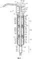
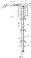
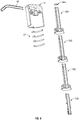
- FIG. 1 illustrates a dispenser 10 incorporating a pump 12 in accordance with the first embodiment of the present invention.
- the dispenser 10 includes a reservoir 13 containing a fluid 14.
- the reservoir 13 has a cylindrical upwardly opening neck 15 and the pump 12 extends downwardly through the neck 15 into the reservoir 13 and is operative to dispense fluid 14 from the reservoir out a discharge outlet 17 on the pump 12.
- the reservoir 13 is fixedly secured to a countertop 16 with the neck 15 extending upwardly through an opening 18 through the countertop 16 and being engaged by a threaded collar 19 to secure the reservoir 13 to the countertop 16 underneath the countertop 16.
- the pump 12 is vertically slidable within the neck 15 for removal and replacement.
- the reservoir 13 may be replenished with the fluid 14 by a user pouring fluid downwardly into the reservoir 13 through the neck 15.
- This arrangement is useful, for example, in a kitchen or washroom, to provide for dispensing of foamed cleaning fluid by use of the pump 12 above the top of countertop 16 from the reservoir 13 permanently secured below the countertop 16, yet with substantial portions of the pump 12 disposed below the countertop 16.
- the pump 12 comprises a piston chamber-forming member 20, a spring 21 and a piston-forming element 22.
- the piston chamber-forming member 20 extends longitudinally about a central axis 23 from a lower end 24 to an upper end 25.
- the piston chamber-forming member 20 defines a central chamber 26 therein coaxially about the axis 23 and within an annular chamber wall 27.
- the piston chamber-forming member 20 has a liquid inlet 28 at the lower end 24 in communication with the liquid 14 in the reservoir 13.
- a hollow dip tube 29 is coupled to the lower end 24 of the piston chamber-forming member 20 by which the liquid inlet 28 is in communication with fluid 14 in the reservoir 13.
- the first upper casing assembly 200 is identical to the second upper casing assembly 300 and each may be considered to be an identical modular component, which is advantageous but not necessary as each may be different.
- the lower casing 101 extends from the lower end 24 to an upper end 105 and defines therein a liquid chamber 106 and coaxially above the liquid chamber 106 a lower air chamber 107.
- the lower casing 101 has a wall 108 with a cylindrical first lower portion 109 and a cylindrical second lower portion 110.
- the liquid chamber 106 is defined within the cylindrical first lower portion 109 of the wall 108.
- the lower air chamber 107 is defined within the cylindrical second lower portion 110 of the wall 108.
- the liquid chamber 106 has a diameter which is less than the diameter of the lower air chamber 107.
- the wall 108 includes a radially inwardly extending shoulder 111 which forms a lower end 112 of the lower air chamber 107.
- the liquid chamber 106 opens at an upper end 113 through the shoulder 111 coaxially into the lower air chamber 107.
- the wall 108 extends inwardly as a shoulder 114 at a lower end 115 of the liquid chamber 106.
- An opening 116 through the shoulder 114 at the lower end 115 of the liquid chamber 106 opens via a passageway 117 to the lower end 24.
- the one-way valve 102 is secured in a friction-fit relation within the opening 116 at the lower end 115 of the liquid chamber 106.
- the one-way valve 102 has a fluted stem 118 and a resilient annular disc 119 extending radially outwardly from the stem 118 at the upper end of the one-way valve 102.
- the stem 118 carries axially extended flutes permitting fluid flow axially past the stem 118 when the one-way valve 102 is snap-fitted within the opening 116.
- the disc 119 is resilient and biased such that under its inherent bias a circumferential edge of the disc 119 engages the shoulder 114 to prevent fluid flow downwardly from the liquid chamber 106 to the reservoir 13.
- the disc 119 is deflectable such that when the pressure in the liquid chamber 106 is less than the pressure in the reservoir 13 fluid will flow upwardly past the disc 119 from the reservoir 13 into the liquid chamber 106.
- the wall 108 of the lower casing 101 at its upper end 105 defines an inwardly directed annular catch shoulder 125 with an annular surface directed at least in part axially downwardly.
- the first upper casing 201 has a lower end 204 and an upper end 205.
- the first upper casing 201 has a wall 208 with a cylindrical upper portion 210 defining a first upper air chamber 207 therein.
- the wall 208 includes a radially inwardly extending annular upper shoulder 211 which forms a lower end 212 of the first upper air chamber 207.
- An opening 216 extends through the upper shoulder 211.
- the wall 208 also includes a radially inwardly extending annular lower shoulder 220.
- An opening 221 extends through the lower shoulder 220.
- the wall 208 defines between the upper shoulder 211 and the lower shoulder 220 an annular recess 223.
- the opening 216 through the upper shoulder 111 has a diameter less than a diameter of the recess 223 and less than a diameter of the opening 221 through the lower shoulder 220 such that the seal disc 203 which is resilient may be forced downwardly into the recess 223 past the shoulder 214 to be received within the recess 223 against removal.
- the first upper casing 201 has an opening 224 at its upper end 205.
- the wall 208 of the first upper casing 201 at its upper end 205 defines an inwardly directed annular catch shoulder 225 with an annular surface directed at least in part axially downwardly.
- the wall 208 of the first upper casing 201 carries about its lower end 204 a radially outwardly extending catching shoulder 226 with an annular surface directed at least in part axially upwardly.
- the upper end 105 of the lower casing 101 is adapted to engage the lower end 204 of the first upper casing 201 in a snap-fit relation with the catch shoulder 125 of the lower casing 101 to engage the catching shoulder 226 of the first upper casing 201 to resist disengagement.
- the second upper casing 301 has a wall 308 with a cylindrical upper portion 310 defining a second upper air chamber 307 therein.
- the wall 308 includes a radially inwardly extending annular upper shoulder 311 which forms a lower end 312 of the second upper air chamber 307.
- An opening 316 extends through the upper shoulder 311.
- the wall 308 also includes a radially inwardly extending annular lower shoulder 320.
- An opening 321 extends through the lower shoulder 320.
- the wall 308 defines between the upper shoulder 311 and the lower shoulder 320 an annular recess 323.
- the opening 316 through the upper shoulder 311 has a diameter less than the diameter of the recess 323 and less than a diameter of the opening 321 through the lower shoulder 320 such that the seal disc 303 which is resilient may be forced downwardly into the recess 323 past the shoulder 314 to be received within the recess 323 against removal.
- the wall 308 of the second upper casing 301 at its upper end 305 defines an inwardly directed annular catch shoulder 325 with an annular surface directed at least in part axially downwardly.
- the wall 308 of the second upper casing 301 carries about the opening 324 at its lower end 304 a radially outwardly extending catching shoulder 326 with an annular surface directed at least in part axially upwardly.
- the upper end 205 of the upper air casing 201 is adapted to engage the lower end 304 of the second upper casing 301 in a snap-fit relation with the catch shoulder 225 of the first upper casing 201 to engage the catching shoulder 326 of the second upper casing 301 to resist disengagement.
- the housing 31 comprises a generally cylindrical outer tube 401 extending coaxially about the axis 23.
- the outer tube 401 has a lower end 404 and an upper end 405. Proximate the upper end 405 of the outer tube 401, an annular flange 406 extends radially inwardly from the outer tube 401.
- the annular flange 406 the supports a cylindrical inner tube 407 which extends coaxial with the outer tube 401 about the axis 23.
- the inner tube 407 has a lower end 408 and an upper end 409.
- the lower end 408 of the inner tube 407 carries a radially outwardly extending catching shoulder 426 with an annular surface directed at least in part axially upwardly.
- the upper end 305 of the second upper air casing 301 is adapted to engage the lower end 408 of the inner tube 407 in a snap-fit relation with the catch shoulder 325 of the second upper casing 301 to engage the catching shoulder 426 of the inner tube 407 of the housing to resist disengagement.
- the first annular seal disc 203 comprises a radially outermost annular ring 230 from which an annular sealing flange 231 extends radially inwardly to an annular distal end 232.
- the annular sealing flange 231 extends from the ring 230 radially inwardly and axially upwardly to the distal end 232.
- the second annular seal disc 303 comprises a radially outermost annular ring 330 from which an annular sealing flange 331 extends radially inwardly to an annular distal end 332.
- the annular sealing flange 331 extends from the ring 330 radially inwardly and axially upwardly to the distal end 332.
- the lower casing 101 is secured in a friction-fit relation to the first upper casing 201 which is secured in a friction-fit relation to the second upper casing 301 which is secured in a friction-fit relation to the housing 31.
- the one-way valve 102 is secured in a friction-fit relation to the lower casing 101.
- the first annular seal disc 203 is snap-fitted into the recess 223 of the first upper casing 201.
- the second annular seal disc 303 is secured in a friction-fit relation into the recess 323 of the second upper casing 301.
- the annular chamber wall 27 includes the wall 108, the wall 208 and the wall 308.
- the central chamber 26 includes, axially inline one above the other, the liquid chamber 106, the lower air chamber 107, the first upper air chamber 207 and the second upper air chamber 307 in axial communication with each other via the openings 113, 221, 216, 321 and 316.
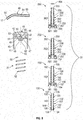
- the piston-forming element 22 includes a liquid piston 130, a lower air piston 150, a first upper air piston 250, a second upper air piston 350, a foam producing member 464, a head 41 and an outlet tube 40.
- each of the lower air piston 150 and the first upper air piston 250 is identical and each may be considered to be an identical modular component, which is advantageous but not necessary as each may be different.
- the second upper air piston 350 is identical to the lower air piston 150 with the exception that there is no equivalent on the second upper air piston 350 to the air port 162.
- the second air piston 350 may be identical to the lower air piston 150 with the second air piston 350 having an air port, not shown, identical to the air port 162 provided that the head 41 engages the second air piston 350 in a manner to sealably close the air port on the second air piston 350.
- the lower air piston 150 has an elongate tubular stem 151 with a tubular wall 152.
- the stem 151 of the lower air piston 150 has a lower end 154 and an upper end 155.
- the tubular wall 152 defines a central passageway 153 longitudinally therethrough from the lower end 154 to the upper end 155 open at each end.
- the lower air piston 150 carries a first lower air sealing disc 156 which extends radially outwardly and axially downwardly from the stem 151 to an annular distal edge 157.
- a radially outwardly directed surface 158 of the wall 152 of the stem 151 carries a radially outwardly extending catching shoulder 159 with an annular surface directed, at least in part, axially downwardly.
- the stem 151 carries a socket 160 with a radially inwardly extending catch shoulder 161 with an annular surface directed, at least in part, axially upwardly.
- a first upper air port 162 is provided on the stem 151 and extends radially through the wall 152 of the stem 151 into the passageway 153. The first upper air port 162 is on the stem 151 above the lower air sealing disc 156.
- first upper air ports 162 are provided at diametrically opposed positions on the stem 151, however, only one is necessary.
- the radially outwardly directed surface 158 of the wall 152 of the stem 151 is cylindrical over a cylindrical portion 163 between the first lower air sealing disc 156 and the upper end 155.
- the first upper air piston 250 has an elongate tubular stem 251 with a tubular wall 252.
- the stem 251 of the first upper air piston 250 has a lower end 254 and an upper end 255.
- the tubular wall 252 defines a central passageway 253 longitudinally therethrough from the lower end 254 to the upper end 255 open at each end.
- the first upper air piston 250 carries a first upper air sealing disc 256 which extends radially outwardly and axially downwardly from the stem 251 to an annular distal edge 257.
- a radially outwardly directed surface 258 of the wall 252 of the stem 251 carries a radially outwardly extending catching shoulder 259 with an annular surface directed at least in part axially downwardly.
- the stem 251 carries a socket 260 with radially inwardly extending catch shoulder 261 with an annular surface directed at least in part axially upwardly.
- a second upper air port 262 is provided on the stem 251 and extends radially through the wall 252 of the stem 251 into the passageway 253.
- the second upper air port 262 is on the stem 251 above the first upper air sealing disc 256.
- the radially outwardly directed surface 258 of the wall 252 of the stem 251 is cylindrical over a cylindrical portion 263 between the first upper air sealing disc 256 and the upper end 255.
- the second upper air piston 350 has an elongate tubular stem 351 with a tubular wall 352.
- the stem 351 of the second upper air piston 350 has a lower end 354 and an upper end 355.
- the tubular wall 352 defines a central passageway 353 longitudinally therethrough from the lower end 354 to the upper end 355 open at each end.
- the second upper air piston 350 carries a second upper air sealing disc 356 which extends radially outwardly and axially downwardly from the stem 351 to an annular distal edge 357.
- a radially outwardly directed surface 358 of the wall 352 of the stem 351 carries a radially outwardly extending catching shoulder 359 with an annular surface directed at least in part axially downwardly.
- the stem 351 carries a socket 360 with radially inwardly extending catch shoulder 361 with an annular surface directed at least in part axially upwardly.
- the radially outwardly directed surface 358 of the wall 352 of the stem 351 is cylindrical over a cylindrical portion 363 between the second upper air sealing disc 356 and the upper end 355.
- the upper end 155 of the lower air piston 150 is adapted to be secured in a snap-fit relation against removal in the socket 260 of the first upper air piston 250 to secure the lower air piston 150 to the first upper air piston 250 with the catching shoulder 159 of the lower air piston 150 in opposition to the catch shoulder 261 of the socket 260 of the first upper air piston 250.
- the upper end 255 of the first upper air piston 250 is adapted to be secured in a snap-fit relation against removal in the socket 360 of the second upper air piston 350 to secure the first upper air piston 250 to the second upper air piston 350 with the catching surface 259 of the first upper air piston 250 in opposition to the catch shoulder 361 of the socket 360 of the second upper air piston 350.
- the liquid piston 130 has an elongate tubular stem 131 with a tubular wall 132.
- the stem 131 of the liquid piston 130 has a lower end 134 and an upper end 135.
- the tubular wall 132 defines a central passageway 133 longitudinally therethrough from the lower end 134 to the upper end 135.
- the passageway 133 is open at the upper end 135.
- the passageway 133 is closed at the lower end 134 by an end wall 136.
- a radially outwardly directed surface 137 of the wall 132 of the stem 131 carries a radially outwardly extending catching shoulder 138 with an annular surface directed, at least in part, axially downwardly.
- the upper end 135 of the liquid piston 130 is adapted to be secured in a snap-fit relation against removal in the socket 160 of the lower air piston 150 to secure the liquid piston 130 to the lower air piston 150 with the catching shoulder 138 of the liquid piston 130 in opposition to the catch shoulder 161 of the socket 160 of the lower air piston 150.
- the liquid piston 130 carries proximate its lower end 134, a radially outwardly extending liquid sealing disc 139.
- the lower liquid piston 130 carries proximate its lower end 134, a radially outwardly extending second lower air sealing disc 140 spaced axially upwardly from the liquid sealing disc 139.
- a liquid port 141 is provided on the stem 131 axially between the liquid sealing disc 139 and the second lower air sealing disc 140.
- the liquid port 141 extends radially through the wall 132 of the stem 131 into the passageway 131.
- a lower air port 142 is provided on the stem 131 above the lower air disc 142.
- the lower air port 142 extends radially through the wall 132 of the stem 131 into the passageway 131.
- the radially outwardly directed surface 137 of the wall 132 of the stem 131 is cylindrical.
- the head 41 comprises a top portion 42 from which an outer tube 43 extends about the axis 23 downwardly to an open lower end 44.
- the top portion 42 has an upper surface 46 and a lower surface 47.
- An inner tube 48 extends downwardly from the lower surface 47 coaxially about the axis 23 to an open lower end 62.
- a socket 49 is provided within the inner tube 48 having a catch shoulder 50 with an annular surface directed, at least in part, axially upwardly.
- a discharge passageway 51 is provided within the head 41 between an opening 52 coaxially within the socket 49 at an upper end of the socket 49 to an opening 53 directed forwardly.
- the outlet tube 40 is a hollow tube with a tube passageway 54 therethrough from a first end 55 to a second forward end 56 providing the discharge outlet 17.
- the outlet tube 40 is coupled to the top portion 42 with the first end 55 secured within the opening 53.
- a downwardly opening annular groove 57 is provided in the lower surface 47 coaxially between the outer tube 43 and the inner tube 48 with a blind upper end 58 to receive an upper end 59 of the spring 21.
- an upwardly opening annular groove 60 is provided coaxially between the outer tube 401 and the inner tube 407 with a blind upper end 61 on the annular flange 406 to receive a lower end 62 of the spring 21.
- a passageway 63 extends therethrough from the lower end 135 to the discharge outlet 17 including the central passageways 133, 153, 253 and 353, the socket 49, the discharge passageway 51 and the tube passageway 54.
- the assembled piston-forming element 22 has an elongate tubular stem 90 formed by the stems 131, 151, 251 and 351 with the central passageway 63 longitudinally therethrough including the passageways 133, 153, 253 and 353.
- the passageway 63 extends from a lower end 134 of the passageway 133 to an upper end 355 of the passageway 353.
- the upper end 355 of the second upper air piston 350 is adapted to be secured in a snap-fit relation against removal in the socket 49 of the head 41 to secure the second upper air piston 350 to the head 41 with the catching surface 359 of the second upper air piston 350 in opposition to the catch shoulder 50 of the socket 49 of the head 41.
- the foam producing member 464 is located within the socket 49 and sandwiched between the upper end of the socket 49 and the upper end 355 of the upper air piston 350 axially upwardly of the upper end 355.
- Air and liquid passing outwardly through the passageway 63 passes through the foam producing member 464 to create a foam of air and liquid as, for example, by creating turbulence in the fluids as they pass through the foam producing member 464.
- the foam producing member 464 may preferably comprise a screen member with suitably sized openings.
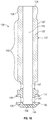
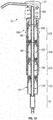
- Figures 1 and 2 show the assembled pump 12 in an extended position with the piston-forming element 22 engaged with the piston chamber-forming member 20.
- the spring 21 is in its inherent unbiased position.
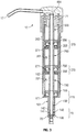
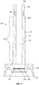
- a user manually applies downwardly directed forces to the upper surface 46 of the top portion 42 of the head 41 to axially compress the spring 21 against its inherent bias and move the piston-forming element 22 coaxially downwardly along the central axis 23 relative to the piston chamber-forming member 20 to the retracted position as shown in Figure 3 .
- the spring 21 has an inherent bias and from the retracted position of Figure 3 on release of the manual pressure, the spring 21 will move the piston-forming element 22 upwardly from the retracted position of Figure 3 to the extended position of Figure 2 .
- the outer tube 401 of the piston chamber-forming member has a radially outwardly extending annular flange 427 which, as seen in Figure 1 , engages the uppermost end of the neck 15 of the reservoir 13 to prevent downward movement of the piston chamber-forming member 20 relative to the countertop 16 and the reservoir 13.
- a cycle of operation arises in the relevant movement of the piston-forming element 22 from the extended position of Figure 2 to the retracted position of Figure 3 in a retraction stroke and then from the retracted position of Figure 3 to the extended position of Figure 2 in a withdrawal or extension stroke.
- the cylindrical portion 263 of the stem 251 of the first upper air piston 250 passes through the second annular seal disc 303 with the annular distal end 332 of the annular sealing flange 331 engaging the cylindrical portion 263 of the stem 251 to form a seal therewith preventing fluid flow therepast axially downwardly.
- the second upper air sealing disc 356 of the second upper air piston 350 engages the radially inwardly directed cylindrical surface of the cylindrical upper portion 310 of the second upper casing 301 forming a seal therewith to prevent fluid flow axially upwardly therepast.
- a second upper air pump 370 is thereby formed within the second upper casing 301 between the second upper casing assembly 300 and the piston forming element 22.
- the second upper air pump 370 provides a cylindrical second upper air compartment 371 radially in between the cylindrical upper portion 310 of the wall 308 of the second upper casing 301 and the stem 251 of the first upper air piston 250 and axially between the first upper air sealing disc 356 and the second annular seal disc 303.
- the second upper air port 262 provides communication between the second upper air compartment 371 and the passageway 253.
- the volume of the second upper air compartment 371 varies with relative movement of the piston-forming element 22 relative to the piston chamber-forming member 20 with the volume being largest in the extended position of Figure 2 and smallest in the retracted position of Figure 3 .
- a retraction stroke in moving from the extended position of Figure 2 to the retracted position of Figure 3 the volume of the second upper air compartment 371 decreases and fluid therein, typically substantially air, is compressed and forced out of the second upper air port 262 into the passageway 253 and hence out the discharge outlet 17.
- the volume of the second upper air compartment 371 increases and, fluid is drawn via the discharge outlet 17 into the passageway 253 and via the second upper air port 262 into the second upper air compartment 371.
- the first upper air sealing disc 256 of the first upper air piston 250 engages the radially inwardly directed cylindrical surface of the cylindrical upper portion 210 of the first upper casing 201 forming a seal therewith to prevent fluid flow axially upwardly therepast.
- a first upper air pump 270 is thereby formed within the first upper casing 201 between the first upper casing assembly 200 and the piston forming element 22.
- the first upper air pump 270 provides a cylindrical first upper air compartment 271 radially in between the cylindrical upper portion 210 of the wall 208 of the first upper casing 201 and the stem 151 of the lower air piston 150 and axially between the upper air sealing disc 256 and the first annular seal disc 203.
- the first upper air port 162 provides communication between the first upper air compartment 271 and the passageway 153.
- the volume of the first upper air compartment 271 varies with relative movement of the piston-forming element 22 relative to the piston chamber-forming member 20 with the volume being largest in the extended position of Figure 2 and smallest in the extended position of Figure 3 .
- a retraction stroke in moving from the extended position of Figure 2 to the retracted position of Figure 3 the volume of the first upper air compartment 271 increases and, fluid therein, typically substantially air, is compressed and forced out of the first upper air port 162 into the passageway 153 and hence out the discharge outlet 17.
- the volume of the second upper air compartment 271 increases and fluid is drawn via the discharge outlet 17 into the passageway 153 and via the first upper air port 162 into the first upper air compartment 271.
- the lower air sealing disc 156 of the lower air piston 150 extends radially outwardly to sealably engage with the radially inwardly directed surface of the wall 108 of the lower casing 101 in the cylindrical second lower portion 110 within the lower air chamber 107.
- the second lower air sealing disc 140 extends radially outwardly to sealably engage the wall 108 of the lower casing 101 in the cylindrical first lower portion 109 within the liquid chamber 106.
- a lower air pump 170 is defined within the lower casing 101 between the lower air piston 150 and the lower casing 101.
- the lower air pump 170 has an annular lower air compartment 171 which extends radially between the wall 108 of the lower casing 101 and the stem 151 of the lower air piston 150 and axially between the first lower air sealing disc 156 and the second lower air sealing disc 140.
- the lower air port 142 provides communication between the lower air compartment 171 and the central passageway 133.
- the lower air compartment 171 has a volume which varies as the piston-forming element 22 moved axially relative to the piston chamber-forming member 20.
- the lower air compartment 171 has a largest volume in the extended position of Figure 2 and a smallest volume in the retracted position of Figure 3 with this volume decreasing with movement of the piston-forming element 22 axially downwardly since the lower air compartment 171 is formed within a stepped chamber formed by the lower air chamber 107 and the lesser diameter liquid chamber 106.
- the liquid sealing disc 139 extends radially outwardly from the liquid piston 130 into engagement with the wall 108 of the lower casing 101 within the cylindrical first lower portion 109 of the liquid chamber 106.
- the liquid sealing disc 139 extends radially outwardly to a distal end 145.
- the liquid sealing disc 139 extends axially inwardly as it extends radially outwardly to the distal end 145 as seen in Figure 10 .
- the liquid sealing disc 139 is resilient adopting an unbiased inherent condition as seen in Figure 10 which preferably biases the distal end 143 of the liquid sealing disc 139 into the wall 108 of the cylindrical first lower portion 109 of the liquid chamber 106.
- the liquid sealing disc 139 can be deflected against this bias away from the wall 108 to permit fluid flow upwardly therepast.
- the lower air sealing disc 140 extends radially outwardly to a distal end 144 which engages the wall 108 of the lower casing 101 in the cylindrical first lower portion 109 forming the liquid chamber 106 and substantially prevents liquid flow axially upwardly past the lower air sealing disc 140.
- a liquid pump 70 is formed within the liquid chamber 106 between the stem 131 of the liquid piston 130 and the cylindrical first lower portion 109 of the lower casing 101 within the liquid chamber 106.
- the liquid pump 70 has a liquid compartment 71 defined within the liquid chamber 106 between one-way valve 102 and the lower end 134 of the liquid piston 130.
- the volume of the liquid compartment 71 varies with relative movement of the piston-forming element 22 within the piston chamber-forming member 20 with the volume being greatest in the extended position of Figure 2 and least in the retracted position of Figure 3 .
- the volume of the liquid compartment 71 reduces compressing liquid within the liquid compartment 71 closing the one-way valve 102 to fluid flow downwardly from the liquid compartment 71 and with the pressure in the liquid compartment 71 deflecting the liquid sealing disc 139 for liquid flow upwardly past the liquid sealing disc 139 into an annular compartment between the annular sealing disc 139 and the second lower air sealing disc 140 and via the liquid port 141 into the central passageway 133 in a retraction stroke.
- the volume of the liquid compartment 71 increases reducing the pressure within the liquid compartment 71 and drawing liquid from the reservoir past the one-way valve 102 into the liquid compartment 71.
- each of the liquid pump 70, the lower air pump 170, the first upper air pump 270 and the second upper air pump 370 are all in phase such that they, in a retraction stroke, simultaneously discharge fluid from their respective compartments and, in a retraction stroke, simultaneously draw fluid into their respective compartments.
- a unit dosage of liquid is discharged into the passageway 63 by the liquid pump 70 and, simultaneously, a volume of air is discharged from each of the air pumps 170, 270 and 370 so as to provide for the discharge of liquid and air simultaneously through the air forming member 464 forming foam which is discharged out the discharge outlet 17.
- fluid notably air
- the discharge outlet 17 through the passageway 63 and into each of the second upper air compartment 371, the first upper air compartment 271 and lower air compartment 171 simultaneously with fluid being drawn into the liquid compartment 71 from the reservoir.
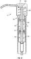
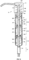
- FIG 12 illustrates a second embodiment of a pump 10 in accordance with the present invention which is identical to the pump of the first embodiment, however, with the exception that the second upper air pump 370 has been eliminated by elimination from the pump 10 of the first embodiment as seen in Figure 2 of the second upper casing assembly 300 and the first upper air piston 250.
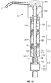
- FIG. 13 illustrates a third embodiment of a pump 10 in accordance with the present invention which is identical to the pump illustrated in Figure 2 , however, in which a third upper air pump 570 is provided by providing a third upper casing assembly 500 with a third upper casing 501 and a third upper air piston 550 which are modular and substantially the same as, respectively, the second upper casing assembly 300 and the first upper air piston 250.
- a feature of the invention is that the pumps are configured to be made from modular components.
- the first upper casing assembly 200 and the second upper casing assembly 300 are identical in their casings 201 and 301 and in their first and second upper annular seal disc 203 and 303.
- the lower air piston 150 and the first upper air piston 250 are identical.
- the second upper air piston 350 is identical to the lower air piston 150 with the exception that there is no equivalent on the second upper air piston 350 to the air port 162.
- the second air piston 350 can be identical to the lower air piston 150 by firstly providing the second air piston 350 with an air port, not shown, identical to the air port 162 and, secondly, providing the head 41 to engage the second air piston 350 in a manner to sealably close the air port on the second air piston 350, as can be accomplished by suitable modification of the socket 49 of the head 41.
- the use of modular components for the casing assembly and piston for air pumps permits pump arrangements with one, two or three identical upper air pumps to be assembled from modular components as is apparent from a comparison of the embodiments of Figures 2 , 12 and 13 . Each of these embodiments provided have a constant diameter exterior about the upper air pumps.
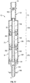
- Figure 14 illustrates a fourth embodiment of a piston pump 10 in accordance with the present invention which is identical to the piston pump as shown in Figure 2 but for two exceptions.
- a first exception is that while in Figure 2 the diameter of each of the central passageways 133, 153, 253 and 353 are identical and equal, in Figure 14 , the diameter of the passageway 63 changes varies between the lower end 134 and the upper end of the central passageway 353 of the second upper air pump 350, with the variation being an increase in diameter as the passageway 63 extends upwardly.
- a foam producing member 364 is provided within the socket 360 of the second upper air piston 350, a foam producing member 264 is provided within the socket 260 of the first upper air piston 250 and a foam producing member 164 is provided within the socket 160 of the lower air piston 150.
- liquid from the liquid pump 70 and air from the first air pump 170 are passed through the foam producing member 164 to produce at least some foam as a first resultant product which is joined from air from the first upper air pump 270 and passed through the foam producing member 264 forming a second resultant foamed product which, together with air from the second upper air pump 370, is passed first through the foam producing member 364 and then through the foam producing member 464 to produce a final resultant foam product which is delivered to the discharge outlet 17.
- the arrangement of Figure 14 with four foam producing members 164, 264, 364 and 464 provides for successive partial foaming of the air and fluid passing through each of the foam producing members. This is believed to be preferred for providing foam of desired characteristics.
- the increase in diameter and therefore the relative cross-sectional area of the passageway 66 axially upwardly can assist in adjusting the relative velocity of the fluid through the passageway 66 with a relative reduction in velocity compared to velocities which would arise in the arrangement in Figure 2 as the fluid extends axially upwardly.
- Figure 15 illustrates a fifth embodiment in accordance with the present invention which is identical to the embodiment of Figure 14 with the exception that the diameter and therefore the cross-sectional area of the passageway 133 increases axially upwardly and above the passageway 133, the passageway 63 decreases in diameter and, therefore, the cross-sectional area decreases axially upwardly successively through the central passageways 153, 253 and 353.
- Figure 16 illustrates a sixth embodiment of a foam pump in accordance with the present invention.
- the lower casing 101 has a liquid chamber 106 defined within a cylindrical second lower portion 109 and a cylindrical third lower portion 127 of a larger diameter than the cylindrical second lower portion 109.
- the liquid sealing disc 139 is within the enlarged diameter second lower portion 109 while the lower air sealing disc 140 is within the lesser diameter cylindrical lower portion 109.
- the volume of the liquid compartment 71 between the second lower air sealing disc 140 and the liquid sealing disc 139 increases to draw liquid in from the reservoir and, in the withdrawal stroke, the volume in the liquid compartment 71 decreases deflecting the second lower air sealing disc 140 radially inwardly and axially upwardly such that liquid flows upwardly past the second lower air sealing disc 140 into the lower air compartment 171.
- liquid and air within the lower air compartment 171 are urged in a retraction stroke into the passageway 63 for discharge out the discharge outlet 17.
- the liquid pump 70 is out of phase with the air pumps 170, 270 and 370 in the sense that in a retraction stroke, each of the air pumps is discharging fluid into the passageway 66 whereas the liquid pump 70 is drawing liquid into the liquid compartment 71 from the reservoir and, in a withdrawal stroke, the liquid pump 70 is discharging fluid into the lower air compartment 171 while each of the air pumps 170, 270 and 370 is drawing air from the atmosphere into their respective air compartments 171, 271 and 371.
- liquid pump 70 for use in various embodiments is not limited and the liquid pump 70 may have valves as illustrated in the embodiment of Figure 1 or a stepped chamber as illustrated in Figure 16 and may be in phase or out of phase with each of the air pumps. Each of the air pumps is shown to be coaxially aligned and operate in phase simultaneously.
- air which is drawn into each of the air pumps is atmospheric air drawn from the atmosphere via the discharge outlet 17. This is not necessary.
- Various arrangements may be provided for atmospheric air to enter the air compartments in a retraction stroke without passing through the discharge outlet.
- an arrangement for an air inlet valve could be provided as in the manner disclosed in U.S. Patent 7,337,930 to Ophardt et al, issued March 4, 2008 .
- Figures 1 to 16 illustrate arrangements which pump liquid upwardly from the reservoir 13, that is, from the lower end 24 of the piston chamber-forming member 20 upwardly.
- Figure 17 illustrates a seventh embodiment in which the pump 12 pumps liquid downwardly.
- similar reference numerals are used to identify equivalent elements in Figures 1 to 16 .
- the seventh embodiment of Figure 17 consists of an arrangement in which the pump 12 is the same as the pump 12 in the first embodiment of Figures 2 to 11 , but with the exceptions that pump 12 is inverted so that the end 24 of the piston chamber-forming member 20 is an upper end, both the head 41 and the tube 40 are eliminated, the air piston 350 is modified to provide the discharge outlet 17 at a lower end, and the air piston 350 is modified to carry an engagement flange 399 for engagement to slide the piston-forming element 22 relative the piston chamber-forming member 20.
- liquid from the reservoir is dispensed downwardly by the liquid pump 70 simultaneously with the air pumps 170, 270 and 370 discharging air to pass with the liquid downwardly through the foam producing member 436 and out the discharge outlet 17.
- the pump 12 of Figure 17 may have its housing 31 extend upwardly into a liquid containing reservoir, however, this is not necessary.
- many different configurations of the liquid pump 70 may be used in downwardly dispensing pumps in substitution of the liquid pump 70 shown. Downwardly dispensing liquid pumps are known as taught, for example, in U.S. Patent 5,165,577 to Ophardt, issued November 24, 1992 .
- the preferred embodiments illustrate the pumps 12 as being orientated with the central axis 23 vertical in each of the embodiments of Figures 1 to 17 . This is not necessary.
- the central axis 23 may be orientated to be horizontal or any angle between horizontal and vertical.
Landscapes
- Health & Medical Sciences (AREA)
- Public Health (AREA)
- Reciprocating Pumps (AREA)
- Containers And Packaging Bodies Having A Special Means To Remove Contents (AREA)
Claims (15)
- Kolbenpumpe, umfassen:ein kolbenkammerbildendes Element (20), welches sich in Längsrichtung um eine Achse (23) von einem inneren Ende (24) zu einem äußeren Ende (25) erstreckt;das kolbenkammerbildende Element (20) darin eine zentrale Kammer (26) koaxial um die Achse innerhalb einer ringförmigen Kammerwand (27) bildet;das kolbenkammerbildende Element einen Flüssigkeitseinlass (28) an dem inneren Ende in Verbindung mit einer Flüssigkeit (14) in einem Behälter (13) aufweist;ein kolbenbildendes Element (22), welches koaxial verschiebbar in der Kammer (26) in dem kolbenkammerbildenden Element (20) aufgenommen ist,das kolbenbildende Element (22) einen länglichen Rohrschaft (90) umfasst, mit einem zentralen Durchgang (63) in Längsrichtung dadurch, wobei sich der Durchgang (63) von einem inneren Ende (134) zu einem äußeren Ende erstreckt;das kolbenbildende Element (22) koaxial in dem kolbenkammerbildenden Element (20) zwischen einer ausgefahrenen Position und einer zurückgezogenen Position in einem Betriebszyklus, umfassend einen Rückwärtshub und einen Einfahrhub, gleitet, um die Flüssigkeit (14) aus dem Behälter (13) über den Flüssigkeitseinlass (28) zu saugen und die mit Luft vermischte Flüssigkeit durch das äußere Ende des Durchgangs (63) abzugeben;eine Flüssigkeitspumpe (70), gebildet zwischen dem kolbenkammerbildenden Element (20) und dem kolbenbildenden Element (22) in der Nähe des inneren Endes (134) des kolbenkammerbildenden Elements (22), wobei die Flüssigkeitspumpe (70) in dem Betriebszyklus wirksam ist, um die Flüssigkeit aus dem Behälter (13) über den Flüssigkeitseinlass (28) zu ziehen und die Flüssigkeit in den Durchgang (63) in der Nähe des inneren Endes (134) des Durchgangs (63) abzugeben;eine innere Luftpumpe (170), gebildet zwischen dem kolbenkammerbildenden Element (20) und dem kolbenbildenden Element (22) axial außerhalb der Flüssigkeitspumpe (70), die während des Betriebszyklus in einem Rückwärtshub wirksam ist, um Luft aus der Atmosphäre zu ziehen, und in einem Einfahrhub wirksam ist, um Luft in den Durchgang (63) durch eine innere Luftöffnung (142) abzugeben, welche sich radial nach innen durch den Schaft (90) in den Durchgang (63) erstreckt;wobei die Kolbenpumpe dadurch gekennzeichnet ist, dass sie des Weiteren umfasst:eine erste äußere Luftpumpe (270), gebildet zwischen dem kolbenkammerbildenden Element (20) und dem kolbenbildenden Element (22) axial außerhalb der inneren Luftpumpe (170), wobei die erste äußere Luftpumpe (270) in dem Betriebszyklus während des Rückwärtshubs wirksam ist, um Luft aus der Atmosphäre zu ziehen, und während des Einfahrhubs wirksam ist, um Luft in den Durchgang (63) durch eine erste äußere Luftöffnung (162) abzugeben, welche sich radial nach innen durch den Schaft (90) in den Durchgang (91) an einer axialen Position des Schaftes (90) erstreckt, welche axial nach außen von der inneren Luftöffnung (142) beanstandet ist;ein erster äußerer Luftdichtungsringsflansch (203) an dem kolbenkammerbildenden Element (20) axial außerhalb der inneren Luftpumpe (170), wobei sich der erste Luftdichtungsringsflansch (203) von der Kammerwand (47) radial nach innen zu einer äußeren ringförmigen distalen Kante (232) im Eingriff mit einer sich radial nach außen gerichteten ersten äußeren Zylinderwand (152) an dem Schaft (91) axial nach innen von der erste äußeren Luftöffnung (162) erstreckt;der ringförmige distale Rand (232) des ersten äußeren Luftdichtungsringsflansches (203) mit der erste äußeren zylindrischen Wand (152) des Schaftes (91) im Eingriff steht, um Fluidfluss axial nach innen daran vorbei zu verhindern,eine erste äußere Luftdichtungsscheibe (256) an dem Schaft (91) axial außerhalb der ersten äußeren Luftöffnung (162) und axial außerhalb von dem ersten äußeren Luftdichtungsringsflansch (203) an dem kolbenkammerbildenden Element (20);die erste äußere Luftdichtungsscheibe (256), welche sich radial außerhalb des Schaftes (91) zu einem ringförmigen distalen Rand (257) im Eingriff mit einem ersten zylindrischen äußeren Bereich (210) der Kammerwand (57) an dem kolbenkammerbildenden Element (22) axial außerhalb des ersten äußeren Luftdichtungsringsflansches (203) erstreckt;der kreisförmige distale Rand (257) der ersten äußeren Luftdichtungsscheibe (256) im Eingriff mit dem ersten zylindrischen äußeren Bereich (210) der Kammerwand (47) des kolbenkammerbildenden Elements (20) steht, um Fluidfluss daran vorbei axial nach oben zu verhindern;die erste äußere Luftpumpe (270) eine erste äußere Luftkammer (271) aufweist, welche zu der ersten äußeren Luftöffnung (162) offen ist und (a) ringförmig zwischen dem Schaft (90) des kolbenbildenden Elementes (20) und dem ersten zylindrischen äußeren Bereich (210) der Kammerwand (47) des kolbenkammerbildenden Elements (20) und (b) axial zwischen dem ersten ringförmigen äußeren Luftdichtungsflansch (203) und der ersten äußeren Luftdichtungsscheibe (256) definiert ist;in einem Betriebszyklus bei dem Rückwärtshub eine axiale Entfernung zwischen dem ersten ringförmigen äußeren Luftdichtungsflansch (203) und der ersten äußeren Luftdichtungsscheibe (256) zunimmt, wodurch ein Volumen der ersten äußeren Luftkammer (271) zunimmt und Luft in die erste äußere Luftkammer (271) gezogen wird, und sich während des Einfahrhubs die axiale Entfernung zwischen dem ersten ringförmigen äußeren Luftdichtungsflansch (203) und der ersten äußeren Luftdichtungsscheibe (256) verringert, wodurch sich das Volumen der ersten äußeren Luftkammer (271) verringert und Luft aus der ersten äußeren Luftkammer (271) durch die erste äußere Luftöffnung (162) in den Durchgang (63) abgelassen wird.
- Kolbenpumpe nach Anspruch 1, wobei:die Flüssigkeitspumpe (70) in einem Betriebszyklus wirksam ist, während des Rückwärtshubs Flüssigkeit aus dem Behälter (13) über den Flüssigkeitseinlass (28) zu ziehen und während des Einfahrhubs Flüssigkeit in den Durchgang (63) in der Nähe des inneren Endes (134) des Durchgangs (63) abzugeben.
- Kolbenpumpe nach Anspruch 1 oder 2, umfassend:eine zweite äußere Luftpumpe (370), gebildet zwischen dem kolbenkammerbildenden Element (20) und dem kolbenbildenden Element (22), axial außerhalb der ersten äußeren Luftpumpe (270),die zweite äußere Flüssigkeitspumpe (370) in einem Betriebszyklus wirksam ist, während des Rückwärtshubs Luft aus der Atmosphäre zu ziehen und während des Einfahrhubs Luft in den Durchgang (63) durch eine zweite äußere Luftöffnung (262), welches sich radial nach innen durch den Schaft (90) in den Durchgang (63) an einer axialen Position an dem Schaft (90), welche axial nach außen von der ersten äußeren Luftöffnung (162) erstreckt, abzugeben;einen zweiten äußeren ringförmigen Luftdichtungsflansch (303) an dem kolbenkammerbildenden Element (20) oberhalb der ersten äußeren Luftpumpe (270), wobei sich der zweite äußere ringförmige Luftdichtungsflansch (203) von der Kammerwand (47) radial nach innen zu einem ringförmigen distalen Rand (332) im Eingriff mit einer radial nach außen gerichteten zweiten äußeren zylindrischen Wand (252) des Schaftes (90) axial nach außen von dem zweiten äußeren Luftöffnung (262) erstreckt;der ringförmige distale Rand (332) des zweiten äußeren ringförmigen Luftdichtungsflansches (303) im Eingriff mit der zweiten äußeren zylindrischen Wand (52) des Schaftes (90) steht, um Fluidströmung axial nach innen daran vorbei zu verhindern,eine zweite äußere Luftdichtungsscheibe (356) an dem Schaft (90) axial nach außen von dem zweiten ringförmigen äußeren Luftdichtungsflansch (303) an dem Kolbenkammerbildenden Element (20);sich die zweite äußere Luftdichtungsscheibe (356) radial nach außen von dem Schaft (90) zu einem ringförmigen distalen Rand (356) im Eingriff mit einem zweiten zylindrischen äußeren Bereich (310) der Kammerwand (47) an dem kolbenkammerbildenden Element (20) axial nach außen von dem zweiten ringförmigen äußeren Luftdichtungsflansch (303) erstreckt;der ringförmige distale Rand (347) der zweiten äußeren Luftdichtungsscheibe (256) im Eingriff mit dem zweiten zylindrischen Außenbereich (310) der Kammerwand (47) an dem kolbenkammerbildenden Element (20) steht, um Fluidströmung axial nach außen daran vorbei zu verhindern;die zweite äußere Luftpumpe (370) eine zweite äußere Luftkammer (371) aufweist, welche zu der ersten äußeren Luftöffnung (262) offen ist und (a) ringförmig zwischen dem Schaft (90) des kolbenbildenden Elementes (22) und dem zweiten zylindrischen äußeren Bereich (310) der Kammerwand (47) des kolbenkammerbildenden Elements (20) und (b) axial zwischen dem zweiten ringförmigen äußeren Luftdichtungsflansch (303) und der zweiten äußeren Luftdichtungsscheibe (356) definiert ist;in einem Betriebszyklus während des Rückwärtshubs eine axiale Entfernung zwischen dem zweiten ringförmigen äußeren Luftdichtungsflansch (303) und der zweiten äußeren Luftdichtungsscheibe (356) zunimmt, wodurch ein Volumen der zweiten äußeren Luftkammer (371) zunimmt und Luft in die zweite äußere Luftkammer (371) gezogen wird und sich während des Einfahrhubs die axiale Entfernung zwischen dem zweiten ringförmigen äußeren Luftdichtungsflansch (303) und der zweiten äußeren Luftdichtungsscheibe (356) verringert, wodurch sich das Volumen der ersten äußeren Luftkammer (271) verringert und Luft aus der zweiten äußeren Luftkammer (371) durch die zweite äußere Luftöffnung (262) in den Durchgang (63) abgelassen wird.
- Kolbenpumpe nach Anspruch 3, wobei:sich der erste zylindrische äußere Bereich (210) der Kammerwand (47) an dem kolbenkammerbildenden Element (20) axial zwischen dem ersten ringförmigen äußeren Luftdichtungsflansch (203) und dem zweiten ringförmigen äußeren Luftdichtungsflansch (303) erstreckt; undsich der zweite zylindrische Außenbereich (310) der Kammerwand (47) auf dem kolbekammerbildenden Element (20) axial nach außen von dem zweiten ringförmigen äußeren Luftdichtungsflansch (303) erstreckt.
- Kolbenpumpe nach Anspruch 4, wobei:der erste ringförmige äußere Luftdichtungsflansch (203) im Eingriff mit dem zweiten zylindrischen äußeren Bereich (210) der Kammerwand (47) an dem kolbenkammerbildenden Element (20) axial nach außen von der ersten äußeren Luftdichtungsscheibe (256) an dem Schaft (90) und axial nach innen von der zweiten äußeren Luftdichtungsscheibe (256) an dem Schaft (90) steht.
- Kolbenpumpe nach einem der Ansprüche 1-5, wobei:sich ein zylindrischer erster innerer Bereich (110) der Kammerwand (47) an dem kolbenkammerbildenden Element (20) axial nach innen von dem ersten ringförmigen äußeren Luftdichtungsflansch (203) erstreckt;eine erste innere Luftdichtungsscheibe (156) an dem Schaft (90) axial nach außen von dem ersten ringförmigen Luftdichtungsflansch (203) an dem kolbenkammerbildenden Element (20);sich die erste innere Luftdichtungsscheibe (156) radial nach außen von dem Schaft (90) zu einem ringförmigen distalen Rand (157) im Eingriff mit einem ersten zylindrischen inneren Bereich (110) der Kammerwand (47) an dem kolbenkammerbildenden Element (20) axial innerhalb des ersten äußeren Luftdichtungsringflansches (203) erstreckt;die innere Luftpumpe (170) eine innere Luftkammer (171) aufweist, welche zu der inneren Luftöffnung (142) offen ist und (a) ringförmig zwischen dem Schaft (90) des kolbenbildenden Elementes (22) und dem ersten zylindrischen inneren Bereich (310) der Kammerwand (47) des kolbenkammerbildenden Elements (20) und (b) axial nach innen von der ersten inneren Luftdichtungsscheibe (156) definiert istin einem Betriebszyklus des Rückwärtshubs ein Volumen der inneren Luftkammer (171) zunimmt und Luft in die innere Luftkammer (171) zieht und während des Einfahrhubs das Volumen der inneren Luftkammer (171) verringert und Luft aus der inneren Luftkammer (171) durch die innere Luftöffnung (142) in den Durchgang (63) ablässt.
- Kolbenpumpe nach einem der Ansprüche 1-6, wobei:sich ein zylindrischer zweiter Innenbereich (109) der Kammerwand (47) des Kolbenkammerbildenden Elements (20) axial nach innen von dem zylindrischen ersten Innenbereich (110) der Kammerwand (47) erstreckt, der zylindrische zweite Innenbereich (109) der Kammerwand (47) einen kleineren Durchmesser aufweist, als ein Durchmesser des zylindrischen ersten Innenbereichs (110) der Kammerwand (47);eine zweite innere Luftdichtungsscheibe (140) an dem Schaft (90), axial nach innen von dem ersten äußeren ringförmigen Luftdichtungsflansch (156) an dem Schaft (90),sich die zweite innere Luftdichtungsscheibe (140) radial nach außen von dem Schaft (90) zu einem ringförmigen distalen Rand (144) im Eingriff mit dem zylindrischen zweiten Innenbereich (109) der Kammerwand (47) an dem kolbenkammerbildenden Element (20) erstreckt,der ringförmige distale Rand (144) der zweiten inneren Luftdichtungsscheibe (140) im Eingriff mit dem zweiten zylindrischen Innenbereich (109) der Kammerwand (47) an dem Kolbenbildenden Element (20) steht, um Fluidströmung axial nach innen daran vorbei zu verhindern;eine innere Luftkammer (142), welche (a) ringförmig zwischen dem Schaft (90) des kolbenbildenden Elements (22) und dem ersten zylindrischen Innenbereich (110) und dem zweiten zylindrischen Innenbereich (109) der Kammerwand (47) des kolbenkammerbildenden Elements (20) und (b) axial zwischen dem ersten inneren Luftdichtungsringflansch (156) und der zweiten inneren Luftdichtungsscheibe (140) definiert ist.
- Kolben, nach Anspruch 7, wobei:eine Flüssigkeitsdichtungsscheibe (139) an dem Schaft (90), axial nach innen von der ersten inneren Luftdichtungsscheibe (140);sich die Flüssigkeitsdichtungsscheibe (139) radial nach außen von dem Schaft (90) zu einem ringförmigen distalen Rand (145) im Eingriff mit dem zylindrischen zweiten Innenbereich (109) der Kammerwand (47) an dem kolbenkammerbildenden Element (20) axial nach innen von der zweiten inneren Luftdichtungsscheibe (140);der ringförmige distale Rand (145) der Flüssigkeitsdichtungsscheibe (139) im Eingriff mit dem zweiten inneren Bereich (109) der Kammerwand (47) an dem kolbenkammerbildenden Element (20) steht, um Fluidströmung axial nach innen daran vorbei zu verhindern;die Flüssigkeit Dichtungsscheibe (139) robust ist und eine innere Vorspannung aufweist, welche den ringförmigen distalen Rand (145) im Eingriff mit dem zweiten inneren Bereich (109) der Kammerwand (47) vorspannt und ab lenkbar gegen die Vorspannung von dem Eingriff mit dem zweiten inneren Bereich (109) der Kammerwand (47), um Fluidströmung axial nach außen daran vorbei zu erlauben, wenn ein Druckdifferenzial zwischen einem Druck auf eine inneren axialen Seite der Flüssigkeitsdichtungsscheibe (139) ausreichend größer ist, als ein Druck an eine inneren axialen Seite der Flüssigkeitsdichtungsscheibe (139);ein Einwegventil (102) über den Flüssigkeitseinlass (28) um Fluidströmung daran vorbei aus dem Behälter (13) in die Kammer (26) zu erlauben und die Fluidströmung daran vorbei aus der Kammer (26) in den Behälter (13) zu verhindern,eine Flüssigkeitsöffnung (141) an dem Schaft (90) zwischen der Flüssigkeitsdichtungsscheibe (139) und der zweiten inneren Luftdichtungsscheibe (140);sich die Flüssigkeitsöffnung (141) axial nach innen durch den Schaft (90) in den Durchgang (63) erstreckt;die Flüssigkeitspumpe (70) eine Flüssigkeitskammer (106) aufweist, die zu der Flüssigkeitsöffnung (141) offen ist und (a) ringförmig zwischen dem Schaft (90) des kolbenbildenden Elements (22) und dem zweiten inneren Bereich (109) der Kammerwand (47) des kolbenkammerbildenden Elements (20), und (b) axial nach innen von der Flüssigkeitsdichtungsscheibe (139) zwischen der Flüssigkeitsdichtungsscheibe (139) und dem Einwegventil (102) definiert ist;in dem Betriebszyklus des Rückwärtshubs sich ein Volumen der Flüssigkeitskammer (106) erhöht, und Flüssigkeit durch das Einwegventil (102) aus dem Behälter (13) in die Flüssigkeitskammer (106) zieht und sich während des Einfahrhubs das Volumen der Flüssigkeitskammer (106) verringert und Flüssigkeit aus der Flüssigkeitskammer (106) über die Flüssigkeitsdichtungsscheibe (139) zwischen die Flüssigkeitsdichtungsscheibe (139) und die zweite innere Luftdichtungsscheibe (140) und durch die Flüssigkeitsöffnung (141) in den Durchgang (63) abgibt.
- Kolbenpumpe nach Anspruch 1 oder 2, wobei:die innere Luftpumpe (170) eine zylindrische innere Luftpumpenwand (110) aufweist, bereitgestellt von dem kolbenkammerbildenden Element (20),sich die erste innere Luftdichtungsscheibe (156) radial nach außen an dem Schaft (90) oberhalb der inneren Luftöffnung (142) zum abgedichteten Eingriff mit der inneren Luftpumpe Wand (110) erstreckt;sich die erste äußere Luftdichtungsscheibe (256) radial nach außen auf dem Schaft (90) axial nach außen von der ersten inneren Luftdichtungsscheibe (156) der inneren Luftpumpe (170) erstreckt;der erste äußere Luftdichtungsringflansch (203) an dem kolbenkammerbildenden Element (20) axial nach außen von der ersten Luftdichtungsscheibe (156) der inneren Luftpumpe (170) ist,sich der erste äußere Luftdichtungsringflansch (203) radial nach innen zum abgedichteten Eingriff mit der radial nach außen gerichteten Schaftwand (152) an dem Schaft (90) axial nach außen von der ersten inneren Luftdichtungsscheibe (156) der inneren Luftpumpe (170) erstreckt;sich die erste Luftdichtungsscheibe (156) radial nach außen an dem Schaft (90) axial nach außen von der zweiten inneren Luftdichtungsscheibe (140) der inneren Luftpumpe (170) in abgedichteten Eingriff mit der zylindrischen äußeren Luftpumpenwand (110) bereitgestellt von dem kolbenkammerbildenden Element (20) axial nach innen an dem äußeren Luftdichtungsringsflansch (203) erstreckt.
- Kolbenpumpe nach Anspruch 1, wobei:das kolbenbildende Element (22) umfasst:einen Flüssigkeitskolben (130) mit einem hohlen rohrförmigen Schaft (131) mit dem inneren Ende (134) und einem äußeren Ende (135) und einem zentralen Durchgang (133), der Länge nach hindurch um die Achse (23),einen inneren Luftkolben (150) mit einem hohlen rohrförmigen Schaft (151) mit einem inneren Ende (154) und einem äußeren Ende (155) und einem zentralen Durchgang (153), der Länge nach hindurch um die Achse (23)einen äußeren Luftkolben (250) mit einem hohlen rohrförmigen Schaft (251) mit einem inneren Ende (254) und einem äußeren Ende (255) und einem zentralen Durchgang (253), der Länge nach hindurch um die Achse (23) undundder Flüssigkeitskolben (130), der innere Luftkolben (150) und der 1. äußere Luftkolben (250) koaxial angeordnet um die Achse (23) mit:(a) das äußeren Ende (135) des Flüssigkeitskolben (130) an das innere Ende (154) des inneren Luftkolben (150) gekoppelt ist und das äußeren Ende (155) des inneren Luftkolben (150) an das innere Ende (254) des ersten äußeren Luftkolben (250) gekoppelt ist und(b) sich der zentrale Durchgang (133) des Flüssigkeitskolben (130) axial in den zentralen Durchgang (153) des inneren Luftkolbens (150) öffnet und sich der zentrale Durchgang (153) des inneren Luftkolben zu (150) axial in den zentralen Durchgang (253) des ersten äußeren Luftkolben (250) öffnet, welcher den zentralen Durchgang (63) durch den Flüssigkeitskolben (130), den inneren Luftkolben (150) und den ersten äußeren Luftkolben (250) bildet,die erste äußere Luftdichtungsscheibe (256), welche an dem inneren Ende (254) des ersten äußeren Luftkolbens (250) getragen wird, sich radial nach außen von dem Schaft (251) erstreckt;die erste äußere Luftöffnung (162) an dem inneren Luftkolben (150) in der Nähe jedoch axial einwärts von der ersten äußeren Luftdichtungsscheibe (256),das kolbenkammerbildende Element (20) umfasst:ein hohles rohrförmiges inneres Gehäuse (101) mit dem Ende (24) und einem äußeren Ende (105), undeinem hohlen rohrförmigen ersten äußeren Gehäuse (201) mit einem inneren Ende (204) und dem äußeren Ende (205);das innere Gehäuse (101) eine Flüssigkeitskammer (106) und eine innere Luftkammer (107) darin definiert, wobei die Flüssigkeitskammer (106) axial noch offen zu dem inneren Ende (24) des inneren Gehäuses (101) ist und sich axial nach innen in die innere Luft, (107) öffnet, welche zu dem äußeren Ende (105) des inneren Gehäuses (101) offen ist;das erste äußere Gehäuse (201) darin eine erste äußere Luftkammer (207) definiert,das innere Gehäuse (101) und das erste äußere Gehäuse (210) koaxial um die Achse (23) angeordnet ist, wobei:(a) das äußere Ende (105) des inneren Gehäuses (101) an das innere Ende (204) des ersten äußeren Gehäuses (201) gekoppelt ist und(b) sich die innere Luftkammer (107) axial in die erste äußere Luftkammer (207) öffnet,der erste Luftdichtungsringflansch (203), welcher koaxial von den ersten äußeren Gehäuse (201) getragen wird, an das erste äußere Gehäuse (201) an dem inneren Ende (204) des ersten äußeren Gehäuses (201) befestigt ist,der Schaft (151) des inneren Luftkolbens (150) koaxial durch den ersten Luftdichtungsringflansch (203) axial nach innen von der ersten äußeren Luftdichtungsscheibe (256) durchgeführt ist,sich der erste Luftdichtungsringflansch (203) radial nach innen von dem abgedichteten Eingriff mit dem ersten äußeren Gehäuse (201) in Eingriff mit dem Schaft (151) des inneren Luftkolben (150) axial nach innen von der ersten äußeren Luftöffnung (162) erstreckt,die erste äußere Luftkammer (207) in einem ringförmigen Raum radial innerhalb des ersten äußeren Gehäuses (201) zwischen dem ersten äußeren Gehäuse (201) und dem Schaft (151) des inneren Luftkolben (150) und axial zwischen dem ersten Luftdichtungsringflansch (203) und der 1. äußeren Luftdichtungsscheibe (256) definiert ist,die erste äußere Luftkammer (207) über die erste äußere Luftöffnung (162) in den Durchgang (153) geöffnet ist.
- Kolbenpumpe nach Anspruch 3,4 oder 5, wobei:das kolbenbildende Element (22) umfasst:einen Flüssigkeitskolben (130) mit einem hohlen rohrförmigen Schaft (131) mit dem inneren Ende (134) und einem äußeren Ende (135) und einem zentralen Durchgang (133), in Längsrichtung hindurch um die Achse (23),einen inneren Luftkolben (150) mit einem hohlen rohrförmigen Schaft (151) mit einem inneren Ende (154) und einem äußeren Ende (155) und einem zentralen Durchgang (153) in Längsrichtung hindurch um die Achse (23),einen ersten äußeren Luftkolben (250) mit einem hohlen rohrförmigen Schaft (251) mit einem inneren Ende (254) und dem äußeren Ende (255) und einem zentralen Durchgang (253) in Längsrichtung hindurch um die Achse (23),einen zweiten äußeren Luftkolben (350) mit einem hohlen rohrförmigen Schaft (351) mit einem inneren Ende (354) und einem äußeren Ende (355) und einem zentralen Durchgang (353) in Längsrichtung hindurch um die Achse (23),wobei der Flüssigkeitskolben (130), der innere Luftkolben (150), der erste äußere Luftkolben (250) und der zweite äußere Luftkolben (350) koaxial um die Achse (23) angeordnet sind, wobei:(a) das äußeren Ende (135) des Flüssigkeitskolben (130) an das innere Ende (154) des inneren Luftkolben (150) gekoppelt ist, das äußere Ende (155) des inneren Luftkolben (150) an das innere Ende (254) des ersten äußeren Luftkolben (250) gekoppelt ist und das äußere Ende des ersten äußeren Luftkolbens (250) an das innere Ende des zweiten. äußeren Luftkolbens (350) gekoppelt ist und(b) sich der zentrale Durchgang (133) des Flüssigkeitskolben (130) axial in den zentralen Durchgang (153) des inneren Luftkolbens (150) öffnet, sich der zentrale Durchgang (153) des inneren Luftkolbens (150) axial in den zentralen Durchgang (253) des ersten äußeren Luftkolbens (250) öffnet und sich der zentrale Durchgang des ersten äußeren Luftkolbens axial in den zentralen Durchgang des zweiten äußeren Luftkolbens öffnet, um den zentralen Durchgang (63) durch den Flüssigkeitskolben (130), den inneren Luftkolben (150), den ersten äußeren Luftkolben (250) und den zweiten äußeren Luftkolben (350) zu bilden,sich die erste äußere Luftdichtungsscheibe (256), welche auf dem inneren Ende (254) des ersten äußeren Luftkolbens (250) getragen wird, radial nach außen von dem Schaft (251) erstreckt, sich die zweite äußere Luftdichtungsscheibe (356), welche auf dem inneren Ende (354) des zweiten äußeren Luftkolben (350) getragen wird, radial nach außen von dem Schaft (351) erstreckt,die erste Außenluftöffnung (162) auf dem inneren Luftkolben (150) in der Nähe jedoch axial einwärts von der ersten Außenluftdichtungsscheibe (256), die zweite Außenluftöffnung (262) auf dem ersten Außenluftkolben (250) in der Nähe jedoch axial einwärts von der zweiten Außenluftdichtungsscheibe (356),das kolbenkammerbildende Element (20) umfasst:ein hohles rohrförmiges inneres Gehäuse (101) mit dem inneren Ende (24) und einem äußeren Ende (105),einem hohlen rohrförmigen ersten äußeren Gehäuse (201) mit einem inneren Ende (204) und dem äußeren Ende (205); undeinem hohlen rohrförmigen zweiten äußeren Gehäuse (301) mit einem inneren Ende (304) und dem äußeren Ende (305);das innere Gehäuse (101) eine Flüssigkeitskammer (160) und eine innere Luftkammer (107) definiert, die Flüssigkeitskammer (106) axial offen ist zu dem inneren Ende (24) des inneren Gehäuses (101) und sich axial nach innen in die innere Luft, (107) öffnet, welche zu dem äußeren Ende (105) des inneren Gehäuses (101) offen ist;das erste äußere Gehäuse (201) eine erste Außenluftkammer (207) definiert, das zweite äußere Gehäuse (301) eine zweite Außenluftkammer (307) definiert;das innere Gehäuse (101, das erste äußere Gehäuse (201) und das zweite äußere Gehäuse (301) um die Achse (23) koaxial angeordnet sind, wobei:(a) das äußere Ende (105) des inneren Gehäuses (101) an das innere Ende (204) des ersten äußeren Gehäuses (201) gekoppelt ist,(b) sich die innere Luftkammer (107) axial in die erste äußere Luftkammer (207) öffnet, und(c) sich die erste Außenluft, (207) axial in die zweite äußere Luftkammer (307) öffnet;der erste ringförmige Luftdichtungsflansch (203), welcher koaxial von den ersten äußeren Gehäuse (201) getragen wird, an das erste äußere Gehäuse (201) an dem inneren Ende (204) des ersten äußeren Gehäuses (201) fixiert ist,der Schaft (151) des inneren Luftkolben (150) koaxial durch den ersten ringförmigen Luftdichtungsflansch (203) axial einwärts der ersten äußeren Luftdichtungsscheibe (256) passiert,sich der erste ringförmige Luftdichtungsflansch (203) radial einwärts vom abgedichteten Eingriff mit dem ersten Außengehäuse (201) in Eingriff mit dem Schaft (151) des inneren Luftkolben (150) axial einwärts der ersten Außenluftöffnung (162) erstreckt,die erste äußere Luftkammer (207) in einem ringförmigen Raum radial innerhalb des ersten äußeren Gehäuses (201) zwischen dem ersten äußeren Gehäuse (201) und dem Schaft (151) des inneren Luftkolbens (150) und axial zwischen dem ersten ringförmigen Luftdichtungsflansch (203) und der ersten äußeren Luftdichtungsscheibe (56) definiert ist,die erste äußere Luftkammer (207) über die erste äußere Luftöffnung (162) in den Durchgang (153) offen ist,der zweite ringförmige Luftdichtungsflansch (303), welcher koaxial von den zweiten äußeren Gehäuse (301) getragen wird, an das zweite äußere Gehäuse (301) an dem inneren Ende (204) des zweiten äußeren Gehäuses (301) fixiert ist,der Schaft (121) des ersten äußeren Luftkolbens (250) koaxial durch den zweiten ringförmigen Luftdichtungsflansch (303) axial einwärts der zweiten Außenluftdichtungsscheibe (356) passiert,sich der zweite ringförmige Luftdichtungsflansch (303) radial einwärts vom abgedichteten Eingriff mit dem zweiten äußeren Gehäuse (301) in Eingriff mit dem Schaft (251) des ersten äußeren Luftkolben (250) axial einwärts der zweiten äußeren Luftöffnung (262) erstreckt,die zweite äußere Luftkammer (307) in einem ringförmigen Raum radial innerhalb des zweiten äußere Gehäuse (301) zwischen dem zweiten äußeren Gehäuse (301) und dem Schaft (251) des ersten äußeren Luftkolben (250) und axial zwischen dem zweiten ringförmigen Luftdichtungsflansch (303) und der zweiten äußeren Luftdichtungsscheibe (356) definiert ist,die zweite äußere Luftkammer (307) über die zweite äußere Luftöffnung (262) in den Durchgang (253) offen ist.
- Kolbenpumpe nach einem der Ansprüche 1-14, wobei der innere Luftkolben (150) und der erste äußere Luftkolben (250) identische modulare Elemente sind.
- Kolbenpumpe nach Anspruch 11 oder 12, wobei das erste äußere Gehäuse (201) und das zweite äußere Gehäuse (301) identische modulare Elemente sind.
- Kolbenpumpe nach einem der Ansprüche 10-13, wobei eine senkrecht zur Achse gebildete Querschnittfläche des Durchgangs (63) entlang der Achse variiert.
- Kolbenpumpe nach einem der Ansprüche 1-14 umfassend einen Schaumerzeuger in dem Durchgang (63), um die Luft und die Flüssigkeit, welche nach außen durch diesen treten, zu vermischen, um Schaum zu erzeugen.
Applications Claiming Priority (1)
| Application Number | Priority Date | Filing Date | Title |
|---|---|---|---|
| CA2841279A CA2841279C (en) | 2014-01-29 | 2014-01-29 | Multiple air chamber foam pump |
Publications (2)
| Publication Number | Publication Date |
|---|---|
| EP2910311A1 EP2910311A1 (de) | 2015-08-26 |
| EP2910311B1 true EP2910311B1 (de) | 2016-12-14 |
Family
ID=52596730
Family Applications (1)
| Application Number | Title | Priority Date | Filing Date |
|---|---|---|---|
| EP15153074.8A Active EP2910311B1 (de) | 2014-01-29 | 2015-01-29 | Schaumpumpe mit mehreren Luftkammern |
Country Status (3)
| Country | Link |
|---|---|
| US (2) | US9573152B2 (de) |
| EP (1) | EP2910311B1 (de) |
| CA (1) | CA2841279C (de) |
Families Citing this family (24)
| Publication number | Priority date | Publication date | Assignee | Title |
|---|---|---|---|---|
| WO2015183775A1 (en) * | 2014-05-28 | 2015-12-03 | Gojo Industries, Inc. | Dual air chamber foam pumps, refill units and dispensers |
| CA2902751C (en) * | 2015-09-01 | 2022-10-18 | Op-Hygiene Ip Gmbh | Air assisted severance of fluid stream |
| CN105197389B (zh) * | 2015-09-24 | 2017-08-15 | 浙江金马实业有限公司 | 泡沫泵 |
| GB2543845A (en) * | 2015-11-02 | 2017-05-03 | Deb Ip Ltd | Foaming component |
| AU2016354572B2 (en) | 2015-11-12 | 2020-08-27 | Gojo Industries, Inc. | Sequentially activated multi-diaphragm foam pump |
| US10065199B2 (en) | 2015-11-13 | 2018-09-04 | Gojo Industries, Inc. | Foaming cartridge |
| US10080466B2 (en) | 2015-11-18 | 2018-09-25 | Gojo Industries, Inc. | Sequentially activated multi-diaphragm foam pumps, refill units and dispenser systems |
| US10080467B2 (en) | 2015-11-20 | 2018-09-25 | Gojo Industries, Inc. | Foam dispensing systems, pumps and refill units having high air to liquid ratios |
| WO2017087930A1 (en) * | 2015-11-20 | 2017-05-26 | Gojo Industries, Inc. | Foam dispensing systems, pumps and refill units having high air to liquid ratios |
| US10080468B2 (en) | 2015-12-04 | 2018-09-25 | Gojo Industries, Inc. | Sequentially activated multi-diaphragm foam pumps, refill units and dispenser systems |
| US10441115B2 (en) | 2016-02-11 | 2019-10-15 | Gojo Industries, Inc. | High quality non-aerosol hand sanitizing foam |
| US10912426B2 (en) | 2016-04-06 | 2021-02-09 | Gojo Industries, Inc. | Sequentially activated multi-diaphragm foam pumps, refill units and dispenser systems |
| US10143339B2 (en) | 2016-04-06 | 2018-12-04 | Gojo Industries, Inc. | Sequentially activated multi-diaphragm foam pumps, refill units and dispenser systems |
| EP3378821A1 (de) | 2017-03-20 | 2018-09-26 | Inventio AG | Vorrichtung zum schutz von personen in einem aufzugsschacht vor herunterfallenden objekten |
| EP3556472B1 (de) * | 2018-03-29 | 2021-05-05 | OP-Hygiene IP GmbH | Zweistufige schaumpumpe und verfahren zur herstellung von schaum |
| CA3096073A1 (en) | 2019-10-15 | 2021-04-15 | Op-Hygiene Ip Gmbh | Foam dispenser with ionic wind driven ozone generation and air circulation |
| US11084052B2 (en) | 2019-12-31 | 2021-08-10 | Op-Hygiene Ip Gmbh | Stationary outlet stem pump |
| CA3107420A1 (en) | 2020-02-07 | 2021-08-07 | Op-Hygiene Ip Gmbh | Ozone foam for treating dermatitis |
| CN111547367B (zh) * | 2020-04-27 | 2024-06-25 | 中山市联昌喷雾泵有限公司 | 一种泡沫泵 |
| USD937002S1 (en) * | 2021-03-26 | 2021-11-30 | Shenzhen Feiwoda Technology Co., Ltd. | Soap dispenser |
| USD937003S1 (en) * | 2021-03-29 | 2021-11-30 | Shenzhen Feiwoda Technology Co., Ltd. | Soap dispenser |
| CN113911543A (zh) * | 2021-11-19 | 2022-01-11 | 浙江晟祺实业有限公司 | 一种气辅式喷头 |
| CA3243467A1 (en) * | 2023-07-21 | 2025-06-06 | Op-Hygiene Ip Gmbh | FLUID DISTRIBUTOR WITH FRANGIBLE SEAL ELEMENT |
| EP4606391A1 (de) | 2024-02-23 | 2025-08-27 | OP-Hygiene IP GmbH | Flüssigkeitsspender mit automatischer einstellung der flüssigkeitszusammensetzung |
Family Cites Families (26)
| Publication number | Priority date | Publication date | Assignee | Title |
|---|---|---|---|---|
| US5129550A (en) | 1989-01-23 | 1992-07-14 | Battelle Memorial Institute | Spray bottle apparatus with force multiply pistons |
| US5676277A (en) | 1991-05-20 | 1997-10-14 | Ophardt; Heiner | Disposable plastic liquid pump |
| US5165577A (en) | 1991-05-20 | 1992-11-24 | Heiner Ophardt | Disposable plastic liquid pump |
| CA2341659C (en) | 2001-03-20 | 2007-08-07 | Hygiene-Technik Inc. | Liquid dispenser for dispensing foam |
| EP1547937B1 (de) * | 2002-06-26 | 2010-12-08 | Daizo Co., Ltd. | VERPACKUNGSBEHûLTER ZUM AUSTRAGEN VON MEHREREN INHALTEN, VERPACKUNGSPRODUKT MIT DEM VERPACKUNGSBEHûLTER UND VERFAHREN ZUR HERSTELLUNG DES VERPACKUNGSPRODUKTS |
| CA2464905C (en) | 2004-03-19 | 2008-12-23 | Hygiene-Technik Inc. | Dual component dispenser |
| CA2470532C (en) | 2004-06-09 | 2008-11-18 | Hygiene-Technik Inc. | Draw back pump |
| CA2504989C (en) | 2005-04-22 | 2013-03-12 | Gotohti.Com Inc. | Stepped pump foam dispenser |
| US7770874B2 (en) | 2005-04-22 | 2010-08-10 | Gotohii.com Inc. | Foam pump with spring |
| CA2547044C (en) | 2005-05-19 | 2014-08-12 | Gotohti.Com Inc. | Severable piston pump |
| US7337930B2 (en) | 2005-05-20 | 2008-03-04 | Gotohti.Com Inc. | Foaming pump with improved air inlet valve |
| US20070278247A1 (en) * | 2006-05-30 | 2007-12-06 | Stewart Banks | Foam dispenser and method of making foam from more than one liquid |
| CA2549972C (en) | 2006-06-13 | 2013-11-12 | Gotohti.Com Inc. | Piston carrying guide tube |
| CA2875087C (en) | 2007-12-07 | 2016-06-07 | Op-Hygiene Ip Gmbh | Angled slot foam dispenser |
| CA2634981C (en) | 2008-06-12 | 2016-08-09 | Gotohti.Com Inc. | Withdrawal discharging piston pump |
| US8157134B2 (en) | 2008-12-05 | 2012-04-17 | Gotohti.Com Inc. | Piston with guide rings |
| WO2010076786A2 (en) * | 2008-12-29 | 2010-07-08 | Otic Pharma Ltd. | Multiple-metered self-cleaning dispenser |
| CA2672057C (en) | 2009-07-14 | 2017-07-11 | Gotohti.Com Inc. | Draw back push pump |
| CA2687879C (en) | 2009-12-08 | 2016-11-01 | Gotohti.Com Inc. | Piston with frangible piston stop |
| CA2698915C (en) | 2010-04-01 | 2017-06-27 | Gotohti.Com Inc. | Stationary stem pump |
| CA2722646C (en) | 2010-11-26 | 2018-01-02 | Gotohti.Com Inc. | Air assisted severance of viscous fluid stream |
| CA2772507C (en) | 2012-03-20 | 2018-12-18 | Gotohti.Com Inc. | Adaptive preload pump |
| CA2773201C (en) | 2012-03-30 | 2019-06-25 | Gotohti.Com Inc. | Variable volume bore piston pump |
| US9175674B2 (en) | 2012-06-19 | 2015-11-03 | Gotohti.Com Inc. | Drawback check valve |
| US9179808B2 (en) * | 2012-08-30 | 2015-11-10 | Gojo Industries, Inc. | Horizontal pumps, refill units and foam dispensers |
| EP3030124A1 (de) * | 2013-08-05 | 2016-06-15 | Bobrick Washroom Equipment, Inc. | Spender |
-
2014
- 2014-01-29 CA CA2841279A patent/CA2841279C/en active Active
-
2015
- 2015-01-28 US US14/607,503 patent/US9573152B2/en not_active Ceased
- 2015-01-29 EP EP15153074.8A patent/EP2910311B1/de active Active
-
2021
- 2021-02-19 US US17/180,144 patent/USRE49833E1/en active Active
Also Published As
| Publication number | Publication date |
|---|---|
| US20150209811A1 (en) | 2015-07-30 |
| CA2841279A1 (en) | 2015-07-29 |
| CA2841279C (en) | 2021-11-23 |
| EP2910311A1 (de) | 2015-08-26 |
| US9573152B2 (en) | 2017-02-21 |
| USRE49833E1 (en) | 2024-02-13 |
Similar Documents
| Publication | Publication Date | Title |
|---|---|---|
| USRE49833E1 (en) | Multiple air chamber foam pump | |
| EP1658476B1 (de) | Luft-schaum-pumpe mit verschiebungs-luftkolben | |
| US10434532B2 (en) | Three piece pump | |
| US7303099B2 (en) | Stepped pump foam dispenser | |
| EP2067426B1 (de) | Angewinkelter Schlitzschaumspender | |
| AU2015210392B2 (en) | A Foam Dispenser | |
| CA2837774A1 (en) | Piston pump with vacuum relief | |
| EP3851202B1 (de) | Zweistufige schaumpumpe und verfahren zur herstellung von schaum | |
| EP2929946B1 (de) | Pumpe zur aufrechterhaltung des innendrucks eines behälters | |
| EP3138453B1 (de) | Luftunterstützte abtrennung eines fluidstromes | |
| US10823161B2 (en) | Foam pump and dispenser employing same | |
| HK1094248B (en) | Air foam pump with shifting air piston |
Legal Events
| Date | Code | Title | Description |
|---|---|---|---|
| PUAI | Public reference made under article 153(3) epc to a published international application that has entered the european phase |
Free format text: ORIGINAL CODE: 0009012 |
|
| AK | Designated contracting states |
Kind code of ref document: A1 Designated state(s): AL AT BE BG CH CY CZ DE DK EE ES FI FR GB GR HR HU IE IS IT LI LT LU LV MC MK MT NL NO PL PT RO RS SE SI SK SM TR |
|
| AX | Request for extension of the european patent |
Extension state: BA ME |
|
| RBV | Designated contracting states (corrected) |
Designated state(s): AL AT BE BG CH CY CZ DE DK EE ES FI FR GB GR HR HU IE IS IT LI LT LU LV MC MK MT NL NO PL PT RO RS SE SI SK SM TR |
|
| 17P | Request for examination filed |
Effective date: 20151215 |
|
| GRAP | Despatch of communication of intention to grant a patent |
Free format text: ORIGINAL CODE: EPIDOSNIGR1 |
|
| INTG | Intention to grant announced |
Effective date: 20160701 |
|
| GRAS | Grant fee paid |
Free format text: ORIGINAL CODE: EPIDOSNIGR3 |
|
| GRAA | (expected) grant |
Free format text: ORIGINAL CODE: 0009210 |
|
| AK | Designated contracting states |
Kind code of ref document: B1 Designated state(s): AL AT BE BG CH CY CZ DE DK EE ES FI FR GB GR HR HU IE IS IT LI LT LU LV MC MK MT NL NO PL PT RO RS SE SI SK SM TR |
|
| REG | Reference to a national code |
Ref country code: GB Ref legal event code: FG4D |
|
| REG | Reference to a national code |
Ref country code: CH Ref legal event code: EP |
|
| REG | Reference to a national code |
Ref country code: IE Ref legal event code: FG4D |
|
| REG | Reference to a national code |
Ref country code: AT Ref legal event code: REF Ref document number: 853096 Country of ref document: AT Kind code of ref document: T Effective date: 20170115 |
|
| REG | Reference to a national code |
Ref country code: DE Ref legal event code: R096 Ref document number: 602015000950 Country of ref document: DE Ref country code: FR Ref legal event code: PLFP Year of fee payment: 3 |
|
| PG25 | Lapsed in a contracting state [announced via postgrant information from national office to epo] |
Ref country code: LV Free format text: LAPSE BECAUSE OF FAILURE TO SUBMIT A TRANSLATION OF THE DESCRIPTION OR TO PAY THE FEE WITHIN THE PRESCRIBED TIME-LIMIT Effective date: 20161214 |
|
| REG | Reference to a national code |
Ref country code: LT Ref legal event code: MG4D |
|
| REG | Reference to a national code |
Ref country code: NL Ref legal event code: MP Effective date: 20161214 |
|
| PG25 | Lapsed in a contracting state [announced via postgrant information from national office to epo] |
Ref country code: SE Free format text: LAPSE BECAUSE OF FAILURE TO SUBMIT A TRANSLATION OF THE DESCRIPTION OR TO PAY THE FEE WITHIN THE PRESCRIBED TIME-LIMIT Effective date: 20161214 Ref country code: LT Free format text: LAPSE BECAUSE OF FAILURE TO SUBMIT A TRANSLATION OF THE DESCRIPTION OR TO PAY THE FEE WITHIN THE PRESCRIBED TIME-LIMIT Effective date: 20161214 Ref country code: GR Free format text: LAPSE BECAUSE OF FAILURE TO SUBMIT A TRANSLATION OF THE DESCRIPTION OR TO PAY THE FEE WITHIN THE PRESCRIBED TIME-LIMIT Effective date: 20170315 Ref country code: NO Free format text: LAPSE BECAUSE OF FAILURE TO SUBMIT A TRANSLATION OF THE DESCRIPTION OR TO PAY THE FEE WITHIN THE PRESCRIBED TIME-LIMIT Effective date: 20170314 |
|
| REG | Reference to a national code |
Ref country code: AT Ref legal event code: MK05 Ref document number: 853096 Country of ref document: AT Kind code of ref document: T Effective date: 20161214 |
|
| PG25 | Lapsed in a contracting state [announced via postgrant information from national office to epo] |
Ref country code: HR Free format text: LAPSE BECAUSE OF FAILURE TO SUBMIT A TRANSLATION OF THE DESCRIPTION OR TO PAY THE FEE WITHIN THE PRESCRIBED TIME-LIMIT Effective date: 20161214 Ref country code: BE Free format text: LAPSE BECAUSE OF NON-PAYMENT OF DUE FEES Effective date: 20170131 Ref country code: RS Free format text: LAPSE BECAUSE OF FAILURE TO SUBMIT A TRANSLATION OF THE DESCRIPTION OR TO PAY THE FEE WITHIN THE PRESCRIBED TIME-LIMIT Effective date: 20161214 Ref country code: FI Free format text: LAPSE BECAUSE OF FAILURE TO SUBMIT A TRANSLATION OF THE DESCRIPTION OR TO PAY THE FEE WITHIN THE PRESCRIBED TIME-LIMIT Effective date: 20161214 |
|
| PG25 | Lapsed in a contracting state [announced via postgrant information from national office to epo] |
Ref country code: NL Free format text: LAPSE BECAUSE OF FAILURE TO SUBMIT A TRANSLATION OF THE DESCRIPTION OR TO PAY THE FEE WITHIN THE PRESCRIBED TIME-LIMIT Effective date: 20161214 |
|
| PG25 | Lapsed in a contracting state [announced via postgrant information from national office to epo] |
Ref country code: EE Free format text: LAPSE BECAUSE OF FAILURE TO SUBMIT A TRANSLATION OF THE DESCRIPTION OR TO PAY THE FEE WITHIN THE PRESCRIBED TIME-LIMIT Effective date: 20161214 Ref country code: RO Free format text: LAPSE BECAUSE OF FAILURE TO SUBMIT A TRANSLATION OF THE DESCRIPTION OR TO PAY THE FEE WITHIN THE PRESCRIBED TIME-LIMIT Effective date: 20161214 Ref country code: IS Free format text: LAPSE BECAUSE OF FAILURE TO SUBMIT A TRANSLATION OF THE DESCRIPTION OR TO PAY THE FEE WITHIN THE PRESCRIBED TIME-LIMIT Effective date: 20170414 Ref country code: SK Free format text: LAPSE BECAUSE OF FAILURE TO SUBMIT A TRANSLATION OF THE DESCRIPTION OR TO PAY THE FEE WITHIN THE PRESCRIBED TIME-LIMIT Effective date: 20161214 Ref country code: CZ Free format text: LAPSE BECAUSE OF FAILURE TO SUBMIT A TRANSLATION OF THE DESCRIPTION OR TO PAY THE FEE WITHIN THE PRESCRIBED TIME-LIMIT Effective date: 20161214 |
|
| PG25 | Lapsed in a contracting state [announced via postgrant information from national office to epo] |
Ref country code: PL Free format text: LAPSE BECAUSE OF FAILURE TO SUBMIT A TRANSLATION OF THE DESCRIPTION OR TO PAY THE FEE WITHIN THE PRESCRIBED TIME-LIMIT Effective date: 20161214 Ref country code: PT Free format text: LAPSE BECAUSE OF FAILURE TO SUBMIT A TRANSLATION OF THE DESCRIPTION OR TO PAY THE FEE WITHIN THE PRESCRIBED TIME-LIMIT Effective date: 20170414 Ref country code: BE Free format text: LAPSE BECAUSE OF FAILURE TO SUBMIT A TRANSLATION OF THE DESCRIPTION OR TO PAY THE FEE WITHIN THE PRESCRIBED TIME-LIMIT Effective date: 20161214 Ref country code: IT Free format text: LAPSE BECAUSE OF FAILURE TO SUBMIT A TRANSLATION OF THE DESCRIPTION OR TO PAY THE FEE WITHIN THE PRESCRIBED TIME-LIMIT Effective date: 20161214 Ref country code: ES Free format text: LAPSE BECAUSE OF FAILURE TO SUBMIT A TRANSLATION OF THE DESCRIPTION OR TO PAY THE FEE WITHIN THE PRESCRIBED TIME-LIMIT Effective date: 20161214 Ref country code: SM Free format text: LAPSE BECAUSE OF FAILURE TO SUBMIT A TRANSLATION OF THE DESCRIPTION OR TO PAY THE FEE WITHIN THE PRESCRIBED TIME-LIMIT Effective date: 20161214 Ref country code: BG Free format text: LAPSE BECAUSE OF FAILURE TO SUBMIT A TRANSLATION OF THE DESCRIPTION OR TO PAY THE FEE WITHIN THE PRESCRIBED TIME-LIMIT Effective date: 20170314 Ref country code: AT Free format text: LAPSE BECAUSE OF FAILURE TO SUBMIT A TRANSLATION OF THE DESCRIPTION OR TO PAY THE FEE WITHIN THE PRESCRIBED TIME-LIMIT Effective date: 20161214 |
|
| REG | Reference to a national code |
Ref country code: DE Ref legal event code: R097 Ref document number: 602015000950 Country of ref document: DE |
|
| PG25 | Lapsed in a contracting state [announced via postgrant information from national office to epo] |
Ref country code: MC Free format text: LAPSE BECAUSE OF FAILURE TO SUBMIT A TRANSLATION OF THE DESCRIPTION OR TO PAY THE FEE WITHIN THE PRESCRIBED TIME-LIMIT Effective date: 20161214 |
|
| PLBE | No opposition filed within time limit |
Free format text: ORIGINAL CODE: 0009261 |
|
| STAA | Information on the status of an ep patent application or granted ep patent |
Free format text: STATUS: NO OPPOSITION FILED WITHIN TIME LIMIT |
|
| REG | Reference to a national code |
Ref country code: IE Ref legal event code: MM4A |
|
| 26N | No opposition filed |
Effective date: 20170915 |
|
| PG25 | Lapsed in a contracting state [announced via postgrant information from national office to epo] |
Ref country code: LU Free format text: LAPSE BECAUSE OF NON-PAYMENT OF DUE FEES Effective date: 20170129 Ref country code: DK Free format text: LAPSE BECAUSE OF FAILURE TO SUBMIT A TRANSLATION OF THE DESCRIPTION OR TO PAY THE FEE WITHIN THE PRESCRIBED TIME-LIMIT Effective date: 20161214 |
|
| REG | Reference to a national code |
Ref country code: FR Ref legal event code: PLFP Year of fee payment: 4 |
|
| PG25 | Lapsed in a contracting state [announced via postgrant information from national office to epo] |
Ref country code: SI Free format text: LAPSE BECAUSE OF FAILURE TO SUBMIT A TRANSLATION OF THE DESCRIPTION OR TO PAY THE FEE WITHIN THE PRESCRIBED TIME-LIMIT Effective date: 20161214 Ref country code: IE Free format text: LAPSE BECAUSE OF NON-PAYMENT OF DUE FEES Effective date: 20170129 |
|
| REG | Reference to a national code |
Ref country code: CH Ref legal event code: PL |
|
| PG25 | Lapsed in a contracting state [announced via postgrant information from national office to epo] |
Ref country code: MT Free format text: LAPSE BECAUSE OF NON-PAYMENT OF DUE FEES Effective date: 20170129 |
|
| PG25 | Lapsed in a contracting state [announced via postgrant information from national office to epo] |
Ref country code: LI Free format text: LAPSE BECAUSE OF NON-PAYMENT OF DUE FEES Effective date: 20180131 Ref country code: CH Free format text: LAPSE BECAUSE OF NON-PAYMENT OF DUE FEES Effective date: 20180131 |
|
| PG25 | Lapsed in a contracting state [announced via postgrant information from national office to epo] |
Ref country code: HU Free format text: LAPSE BECAUSE OF FAILURE TO SUBMIT A TRANSLATION OF THE DESCRIPTION OR TO PAY THE FEE WITHIN THE PRESCRIBED TIME-LIMIT; INVALID AB INITIO Effective date: 20150129 |
|
| PG25 | Lapsed in a contracting state [announced via postgrant information from national office to epo] |
Ref country code: CY Free format text: LAPSE BECAUSE OF FAILURE TO SUBMIT A TRANSLATION OF THE DESCRIPTION OR TO PAY THE FEE WITHIN THE PRESCRIBED TIME-LIMIT Effective date: 20161214 |
|
| PG25 | Lapsed in a contracting state [announced via postgrant information from national office to epo] |
Ref country code: MK Free format text: LAPSE BECAUSE OF FAILURE TO SUBMIT A TRANSLATION OF THE DESCRIPTION OR TO PAY THE FEE WITHIN THE PRESCRIBED TIME-LIMIT Effective date: 20161214 |
|
| PG25 | Lapsed in a contracting state [announced via postgrant information from national office to epo] |
Ref country code: TR Free format text: LAPSE BECAUSE OF FAILURE TO SUBMIT A TRANSLATION OF THE DESCRIPTION OR TO PAY THE FEE WITHIN THE PRESCRIBED TIME-LIMIT Effective date: 20161214 |
|
| PG25 | Lapsed in a contracting state [announced via postgrant information from national office to epo] |
Ref country code: AL Free format text: LAPSE BECAUSE OF FAILURE TO SUBMIT A TRANSLATION OF THE DESCRIPTION OR TO PAY THE FEE WITHIN THE PRESCRIBED TIME-LIMIT Effective date: 20161214 |
|
| PGFP | Annual fee paid to national office [announced via postgrant information from national office to epo] |
Ref country code: GB Payment date: 20260121 Year of fee payment: 12 |
|
| PGFP | Annual fee paid to national office [announced via postgrant information from national office to epo] |
Ref country code: DE Payment date: 20260128 Year of fee payment: 12 |
|
| PGFP | Annual fee paid to national office [announced via postgrant information from national office to epo] |
Ref country code: FR Payment date: 20260123 Year of fee payment: 12 |