EP2910325A1 - Werkzeugrevolver - Google Patents
Werkzeugrevolver Download PDFInfo
- Publication number
- EP2910325A1 EP2910325A1 EP15153634.9A EP15153634A EP2910325A1 EP 2910325 A1 EP2910325 A1 EP 2910325A1 EP 15153634 A EP15153634 A EP 15153634A EP 2910325 A1 EP2910325 A1 EP 2910325A1
- Authority
- EP
- European Patent Office
- Prior art keywords
- clamping
- tool
- turret
- receiving opening
- tool turret
- Prior art date
- Legal status (The legal status is an assumption and is not a legal conclusion. Google has not performed a legal analysis and makes no representation as to the accuracy of the status listed.)
- Granted
Links
Images


Classifications
-
- B—PERFORMING OPERATIONS; TRANSPORTING
- B23—MACHINE TOOLS; METAL-WORKING NOT OTHERWISE PROVIDED FOR
- B23B—TURNING; BORING
- B23B29/00—Holders for non-rotary cutting tools; Boring bars or boring heads; Accessories for tool holders
- B23B29/04—Tool holders for a single cutting tool
- B23B29/12—Special arrangements on tool holders
- B23B29/20—Special arrangements on tool holders for placing same by shanks in sleeves of a turret
-
- B—PERFORMING OPERATIONS; TRANSPORTING
- B23—MACHINE TOOLS; METAL-WORKING NOT OTHERWISE PROVIDED FOR
- B23B—TURNING; BORING
- B23B29/00—Holders for non-rotary cutting tools; Boring bars or boring heads; Accessories for tool holders
- B23B29/24—Tool holders for a plurality of cutting tools, e.g. turrets
- B23B29/242—Turrets, without description of the angular positioning device
Definitions
- the invention relates to a tool turret according to the preamble of patent claim 1.
- a tool turret which includes a disc-shaped turret body with radial receiving openings for different tool holders.
- the tool holders are fastened by screws to the disk-shaped revolver body and have an extension projecting into the receiving openings.
- a provided at its front end with an external hexagon actuating pin is axially slidably guided in a transverse bore of the turret body.
- the actuating pin is pressed by a spring to the outside and can be pressed to clamp the tools by a key against the spring inwards.
- the tool holders are stretched only on one side against a fixed abutment.
- the object of the invention is to provide a tool turret of the type mentioned, which allows a more uniform clamping operation.
- the tensioning device has two clamping elements which are displaceable relative to one another transversely to a central axis of the receiving opening by a common actuating element.
- a tool holder can be clamped more uniformly. Even with inaccurate recordings or dirt, the most accurate centric tension can be achieved. Unwanted tilting or tilting of the tool holders are also avoidable.
- the opposite displacement of the two clamping elements can be effected by a common actuator, whereby a simple operation is possible.
- the clamping device can also be mounted very easily. It can be eg from the top in the receiving openings of the revolver body are used and mounted from the outside. There are no costly changes or adjustments to the turret body required.
- the two clamping elements diametrically opposed clamping jaws with a conical or oblique lower clamping surface for engagement with a corresponding conical or oblique upper clamping surface of the tool holder.
- the two clamping elements are preferably designed such that they enclose a clamping pin of the tool holder from two sides.
- the one clamping element can be designed in the form of a ring displaceable by the actuating element and the other clamping element in the form of a ring segment which can be displaced on the other hand.
- the annular clamping element can be performed as a drive for the driven tools.
- the clamping elements can also be designed as a slide or the like.
- the first clamping element may include a laterally projecting guide pin, which is guided displaceably in a guide bush arranged within a transverse bore of the turret body.
- the second clamping element can be guided displaceably via a laterally projecting guide pin in a through hole in the guide pin of the first clamping element.
- the actuating element may be formed as a set screw with a threaded pin which engages in a provided with an internal thread through hole in the guide pin of the first clamping element.
- the actuating element is preferably arranged so as to be displaceable in a limited manner in a guide bushing in the axial direction.
- the receiving opening of the turret body may have a unit contour for receiving different tool turret adapters.
- a receiving socket In the receiving opening of the turret body can be used a receiving socket.
- the tool turret can be easily adapted to different tool holders.
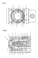
- FIG. 1 and 2 is a part of a turret body 1 of a turret with a receiving opening 2 and a turret body 1 arranged in the clamping device 3 for releasably holding a arranged in the receiving opening 2 tool holder 4 in a cross section and a sectional plan view shown.
- Tool turrets usually have a plurality of arranged in the turret body 1 receiving openings 2 for holding a plurality of tool holders or tools.
- the tool turret can be designed, for example, as a star turret with a disk-shaped turret body 1 and a plurality of receiving openings 2 distributed in a star-shaped manner on its outer circumference.
- the tool turret can also be designed as a disk turret with arranged on the front side of a revolver body receiving openings or may identify another suitable form.
- the tool turret is a star turret, in the disc-shaped turret body 1 more, with a specially adapted unit contour provided receiving openings 2 for receiving different tool holders 4 are arranged.
- the receiving opening 2 of the turret body 1 is repeatedly stepped in the embodiment shown and the tool holder 4 has a projecting into a lower region 5 of the receiving opening 2 lower chucking pin 6 with a conical upper clamping surface 7.
- the clamping pin 6 engages in the lower region 5 of the receiving opening 2 with a radial distance.
- a receiving socket 8 is inserted, which is designed here as a hypotrochoid and a in FIG. 5 recognizable inner contour 9 contains.
- other receiving sockets with other inner contours for differently shaped tool holders can be used in the receiving opening 2.
- the clamping device 3 comprises two mutually displaceable clamping elements 10 and 11, which are formed by a common actuator 12 in opposite directions transversely to a central axis 13 of the receiving opening 2 slidably and for gripping the clamping pin 6 on both sides.
- a common actuator 12 By trained here as a threaded bolt actuator 12, the two on opposite sides of the clamping pin 6 acting clamping elements 10 and 11 from a in the Figures 1 and 2 shown release position in the direction of the central axis 13 toward each other in one in the FIGS. 3 and 4 shown clamping position shifted or moved from this clamping position by moving apart of the clamping elements 10 and 11 back into the release position.
- the first clamping element 10 is in the form of a in the inner part 5 of the receiving opening 2 and arranged transversely to the central axis 13 of the receiving opening 2 displaceable ring with a laterally projecting guide pin 14 executed.
- the guide pin 14 of the annular clamping element 10 is guided displaceably in a guide bush 16 arranged within a transverse bore 15 of the turret body 1.
- the annular clamping element 10 has, on a side diametrically opposite the guide pin 14, an inwardly projecting clamping claw 17 with a lower clamping surface 18 for engagement with the conical clamping surface 7 on the clamping pin 6 of the tool holder 4.
- the guide pin 14 of the annular clamping element 10 has a provided with an internal threaded through hole 19, in a Threaded pin 20 engages formed as a set screw actuator 12.
- the second clamping element 11 is fastened via a screw 21 so that the actuating element 12 can rotate relative to the clamping element 11, but the clamping element 11 is axially secured and is taken along by an axial movement of the actuating element 12 through this.
- actuator 12 is a stud 23 for securing the screw 21 is arranged in the trained as a set screw with a hexagon socket 22 actuator 12 is a stud 23 for securing the screw 21 is arranged.
- the actuating element 12 has an annular collar 24, via which the actuating element 12, together with the guide pin 14 of the first clamping element 10, is displaceably guided in the guide bush 16.
- the guide bush 16 has at its outer end an annular shoulder 25, on which the annular collar 24 of the actuating element 12 in the in FIG. 6 comes to rest shown attachment.
- the second clamping element 11 is designed in the form of a ring segment and likewise has a laterally projecting guide pin 26. About the guide pin 26, the clamping element 11 is guided in the through hole 19 in the guide pin 14 of the first clamping element 10 slidably. Also on the second clamping element 11 an inwardly projecting clamping claw 27 is provided with a lower clamping surface 28 for engagement with the conical clamping surface 7 on the clamping pin 6 of the tool holder 4.
- the annular first clamping element 10 is in the receiving opening 2 of the turret body 1 by a also in FIG. 5 recognizable cover plate 29 and a spring ring 30 secured. In the first clamping element 10 can also in FIG. 1 recognizable and protruding through slots 31 in the cover plate 29 ejection pins 32 may be arranged for ejecting the tool holder 4 during the displacement of the clamping elements 10 and 11 in the release position.
- the two clamping elements 10 and 11 are formed such that they enclose the clamping pin 4 of the tool holder 4 from both sides.
- the two diametrically opposed clamping jaws 17 and 17 are designed as ring segments with an angle of 60 °. This achieves good clamping and retraction force.
Landscapes
- Engineering & Computer Science (AREA)
- Mechanical Engineering (AREA)
- Cutting Tools, Boring Holders, And Turrets (AREA)
Abstract
Description
- Die Erfindung betrifft einen Werkzeugrevolver nach dem Oberbegriff des Patentanspruchs 1.
- Aus der
EP 2 529 865 A1 ist ein Werkzeugrevolver bekannt, der einen scheibenförmigen Revolverkörper mit radialen Aufnahmeöffnungen für unterschiedliche Werkzeugaufnahmen enthält. Die Werkzeugaufnahmen sind über Schrauben an dem scheibenförmigen Revolverkörper befestigt und weisen einen in die Aufnahmeöffnungen ragenden Fortsatz auf. Zum Festklemmen der Werkzeuge in den Werkzeugaufnahmen ist in einer Querbohrung des Revolverkörpers ein an seinem vorderen Ende mit einem Außensechskant versehener Betätigungsbolzen axial verschiebbar geführt. Der Betätigungsbolzen wird durch eine Feder nach außen gedrückt und kann zum Spannen der Werkzeuge durch einen Schlüssel entgegen der Feder nach innen gedrückt werden. Bei diesem bekannten Werkzeugrevolver werden die Werkzeugaufnahmen nur einseitig gegen ein festes Widerlager gespannt. - Aufgabe der Erfindung ist es, einen Werkzeugrevolver der eingangs genannten Art zu schaffen, der einen gleichmäßigeren Spannvorgang ermöglicht.
- Diese Aufgabe wird durch einen Werkzeugrevolver mit den Merkmalen des Anspruchs 1 gelöst. Zweckmäßige Weiterbildungen und vorteilhafte Ausgestaltungen der Erfindung sind in den Unteransprüchen angegeben.
- Bei dem erfindungsgemäßen Werkzeugrevolver weist die Spannvorrichtung zwei durch ein gemeinsames Betätigungselement quer zu einer Mittelachse der Aufnahmeöffnung gegeneinander verschiebbare Spannelemente auf. Dadurch kann eine Werkzeugaufnahme gleichmäßiger gespannt werden. Selbst bei ungenauen Aufnahmen oder Verschmutzungen kann eine möglichst genaue zentrische Spannung erreicht werden. Unerwünschte Kippbewegungen oder Schrägstellungen der Werkzeugaufnahmen sind außerdem vermeidbar. Die entgegen gesetzte Verschiebung der beiden Spannelemente kann durch ein gemeinsames Betätigungselement erfolgen, wodurch eine einfache Bedienung ermöglicht wird. Die Spannvorrichtung kann auch besonders einfach montiert werden. Sie kann z.B. von oben in die Aufnahmeöffnungen der Revolverkörper eingesetzt und von außen montiert werden. Es sind keine aufwändigen Änderungen oder Anpassungen an dem Revolverkörper erforderlich.
- In einer besonders zweckmäßigen Ausführung weisen die beiden Spannelemente diametral gegenüberliegende Spannklauen mit einer konischen oder schrägen unteren Spannfläche zur Anlage an einer dazu korrespondierenden konischen oder schrägen oberen Spannfläche der Werkzeugaufnahme auf. Dadurch kann die Werkzeugaufnahme beim Spannen gleichmäßig in die Aufnahmeöffnung des Revolverkörpers eingezogen werden.
- Die beiden Spannelemente sind vorzugsweise derart ausgebildet, dass sie einen Spannzapfen der Werkzeugaufnahme von zwei Seiten umschließen. In einer besonders für angetriebene Werkzeuge geeigneten Ausführung kann das eine Spannelement in Form eines durch das Betätigungselement verschiebbaren Rings und das andere Spannelement in Form eines demgegenüber verschiebbaren Ringsegments ausgebildet sein. Durch das ringförmige Spannelement kann so ein Antrieb für die angetrieben Werkzeuge geführt werden. Für nicht angetriebene Werkzeuge können die Spannelemente aber auch als Schieber oder dgl. ausgeführt sein.
- Das erste Spannelement kann einen seitlich vorstehenden Führungszapfen enthalten, der in einer innerhalb einer Querbohrung des Revolverkörpers angeordneten Führungsbuchse verschiebbar geführt ist. Das zweite Spannelement kann über einen seitlich vorstehenden Führungszapfen in einer Durchgangsbohrung im Führungszapfen des ersten Spannelements verschiebbar geführt sein.
- Zweckmäßigerweise kann das Betätigungselement als Stellschraube mit einem Gewindezapfen ausgebildet sein, der in eine mit einem Innengewinde versehene Durchgangsbohrung im Führungszapfen des ersten Spannelements eingreift. Das Betätigungselement ist vorzugsweise in einer Führungsbuchse in Axialrichtung begrenzt verschiebbar angeordnet.
- Die Aufnahmeöffnung des Revolverkörpers kann eine Einheitskontur zur Aufnahme unterschiedlicher Werkzeugrevolveradapter aufweisen. In die Aufnahmeöffnung des Revolverkörpers kann eine Aufnahmebuchse eingesetzt sein. Dadurch kann der Werkzeugrevolver einfach an unterschiedliche Werkzeugaufnahmen angepasst werden.
- Weitere Besonderheiten und Vorzüge der Erfindung ergeben sich aus der folgenden Beschreibung bevorzugter Ausführungsbeispiele anhand der Zeichnung. Es zeigen:
- Figur 1
- einen Querschnitt durch einen Teil eines Werkzeugrevolvers mit einer Werkzeugaufnahme und einer Spannvorrichtung in einer Lösestellung;
- Figur 2
- eine Schnittansicht entlang der Linie E-E von
Figur 1 ; - Figur 3
- einen Querschnitt durch einen Teil des Werkzeugrevolver entsprechend
Figur 1 mit der Werkzeugaufnahme und der Spannvorrichtung in einer Spannstellung; - Figur 4
- eine Schnittansicht entlang der Linie F-F von
Figur 3 ; - Figur 5
- eine Draufsicht auf einen Teil des Werkzeugrevolvers von
Figur 1 und - Figur 6
- eine vergrößerte Darstellung der Spannvorrichtung in dem Werkzeugrevolver von
Figur 1 . - In den
Figuren 1 und 2 ist ein Teil eines Revolverkörpers 1 eines Werkzeugrevolvers mit einer Aufnahmeöffnung 2 und einer im Revolverkörper 1 angeordneten Spannvorrichtung 3 zur lösbaren Halterung einer in der Aufnahmeöffnung 2 angeordneten Werkzeugaufnahme 4 in einem Querschnitt und einer geschnittenen Draufsicht gezeigt. Werkzeugrevolver weisen üblicherweise mehrere in dem Revolverkörper 1 angeordnete Aufnahmeöffnungen 2 zur Halterung mehrerer Werkzeugaufnahmen oder Werkzeuge auf. - Der Werkzeugrevolver kann z.B. als Sternrevolver mit einem scheibenförmigen Revolverkörper 1 und mehreren an dessen Außenumfang sternförmig verteilten Aufnahmeöffnungen 2 ausgebildet sein. Der Werkzeugrevolver kann aber auch als Scheibenrevolver mit an der Stirnseite eines Revolverkörpers angeordneten Aufnahmeöffnungen ausgeführt sein oder kann eine andere geeignete Form ausweisen. Bei dem gezeigten Ausführungsbeispiel ist der Werkzeugrevolver ein Sternrevolver, in dessen scheibenförmigen Revolverkörper 1 mehrere, mit einer speziell angepassten Einheitskontur versehene Aufnahmeöffnungen 2 zur Aufnahme unterschiedlicher Werkzeugaufnahmen 4 angeordnet sind.
- Die Aufnahmeöffnung 2 des Revolverkörpers 1 ist bei der gezeigten Ausführung mehrfach abgestuft und die Werkzeugaufnahme 4 weist einen in einen unteren Bereich 5 der Aufnahmeöffnung 2 ragenden unteren Spannzapfen 6 mit einer konischen oberen Spannfläche 7 auf. Der Spannzapfen 6 greift in den unteren Bereich 5 der Aufnahmeöffnung 2 mit einem radialen Abstand ein. In die Aufnahmeöffnung 2 des Revolverkörpers ist eine Aufnahmebuchse 8 eingesetzt, die eine hier als Hypotrochoid ausgebildet ist und eine in
Figur 5 erkennbare Innenkontur 9 enthält. Selbstverständlich sind in die Aufnahmeöffnung 2 auch andere Aufnahmebuchsen mit anderen Innenkonturen für unterschiedlich gestaltete Werkzeugaufnahmen einsetzbar. - Die Spannvorrichtung 3 umfasst zwei gegeneinander verschiebbare Spannelemente 10 und 11, die durch ein gemeinsames Betätigungselement 12 in entgegen gesetzten Richtungen quer zu einer Mittelachse 13 der Aufnahmeöffnung 2 verschiebbar und zum beidseitigen Umgreifen des Spannzapfens 6 ausgebildet sind. Durch das hier als Gewindebolzen ausgebildete Betätigungselement 12 können die beiden an gegenüberliegenden Seiten des Spannzapfens 6 angreifenden Spannelemente 10 und 11 aus einer in den
Figuren 1 und 2 gezeigten Lösestellung in Richtung der Mittelachse 13 aufeinander zu in eine in denFiguren 3 und 4 gezeigte Spannstellung verschoben bzw. aus dieser Spannstellung durch Auseinanderfahren der Spannelemente 10 und 11 wieder in die Lösestellung bewegt werden. - Das erste Spannelement 10 ist in Form eines im inneren Teil 5 der Aufnahmeöffnung 2 angeordneten und quer zur Mittelachse 13 der Aufnahmeöffnung 2 verschiebbaren Rings mit einem seitlich vorstehenden Führungszapfen 14 ausgeführt. Der Führungszapfen 14 des ringförmigen Spannelements 10 ist in einer innerhalb einer Querbohrung 15 des Revolverkörpers 1 angeordneten Führungsbuchse 16 verschiebbar geführt. Das ringförmige Spannelement 10 weist an einer dem Führungszapfen 14 diametral gegenüberliegenden Seite eine nach innen vorstehende Spannklaue 17 mit einer unteren Spannfläche 18 zur Anlage an der konischen Spannfläche 7 am Spannzapfen 6 der Werkzeugaufnahme 4 auf.
- Wie besonders aus
Figur 6 hervorgeht, enthält der Führungszapfen 14 des ringförmigen Spannelements 10 eine mit einem Innengewinde versehene Durchgangsbohrung 19, in die ein Gewindezapfen 20 des als Stellschraube ausgebildeten Betätigungselements 12 eingreift. An dem Gewindezapfen 20 des Betätigungselements 12 ist das zweite Spannelement 11 über eine Schraube 21 so befestigt, dass sich das Betätigungselement 12 gegenüber dem Spannelement 11 drehen kann, das Spannelement 11 aber axial gesichert ist und bei einer Axialbewegung des Betätigungselements 12 durch dieses mitgenommen wird. In dem als Stellschraube mit einem Innensechskant 22 ausgebildeten Betätigungselement 12 ist eine Stiftschraube 23 zur Sicherung der Schraube 21 angeordnet. Das Betätigungselement 12 hat einen Ringbund 24, über den das Betätigungselement 12 zusammen mit dem Führungszapfen 14 des ersten Spannelements 10 verschiebbar in der Führungsbuchse 16 geführt ist. Die Führungsbuchse 16 weist an ihrem äußeren Ende eine Ringschulter 25 auf, an welcher der Ringbund 24 des Betätigungselements 12 in der inFigur 6 gezeigten Lösestellung zur Anlage gelangt. - Das zweite Spannelement 11 ist in Form eines Ringsegments ausgebildet und weist ebenfalls einen seitlich vorstehenden Führungszapfen 26 auf. Über den Führungszapfen 26 ist das Spannelement 11 in der Durchgangsbohrung 19 im Führungszapfen 14 des ersten Spannelements 10 verschiebbar geführt. Auch an dem zweiten Spannelement 11 ist eine nach innen vorstehende Spannklaue 27 mit einer unteren Spannfläche 28 zur Anlage an der konischen Spannfläche 7 am Spannzapfen 6 der Werkzeugaufnahme 4 vorgesehen. Das ringförmige erste Spannelement 10 ist in der Aufnahmeöffnung 2 des Revolverkörpers 1 durch eine auch in
Figur 5 erkennbare Deckscheibe 29 und einen Federring 30 gesichert. In dem ersten Spannelement 10 können auch inFigur 1 erkennbare und durch Langlöcher 31 in der Deckscheibe 29 ragenden Ausstoßstifte 32 zum Ausstoßen der Werkzeugaufnahme 4 bei der Verschiebung der Spannelemente 10 und 11 in die Lösestellung angeordnet sein. - Wie aus den
Figuren 2 und4 ersichtlich ist, sind die beiden Spannelemente 10 und 11 derart ausgebildet, dass sie den Spannzapfen 4 der Werkzeugaufnahme 4 von beiden Seiten umschließen. Die beiden diametral gegenüberliegenden Spannklauen 17 und 17 sind als Ringsegmente mit einem Winkel von 60° ausgeführt. Dadurch ist eine gute Spann- und Einzugskraft erreichbar. - Durch Drehung des als Stellschraube ausgebildeten Betätigungselements 12 werden die Spannelemente 10 und 11 zwischen der in den
Figuren 1 und 2 gezeigten Lösestellung und der in denFiguren 3 und 4 gezeigten Spannstellung verschoben. Wird z.B. das Betätigungselement 12 in der Lösestellung vonFigur 1 und 2 nach rechts gedreht, werden die beiden Spannelemente 10 und 11 über den Gewindezapfen 20 zusammengefahren und gegen den Spannzapfen 6 der Werkzeugaufnahme 4 gezogen. In der Spannstellung weisen die beiden Spannelemente 10 und 11 keine Abstützung an dem Revolverkörper 1 auf, wodurch die Entstehung von Kippmomenten vermieden werden kann. Durch entgegen gesetzte Drehung des Betätigungselements 12 können die beiden Spannelemente 10 und 11 wieder auseinander gefahren und in die Lösestellung derFiguren 1 und 2 bewegt werden.
Claims (10)
- Werkzeugrevolver mit einem Revolverkörper (1) und einer Spannvorrichtung (3) zur Spannen einer Werkzeugaufnahme (6) in einer Aufnahmeöffnung (2) des Revolverkörpers (1), dadurch gekennzeichnet, dass die Spannvorrichtung (3) zwei durch ein gemeinsames Betätigungselement (12) quer zu einer Mittelachse (13) der Aufnahmeöffnung (2) gegeneinander verschiebbare Spannelemente (10, 11) umfasst.
- Werkzeugrevolver nach Anspruch 1, dadurch gekennzeichnet, dass die beiden Spannelemente (10, 11) diametral gegenüberliegende Spannklauen (17, 27) mit einer unteren Spannfläche (18, 28) zur Anlage an einer oberen Spannfläche (7) der Werkzeugaufnahme (4) aufweisen.
- Werkzeugrevolver nach Anspruch 1 oder 2, dadurch gekennzeichnet, dass die beiden Spannelemente (10, 11) derart ausgebildet sind, dass sie einen Spannzapfen (6) der Werkzeugaufnahme (4) von zwei Seiten umschließen.
- Werkzeugrevolver nach einem der Ansprüche 1 bis 3, dadurch gekennzeichnet, dass ein erstes Spannelement (10) in Form eines Rings und ein zweites Spannelement (11) in Form eines demgegenüber verschiebbaren Ringsegments ausgebildet ist.
- Werkzeugrevolver nach Anspruch 4, dadurch gekennzeichnet, dass das erste Spannelement (10) einen seitlich vorstehenden Führungszapfen (14) enthält, der in einer innerhalb einer Querbohrung (15) des Revolverkörpers (1) angeordneten Führungsbuchse (16) verschiebbar geführt ist.
- Werkzeugrevolver nach Anspruch 5, dadurch gekennzeichnet, dass der Führungszapfen (14) des ersten Spannelements (10) eine mit einem Innengewinde versehene Durchgangsbohrung (19) enthält, in die ein Gewindezapfen (20) des als Stellschraube ausgebildeten Betätigungselements (12) eingreift.
- Werkzeugrevolver nach einem der Ansprüche 4 bis 6, dadurch gekennzeichnet, dass das erste Spannelement (10) durch einen Sicherungsring (30) gesichert in der Aufnahmeöffnung (2) des Revolverkörpers (1) angeordnet ist.
- Werkzeugrevolver nach einem der Ansprüche 4 bis 7, dadurch gekennzeichnet, dass zweite Spannelement (11) einen seitlich vorstehenden Führungszapfen (26) enthält, über den das zweite Spannelement (11) in einer Durchgangsbohrung (19) im Führungszapfen (14) des ersten Spannelements (10) verschiebbar geführt ist.
- Werkzeugrevolver nach einem der Ansprüche 1 bis 8, dadurch gekennzeichnet, dass das Betätigungselement (12) in einer Führungsbuchse (16) in Axialrichtung begrenzt verschiebbar angeordnet ist.
- Werkzeugrevolver nach einem der Ansprüche 1 bis 9, dadurch gekennzeichnet, dass in die Aufnahmeöffnung (2) des Revolverkörpers (1) eine Aufnahmebuchse (8) eingesetzt ist.
Applications Claiming Priority (1)
| Application Number | Priority Date | Filing Date | Title |
|---|---|---|---|
| DE102014102082.0A DE102014102082A1 (de) | 2014-02-19 | 2014-02-19 | Werkzeugrevolver |
Publications (2)
| Publication Number | Publication Date |
|---|---|
| EP2910325A1 true EP2910325A1 (de) | 2015-08-26 |
| EP2910325B1 EP2910325B1 (de) | 2019-03-13 |
Family
ID=52595044
Family Applications (1)
| Application Number | Title | Priority Date | Filing Date |
|---|---|---|---|
| EP15153634.9A Active EP2910325B1 (de) | 2014-02-19 | 2015-02-03 | Werkzeugrevolver |
Country Status (3)
| Country | Link |
|---|---|
| EP (1) | EP2910325B1 (de) |
| DE (1) | DE102014102082A1 (de) |
| ES (1) | ES2722298T3 (de) |
Cited By (1)
| Publication number | Priority date | Publication date | Assignee | Title |
|---|---|---|---|---|
| EP3771510A1 (de) * | 2019-07-30 | 2021-02-03 | ESA Eppinger GmbH | Werkzeugmaschine mit einem beweglichen werkzeugträger, werkzeugträger und werkzeughalter dafür |
Families Citing this family (2)
| Publication number | Priority date | Publication date | Assignee | Title |
|---|---|---|---|---|
| DE102016109275A1 (de) | 2016-05-20 | 2017-11-23 | Ott-Jakob Spanntechnik Gmbh | Werkzeugträger |
| DE102020120525A1 (de) | 2020-08-04 | 2022-02-10 | Ott-Jakob Spanntechnik Gmbh | Werkzeug- oder Werkstückaufnahme |
Citations (2)
| Publication number | Priority date | Publication date | Assignee | Title |
|---|---|---|---|---|
| DE102009011221A1 (de) * | 2009-03-04 | 2010-09-16 | Szm Spannwerkzeuge Gmbh | Spannvorrichtung für Hohlschaftwerkzeuge, insbesondere zum Einbau in eine Revolverscheibe |
| EP2529865A1 (de) | 2011-05-31 | 2012-12-05 | Su-Matic Corp | Revolverscheibe und Werkzeughalter für ein Bearbeitungswerkzeug |
Family Cites Families (15)
| Publication number | Priority date | Publication date | Assignee | Title |
|---|---|---|---|---|
| GB1567251A (en) * | 1976-08-24 | 1980-05-14 | Kennametal Inc | Connection arrangements for tool holders |
| EP0193020B1 (de) * | 1985-03-01 | 1990-11-28 | Fried. Krupp Gesellschaft mit beschränkter Haftung | Werkzeugeinrichtung mit wechselbarem Werkzeugkopf |
| DE3602247C2 (de) * | 1986-01-25 | 1997-01-23 | Widia Gmbh | Werkzeugkupplung zur Verbindung eines wechselbaren Werkzeugkopfes mit einem Werkzeughalter an einer Werkzeugmaschine |
| US4726268A (en) * | 1987-01-27 | 1988-02-23 | Kennametal Inc. | Clamping apparatus for holding a toolholder shank |
| DE3813670A1 (de) * | 1988-04-22 | 1989-11-02 | Ott Maschinentechnik | Kupplung zwischen zwei maschinenteilen |
| DE3814550C1 (en) * | 1988-04-29 | 1989-09-28 | A. Ott Gmbh, 8960 Kempten, De | Clamping device for clamping two machine parts releasable from one another |
| DE3926480A1 (de) * | 1989-08-10 | 1991-02-14 | Guehring Gottlieb Fa | Werkzeugwechselsystem fuer einen werkzeughalter mit stehendem und/oder drehangetriebenem werkzeug |
| DE4028775C1 (de) * | 1990-03-28 | 1991-07-25 | Ott Maschinentechnik Gmbh, 8960 Kempten, De | |
| DE4125003A1 (de) * | 1991-07-27 | 1993-01-28 | Index Werke Kg Hahn & Tessky | Werkzeugrevolver, insbesondere drehmaschinen |
| FR2768069B1 (fr) * | 1997-09-09 | 1999-11-12 | Sandvik Tobler | Dispositif de serrage et d'entrainement d'une piece prepositionnee |
| FR2788711B1 (fr) * | 1999-01-25 | 2001-03-09 | Sandvik Tobler | Mandrin a serrage adaptatif |
| FR2850306B1 (fr) * | 2003-01-29 | 2006-01-20 | Sandvik Tobler | Mandrin pince |
| DE102005008892A1 (de) * | 2005-02-26 | 2006-09-07 | Ott-Jakob Gmbh & Co. Spanntechnik Kg | Spannvorrichtung |
| DE102009022199B4 (de) * | 2009-05-20 | 2014-03-13 | MAPAL Fabrik für Präzisionswerkzeuge Dr. Kress KG | Werkzeugaufnahme |
| DE102013104874B3 (de) * | 2013-05-13 | 2014-12-04 | Ott-Jakob Spanntechnik Gmbh | Werkzeugrevolver |
-
2014
- 2014-02-19 DE DE102014102082.0A patent/DE102014102082A1/de not_active Withdrawn
-
2015
- 2015-02-03 EP EP15153634.9A patent/EP2910325B1/de active Active
- 2015-02-03 ES ES15153634T patent/ES2722298T3/es active Active
Patent Citations (2)
| Publication number | Priority date | Publication date | Assignee | Title |
|---|---|---|---|---|
| DE102009011221A1 (de) * | 2009-03-04 | 2010-09-16 | Szm Spannwerkzeuge Gmbh | Spannvorrichtung für Hohlschaftwerkzeuge, insbesondere zum Einbau in eine Revolverscheibe |
| EP2529865A1 (de) | 2011-05-31 | 2012-12-05 | Su-Matic Corp | Revolverscheibe und Werkzeughalter für ein Bearbeitungswerkzeug |
Cited By (8)
| Publication number | Priority date | Publication date | Assignee | Title |
|---|---|---|---|---|
| EP3771510A1 (de) * | 2019-07-30 | 2021-02-03 | ESA Eppinger GmbH | Werkzeugmaschine mit einem beweglichen werkzeugträger, werkzeugträger und werkzeughalter dafür |
| US20210031274A1 (en) * | 2019-07-30 | 2021-02-04 | Esa Eppinger Gmbh | Machine Tool Having a Movable Tool Carrier, Tool Carrier and Tool Holder Therefor |
| KR20210014585A (ko) * | 2019-07-30 | 2021-02-09 | 이에스에이 에핑어 게엠베하 | 이동식 공구 캐리어, 공구 캐리어 및 그에 따른 공구 홀더를 갖는 공작 기계 |
| JP2021041523A (ja) * | 2019-07-30 | 2021-03-18 | エーエスアー エッピンガー ゲーエムベーハー | 可動工具キャリアを有する工作機械、ならびに、その工具キャリアおよび工具ホルダ |
| US11583938B2 (en) * | 2019-07-30 | 2023-02-21 | Esa Eppinger Gmbh | Machine tool having a movable tool carrier, tool carrier and tool holder therefor |
| US11945035B2 (en) | 2019-07-30 | 2024-04-02 | Esa Eppinger Gmbh | Tool holder |
| EP4491309A3 (de) * | 2019-07-30 | 2025-04-09 | ESA Eppinger GmbH | Werkzeugmaschine mit einem beweglichen werkzeugträger, werkzeugträger und werkzeughalter dafür |
| EP4501505A3 (de) * | 2019-07-30 | 2025-05-14 | ESA Eppinger GmbH | Werkzeugmaschine mit einem beweglichen werkzeugträger, werkzeugträger und werkzeughalter dafür |
Also Published As
| Publication number | Publication date |
|---|---|
| DE102014102082A1 (de) | 2015-08-20 |
| ES2722298T3 (es) | 2019-08-09 |
| EP2910325B1 (de) | 2019-03-13 |
Similar Documents
| Publication | Publication Date | Title |
|---|---|---|
| DE2760399C2 (de) | ||
| DE2823766C3 (de) | Spannfutter | |
| DE3602247C2 (de) | Werkzeugkupplung zur Verbindung eines wechselbaren Werkzeugkopfes mit einem Werkzeughalter an einer Werkzeugmaschine | |
| DE3879756T2 (de) | Spannfutter, insbesondere fuer werkzeugmaschine. | |
| DE2744410A1 (de) | 4-backen-spannfutter fuer ein werkstueck | |
| EP1453630B1 (de) | Spannvorrichtung | |
| DE202008015100U1 (de) | Steckbolzen mit Klemmelementen | |
| DE3814550C1 (en) | Clamping device for clamping two machine parts releasable from one another | |
| EP2879824B1 (de) | Auswucht- oder messadapter | |
| DE102013104874B3 (de) | Werkzeugrevolver | |
| DE102018119980A1 (de) | Spann- oder Greifeinrichtung | |
| EP2910325B1 (de) | Werkzeugrevolver | |
| EP3165310B1 (de) | Spannvorrichtung | |
| DE102020122709A1 (de) | Spannvorrichtung | |
| CH703077B1 (de) | Vorrichtung mit einem Werkstückträger und einem an einer Bearbeitungsmaschine fixierbaren Spannfutter. | |
| DE102004008624A1 (de) | Aufnahmevorrichtung einer Meßeinrichtung | |
| DE102011116572A1 (de) | Spannvorrichtung und Werkzeughalter mit einer derartigen Spannvorrichtung | |
| EP3950193B1 (de) | Werkzeug- oder werkstückaufnahme | |
| EP3165309A1 (de) | Spannvorrichtung | |
| DE202015100071U1 (de) | Elastisches Spannfutter | |
| DE956008C (de) | Spannzangenfutter mit einem auf der Spannzange aufgeschraubten und gegen sie drehgesicherten Zugring | |
| DE102020101062B4 (de) | Werkstückspannvorrichtung mit Kopplungskörper zwischen Klemmkörper und Gewindespindel | |
| EP3246118B1 (de) | Werkzeugträger | |
| DE1602877C3 (de) | Spannfutter für Werkzeugmaschinen | |
| DE202010003378U1 (de) | Werkzeugwechselvorrichtung |
Legal Events
| Date | Code | Title | Description |
|---|---|---|---|
| PUAI | Public reference made under article 153(3) epc to a published international application that has entered the european phase |
Free format text: ORIGINAL CODE: 0009012 |
|
| AK | Designated contracting states |
Kind code of ref document: A1 Designated state(s): AL AT BE BG CH CY CZ DE DK EE ES FI FR GB GR HR HU IE IS IT LI LT LU LV MC MK MT NL NO PL PT RO RS SE SI SK SM TR |
|
| AX | Request for extension of the european patent |
Extension state: BA ME |
|
| 17P | Request for examination filed |
Effective date: 20160226 |
|
| RBV | Designated contracting states (corrected) |
Designated state(s): AL AT BE BG CH CY CZ DE DK EE ES FI FR GB GR HR HU IE IS IT LI LT LU LV MC MK MT NL NO PL PT RO RS SE SI SK SM TR |
|
| STAA | Information on the status of an ep patent application or granted ep patent |
Free format text: STATUS: EXAMINATION IS IN PROGRESS |
|
| 17Q | First examination report despatched |
Effective date: 20170315 |
|
| GRAP | Despatch of communication of intention to grant a patent |
Free format text: ORIGINAL CODE: EPIDOSNIGR1 |
|
| STAA | Information on the status of an ep patent application or granted ep patent |
Free format text: STATUS: GRANT OF PATENT IS INTENDED |
|
| INTG | Intention to grant announced |
Effective date: 20181116 |
|
| GRAS | Grant fee paid |
Free format text: ORIGINAL CODE: EPIDOSNIGR3 |
|
| GRAA | (expected) grant |
Free format text: ORIGINAL CODE: 0009210 |
|
| STAA | Information on the status of an ep patent application or granted ep patent |
Free format text: STATUS: THE PATENT HAS BEEN GRANTED |
|
| AK | Designated contracting states |
Kind code of ref document: B1 Designated state(s): AL AT BE BG CH CY CZ DE DK EE ES FI FR GB GR HR HU IE IS IT LI LT LU LV MC MK MT NL NO PL PT RO RS SE SI SK SM TR |
|
| REG | Reference to a national code |
Ref country code: GB Ref legal event code: FG4D Free format text: NOT ENGLISH |
|
| REG | Reference to a national code |
Ref country code: CH Ref legal event code: EP Ref country code: AT Ref legal event code: REF Ref document number: 1107032 Country of ref document: AT Kind code of ref document: T Effective date: 20190315 |
|
| REG | Reference to a national code |
Ref country code: IE Ref legal event code: FG4D Free format text: LANGUAGE OF EP DOCUMENT: GERMAN |
|
| REG | Reference to a national code |
Ref country code: DE Ref legal event code: R096 Ref document number: 502015008292 Country of ref document: DE |
|
| REG | Reference to a national code |
Ref country code: NL Ref legal event code: MP Effective date: 20190313 |
|
| REG | Reference to a national code |
Ref country code: LT Ref legal event code: MG4D |
|
| PG25 | Lapsed in a contracting state [announced via postgrant information from national office to epo] |
Ref country code: SE Free format text: LAPSE BECAUSE OF FAILURE TO SUBMIT A TRANSLATION OF THE DESCRIPTION OR TO PAY THE FEE WITHIN THE PRESCRIBED TIME-LIMIT Effective date: 20190313 Ref country code: LT Free format text: LAPSE BECAUSE OF FAILURE TO SUBMIT A TRANSLATION OF THE DESCRIPTION OR TO PAY THE FEE WITHIN THE PRESCRIBED TIME-LIMIT Effective date: 20190313 Ref country code: FI Free format text: LAPSE BECAUSE OF FAILURE TO SUBMIT A TRANSLATION OF THE DESCRIPTION OR TO PAY THE FEE WITHIN THE PRESCRIBED TIME-LIMIT Effective date: 20190313 Ref country code: NO Free format text: LAPSE BECAUSE OF FAILURE TO SUBMIT A TRANSLATION OF THE DESCRIPTION OR TO PAY THE FEE WITHIN THE PRESCRIBED TIME-LIMIT Effective date: 20190613 |
|
| REG | Reference to a national code |
Ref country code: ES Ref legal event code: FG2A Ref document number: 2722298 Country of ref document: ES Kind code of ref document: T3 Effective date: 20190809 |
|
| PG25 | Lapsed in a contracting state [announced via postgrant information from national office to epo] |
Ref country code: BG Free format text: LAPSE BECAUSE OF FAILURE TO SUBMIT A TRANSLATION OF THE DESCRIPTION OR TO PAY THE FEE WITHIN THE PRESCRIBED TIME-LIMIT Effective date: 20190613 Ref country code: NL Free format text: LAPSE BECAUSE OF FAILURE TO SUBMIT A TRANSLATION OF THE DESCRIPTION OR TO PAY THE FEE WITHIN THE PRESCRIBED TIME-LIMIT Effective date: 20190313 Ref country code: LV Free format text: LAPSE BECAUSE OF FAILURE TO SUBMIT A TRANSLATION OF THE DESCRIPTION OR TO PAY THE FEE WITHIN THE PRESCRIBED TIME-LIMIT Effective date: 20190313 Ref country code: RS Free format text: LAPSE BECAUSE OF FAILURE TO SUBMIT A TRANSLATION OF THE DESCRIPTION OR TO PAY THE FEE WITHIN THE PRESCRIBED TIME-LIMIT Effective date: 20190313 Ref country code: GR Free format text: LAPSE BECAUSE OF FAILURE TO SUBMIT A TRANSLATION OF THE DESCRIPTION OR TO PAY THE FEE WITHIN THE PRESCRIBED TIME-LIMIT Effective date: 20190614 Ref country code: HR Free format text: LAPSE BECAUSE OF FAILURE TO SUBMIT A TRANSLATION OF THE DESCRIPTION OR TO PAY THE FEE WITHIN THE PRESCRIBED TIME-LIMIT Effective date: 20190313 |
|
| PG25 | Lapsed in a contracting state [announced via postgrant information from national office to epo] |
Ref country code: PT Free format text: LAPSE BECAUSE OF FAILURE TO SUBMIT A TRANSLATION OF THE DESCRIPTION OR TO PAY THE FEE WITHIN THE PRESCRIBED TIME-LIMIT Effective date: 20190713 Ref country code: SK Free format text: LAPSE BECAUSE OF FAILURE TO SUBMIT A TRANSLATION OF THE DESCRIPTION OR TO PAY THE FEE WITHIN THE PRESCRIBED TIME-LIMIT Effective date: 20190313 Ref country code: AL Free format text: LAPSE BECAUSE OF FAILURE TO SUBMIT A TRANSLATION OF THE DESCRIPTION OR TO PAY THE FEE WITHIN THE PRESCRIBED TIME-LIMIT Effective date: 20190313 Ref country code: EE Free format text: LAPSE BECAUSE OF FAILURE TO SUBMIT A TRANSLATION OF THE DESCRIPTION OR TO PAY THE FEE WITHIN THE PRESCRIBED TIME-LIMIT Effective date: 20190313 Ref country code: CZ Free format text: LAPSE BECAUSE OF FAILURE TO SUBMIT A TRANSLATION OF THE DESCRIPTION OR TO PAY THE FEE WITHIN THE PRESCRIBED TIME-LIMIT Effective date: 20190313 Ref country code: RO Free format text: LAPSE BECAUSE OF FAILURE TO SUBMIT A TRANSLATION OF THE DESCRIPTION OR TO PAY THE FEE WITHIN THE PRESCRIBED TIME-LIMIT Effective date: 20190313 |
|
| PG25 | Lapsed in a contracting state [announced via postgrant information from national office to epo] |
Ref country code: SM Free format text: LAPSE BECAUSE OF FAILURE TO SUBMIT A TRANSLATION OF THE DESCRIPTION OR TO PAY THE FEE WITHIN THE PRESCRIBED TIME-LIMIT Effective date: 20190313 Ref country code: PL Free format text: LAPSE BECAUSE OF FAILURE TO SUBMIT A TRANSLATION OF THE DESCRIPTION OR TO PAY THE FEE WITHIN THE PRESCRIBED TIME-LIMIT Effective date: 20190313 |
|
| REG | Reference to a national code |
Ref country code: DE Ref legal event code: R097 Ref document number: 502015008292 Country of ref document: DE |
|
| PG25 | Lapsed in a contracting state [announced via postgrant information from national office to epo] |
Ref country code: IS Free format text: LAPSE BECAUSE OF FAILURE TO SUBMIT A TRANSLATION OF THE DESCRIPTION OR TO PAY THE FEE WITHIN THE PRESCRIBED TIME-LIMIT Effective date: 20190713 |
|
| PLBE | No opposition filed within time limit |
Free format text: ORIGINAL CODE: 0009261 |
|
| STAA | Information on the status of an ep patent application or granted ep patent |
Free format text: STATUS: NO OPPOSITION FILED WITHIN TIME LIMIT |
|
| PG25 | Lapsed in a contracting state [announced via postgrant information from national office to epo] |
Ref country code: DK Free format text: LAPSE BECAUSE OF FAILURE TO SUBMIT A TRANSLATION OF THE DESCRIPTION OR TO PAY THE FEE WITHIN THE PRESCRIBED TIME-LIMIT Effective date: 20190313 |
|
| 26N | No opposition filed |
Effective date: 20191216 |
|
| PG25 | Lapsed in a contracting state [announced via postgrant information from national office to epo] |
Ref country code: SI Free format text: LAPSE BECAUSE OF FAILURE TO SUBMIT A TRANSLATION OF THE DESCRIPTION OR TO PAY THE FEE WITHIN THE PRESCRIBED TIME-LIMIT Effective date: 20190313 |
|
| PG25 | Lapsed in a contracting state [announced via postgrant information from national office to epo] |
Ref country code: TR Free format text: LAPSE BECAUSE OF FAILURE TO SUBMIT A TRANSLATION OF THE DESCRIPTION OR TO PAY THE FEE WITHIN THE PRESCRIBED TIME-LIMIT Effective date: 20190313 |
|
| REG | Reference to a national code |
Ref country code: CH Ref legal event code: PL |
|
| REG | Reference to a national code |
Ref country code: BE Ref legal event code: MM Effective date: 20200229 |
|
| PG25 | Lapsed in a contracting state [announced via postgrant information from national office to epo] |
Ref country code: MC Free format text: LAPSE BECAUSE OF FAILURE TO SUBMIT A TRANSLATION OF THE DESCRIPTION OR TO PAY THE FEE WITHIN THE PRESCRIBED TIME-LIMIT Effective date: 20190313 Ref country code: LU Free format text: LAPSE BECAUSE OF NON-PAYMENT OF DUE FEES Effective date: 20200203 |
|
| PG25 | Lapsed in a contracting state [announced via postgrant information from national office to epo] |
Ref country code: CH Free format text: LAPSE BECAUSE OF NON-PAYMENT OF DUE FEES Effective date: 20200229 Ref country code: LI Free format text: LAPSE BECAUSE OF NON-PAYMENT OF DUE FEES Effective date: 20200229 |
|
| PG25 | Lapsed in a contracting state [announced via postgrant information from national office to epo] |
Ref country code: IE Free format text: LAPSE BECAUSE OF NON-PAYMENT OF DUE FEES Effective date: 20200203 |
|
| PG25 | Lapsed in a contracting state [announced via postgrant information from national office to epo] |
Ref country code: BE Free format text: LAPSE BECAUSE OF NON-PAYMENT OF DUE FEES Effective date: 20200229 |
|
| REG | Reference to a national code |
Ref country code: AT Ref legal event code: MM01 Ref document number: 1107032 Country of ref document: AT Kind code of ref document: T Effective date: 20200203 |
|
| PG25 | Lapsed in a contracting state [announced via postgrant information from national office to epo] |
Ref country code: AT Free format text: LAPSE BECAUSE OF NON-PAYMENT OF DUE FEES Effective date: 20200203 |
|
| PG25 | Lapsed in a contracting state [announced via postgrant information from national office to epo] |
Ref country code: MT Free format text: LAPSE BECAUSE OF FAILURE TO SUBMIT A TRANSLATION OF THE DESCRIPTION OR TO PAY THE FEE WITHIN THE PRESCRIBED TIME-LIMIT Effective date: 20190313 Ref country code: CY Free format text: LAPSE BECAUSE OF FAILURE TO SUBMIT A TRANSLATION OF THE DESCRIPTION OR TO PAY THE FEE WITHIN THE PRESCRIBED TIME-LIMIT Effective date: 20190313 |
|
| PG25 | Lapsed in a contracting state [announced via postgrant information from national office to epo] |
Ref country code: MK Free format text: LAPSE BECAUSE OF FAILURE TO SUBMIT A TRANSLATION OF THE DESCRIPTION OR TO PAY THE FEE WITHIN THE PRESCRIBED TIME-LIMIT Effective date: 20190313 |
|
| PGFP | Annual fee paid to national office [announced via postgrant information from national office to epo] |
Ref country code: GB Payment date: 20260219 Year of fee payment: 12 |
|
| PGFP | Annual fee paid to national office [announced via postgrant information from national office to epo] |
Ref country code: ES Payment date: 20260319 Year of fee payment: 12 |
|
| PGFP | Annual fee paid to national office [announced via postgrant information from national office to epo] |
Ref country code: DE Payment date: 20260306 Year of fee payment: 12 |
|
| PGFP | Annual fee paid to national office [announced via postgrant information from national office to epo] |
Ref country code: IT Payment date: 20260227 Year of fee payment: 12 |
|
| PGFP | Annual fee paid to national office [announced via postgrant information from national office to epo] |
Ref country code: FR Payment date: 20260223 Year of fee payment: 12 |