EP2910329A2 - Laserverarbeitungsvorrichtung und Laserverarbeitungsverfahren - Google Patents
Laserverarbeitungsvorrichtung und Laserverarbeitungsverfahren Download PDFInfo
- Publication number
- EP2910329A2 EP2910329A2 EP15155807.9A EP15155807A EP2910329A2 EP 2910329 A2 EP2910329 A2 EP 2910329A2 EP 15155807 A EP15155807 A EP 15155807A EP 2910329 A2 EP2910329 A2 EP 2910329A2
- Authority
- EP
- European Patent Office
- Prior art keywords
- treated
- liquid
- gas
- laser processing
- laser
- Prior art date
- Legal status (The legal status is an assumption and is not a legal conclusion. Google has not performed a legal analysis and makes no representation as to the accuracy of the status listed.)
- Granted
Links
- 238000012545 processing Methods 0.000 title claims abstract description 65
- 238000003672 processing method Methods 0.000 title claims description 9
- 239000007788 liquid Substances 0.000 claims abstract description 89
- 230000007246 mechanism Effects 0.000 claims abstract description 46
- 230000005855 radiation Effects 0.000 claims abstract description 31
- 238000004381 surface treatment Methods 0.000 claims abstract description 8
- XLYOFNOQVPJJNP-UHFFFAOYSA-N water Substances O XLYOFNOQVPJJNP-UHFFFAOYSA-N 0.000 claims description 4
- 239000007789 gas Substances 0.000 description 66
- 239000012530 fluid Substances 0.000 description 47
- 239000010419 fine particle Substances 0.000 description 13
- 239000002184 metal Substances 0.000 description 13
- 229910052751 metal Inorganic materials 0.000 description 13
- 230000005494 condensation Effects 0.000 description 10
- 238000009833 condensation Methods 0.000 description 10
- 238000009792 diffusion process Methods 0.000 description 6
- 239000010935 stainless steel Substances 0.000 description 6
- 229910001220 stainless steel Inorganic materials 0.000 description 6
- 230000003028 elevating effect Effects 0.000 description 5
- IJGRMHOSHXDMSA-UHFFFAOYSA-N Atomic nitrogen Chemical compound N#N IJGRMHOSHXDMSA-UHFFFAOYSA-N 0.000 description 4
- 238000000034 method Methods 0.000 description 4
- 230000003405 preventing effect Effects 0.000 description 4
- 230000004048 modification Effects 0.000 description 3
- 238000012986 modification Methods 0.000 description 3
- 230000003287 optical effect Effects 0.000 description 3
- XKRFYHLGVUSROY-UHFFFAOYSA-N Argon Chemical compound [Ar] XKRFYHLGVUSROY-UHFFFAOYSA-N 0.000 description 2
- 230000005540 biological transmission Effects 0.000 description 2
- 238000010276 construction Methods 0.000 description 2
- 230000000694 effects Effects 0.000 description 2
- 229910052757 nitrogen Inorganic materials 0.000 description 2
- 230000003647 oxidation Effects 0.000 description 2
- 238000007254 oxidation reaction Methods 0.000 description 2
- 239000000941 radioactive substance Substances 0.000 description 2
- 229910000838 Al alloy Inorganic materials 0.000 description 1
- 229910052786 argon Inorganic materials 0.000 description 1
- 230000008859 change Effects 0.000 description 1
- 238000006243 chemical reaction Methods 0.000 description 1
- 238000001816 cooling Methods 0.000 description 1
- 239000000110 cooling liquid Substances 0.000 description 1
- 230000007797 corrosion Effects 0.000 description 1
- 238000005260 corrosion Methods 0.000 description 1
- 238000005336 cracking Methods 0.000 description 1
- 238000005202 decontamination Methods 0.000 description 1
- 230000003588 decontaminative effect Effects 0.000 description 1
- 230000007423 decrease Effects 0.000 description 1
- 238000011161 development Methods 0.000 description 1
- 230000007613 environmental effect Effects 0.000 description 1
- 230000005484 gravity Effects 0.000 description 1
- 238000007689 inspection Methods 0.000 description 1
- 238000012423 maintenance Methods 0.000 description 1
- 239000000463 material Substances 0.000 description 1
- 230000008569 process Effects 0.000 description 1
- 238000011084 recovery Methods 0.000 description 1
- 230000009467 reduction Effects 0.000 description 1
- 238000000926 separation method Methods 0.000 description 1
- 230000035939 shock Effects 0.000 description 1
- 238000005480 shot peening Methods 0.000 description 1
- 239000007921 spray Substances 0.000 description 1
- 238000006467 substitution reaction Methods 0.000 description 1
Images


Classifications
-
- B—PERFORMING OPERATIONS; TRANSPORTING
- B23—MACHINE TOOLS; METAL-WORKING NOT OTHERWISE PROVIDED FOR
- B23P—METAL-WORKING NOT OTHERWISE PROVIDED FOR; COMBINED OPERATIONS; UNIVERSAL MACHINE TOOLS
- B23P6/00—Restoring or reconditioning objects
- B23P6/04—Repairing fractures or cracked metal parts or products, e.g. castings
-
- B—PERFORMING OPERATIONS; TRANSPORTING
- B23—MACHINE TOOLS; METAL-WORKING NOT OTHERWISE PROVIDED FOR
- B23K—SOLDERING OR UNSOLDERING; WELDING; CLADDING OR PLATING BY SOLDERING OR WELDING; CUTTING BY APPLYING HEAT LOCALLY, e.g. FLAME CUTTING; WORKING BY LASER BEAM
- B23K26/00—Working by laser beam, e.g. welding, cutting or boring
- B23K26/02—Positioning or observing the workpiece, e.g. with respect to the point of impact; Aligning, aiming or focusing the laser beam
- B23K26/06—Shaping the laser beam, e.g. by masks or multi-focusing
- B23K26/062—Shaping the laser beam, e.g. by masks or multi-focusing by direct control of the laser beam
- B23K26/0622—Shaping the laser beam, e.g. by masks or multi-focusing by direct control of the laser beam by shaping pulses
-
- B—PERFORMING OPERATIONS; TRANSPORTING
- B23—MACHINE TOOLS; METAL-WORKING NOT OTHERWISE PROVIDED FOR
- B23K—SOLDERING OR UNSOLDERING; WELDING; CLADDING OR PLATING BY SOLDERING OR WELDING; CUTTING BY APPLYING HEAT LOCALLY, e.g. FLAME CUTTING; WORKING BY LASER BEAM
- B23K26/00—Working by laser beam, e.g. welding, cutting or boring
- B23K26/08—Devices involving relative movement between laser beam and workpiece
- B23K26/10—Devices involving relative movement between laser beam and workpiece using a fixed support, i.e. involving moving the laser beam
- B23K26/103—Devices involving relative movement between laser beam and workpiece using a fixed support, i.e. involving moving the laser beam the laser beam rotating around the fixed workpiece
-
- B—PERFORMING OPERATIONS; TRANSPORTING
- B23—MACHINE TOOLS; METAL-WORKING NOT OTHERWISE PROVIDED FOR
- B23K—SOLDERING OR UNSOLDERING; WELDING; CLADDING OR PLATING BY SOLDERING OR WELDING; CUTTING BY APPLYING HEAT LOCALLY, e.g. FLAME CUTTING; WORKING BY LASER BEAM
- B23K26/00—Working by laser beam, e.g. welding, cutting or boring
- B23K26/14—Working by laser beam, e.g. welding, cutting or boring using a fluid stream, e.g. a jet of gas, in conjunction with the laser beam; Nozzles therefor
- B23K26/146—Working by laser beam, e.g. welding, cutting or boring using a fluid stream, e.g. a jet of gas, in conjunction with the laser beam; Nozzles therefor the fluid stream containing a liquid
-
- B—PERFORMING OPERATIONS; TRANSPORTING
- B23—MACHINE TOOLS; METAL-WORKING NOT OTHERWISE PROVIDED FOR
- B23K—SOLDERING OR UNSOLDERING; WELDING; CLADDING OR PLATING BY SOLDERING OR WELDING; CUTTING BY APPLYING HEAT LOCALLY, e.g. FLAME CUTTING; WORKING BY LASER BEAM
- B23K26/00—Working by laser beam, e.g. welding, cutting or boring
- B23K26/352—Working by laser beam, e.g. welding, cutting or boring for surface treatment
-
- B—PERFORMING OPERATIONS; TRANSPORTING
- B23—MACHINE TOOLS; METAL-WORKING NOT OTHERWISE PROVIDED FOR
- B23K—SOLDERING OR UNSOLDERING; WELDING; CLADDING OR PLATING BY SOLDERING OR WELDING; CUTTING BY APPLYING HEAT LOCALLY, e.g. FLAME CUTTING; WORKING BY LASER BEAM
- B23K26/00—Working by laser beam, e.g. welding, cutting or boring
- B23K26/70—Auxiliary operations or equipment
- B23K26/702—Auxiliary equipment
-
- G—PHYSICS
- G21—NUCLEAR PHYSICS; NUCLEAR ENGINEERING
- G21C—NUCLEAR REACTORS
- G21C17/00—Monitoring; Testing ; Maintaining
- G21C17/003—Remote inspection of vessels, e.g. pressure vessels
-
- G—PHYSICS
- G21—NUCLEAR PHYSICS; NUCLEAR ENGINEERING
- G21C—NUCLEAR REACTORS
- G21C17/00—Monitoring; Testing ; Maintaining
- G21C17/02—Devices or arrangements for monitoring coolant or moderator
- G21C17/022—Devices or arrangements for monitoring coolant or moderator for monitoring liquid coolants or moderators
- G21C17/0225—Chemical surface treatment, e.g. corrosion
-
- G—PHYSICS
- G21—NUCLEAR PHYSICS; NUCLEAR ENGINEERING
- G21C—NUCLEAR REACTORS
- G21C19/00—Arrangements for treating, for handling, or for facilitating the handling of, fuel or other materials which are used within the reactor, e.g. within its pressure vessel
- G21C19/20—Arrangements for introducing objects into the pressure vessel; Arrangements for handling objects within the pressure vessel; Arrangements for removing objects from the pressure vessel
- G21C19/207—Assembling, maintenance or repair of reactor components
-
- B—PERFORMING OPERATIONS; TRANSPORTING
- B23—MACHINE TOOLS; METAL-WORKING NOT OTHERWISE PROVIDED FOR
- B23K—SOLDERING OR UNSOLDERING; WELDING; CLADDING OR PLATING BY SOLDERING OR WELDING; CUTTING BY APPLYING HEAT LOCALLY, e.g. FLAME CUTTING; WORKING BY LASER BEAM
- B23K2101/00—Articles made by soldering, welding or cutting
- B23K2101/04—Tubular or hollow articles
- B23K2101/06—Tubes
-
- G—PHYSICS
- G21—NUCLEAR PHYSICS; NUCLEAR ENGINEERING
- G21C—NUCLEAR REACTORS
- G21C17/00—Monitoring; Testing ; Maintaining
- G21C17/017—Inspection or maintenance of pipe-lines or tubes in nuclear installations
-
- Y—GENERAL TAGGING OF NEW TECHNOLOGICAL DEVELOPMENTS; GENERAL TAGGING OF CROSS-SECTIONAL TECHNOLOGIES SPANNING OVER SEVERAL SECTIONS OF THE IPC; TECHNICAL SUBJECTS COVERED BY FORMER USPC CROSS-REFERENCE ART COLLECTIONS [XRACs] AND DIGESTS
- Y02—TECHNOLOGIES OR APPLICATIONS FOR MITIGATION OR ADAPTATION AGAINST CLIMATE CHANGE
- Y02E—REDUCTION OF GREENHOUSE GAS [GHG] EMISSIONS, RELATED TO ENERGY GENERATION, TRANSMISSION OR DISTRIBUTION
- Y02E30/00—Energy generation of nuclear origin
- Y02E30/30—Nuclear fission reactors
Definitions
- Embodiments of the present invention relate to a laser processing apparatus and a laser processing method.
- Fig. 1 is a conceptual view illustrating a principle of the laser processing.
- a laser beam 1 having a pulse width of about several nanoseconds (ns) is condensed to a spot of a diameter of about 1 mm by a condenser lens 2 and radiated to a member to be treated 3, the surface of the member to be treated 3 absorbs energy to form into plasma.
- the periphery of plasma 4 is covered with liquid 6 having a transparency with respect to the wavelength of the laser beam 1, expansion of the plasma 4 is hindered so that internal pressure of the plasma 4 reaches several gigapascals (GPa) and makes an impact on the member to be treated 3.
- GPa gigapascals
- the above-described laser processing has an effect that less depends on a material strength and extends down to the inside of a plate thickness of about 1 mm from the surface of the member to be treated, as compared with another peening technique such as a shot peening, a water-jet peening or the like. Further, the laser processing provides excellent processability at a confined portion because there is no reaction force during processing and its processing apparatus can be easily downsized.
- the member to be treated is abraded during radiation of the laser beam to produce metal fine particles.
- impact of plasma generated by the radiation of the laser beam and heat generated during the radiation of the laser beam cause a part of the supplied liquid to form into a misty fluid, resulting in release of a misty fluid containing metal fine particles into the air environment.
- the member to be treated is a radioactive substance
- diffusion of the misty fluid not only increases the radiation dose in the air environment but also contaminates the apparatus used for processing and a shield wall surface, and therefore a decontamination work is possibly required.
- the member to be treated is not a radioactive substance, it is not preferable that floating metal fine particles adhere to the surroundings or sucked into the human body in some cases.
- Embodiments described below have been made to cope with the above problems and an object is to provide a laser processing apparatus and a laser processing method capable of suppressing diffusion of a misty fluid containing metal fine particles produced during processing of an member to be treated placed in an air environment.
- a laser processing apparatus is a laser processing apparatus for radiating a laser beam to a member to be treated provided in an air environment to perform surface treatment.
- the member to be treated forms a structure extending in a vertical direction.
- the laser processing apparatus includes: a liquid supply mechanism that jets and supplies liquid to a surface of the member to be treated; a laser radiation mechanism that radiates the laser beam in pulses to the surface of the member to be treated via the liquid; and a cylindrical gas laminar flow nozzle disposed below the liquid supply mechanism and configured to jet a gas upward to form a gas flow surrounding the member to be treated around an axis direction thereof.
- a laser processing method is a laser processing method of radiating a laser beam to a member to be treated provided in an air environment to perform surface treatment.
- the member to be treated forms a structure extending in a vertical direction.
- the laser processing method includes: while supplying liquid to a surface of the member to be treated; radiating the laser beam in pulses to the surface of the member to be treated via the liquid; and jetting a gas upward from lower position than a position of the member to be treated to form a gas flow surrounding the member to be treated around an axis direction thereof.
- Figs. 2 , 3 are views illustrating a schematic configuration of a laser radiation unit 100 in a laser processing apparatus according to a first embodiment.
- the laser radiation unit 100 includes a liquid jetting nozzle 102, and a suction nozzle 101 as a misty fluid collection mechanism is arranged near the liquid jetting nozzle 102.
- the liquid jetting nozzle 102 is configured such that its tip can be driven in an inclined direction.
- the liquid jetting nozzle 102 is configured to be able to perform three-dimensional scanning using three driving systems, that is, a driving device elevating shaft 103 that enables driving in the vertical direction, a driving device horizontal shaft 104 that enables driving in the horizontal direction, and a driving device rotating shaft 105 that enables driving in the rotation direction.
- a laser oscillator 106 is arranged on the driving device rotating shaft 105.
- an optical transmission system is built in for transmitting a laser beam 1 emitted from the laser oscillator 106 to the liquid jetting nozzle 102.
- the optical transmission system is composed of an all-reflective mirror 109, a condenser lens 2 installed on an optical path and so on.
- a part of the all-reflective mirror 109 is configured to be driven with driving of the driving device horizontal shaft 104 and the driving device elevating shaft 103.
- the laser beam 1 emitted from the laser oscillator 106 is transmitted while being reflected off the all-reflective mirror 109 and condensed by the condenser lens 2, and reaches the inside of the liquid jetting nozzle 102.
- the liquid jetting nozzle 102 is supplied with liquid 110 from a liquid supply mechanism 207 (see Fig. 4 ), and the laser beam 1 is transmitted to the liquid 110 and coaxially radiated into a liquid flow of the liquid 110 to be jetted from the tip of the liquid jetting nozzle 102.
- the laser beam 1 radiated into the liquid 110 is transmitted through the liquid 110 and radiated to a member to be treated 3 having a surface in contact with a liquid film of the liquid 110. This produces plasma 4 on the surface of the member to be treated 3, thereby making it possible to relax the residual stress of the member to be treated 3 on the above-described principle of laser processing.
- the liquid 110 after the laser processing a part thereof becomes a finer misty fluid 111 by the plasma 4, another part thereof becomes a liquid drop 112 due to collision with the member to be treated 3, and the remainder becomes a surface flow liquid 113 flowing on the surface of the member to be treated 3.
- Each of them contains metal fine particles of the member to be treated 3 produced during laser radiation, and the liquid drop 112 and the surface flow liquid 113 are easy to recover because they fall to the vicinity of the member to be treated 3 by the gravity without diffusion in a wide range.
- the misty fluid 111 comes into a state of floating in the air and therefore may drift in the air and diffuse to an undesired part.
- sucking the misty fluid 111 containing metal fine particles through use of the suction nozzle 101 and recovering the sucked misty fluid 111 via a suction mechanism 206 makes it possible to prevent the misty fluid 111 containing metal fine particles from diffusing to an undesired part.
- Fig. 4 illustrates the whole configuration of the laser processing apparatus in the case of performing laser processing on a nozzle stub of a nuclear reactor pressure vessel upper cover of a pressurized water reactor.
- a nuclear reactor pressure vessel upper cover 202 detached from a nuclear reactor pressure vessel is placed in an air environment while being supported by a plurality of support columns 204.
- a concrete biological shield 205 and a stainless steel shield 203 are installed for radiation protection.
- the laser radiation unit 100 of the laser processing apparatus is connected to an access mechanism 211 composed of a robot arm and the like installed inside the concrete biological shield 205 and the stainless steel shield 203, via an access mechanism connection unit 114.
- the access mechanism 211 allows the laser radiation unit 100 to get access to the vicinity of a nuclear reactor upper cover nozzle stub 201 welded to the nuclear reactor pressure vessel upper cover 202 and perform laser processing on a desired part.
- the liquid supply mechanism 207 that supplies the liquid necessary for the laser processing and a laser control mechanism 208 that supplies power to and controls the laser radiation unit 100 are arranged outside the concrete biological shield 205 and the stainless steel shield 203 to allow an operator to get access thereto.
- the liquid supply mechanism 207 and the laser control mechanism 208 are configured to supply the liquid, signal and so on necessary for the operation and laser processing of the laser radiation unit 100 by means of a liquid supply tube 107, and a cooling liquid circulation mechanism and control signal cable 209, respectively.
- the misty fluid 111 recovered from the suction nozzle 101 installed in the laser radiation unit 100 is led to the suction mechanism 206 arranged outside the concrete biological shield 205 and the stainless steel shield 203 via a suction tube 108 and recovered, separated into liquid and metal fine particles by a gas/liquid separation mechanism provided in the suction mechanism 206.
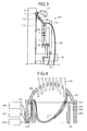
- a laser processing apparatus according to a second embodiment will be described referring to Fig. 5 .
- components in Fig. 5 corresponding to those of the laser processing apparatus according to the first embodiment are given the same reference numerals, and repeated description will be omitted.
- the second embodiment is configured such that the suction nozzle 101 arranged near the liquid jetting nozzle 102 in the first embodiment is arranged at the access mechanism 211. Arranging the suction nozzle 101 at the access mechanism 211 enables reduction in weight of a laser radiation unit 100a.
- the recovery rate of the misty fluid 111 near the laser radiation unit 100a decreases, but it is possible to recover the misty fluid 111 in a space surrounded by the nuclear reactor pressure vessel upper cover 202, the concrete biological shield 205, and the stainless steel shield 203 so as to prevent the misty fluid 111 from diffusing from the inside of the space to the outside.
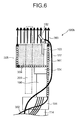
- a laser processing apparatus according to a third embodiment will be described referring to Fig. 6 to Fig. 9 .
- components in Figs. 6 to 9 corresponding to those of the laser processing apparatus according to the first embodiment are given the same reference numerals, and repeated description will be omitted.
- a misty fluid collection mechanism provided in a laser radiation unit 100b is composed of a cylindrical gas laminar flow nozzle 301 arranged to surround the liquid jetting nozzle 102, and a misty fluid condensation mechanism 304 arranged on an inner surface of the gas laminar flow nozzle 301.
- the misty fluid condensation mechanism 304 is configured to condense the misty fluid 111 by cooling it. A detailed configuration of the misty fluid condensation mechanism 304 will be described later.
- the cylindrical gas laminar flow nozzle 301 has such a shape that the nuclear reactor upper cover nozzle stub 201 that is the member to be treated can pass through the inside of the cylindrical gas laminar flow nozzle 301 and, for example, the gas laminar flow nozzle 301 is formed in a cylindrical shape having no bottom portion or in a shape having a bottom portion formed with a through hole.
- the gas laminar flow nozzle 301 has such a configuration that the nuclear reactor upper cover nozzle stub 201 cannot pass through the inside thereof, for example, in the case where the cylindrical gas laminar flow nozzle 301 is formed in a bottomed cylindrical shape, the gas laminar flow nozzle 301 is configured to have a length enough to cover the whole nuclear reactor upper cover nozzle stub 201.
- the gas laminar flow nozzle 301 is in the cylindrical shape having a bottom portion formed with a through hole, the liquid jetted from the liquid jetting nozzle 102 and fluid obtained by condensing the misty fluid 111 flow down from the through hole.
- the gas laminar flow nozzle 301 is formed in the bottomed cylindrical shape (having no through hole through which the nuclear reactor upper cover nozzle stub 201 passes; or in the case where the gas laminar flow nozzle 301 is formed to have a storage to store the liquid), it is desirable to provide a configuration for removing liquid accumulating in the gas laminar flow nozzle 301.
- Conceivable configurations are, for example, that a hole through which the nuclear reactor upper cover nozzle stub 201 cannot pass is provided as a leak path through which the liquid flows down to the floor, that a tube for recovering the liquid is connected to the gas laminar flow nozzle 301 and a pump is connected to the tube for suction, and so on.
- the gas laminar flow nozzle 301 is configured to form a cylindrical air curtain (gas flow) surrounding the nuclear reactor upper cover nozzle stub 201 around its axis direction from its upper end portion to be able to spray (jet) a gas laminar flow 303 to a structure.
- the sprayed gas laminar flow 303 reaches, in a two-dimensional laminar flow, the nuclear reactor pressure vessel upper cover 202 to blow away the liquid drop 112 and the misty fluid 111 produced during laser processing to the inside of the gas laminar flow nozzle 301 so as to be able to collect them.
- Fig. 7 illustrates a configuration view of the whole apparatus when the laser processing apparatus according to the third embodiment performs laser processing on the nuclear reactor upper cover nozzle stub 201.
- Gas constituting the above-described gas laminar flow is supplied via a gas supply tube 302 from a gas supply source 307 arranged outside the concrete biological shield 205 and the stainless steel shield 203.
- a gas supply source 307 for example, a compressor or a gas cylinder which can compress gas to a high pressure can be used.
- the misty fluid 111 produced due to radiation of the laser beam 1 floats in a state of having a temperature raised from that of the liquid 110 before processing due to the heat by the radiation of the laser beam 1.
- the floating misty fluid 111 is collected to the inside of the gas laminar flow nozzle 301 by the gas laminar flow 303 sprayed from the gas laminar flow nozzle 301.
- the surface of the misty fluid condensation mechanism 304 arranged on the inner surface of the gas laminar flow nozzle 301 has been sufficiently cooled, so that the collected misty fluid 111 is condensed on the surface of the misty fluid condensation mechanism 304 and can be recovered as a liquefied condensed fluid 306 from the air.
- Fig. 9A and Fig. 9B illustrate configuration examples of the misty fluid condensation mechanism 304.
- the gas laminar flow nozzle 301 is provided with many gas supply paths 308 along the vertical direction in order to supply the gas constituting the gas laminar flow 303.
- the gas supply paths 308 are preferably structured such that the gas inside each gas supply path 308 is divided in pressure, such as a structure that they are branched off from one chamber, or a structure that adjacent gas supply paths 308 are communicated with each other.
- liquid supply tube 107 on the inner surface of the gas laminar flow nozzle 301 as the misty fluid condensation mechanism 304 and allow a cooled liquid 401 to pass through the liquid supply tube 107 so as to cool and condense the misty fluid 111. Note that it is also possible to jet the liquid, passed through the liquid supply tube 107, from the liquid jetting nozzle 102.
- the gas constituting the gas laminar flow 303 various kinds of gas can be used, and air may be used. Further, using nitrogen that is available at low cost and exerts less environmental influence makes it possible to remove humidity on the surface while preventing oxidation of the member to be treated after laser processing, resulting in a better surface state after processing than that in the case of using air.
- the gas constituting the gas laminar flow 303 is not limited to nitrogen, but a gas inactive to the member to be treated can be used and, for example, argon or the like can also be used.
- a gas active to the member to be treated so as to simultaneously perform surface treatment, and if the member to be treated is not the nuclear reactor pressure vessel but an aluminum alloy or the like, a dense oxide film or the like can be formed.
- This embodiment has, but not limited to, a configuration that the misty fluid 111 is prevented from flowing out by forming an air curtain and cooled by the misty fluid condensation mechanism 304.
- a physical cover may be employed, or such a configuration may be employed that condenses the misty fluid 111 by utilizing an ambient temperature and a temperature of the liquid jetted from the liquid jetting nozzle 102 if these temperatures are low enough.
- FIG. 10 A modification example of this embodiment is illustrated in Fig. 10 .
- a cylindrical member 301a is arranged in place of the gas laminar flow nozzle 301 and, thereon, a bellows 321 as a cover in a cylindrical shape is provided which is urged upward by an elastic body 320 provided therein.
- the bellows 321 has a length reaching a lower surface of the nuclear reactor pressure vessel upper cover 202, and is pressed from below against the lower surface of the nuclear reactor pressure vessel upper cover 202 and thereby can separate the inside and the outside.
- the upper surface of the bellows 321 is configured to have elasticity in a circumferential direction of the bellows 321 and thereby can come into good contact with the lower surface of the nuclear reactor pressure vessel upper cover 202 even at a position where the lower surface of the nuclear reactor pressure vessel upper cover 202 has a large curvature.
- a plurality of bellows in an arc shape arranged side by side to constitute a bellows in a cylindrical shape as a whole can also cope with the lower surface of the nuclear reactor pressure vessel upper cover 202 having a large curvature.
- a balloon is provided and inflated by supply of air to come into contact with the lower surface of the nuclear reactor pressure vessel upper cover 202.
- the cylindrical member 301a has a bottom portion formed with a through hole. From the through hole, the liquid jetted from the liquid jetting nozzle 102 flows down as described above, but the cylindrical member 301a is configured to have a storage 305 such that the liquid stays therein during construction. This can be achieved by forming a gap (namely, a leak path for the liquid) between the through hole and the nuclear reactor upper cover nozzle stub 201 sufficiently small in the construction. Such a configuration causes the misty fluid 111 drifting inside the bellows to be condensed by the liquid staying in the storage 305 inside the cylindrical member 301a and then discharged to the outside of the cylindrical member 301 a.
- a gap namely, a leak path for the liquid
- the misty fluid stays around or flows downward. Since the liquid 110 is continuously supplied during the process, the misty fluid flows downward on the surface of the nuclear reactor upper cover nozzle stub 201 and spatters around the surface flow liquid 113. Therefore, the majority of the misty fluid becomes a droplet by combining with the spattering liquid 110 or combining the misty drop with each other, and thereby the droplet falls down on the floor. As a result, the misty fluid is prevented from floating and diffusing as it is.
- a laser processing apparatus according to a fourth embodiment will be described referring to Fig. 11 .
- components in Fig. 11 corresponding to those of the laser processing apparatus according to the third embodiment are given the same reference numerals, and repeated description will be omitted.
- the fourth embodiment is configured such that a bottomed-circular cylindrical gas laminar flow nozzle 309 capable of storing water therein is arranged, in place of the cylindrical gas laminar flow nozzle 301, in a laser radiation unit 100c.
- the liquid 110 jetted during laser processing and the metal fine particles produced during laser radiation can be recovered as a metal fine particle containing liquid 310 into the gas laminar flow nozzle 309. Further, sucking the metal fine particle containing liquid 310 collected inside the gas laminar flow nozzle 309 via a discharge mechanism 311 composed of a pipe arranged at a bottom part of the gas laminar flow nozzle 309 and the like to thereby discharge it to the outside and separating and collecting the metal fine particles from the liquid, allows the laser processing to be performed without increasing the spatial dose.
- an elevating shaft 214 movable in the horizontal direction is arranged on a rotary table 213 configured to be rotatable, and the laser radiation unit 100 is connected to the elevating shaft 214 via a rotary shaft 215.
- the laser radiation unit 100 as a laser radiation mechanism for performing laser processing on the outside of the nuclear reactor upper cover nozzle stub 201 is arranged and, additionally, a laser radiation unit 220 as a laser radiation mechanism for processing the inner surface of the nuclear reactor upper cover nozzle stub 201 is arranged.
- the rotary table 213 may be formed in a cross shape or the like so that more than one of the laser radiation unit 100 and the laser radiation unit 220 can be operated at the same time.
- cylindrical gas laminar flow nozzle 301 has been described to have a circular cylindrical shape but may have a polygonal cylindrical shape or the like.
Landscapes
- Physics & Mathematics (AREA)
- Engineering & Computer Science (AREA)
- Optics & Photonics (AREA)
- Plasma & Fusion (AREA)
- Mechanical Engineering (AREA)
- General Engineering & Computer Science (AREA)
- High Energy & Nuclear Physics (AREA)
- Laser Beam Processing (AREA)
- Heat Treatment Of Articles (AREA)
Applications Claiming Priority (1)
| Application Number | Priority Date | Filing Date | Title |
|---|---|---|---|
| JP2014030859A JP6121924B2 (ja) | 2014-02-20 | 2014-02-20 | レーザ加工装置及びレーザ加工方法 |
Publications (3)
| Publication Number | Publication Date |
|---|---|
| EP2910329A2 true EP2910329A2 (de) | 2015-08-26 |
| EP2910329A3 EP2910329A3 (de) | 2016-01-20 |
| EP2910329B1 EP2910329B1 (de) | 2018-05-02 |
Family
ID=52544338
Family Applications (1)
| Application Number | Title | Priority Date | Filing Date |
|---|---|---|---|
| EP15155807.9A Not-in-force EP2910329B1 (de) | 2014-02-20 | 2015-02-19 | Laserverarbeitungsvorrichtung und Laserverarbeitungsverfahren |
Country Status (4)
| Country | Link |
|---|---|
| US (1) | US20150239065A1 (de) |
| EP (1) | EP2910329B1 (de) |
| JP (1) | JP6121924B2 (de) |
| KR (1) | KR101678506B1 (de) |
Families Citing this family (4)
| Publication number | Priority date | Publication date | Assignee | Title |
|---|---|---|---|---|
| JP2017177162A (ja) * | 2016-03-30 | 2017-10-05 | 株式会社Subaru | レーザピーニング加工装置及びレーザピーニング加工方法 |
| EP3564967A4 (de) * | 2016-12-29 | 2020-08-12 | Joint-Stock Company Scientific Research and Design Institute for Energy Technologies Atomproekt | System zur teilung eines unter druck stehenden volumens eines sicherheitsbehälters eines kernkraftwerks |
| JP7393944B2 (ja) * | 2017-03-31 | 2023-12-07 | 株式会社ニコン | 処理方法及び処理システム |
| EP3755821A4 (de) * | 2018-04-23 | 2022-11-16 | LSP Technologies, Inc. | Vorrichtung zum laser-peening von verborgenen flächen |
Family Cites Families (24)
| Publication number | Priority date | Publication date | Assignee | Title |
|---|---|---|---|---|
| DE2943107C2 (de) * | 1979-10-25 | 1984-07-26 | Robert 6600 Saarbrücken Langen | Verfahren zum Entrosten |
| JPS63135897A (ja) * | 1986-11-28 | 1988-06-08 | 株式会社日立製作所 | 放射性廃棄物処理装置 |
| US6048588A (en) * | 1988-07-08 | 2000-04-11 | Cauldron Limited Partnership | Method for enhancing chemisorption of material |
| JPH081361A (ja) * | 1994-06-17 | 1996-01-09 | Ishikawajima Harima Heavy Ind Co Ltd | レーザクラッド装置とその照射位置制御方法 |
| JP3119090B2 (ja) * | 1994-10-05 | 2000-12-18 | 株式会社日立製作所 | 水中レーザ加工装置及びその装置を用いた水中施工方法 |
| US5742028A (en) * | 1996-07-24 | 1998-04-21 | General Electric Company | Preloaded laser shock peening |
| US5736709A (en) * | 1996-08-12 | 1998-04-07 | Armco Inc. | Descaling metal with a laser having a very short pulse width and high average power |
| FR2785558B1 (fr) * | 1998-11-06 | 2001-01-12 | Michel Pierre Bernard Bourdat | Machine de nettoyage pour des plaques, notamment des pochoirs de serigraphie |
| US6558485B2 (en) * | 2001-08-13 | 2003-05-06 | General Electric Company | Laser shock peening with an explosive coating |
| US6559415B1 (en) * | 2002-07-12 | 2003-05-06 | General Electric Company | Single sided laser shock peening |
| US6713716B1 (en) * | 2003-05-30 | 2004-03-30 | General Electric Company | Reduced mist laser shock peening |
| US7148448B2 (en) * | 2003-10-31 | 2006-12-12 | General Electric Company | Monitored laser shock peening |
| JP4868729B2 (ja) * | 2004-11-12 | 2012-02-01 | 株式会社東芝 | レーザ衝撃硬化処理方法および装置 |
| JP2007029973A (ja) * | 2005-07-25 | 2007-02-08 | Sony Corp | レーザ加工装置とその加工方法及びデブリ回収装置とその回収方法 |
| JP4805626B2 (ja) * | 2005-07-28 | 2011-11-02 | 四国電力株式会社 | 気中ピーニング加工装置および加工方法 |
| US8330070B2 (en) * | 2006-05-11 | 2012-12-11 | Kabushiki Kaisha Toshiba | Laser shock hardening method and apparatus |
| JP5118324B2 (ja) * | 2006-10-02 | 2013-01-16 | 富士重工業株式会社 | レーザピーニング装置 |
| US8134098B2 (en) * | 2007-09-28 | 2012-03-13 | Sugino Machine Limited | Laser machining apparatus using laser beam introduced into jet liquid column |
| JP5257745B2 (ja) * | 2008-03-19 | 2013-08-07 | 澁谷工業株式会社 | レーザ加工方法とその装置 |
| JP2010120038A (ja) * | 2008-11-18 | 2010-06-03 | Sugino Mach Ltd | レーザー加工装置及びレーザー加工方法 |
| JP2011088799A (ja) * | 2009-10-26 | 2011-05-06 | Mitsubishi Electric Corp | 半導体装置の製造方法およびレーザー加工装置 |
| JP2013139068A (ja) * | 2012-01-05 | 2013-07-18 | Hitachi-Ge Nuclear Energy Ltd | ウォータジェットピーニング施工方法 |
| EP2811487B1 (de) * | 2012-01-30 | 2017-08-02 | Mitsubishi Heavy Industries, Ltd. | Wjp-ausführungsverfahren für einen reaktorgefässverschluss und vorrichtung |
| EP2823929B1 (de) * | 2012-03-09 | 2025-11-19 | Toyokoh Co., Ltd. | Laserbestrahlungsvorrichtung, laserbestrahlungssystem und verfahren zur entfernung eines beschichtungs- oder haftmaterials |
-
2014
- 2014-02-20 JP JP2014030859A patent/JP6121924B2/ja active Active
-
2015
- 2015-02-16 KR KR1020150023238A patent/KR101678506B1/ko not_active Expired - Fee Related
- 2015-02-19 US US14/626,291 patent/US20150239065A1/en not_active Abandoned
- 2015-02-19 EP EP15155807.9A patent/EP2910329B1/de not_active Not-in-force
Non-Patent Citations (1)
| Title |
|---|
| None |
Also Published As
| Publication number | Publication date |
|---|---|
| JP2015155105A (ja) | 2015-08-27 |
| EP2910329B1 (de) | 2018-05-02 |
| JP6121924B2 (ja) | 2017-04-26 |
| US20150239065A1 (en) | 2015-08-27 |
| EP2910329A3 (de) | 2016-01-20 |
| KR101678506B1 (ko) | 2016-11-22 |
| KR20150098584A (ko) | 2015-08-28 |
Similar Documents
| Publication | Publication Date | Title |
|---|---|---|
| EP2910329B1 (de) | Laserverarbeitungsvorrichtung und Laserverarbeitungsverfahren | |
| CN105723282B (zh) | 光学布置、尤其是等离子体光源或euv光刻设备 | |
| US9050642B2 (en) | Method and apparatus for surface enhancement | |
| CN104051302B (zh) | 基板处理装置 | |
| US20210277491A1 (en) | Cryogenic laser shock strengthening method and apparatus based on laser-induced high temperature plasma technology | |
| WO2001031678A1 (en) | Method and radiation generating system using microtargets | |
| US20200331038A1 (en) | Method and apparatus for removing debris from collector | |
| JP2013108977A (ja) | レーザー除染装置 | |
| WO2015146887A1 (ja) | 吸引方法及び吸引装置並びにレーザ加工方法及びレーザ加工装置 | |
| US20130233040A1 (en) | Method and apparatus for non-contact surface enhancement | |
| US20180160519A1 (en) | Extreme ultraviolet light generation device | |
| CN107262931B (zh) | 激光喷丸加工装置以及激光喷丸加工方法 | |
| ES2897472T3 (es) | Herramienta de limpieza para eliminar depósitos de una sección de garganta de un conjunto de bomba de chorro de un reactor nuclear | |
| KR101412430B1 (ko) | 레이저 유기 충격파를 이용한 건식 세정 장치 및 방법 | |
| JP2016022412A (ja) | 洗浄装置及び方法、洗浄ノズル | |
| KR101040300B1 (ko) | 레이저 충격파 세정 장치 및 그 방법 | |
| JP2018524798A (ja) | ダイレベルのリフトオフの最中におけるメカニカルダメージを低減するためのサファイアコレクタ | |
| JPWO2018135082A1 (ja) | レーザピーニング加工装置及びレーザピーニング加工方法 | |
| TW202239268A (zh) | 輻射源設備的使用方法 | |
| JP6450038B2 (ja) | レーザピーニング加工装置及びレーザピーニング加工方法 | |
| JP6549007B2 (ja) | レーザ照射装置 | |
| KR102335231B1 (ko) | 선박용 촬상 장치 및 선박용 촬상 장치의 오염 제거 방법 | |
| US10942459B2 (en) | Lithography system and cleaning method thereof | |
| RU42100U1 (ru) | Устройство для промывки парогенератора | |
| JP6116312B2 (ja) | 吐出検査装置および基板処理装置 |
Legal Events
| Date | Code | Title | Description |
|---|---|---|---|
| PUAI | Public reference made under article 153(3) epc to a published international application that has entered the european phase |
Free format text: ORIGINAL CODE: 0009012 |
|
| 17P | Request for examination filed |
Effective date: 20150219 |
|
| AK | Designated contracting states |
Kind code of ref document: A2 Designated state(s): AL AT BE BG CH CY CZ DE DK EE ES FI FR GB GR HR HU IE IS IT LI LT LU LV MC MK MT NL NO PL PT RO RS SE SI SK SM TR |
|
| AX | Request for extension of the european patent |
Extension state: BA ME |
|
| RIC1 | Information provided on ipc code assigned before grant |
Ipc: G21C 17/017 20060101ALI20150826BHEP Ipc: G21C 19/36 20060101ALI20150826BHEP Ipc: B23K 26/14 20140101AFI20150826BHEP Ipc: B23K 26/00 20140101ALI20150826BHEP Ipc: B23K 26/10 20060101ALI20150826BHEP Ipc: B23K 26/06 20140101ALI20150826BHEP |
|
| PUAL | Search report despatched |
Free format text: ORIGINAL CODE: 0009013 |
|
| AK | Designated contracting states |
Kind code of ref document: A3 Designated state(s): AL AT BE BG CH CY CZ DE DK EE ES FI FR GB GR HR HU IE IS IT LI LT LU LV MC MK MT NL NO PL PT RO RS SE SI SK SM TR |
|
| AX | Request for extension of the european patent |
Extension state: BA ME |
|
| RIC1 | Information provided on ipc code assigned before grant |
Ipc: B23K 26/14 20060101AFI20151215BHEP Ipc: B23K 26/10 20060101ALI20151215BHEP Ipc: B23K 26/00 20140101ALI20151215BHEP Ipc: B23K 26/06 20060101ALI20151215BHEP Ipc: G21C 17/017 20060101ALI20151215BHEP Ipc: G21C 19/36 20060101ALI20151215BHEP |
|
| GRAP | Despatch of communication of intention to grant a patent |
Free format text: ORIGINAL CODE: EPIDOSNIGR1 |
|
| STAA | Information on the status of an ep patent application or granted ep patent |
Free format text: STATUS: GRANT OF PATENT IS INTENDED |
|
| RIC1 | Information provided on ipc code assigned before grant |
Ipc: B23K 26/10 20060101ALI20161212BHEP Ipc: G21C 17/017 20060101ALI20161212BHEP Ipc: G21C 19/36 20060101ALI20161212BHEP Ipc: B23K 26/00 20140101ALI20161212BHEP Ipc: B23K 26/14 20140101AFI20161212BHEP Ipc: B23K 26/06 20140101ALI20161212BHEP |
|
| INTG | Intention to grant announced |
Effective date: 20170104 |
|
| GRAJ | Information related to disapproval of communication of intention to grant by the applicant or resumption of examination proceedings by the epo deleted |
Free format text: ORIGINAL CODE: EPIDOSDIGR1 |
|
| STAA | Information on the status of an ep patent application or granted ep patent |
Free format text: STATUS: REQUEST FOR EXAMINATION WAS MADE |
|
| STAA | Information on the status of an ep patent application or granted ep patent |
Free format text: STATUS: EXAMINATION IS IN PROGRESS |
|
| 17Q | First examination report despatched |
Effective date: 20170523 |
|
| INTC | Intention to grant announced (deleted) | ||
| GRAP | Despatch of communication of intention to grant a patent |
Free format text: ORIGINAL CODE: EPIDOSNIGR1 |
|
| STAA | Information on the status of an ep patent application or granted ep patent |
Free format text: STATUS: GRANT OF PATENT IS INTENDED |
|
| INTG | Intention to grant announced |
Effective date: 20171115 |
|
| GRAS | Grant fee paid |
Free format text: ORIGINAL CODE: EPIDOSNIGR3 |
|
| GRAA | (expected) grant |
Free format text: ORIGINAL CODE: 0009210 |
|
| STAA | Information on the status of an ep patent application or granted ep patent |
Free format text: STATUS: THE PATENT HAS BEEN GRANTED |
|
| AK | Designated contracting states |
Kind code of ref document: B1 Designated state(s): AL AT BE BG CH CY CZ DE DK EE ES FI FR GB GR HR HU IE IS IT LI LT LU LV MC MK MT NL NO PL PT RO RS SE SI SK SM TR |
|
| REG | Reference to a national code |
Ref country code: GB Ref legal event code: FG4D |
|
| REG | Reference to a national code |
Ref country code: CH Ref legal event code: EP Ref country code: AT Ref legal event code: REF Ref document number: 994676 Country of ref document: AT Kind code of ref document: T Effective date: 20180515 |
|
| REG | Reference to a national code |
Ref country code: DE Ref legal event code: R096 Ref document number: 602015010555 Country of ref document: DE |
|
| REG | Reference to a national code |
Ref country code: IE Ref legal event code: FG4D |
|
| REG | Reference to a national code |
Ref country code: NL Ref legal event code: MP Effective date: 20180502 |
|
| REG | Reference to a national code |
Ref country code: LT Ref legal event code: MG4D |
|
| PG25 | Lapsed in a contracting state [announced via postgrant information from national office to epo] |
Ref country code: BG Free format text: LAPSE BECAUSE OF FAILURE TO SUBMIT A TRANSLATION OF THE DESCRIPTION OR TO PAY THE FEE WITHIN THE PRESCRIBED TIME-LIMIT Effective date: 20180802 Ref country code: FI Free format text: LAPSE BECAUSE OF FAILURE TO SUBMIT A TRANSLATION OF THE DESCRIPTION OR TO PAY THE FEE WITHIN THE PRESCRIBED TIME-LIMIT Effective date: 20180502 Ref country code: NO Free format text: LAPSE BECAUSE OF FAILURE TO SUBMIT A TRANSLATION OF THE DESCRIPTION OR TO PAY THE FEE WITHIN THE PRESCRIBED TIME-LIMIT Effective date: 20180802 Ref country code: ES Free format text: LAPSE BECAUSE OF FAILURE TO SUBMIT A TRANSLATION OF THE DESCRIPTION OR TO PAY THE FEE WITHIN THE PRESCRIBED TIME-LIMIT Effective date: 20180502 Ref country code: SE Free format text: LAPSE BECAUSE OF FAILURE TO SUBMIT A TRANSLATION OF THE DESCRIPTION OR TO PAY THE FEE WITHIN THE PRESCRIBED TIME-LIMIT Effective date: 20180502 Ref country code: LT Free format text: LAPSE BECAUSE OF FAILURE TO SUBMIT A TRANSLATION OF THE DESCRIPTION OR TO PAY THE FEE WITHIN THE PRESCRIBED TIME-LIMIT Effective date: 20180502 |
|
| PG25 | Lapsed in a contracting state [announced via postgrant information from national office to epo] |
Ref country code: LV Free format text: LAPSE BECAUSE OF FAILURE TO SUBMIT A TRANSLATION OF THE DESCRIPTION OR TO PAY THE FEE WITHIN THE PRESCRIBED TIME-LIMIT Effective date: 20180502 Ref country code: NL Free format text: LAPSE BECAUSE OF FAILURE TO SUBMIT A TRANSLATION OF THE DESCRIPTION OR TO PAY THE FEE WITHIN THE PRESCRIBED TIME-LIMIT Effective date: 20180502 Ref country code: GR Free format text: LAPSE BECAUSE OF FAILURE TO SUBMIT A TRANSLATION OF THE DESCRIPTION OR TO PAY THE FEE WITHIN THE PRESCRIBED TIME-LIMIT Effective date: 20180803 Ref country code: HR Free format text: LAPSE BECAUSE OF FAILURE TO SUBMIT A TRANSLATION OF THE DESCRIPTION OR TO PAY THE FEE WITHIN THE PRESCRIBED TIME-LIMIT Effective date: 20180502 Ref country code: RS Free format text: LAPSE BECAUSE OF FAILURE TO SUBMIT A TRANSLATION OF THE DESCRIPTION OR TO PAY THE FEE WITHIN THE PRESCRIBED TIME-LIMIT Effective date: 20180502 |
|
| REG | Reference to a national code |
Ref country code: AT Ref legal event code: MK05 Ref document number: 994676 Country of ref document: AT Kind code of ref document: T Effective date: 20180502 |
|
| PG25 | Lapsed in a contracting state [announced via postgrant information from national office to epo] |
Ref country code: PL Free format text: LAPSE BECAUSE OF FAILURE TO SUBMIT A TRANSLATION OF THE DESCRIPTION OR TO PAY THE FEE WITHIN THE PRESCRIBED TIME-LIMIT Effective date: 20180502 Ref country code: EE Free format text: LAPSE BECAUSE OF FAILURE TO SUBMIT A TRANSLATION OF THE DESCRIPTION OR TO PAY THE FEE WITHIN THE PRESCRIBED TIME-LIMIT Effective date: 20180502 Ref country code: AT Free format text: LAPSE BECAUSE OF FAILURE TO SUBMIT A TRANSLATION OF THE DESCRIPTION OR TO PAY THE FEE WITHIN THE PRESCRIBED TIME-LIMIT Effective date: 20180502 Ref country code: RO Free format text: LAPSE BECAUSE OF FAILURE TO SUBMIT A TRANSLATION OF THE DESCRIPTION OR TO PAY THE FEE WITHIN THE PRESCRIBED TIME-LIMIT Effective date: 20180502 Ref country code: CZ Free format text: LAPSE BECAUSE OF FAILURE TO SUBMIT A TRANSLATION OF THE DESCRIPTION OR TO PAY THE FEE WITHIN THE PRESCRIBED TIME-LIMIT Effective date: 20180502 Ref country code: SK Free format text: LAPSE BECAUSE OF FAILURE TO SUBMIT A TRANSLATION OF THE DESCRIPTION OR TO PAY THE FEE WITHIN THE PRESCRIBED TIME-LIMIT Effective date: 20180502 Ref country code: DK Free format text: LAPSE BECAUSE OF FAILURE TO SUBMIT A TRANSLATION OF THE DESCRIPTION OR TO PAY THE FEE WITHIN THE PRESCRIBED TIME-LIMIT Effective date: 20180502 |
|
| REG | Reference to a national code |
Ref country code: DE Ref legal event code: R097 Ref document number: 602015010555 Country of ref document: DE |
|
| PG25 | Lapsed in a contracting state [announced via postgrant information from national office to epo] |
Ref country code: SM Free format text: LAPSE BECAUSE OF FAILURE TO SUBMIT A TRANSLATION OF THE DESCRIPTION OR TO PAY THE FEE WITHIN THE PRESCRIBED TIME-LIMIT Effective date: 20180502 Ref country code: IT Free format text: LAPSE BECAUSE OF FAILURE TO SUBMIT A TRANSLATION OF THE DESCRIPTION OR TO PAY THE FEE WITHIN THE PRESCRIBED TIME-LIMIT Effective date: 20180502 |
|
| PLBE | No opposition filed within time limit |
Free format text: ORIGINAL CODE: 0009261 |
|
| STAA | Information on the status of an ep patent application or granted ep patent |
Free format text: STATUS: NO OPPOSITION FILED WITHIN TIME LIMIT |
|
| 26N | No opposition filed |
Effective date: 20190205 |
|
| PG25 | Lapsed in a contracting state [announced via postgrant information from national office to epo] |
Ref country code: SI Free format text: LAPSE BECAUSE OF FAILURE TO SUBMIT A TRANSLATION OF THE DESCRIPTION OR TO PAY THE FEE WITHIN THE PRESCRIBED TIME-LIMIT Effective date: 20180502 |
|
| REG | Reference to a national code |
Ref country code: DE Ref legal event code: R119 Ref document number: 602015010555 Country of ref document: DE |
|
| REG | Reference to a national code |
Ref country code: CH Ref legal event code: PL |
|
| GBPC | Gb: european patent ceased through non-payment of renewal fee |
Effective date: 20190219 |
|
| PG25 | Lapsed in a contracting state [announced via postgrant information from national office to epo] |
Ref country code: MC Free format text: LAPSE BECAUSE OF FAILURE TO SUBMIT A TRANSLATION OF THE DESCRIPTION OR TO PAY THE FEE WITHIN THE PRESCRIBED TIME-LIMIT Effective date: 20180502 Ref country code: LU Free format text: LAPSE BECAUSE OF NON-PAYMENT OF DUE FEES Effective date: 20190219 |
|
| REG | Reference to a national code |
Ref country code: BE Ref legal event code: MM Effective date: 20190228 |
|
| REG | Reference to a national code |
Ref country code: IE Ref legal event code: MM4A |
|
| PG25 | Lapsed in a contracting state [announced via postgrant information from national office to epo] |
Ref country code: AL Free format text: LAPSE BECAUSE OF FAILURE TO SUBMIT A TRANSLATION OF THE DESCRIPTION OR TO PAY THE FEE WITHIN THE PRESCRIBED TIME-LIMIT Effective date: 20180502 |
|
| PG25 | Lapsed in a contracting state [announced via postgrant information from national office to epo] |
Ref country code: LI Free format text: LAPSE BECAUSE OF NON-PAYMENT OF DUE FEES Effective date: 20190228 Ref country code: CH Free format text: LAPSE BECAUSE OF NON-PAYMENT OF DUE FEES Effective date: 20190228 |
|
| PG25 | Lapsed in a contracting state [announced via postgrant information from national office to epo] |
Ref country code: GB Free format text: LAPSE BECAUSE OF NON-PAYMENT OF DUE FEES Effective date: 20190219 Ref country code: DE Free format text: LAPSE BECAUSE OF NON-PAYMENT OF DUE FEES Effective date: 20190903 Ref country code: IE Free format text: LAPSE BECAUSE OF NON-PAYMENT OF DUE FEES Effective date: 20190219 |
|
| PG25 | Lapsed in a contracting state [announced via postgrant information from national office to epo] |
Ref country code: BE Free format text: LAPSE BECAUSE OF NON-PAYMENT OF DUE FEES Effective date: 20190228 |
|
| PG25 | Lapsed in a contracting state [announced via postgrant information from national office to epo] |
Ref country code: TR Free format text: LAPSE BECAUSE OF FAILURE TO SUBMIT A TRANSLATION OF THE DESCRIPTION OR TO PAY THE FEE WITHIN THE PRESCRIBED TIME-LIMIT Effective date: 20180502 |
|
| PG25 | Lapsed in a contracting state [announced via postgrant information from national office to epo] |
Ref country code: PT Free format text: LAPSE BECAUSE OF FAILURE TO SUBMIT A TRANSLATION OF THE DESCRIPTION OR TO PAY THE FEE WITHIN THE PRESCRIBED TIME-LIMIT Effective date: 20180903 Ref country code: MT Free format text: LAPSE BECAUSE OF NON-PAYMENT OF DUE FEES Effective date: 20190219 |
|
| PGFP | Annual fee paid to national office [announced via postgrant information from national office to epo] |
Ref country code: FR Payment date: 20210112 Year of fee payment: 7 |
|
| PG25 | Lapsed in a contracting state [announced via postgrant information from national office to epo] |
Ref country code: CY Free format text: LAPSE BECAUSE OF FAILURE TO SUBMIT A TRANSLATION OF THE DESCRIPTION OR TO PAY THE FEE WITHIN THE PRESCRIBED TIME-LIMIT Effective date: 20180502 |
|
| PG25 | Lapsed in a contracting state [announced via postgrant information from national office to epo] |
Ref country code: IS Free format text: LAPSE BECAUSE OF FAILURE TO SUBMIT A TRANSLATION OF THE DESCRIPTION OR TO PAY THE FEE WITHIN THE PRESCRIBED TIME-LIMIT Effective date: 20180902 |
|
| PG25 | Lapsed in a contracting state [announced via postgrant information from national office to epo] |
Ref country code: HU Free format text: LAPSE BECAUSE OF FAILURE TO SUBMIT A TRANSLATION OF THE DESCRIPTION OR TO PAY THE FEE WITHIN THE PRESCRIBED TIME-LIMIT; INVALID AB INITIO Effective date: 20150219 |
|
| PG25 | Lapsed in a contracting state [announced via postgrant information from national office to epo] |
Ref country code: MK Free format text: LAPSE BECAUSE OF FAILURE TO SUBMIT A TRANSLATION OF THE DESCRIPTION OR TO PAY THE FEE WITHIN THE PRESCRIBED TIME-LIMIT Effective date: 20180502 |
|
| PG25 | Lapsed in a contracting state [announced via postgrant information from national office to epo] |
Ref country code: FR Free format text: LAPSE BECAUSE OF NON-PAYMENT OF DUE FEES Effective date: 20220228 |