EP2910331B1 - Dispositif de serrage de boulons hydraulique - Google Patents
Dispositif de serrage de boulons hydraulique Download PDFInfo
- Publication number
- EP2910331B1 EP2910331B1 EP15000386.1A EP15000386A EP2910331B1 EP 2910331 B1 EP2910331 B1 EP 2910331B1 EP 15000386 A EP15000386 A EP 15000386A EP 2910331 B1 EP2910331 B1 EP 2910331B1
- Authority
- EP
- European Patent Office
- Prior art keywords
- bolt
- cylinder
- pressure medium
- tensioning device
- internal thread
- Prior art date
- Legal status (The legal status is an assumption and is not a legal conclusion. Google has not performed a legal analysis and makes no representation as to the accuracy of the status listed.)
- Active
Links
Images



Classifications
-
- B—PERFORMING OPERATIONS; TRANSPORTING
- B23—MACHINE TOOLS; METAL-WORKING NOT OTHERWISE PROVIDED FOR
- B23P—METAL-WORKING NOT OTHERWISE PROVIDED FOR; COMBINED OPERATIONS; UNIVERSAL MACHINE TOOLS
- B23P19/00—Machines for simply fitting together or separating metal parts or objects, or metal and non-metal parts, whether or not involving some deformation; Tools or devices therefor so far as not provided for in other classes
- B23P19/04—Machines for simply fitting together or separating metal parts or objects, or metal and non-metal parts, whether or not involving some deformation; Tools or devices therefor so far as not provided for in other classes for assembling or disassembling parts
- B23P19/06—Screw or nut setting or loosening machines
- B23P19/067—Bolt tensioners
-
- B—PERFORMING OPERATIONS; TRANSPORTING
- B25—HAND TOOLS; PORTABLE POWER-DRIVEN TOOLS; MANIPULATORS
- B25B—TOOLS OR BENCH DEVICES NOT OTHERWISE PROVIDED FOR, FOR FASTENING, CONNECTING, DISENGAGING, OR HOLDING
- B25B29/00—Accessories
- B25B29/02—Bolt tensioners
-
- F—MECHANICAL ENGINEERING; LIGHTING; HEATING; WEAPONS; BLASTING
- F16—ENGINEERING ELEMENTS AND UNITS; GENERAL MEASURES FOR PRODUCING AND MAINTAINING EFFECTIVE FUNCTIONING OF MACHINES OR INSTALLATIONS; THERMAL INSULATION IN GENERAL
- F16B—DEVICES FOR FASTENING OR SECURING CONSTRUCTIONAL ELEMENTS OR MACHINE PARTS TOGETHER, e.g. NAILS, BOLTS, CIRCLIPS, CLAMPS, CLIPS OR WEDGES; JOINTS OR JOINTING
- F16B31/00—Screwed connections specially modified in view of tensile load; Break-bolts
- F16B31/04—Screwed connections specially modified in view of tensile load; Break-bolts for maintaining a tensile load
- F16B31/043—Prestressed connections tensioned by means of liquid, grease, rubber, explosive charge, or the like
-
- Y—GENERAL TAGGING OF NEW TECHNOLOGICAL DEVELOPMENTS; GENERAL TAGGING OF CROSS-SECTIONAL TECHNOLOGIES SPANNING OVER SEVERAL SECTIONS OF THE IPC; TECHNICAL SUBJECTS COVERED BY FORMER USPC CROSS-REFERENCE ART COLLECTIONS [XRACs] AND DIGESTS
- Y10—TECHNICAL SUBJECTS COVERED BY FORMER USPC
- Y10T—TECHNICAL SUBJECTS COVERED BY FORMER US CLASSIFICATION
- Y10T29/00—Metal working
- Y10T29/49—Method of mechanical manufacture
- Y10T29/49826—Assembling or joining
- Y10T29/49863—Assembling or joining with prestressing of part
- Y10T29/49874—Prestressing rod, filament or strand
-
- Y—GENERAL TAGGING OF NEW TECHNOLOGICAL DEVELOPMENTS; GENERAL TAGGING OF CROSS-SECTIONAL TECHNOLOGIES SPANNING OVER SEVERAL SECTIONS OF THE IPC; TECHNICAL SUBJECTS COVERED BY FORMER USPC CROSS-REFERENCE ART COLLECTIONS [XRACs] AND DIGESTS
- Y10—TECHNICAL SUBJECTS COVERED BY FORMER USPC
- Y10T—TECHNICAL SUBJECTS COVERED BY FORMER US CLASSIFICATION
- Y10T29/00—Metal working
- Y10T29/49—Method of mechanical manufacture
- Y10T29/49826—Assembling or joining
- Y10T29/49947—Assembling or joining by applying separate fastener
- Y10T29/49963—Threaded fastener
Definitions
- the invention relates to hydraulic bolt tensioners for tightening bolts passing through machine parts to be clamped together and having a bolt head supported on one side of the machine parts and a bolt end provided for bolting to a bolt tensioning device.
- bolt end is understood to mean the end of the bolt on which a bolt-tensioning device engages.
- the other end of the bolt is referred to as a “bolt head”, even if this bolt head is also formed by a nut screwed onto a thread.
- a precisely predetermined biasing force must be applied to tighten or loosen the nut screwed onto the bolt end.
- a change socket in the bolt-tensioning device is screwed onto the nut projecting beyond the threaded end and then set the bolt-tensioning device under hydraulic pressure.
- the nut screwed onto the bolt end is screwed in to engage the machine part.
- a hydraulic bolt-tensioning device which has a cylinder with a cylinder axis, which forms a support surface for supporting on the machine parts at a first end face.
- a change bush which is arranged in the cylinder axially displaceable relative to this, can be screwed onto the external thread of the bolt end; a screw can be screwed into the internal thread of the bolt end and lies with its screw head on the exchange socket.
- a piston is connected to the replaceable sleeve and displaceable in the cylinder by pressure medium in the direction away from the support surface, wherein the cylinder has a pressure medium supply.
- a pressure medium connection is in fluid communication with the pressure medium supply.
- the present invention has for its object to apply high biasing forces on bolts with the least possible effort.
- the bolt end is provided with an outer and with an internal thread and the required total preload force is only partially applied via the external thread and the remaining part via the internal thread, the external thread is relieved, so that its required length can be reduced without that it shears off.
- the distribution of the total preload force on the outer and the inner thread can vary and is adapted to the respective requirements. As a result of these measures, the length of the bolt end protruding beyond the nut for transmission of the pretensioning force can be considerably reduced, thus significantly reducing both the required total length of the bolt and the corresponding dimensions of the bolt-tensioning device.
- a bolt, whose bolt end has an external thread and an internal thread can be stretched in a simple and space-saving manner. Since an outer exchange socket for the outer thread of the bolt end and an inner exchange socket for the internal thread of the bolt end are formed, wherein the inner exchange sleeve relative to the outer is rotatable and axially displaceable, both can be bolted independently of one another with the bolt end. As a result, the respective pairs of thread and mating thread are independent of each other and can be optimally adapted separately to the respective requirements.
- the threads can also be conical.
- Each exchange socket is axially displaceable by means of its own piston, wherein both pistons are connected to a pressure medium source so that a simultaneous application of the respective biasing force shares is guaranteed to the respective thread.
- the pressure medium source or the pressure medium connection can be designed as a uniform or common pressure medium connection.
- pressure medium in the context of this application hydraulic pressure means meant.
- the effective piston areas of the first and second pistons have the same size ratio to one another as the portions of the total preload force to be transmitted by the two interchangeable bushes.
- the inner exchange bushing is spring-biased relative to the outer exchange bush in the direction away from the support surface. Due to the preload, the non-screwed inner exchange socket is always brought into a defined starting position.
- the predetermined protrusion length is equal to the sum of the clearance between the inner exchange socket and the bolt end in the screwed state of the outer exchange socket and the adoptedeinschraubtiefe the inner exchange socket in the internal thread of the bolt end.
- a bolt-tensioning device advantageously has a hydraulic valve which can be transferred from a first valve position, in which it blocks the supply of the pressure medium feeds with pressure medium, into a second valve position, in which it releases this supply, and back through an adjusting element in predetermined positions of the inner exchange socket can be actuated by this.
- This can be achieved that pressure medium is only supplied, d. H. the biasing force is applied only when the inner change bushing is properly bolted to the bolt end. Damage to the bolt and / or the bolt-tensioning device or even personal injury can be prevented.
- the actuating element preferably extends parallel to the end face of the lid at a clear distance from this, which is less than the predetermined projection length according to claim 4 and at least as large as the intended elongation length of the screw bolt, wherein the actuating element is spring-biased towards the inner exchange socket, is displaceable by the inner exchange sleeve against the spring force when the supernatant greater than the clear distance, and wherein the actuator in the shifted state, the valve is transferred to the first valve position and transferred in the non-displaced state, the valve in the second valve position.
- These measures include two safety aspects. On the one hand it is ensured that - as explained above - pressure medium is supplied only when the required minimum depth of engagement for the inner exchange socket is reached.
- the outer and inner exchange bushing are firmly connected together or made in one piece.
- both threads are screwed simultaneously with their corresponding counter-threads in the bolt end, so that the number of steps is reduced.
- all threads must be matched exactly to each other, for example, with respect to threaded projection and thread pitch, to ensure trouble-free simultaneous screwing both threads.
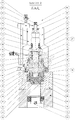
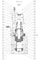
- FIGS. 1 to 5 a partially cutaway front view of an embodiment of a bolt-tensioning device according to the invention, shown in five steps when tightening a bolt.
- a bolt 21 two machine parts 90, 91 brace each other and therefore clamped with a bolt tensioning device 60.
- the bolt 21 and the bolt tensioning device 60 are first based on FIG. 1 described.
- the bolt 21 is recessed in the machine parts to be clamped 90, 91 with both the bolt head 23 and with the bolt end 24.
- the bolt head 23 has an external thread 25, onto which a nut 26 is screwed. The nut 26 abuts against the lower machine part 91 in the figures.
- the bolt end 24 has an external thread 18 and a thereto from the end face 27, i. the end face, from coaxially extending internal thread 20.
- these threads 18, 20 in the illustrated embodiment are independent of each other and can be optimally adapted to the respective requirements.
- the threads can also be conically shaped, for example.
- the bolt-tensioning device 60 has a cylinder 28 which has a support surface 30 for supporting on a machine part 90 on a first end face 29 and is covered on its second end face 31 by a cover 4.
- the cylinder 28 is formed from a first and a second cylinder section 13, 6, which along the cylinder axis 44 (FIG. FIG. 2 ) are arranged one behind the other.
- an outer exchange bushing 11 is arranged, which is rotatably and axially displaceably mounted relative to the cylinder 28.
- the outer exchange sleeve 11 protrudes with a first portion 32 radially inwardly of the annular support surface 30 from the first end face 29.
- the outer exchange bushing 11 has an internal thread 17, which is designed for screwing with the external thread 18 of the bolt end 24.
- the outer exchange bushing 11 protrudes by the amount of the support surface 30, which corresponds to the target Verschraubungs invented, so that upon reaching the desired Verschraubungs FREE the cylinder 28 rests with its support surface 30 on the machine part 90.
- An inner exchange bushing 2 passes through the cover 4 and the second cylinder section 6 and the axial through-hole 34 and protrudes with its first end from the axial through-hole 34 into the first section 32 of the outer exchange bushing 11.
- the inner exchange socket 2 has an external thread 35, which is designed for screwing with the internal thread 20 of the bolt end 24. With its second end, the inner exchange socket 2 protrudes from the cover 4 and forms a projection 42 there having a predetermined length.
- the inner exchange socket 2 is axially displaceable relative to the outer exchange bushing 11 and relative to the second cylinder section 6. In an axial displacement position, the inner exchange socket 2 with the outer exchange sleeve 11 is rotatably connected ( FIGS. 1 and 2 ); in the other displacement positions, the inner exchange socket 2 with respect to the outer exchange sleeve 11 is rotatable ( FIGS. 3 to 5 ).
- annular hexagonal adapter 8 which has at least two partial rings 36, 37 in the radial direction ( FIG. 3 ), which are mutually axially displaceable, but not rotatable.
- the outer part ring 36 is fixedly connected to the outer exchange socket 11.
- the inner part ring 37 encloses the inner exchange socket 2 and is firmly connected thereto. He 37 has on its radial outer side a profiling, which engages in a corresponding profiling of the outer part of ring 36 to prevent rotation of the inner exchange sleeve 2 relative to the outer exchange sleeve 11.
- a coil spring 9 which surrounds the inner exchange socket 2 and this in the direction away from the first end face 29 of the cylinder 28 direction, d. H. in the direction of the cover 4, biased against the outer exchange socket 11.
- This coil spring 9 encloses the inner exchange socket 2 on a longitudinal section and is received in a recess in the second section 33 of the outer exchange socket 11. The coil spring 9 abuts with its other end to the bottom of the recess.
- the two partial rings 36, 37 engage each other when the spring 9 is relaxed, d. H. in the initial state before screwing the inner exchange socket 2. In the initial state can thus be screwed onto the external thread 18 of the bolt end 24 by turning the inner exchange socket 2, the outer changeover bushing 11.
- the outer exchange bushing 11 is fixedly connected to a first annular piston 12, which surrounds it and is displaceable axially relative to the cylinder 28 by a hydraulic pressure medium in the direction away from the support surface 30 direction. With the first piston 12 and the outer exchange bushing 11 is moved. In the first cylinder section 13, a first pressure medium supply for the first piston 12 is formed.
- the inner exchange socket 2 is enclosed in the second cylinder section 6 by a second annular piston 7 and fixedly connected thereto.
- This second piston 7 is axially displaceable by pressure medium in the direction away from the support surface 30 direction, wherein displaced by moving the second piston 7 and the inner exchange socket 2 becomes.
- a second pressure medium supply for the second piston 7 is formed in the second cylinder section 6, a second pressure medium supply for the second piston 7 is formed.
- the effective piston areas of the first and second pistons 12, 7 have the same size ratio to one another as the shares of the total prestressing force to be transmitted by the two interchangeable bushes 11, 2.
- Both pressure medium feeders are connected to a common pressure medium connection 5, so that a pressurization and thus a displacement of the two pistons 12, 7 can be done exclusively together.
- the pressure medium connection 5 is a pressure medium distributor, which is provided with a connection nipple 10 for a high-pressure hose.
- a rotary sleeve 16 is disposed between the first cylinder portion 13 and the outer exchange sleeve 11, which is rotatable both with respect to the first cylinder portion 13 and with respect to the outer exchange sleeve 11.
- This rotary sleeve 16 has a first section 38, which is arranged within the first cylinder section 13 and is aligned with the support surface 30.
- a second portion 39 of the rotary sleeve 16 extends from the first portion 38 along the outside of the portion of the outer interchangeable sleeve 11, which projects beyond the support surface 30, and is connected to a third portion 40.
- the third portion 40 is also annular and with its radial inside a positive fit, d. H. rotatably, on the nut 22 can be applied, which is screwed onto the bolt end 24.
- the first portion 38 of the rotary sleeve 16 has an external toothing, which is in engagement with gears in a gear connection 14.
- the pressure medium connection 5 or distributor has a hydraulic safety valve 3, which can be actuated by an actuating element 41.
- the adjusting element 41 is formed in the illustrated embodiment as a pin which is displaceable in its longitudinal direction.
- the hydraulic valve 3 locks in a first valve position, the supply of the pressure medium supply with hydraulic pressure medium and are in a second valve position, this supply free. By moving the pin 41, the hydraulic valve 3 is transferred from one to the other valve position.
- the pin 41 extends parallel to the end face 43 of the lid 4 to the inner exchange socket 2, d. H. in the room, which can also be taken from the supernatant 42, so that in predetermined positions of the inner exchange socket 2 by the projection 42 of the pin 41 is moved.
- the pin 41 is spring-biased in the direction of the inner exchange socket 2 and displaceable by the supernatant 42 against the spring force.
- the length of the projection 42 in the non-screwed state of the inner exchange socket 2, d. H. with a relaxed spring 9 the sum of the desired screwing of the inner exchange socket 2 in the internal thread 20 of the bolt end 24 and the clearance between the inner exchange socket 2 and the bolt end 24 with screwed onto the bolt end 24 outer exchange socket 11th
- the clear distance is at least as large as the ring width of the annular hexagonal adapter 8, so that the inner exchange socket 2 can only be moved axially until it is freely rotatable relative to the outer exchange bush 11.
- the pin 41 of the hydraulic valve 3 extends in the illustrated embodiment, parallel to the end face 43 of the lid 4 and has a clear distance to this, which is less than the above protrusion length and at least as large as the desired elongation length of the screw bolt 21st ,
- the clearance is equal to the desired elongation length of the bolt 21, it is ensured on the one hand that the inner exchange bushing 2 is screwed in correctly when pressurized, ie has reached its desired screwing depth. This excludes that the thread can tear off. On the other hand, it is also ensured that the screw bolt 21 is not overstretched, since the projection 42 is exceeded when the set elongation length is exceeded far protrudes from the lid 4 that it engages with the pin 41 of the hydraulic valve 3 and moves it. The hydraulic valve 3 would thereby transferred to the first valve position, in which it blocks the supply of the pressure medium feeds.
- a bolt 21 is made, which has an external thread 18 and an internal thread 20 at its bolt end 24.
- This bolt 21 is guided through the through holes in the machine parts 90, 91 to be clamped together.
- the bolt head 23 is also provided with an external thread 25, so that screwed onto the bolt head 23 and on the bolt end 24, the corresponding nuts 26, 22 and attached to the machine parts 91, 90, without the screw on the bolt 21, a biasing force is applied.
- the bolt-tensioning device 60 is attached to the bolt end 24 so that the outer removable bushing 11 and - in the case of a sunk arranged nut 22 - and the rotary sleeve 16 abuts the thread beginning. That is, the cylinder axis 44 of the bolt tensioner is aligned with the bolt axis.
- the pin 41 of the hydraulic valve 3 is displaced by the projection 42 of the inner exchange socket 2 and the valve 3 thus in the first valve position in which it blocks the supply of the pressure medium supply with pressure medium.
- the inner exchange sleeve 2 is screwed into the internal thread 20 of the bolt end 24, wherein upon reaching the desired screwing the free end of the supernatant 42 with the end face 43 of the lid 4 is aligned ( FIG. 3 ).
- the pin 41 of the hydraulic valve 3 is no longer displaced by the projection 42. The valve 3 is thus in the second valve position, in which it releases the supply of the pressure medium supply with pressure medium.
- the first and the second piston 12, 7 together pressure medium supplied, so that they move axially in the direction away from the support surface 30 direction while taking the outer and the inner exchange socket 11, 2.
- the total biasing force is thereby divided between the female thread 20 and the male thread 18 of the bolt end. According to the applied total biasing force, the bolt 21 (FIGS. FIG. 4 ).
- the nut 22 Upon reaching the desired elongation or the target total prestressing force, the nut 22 is screwed in at the bolt end 24 until it rests against the machine part 90 with the aid of the rotary sleeve 16 ( FIG. 5 ).
- the bolt-tensioning device 60 is relieved by the pressure medium is discharged again.
- the inner exchange socket 2 can be unscrewed from the bolt end 24 and is pressed by its spring bias 9 back to its original position.
- the outer exchange bushing 11 is unscrewed from the bolt end 24. By a spring bias and the outer exchange sleeve 11 is pressed back into its original position.
- the bolt tensioner 60 can be removed.
Landscapes
- Engineering & Computer Science (AREA)
- Mechanical Engineering (AREA)
- General Engineering & Computer Science (AREA)
- Hand Tools For Fitting Together And Separating, Or Other Hand Tools (AREA)
Claims (7)
- Dispositif hydraulique de serrage de boulon pour serrer des boulons (21) qui traversent des pièces de machine (90, 91) à serrer entre elles et qui présentent une tête de boulon (23) appuyée sur un côté des pièces de machine (91) et qui présentent une extrémité de boulon (24) prévue pour le boulonnage avec le dispositif de serrage de boulon (60), l'extrémité de boulon (24) présentant un filetage (18) et au moins un taraudage (20) qui s'étend depuis le côté frontal (27) le long de l'axe de boulon, comportant- un cylindre (28) ayant un axe de cylindre (44) et présentant sur un premier côté frontal (29) une surface d'appui (30) pour s'appuyer sur les pièces de machine (90),- une douille interchangeable extérieure (11) qui est agencée dans le cylindre (28) de façon mobile en translation axiale par rapport à celui-ci et qui présente une première portion (32) pourvue d'un taraudage (17) pour le boulonnage sur le filetage (18) de l'extrémité de boulon (24) et une seconde portion (33) pourvue d'un perçage traversant axial (34) débouchant dans la première portion (32),- une douille interchangeable intérieure (2) qui traverse le cylindre (28) et le perçage traversant (34) de la douille interchangeable extérieure (11) et qui est mobile en rotation et en translation axiale par rapport à ceux-ci et qui présente un filetage (35) à une première extrémité, qui est susceptible d'être boulonné dans le taraudage (20) de l'extrémité de boulon (24),- un premier piston (12) qui est relié solidairement à la douille interchangeable extérieure (11) et qui est mobile en translation axiale dans le cylindre (28) dans la direction détournée de la surface d'appui (30) par des agents sous pression, le cylindre (28) présentant une première alimentation en agent sous pression,- un second piston (7) qui est relié solidairement à la douille interchangeable intérieure (2) et qui est mobile en translation axiale dans le cylindre (28) dans la direction détournée de la surface d'appui (30) par un agent sous pression, le cylindre (28) présentant une seconde alimentation en agent sous pression,- le rapport proportionnel des surfaces actives des premier et second pistons (12, 7) l'une par rapport à l'autre correspondant au rapport proportionnel entre les parts de la précontrainte totale à transmettre depuis la douille interchangeable extérieure (11) et la douille interchangeable intérieure (2),- un raccord d'agent sous pression (5) qui est en liaison fluidique avec la première et avec la seconde alimentation en agent sous pression.
- Dispositif de serrage de boulon selon la revendication 1, caractérisé en ce que la douille interchangeable intérieure (2) est précontrainte par un ressort par rapport à la douille interchangeable extérieure (11) dans la direction détournée de la surface d'appui (30).
- Dispositif de serrage de boulon selon la revendication 2, caractérisé en ce que dans l'état détendu du ressort (9), la seconde extrémité de la douille interchangeable intérieure (2) dépasse d'une longueur donnée au-delà d'un couvercle (4) du dispositif de serrage de boulon (60) qui est monté sur l'autre second côté frontal (31) du cylindre (28), la course du ressort étant aussi importante que la douille interchangeable intérieure (2) est mobile en translation d'une valeur donnée avant le boulonnage dans l'extrémité de boulon (24).
- Dispositif de serrage de boulon selon la revendication 3, caractérisé en ce que la longueur de dépassement est égale à la somme de la distance libre entre la douille interchangeable intérieure (2) et l'extrémité de boulon (24), dans l'état boulonné de la douille interchangeable extérieure (11), et de la profondeur de boulonnage minimale de la douille interchangeable intérieure (2) dans le taraudage (20) de l'extrémité de boulon (24).
- Dispositif de serrage de boulon selon la revendication 3 ou 4, caractérisé par une valve hydraulique (3) qui peut être transférée depuis une première position de valve dans laquelle elle bloque l'alimentation en agent sous pression des admissions d'agent sous pression, jusque dans une seconde position de valve dans laquelle elle libère cette alimentation, et en retour, par un élément de positionnement (41) qui peut être actionné par la douille interchangeable intérieure (2) dans des positions données de celle-ci.
- Dispositif de serrage de boulon selon les revendications 4 et 5, caractérisé en ce que l'élément de positionnement (41)- s'étend parallèlement au côté frontal (43) du couvercle (4) à une distance libre par rapport à celui-ci qui est inférieure à la longueur de dépassement selon la revendication 4 et qui est au moins aussi grande que la longueur d'extension de consigne du boulon (21),- est précontraint élastiquement vers la douille interchangeable intérieure (2),- est mobile depuis la douille interchangeable intérieure (2) à l'encontre de la force élastique lorsque le dépassement (42) est supérieur à la distance libre, et- transfère la valve (3) jusque dans la première position de valve, dans l'état translaté, et la transfère jusque dans la seconde position de valve, dans l'état non translaté.
- Dispositif hydraulique de serrage de boulon pour serrer des boulons (21) qui traversent des pièces de machine (90, 91) à serrer entre elles et qui présentent une tête de boulon (23) appuyée sur un côté des pièces de machine (91) et qui présentent une extrémité de boulon (24) prévue pour le boulonnage avec le dispositif de serrage de boulon (60), l'extrémité de boulon (24) présentant un filetage (18) et un seul taraudage (20) qui s'étend depuis le côté frontal (27) le long de l'axe de boulon et coaxialement au filetage, comportant- un cylindre ayant un axe de cylindre et présentant sur un premier côté frontal une surface d'appui pour s'appuyer sur les pièces de machine,- une douille interchangeable qui est agencée dans le cylindre de façon mobile en translation axiale par rapport à celui-ci et qui présente un taraudage pour le boulonnage sur le filetage de l'extrémité de boulon ainsi qu'une tige centrale pourvue d'un filetage et reliée d'un seul tenant au taraudage, ledit filetage pouvant être boulonné dans le taraudage de l'extrémité de boulon, le taraudage et le filetage étant réalisés de manière à tourner dans le même sens et étant adaptés l'un à l'autre de telle sorte que la douille interchangeable peut être boulonnée à la fois avec un filetage et avec un taraudage de l'extrémité de boulon réalisés en correspondance et adaptés l'un à l'autre,- un piston qui est relié solidairement à la douille interchangeable et qui est mobile en translation axiale dans le cylindre dans la direction détournée de la surface d'appui par un agent sous pression, le cylindre présentant une alimentation en agent sous pression, et- un raccord d'agent sous pression qui est en liaison fluidique avec l'alimentation en agent sous pression.
Applications Claiming Priority (2)
| Application Number | Priority Date | Filing Date | Title |
|---|---|---|---|
| DE102010006562A DE102010006562B4 (de) | 2010-02-02 | 2010-02-02 | Verfahren zum Spannen von Schraubenbolzen, sowie Schraubenbolzen und Schraubenbolzen-Spannvorrichtung zur Durchführung des Verfahrens |
| EP11000321.7A EP2353773B1 (fr) | 2010-02-02 | 2011-01-17 | Joint à vis avec un boulon ainsi qu' un dispositif de mise en tension de boulons |
Related Parent Applications (2)
| Application Number | Title | Priority Date | Filing Date |
|---|---|---|---|
| EP11000321.7A Division EP2353773B1 (fr) | 2010-02-02 | 2011-01-17 | Joint à vis avec un boulon ainsi qu' un dispositif de mise en tension de boulons |
| EP11000321.7A Division-Into EP2353773B1 (fr) | 2010-02-02 | 2011-01-17 | Joint à vis avec un boulon ainsi qu' un dispositif de mise en tension de boulons |
Publications (2)
| Publication Number | Publication Date |
|---|---|
| EP2910331A1 EP2910331A1 (fr) | 2015-08-26 |
| EP2910331B1 true EP2910331B1 (fr) | 2018-07-11 |
Family
ID=43595170
Family Applications (2)
| Application Number | Title | Priority Date | Filing Date |
|---|---|---|---|
| EP15000386.1A Active EP2910331B1 (fr) | 2010-02-02 | 2011-01-17 | Dispositif de serrage de boulons hydraulique |
| EP11000321.7A Active EP2353773B1 (fr) | 2010-02-02 | 2011-01-17 | Joint à vis avec un boulon ainsi qu' un dispositif de mise en tension de boulons |
Family Applications After (1)
| Application Number | Title | Priority Date | Filing Date |
|---|---|---|---|
| EP11000321.7A Active EP2353773B1 (fr) | 2010-02-02 | 2011-01-17 | Joint à vis avec un boulon ainsi qu' un dispositif de mise en tension de boulons |
Country Status (4)
| Country | Link |
|---|---|
| US (1) | US8616094B2 (fr) |
| EP (2) | EP2910331B1 (fr) |
| JP (1) | JP5284381B2 (fr) |
| DE (1) | DE102010006562B4 (fr) |
Families Citing this family (14)
| Publication number | Priority date | Publication date | Assignee | Title |
|---|---|---|---|---|
| KR101205990B1 (ko) * | 2004-06-17 | 2012-11-29 | 존 웬트워드 버크넬 | 볼트 텐셔닝 장치 및 방법 |
| US20110271798A1 (en) * | 2008-11-14 | 2011-11-10 | Wagner Vermogensverwaltungs- GMBH & Co.KG | Screw tensioning device |
| GB2474887B (en) * | 2009-10-30 | 2013-12-04 | Stats Uk Ltd | Device and method for pre-tensioning a coupling |
| US20130008015A1 (en) * | 2010-02-08 | 2013-01-10 | Junkers John K | Apparatus and methods for tightening threaded fasteners |
| DE102013107096A1 (de) * | 2013-07-05 | 2015-01-08 | Ith Gmbh & Co. Kg | Spannvorrichtung zum Dehnen eines Gewindebolzens |
| DE102015104133A1 (de) | 2015-03-19 | 2016-09-22 | Frank Hohmann | Spannvorrichtung zum Dehnen eines Gewindebolzens |
| CN107717429A (zh) * | 2017-11-09 | 2018-02-23 | 大连泰凯工业有限公司 | 用于风力发电机轮毂主螺栓的多级超高压薄壁液压拉伸器 |
| DE102018107657A1 (de) * | 2018-03-29 | 2019-10-02 | Frank Hohmann | Vorrichtung zum Anziehen von Schraubverbindungen |
| EP4126459A1 (fr) | 2020-03-25 | 2023-02-08 | Milwaukee Electric Tool Corporation | Outil de serrage de boulon |
| CN113664485B (zh) * | 2020-05-15 | 2022-11-01 | 国核电站运行服务技术有限公司 | 一种核电爆破阀中阀盖和活塞的装配装置 |
| CN112392822B (zh) * | 2020-11-10 | 2022-05-10 | 无锡鸿海龙船机有限公司 | 一种新型液压螺栓 |
| CN112692561B (zh) * | 2021-01-26 | 2023-02-07 | 江苏格纳特连接系统有限公司 | 一种高稳定性顶推装置 |
| CN113909838A (zh) * | 2021-10-09 | 2022-01-11 | 浙江海格威液压科技有限公司 | 一种液压管接头穿丝设备 |
| US12553550B2 (en) * | 2021-11-15 | 2026-02-17 | Spm Oil & Gas Inc. | Tensioner and method of using same |
Family Cites Families (19)
| Publication number | Priority date | Publication date | Assignee | Title |
|---|---|---|---|---|
| US2866370A (en) * | 1956-02-02 | 1958-12-30 | John L Biach | Bolt-tensioning and nut-seating apparatus |
| US3015975A (en) * | 1959-11-17 | 1962-01-09 | Biach Ind | Bolt-tensioning apparatus |
| DE3271024D1 (en) * | 1981-11-27 | 1986-06-12 | Bbc Brown Boveri & Cie | Device to prestress a bolt |
| US4844418A (en) * | 1987-03-02 | 1989-07-04 | Westinghouse Electric Corp. | Short stud tensioning apparatus |
| US5253967A (en) * | 1991-11-08 | 1993-10-19 | Biach Industries | Adapter assembly for tensioning threaded fasteners and method of tensioning threaded fasteners |
| DE4313778A1 (de) * | 1993-04-27 | 1994-11-03 | Westfalia Becorit Ind Tech | Schraubenspannvorrichtung |
| ATE153583T1 (de) | 1993-12-08 | 1997-06-15 | Frank Hohmann | Hydraulische gewindebolzenspannvorrichtung |
| SE9502130L (sv) * | 1995-06-13 | 1996-12-14 | Ovako Couplings Ab | Förspänning av casing-bultar |
| EP0797012A3 (fr) * | 1996-03-20 | 1998-08-26 | Hydra-Tight Limited | Tendeur à commande hydraulique |
| US6077008A (en) | 1996-04-16 | 2000-06-20 | Ovaka Couplings Ab | Safety device for preloaded bolts |
| DE19638901C2 (de) | 1996-09-23 | 2000-05-25 | Joerg Hohmann | Hydraulische Gewindebolzenspannvorrichtung |
| US5956917A (en) * | 1997-01-09 | 1999-09-28 | Reynolds; Glenn A. | Co-axial joint system |
| AUPP890599A0 (en) * | 1999-02-26 | 1999-03-25 | Bucknell, John Wentworth | Tensioning hydraulic nuts |
| DE10143406A1 (de) * | 2001-09-05 | 2003-04-03 | Schott Glas | Feineinstellvorrichtung zur Einstellung des Abstandes zwischen zwei betrieblich mit ihr verbundenen Maschinenbauelementen |
| DE10145847C2 (de) | 2001-09-17 | 2003-09-18 | Joerg Hohmann | Hydraulische Gewindebolzenspannvorrichtung und Verfahren zum Anziehen von grossen Schrauben mittels der hydraulischen Gewindebolzenspannvorrichtung |
| KR101205990B1 (ko) * | 2004-06-17 | 2012-11-29 | 존 웬트워드 버크넬 | 볼트 텐셔닝 장치 및 방법 |
| DE102004043146B3 (de) | 2004-09-03 | 2005-11-24 | Hohmann, Jörg | Hydraulische Schraubenspannvorrichtung |
| DE102004043145B3 (de) | 2004-09-03 | 2006-05-18 | Hohmann, Jörg | Hydraulische Schraubenspannvorrichtung |
| DE102005015922B4 (de) | 2005-04-06 | 2007-08-02 | Hohmann, Jörg | Hydraulische Gewindebolzenspannvorrichtung und Verfahren zum Anziehen von großen Schrauben mittels der hydraulischen Gewindebolzenspannvorrichtung |
-
2010
- 2010-02-02 DE DE102010006562A patent/DE102010006562B4/de active Active
-
2011
- 2011-01-17 EP EP15000386.1A patent/EP2910331B1/fr active Active
- 2011-01-17 EP EP11000321.7A patent/EP2353773B1/fr active Active
- 2011-01-25 US US13/013,574 patent/US8616094B2/en active Active
- 2011-01-31 JP JP2011018568A patent/JP5284381B2/ja active Active
Non-Patent Citations (1)
| Title |
|---|
| None * |
Also Published As
| Publication number | Publication date |
|---|---|
| US20110188960A1 (en) | 2011-08-04 |
| JP5284381B2 (ja) | 2013-09-11 |
| EP2910331A1 (fr) | 2015-08-26 |
| JP2011158092A (ja) | 2011-08-18 |
| EP2353773A1 (fr) | 2011-08-10 |
| US8616094B2 (en) | 2013-12-31 |
| DE102010006562B4 (de) | 2011-11-10 |
| DE102010006562A1 (de) | 2011-08-04 |
| EP2353773B1 (fr) | 2015-09-16 |
Similar Documents
| Publication | Publication Date | Title |
|---|---|---|
| EP2353773B1 (fr) | Joint à vis avec un boulon ainsi qu' un dispositif de mise en tension de boulons | |
| EP3069827B1 (fr) | Dispositif de serrage pour l'etirement d'un boulon filete | |
| DE102013003053B4 (de) | Spannvorrichtung sowie Verfahren zum Spannen von Werkstücken mit axial verschiebbarer Spannschraube in axial verschiebbarem Stößel | |
| EP0271864A2 (fr) | Mécanisme d'actionnement à réajustage automatique pour freins, en particulier pour véhicules poids lourd | |
| EP1698436A1 (fr) | Dispositif pour l'insertion et l'extraction d'un palier de roue fermé sur sa face arrière | |
| CH619629A5 (fr) | ||
| DE102010048068B4 (de) | Ventilanordnung | |
| EP0751059B1 (fr) | Procédé et dispositif de montage pour soupape de direction assistée | |
| EP0416610B1 (fr) | Porte-outil, notamment pour tours, avec porte-outil interchangeable | |
| EP2181839B1 (fr) | Poinçon pour une presse rotative | |
| DE102011086853A1 (de) | Nullpunktspannsystem | |
| EP3043954B1 (fr) | Dispositif de serrage d'au moins un téton de serrage | |
| EP3755497B1 (fr) | Outil à vis multiples | |
| DE102019108382B4 (de) | Gehäuseoberteil für Hochdruckfilter und Hochdruckfilter | |
| DE69820360T2 (de) | Hydraulikpumpenanlage | |
| EP3755495B1 (fr) | Outil de vissage multiple | |
| EP3755496B1 (fr) | Outil de vissage polyvalent | |
| DE20110168U1 (de) | Werkzeugwechselvorrichtung | |
| WO2000074869A1 (fr) | Systeme pour changer l'ecrou maintenant un cylindre de laminage | |
| DE102004036868B4 (de) | Heizkreisverteiler mit gewindelosen Anschlussstutzen | |
| DE102019218402B4 (de) | Federdom für ein Hydraulikventil und Hydraulikventil mit einem solchen Federdom | |
| EP3537017A1 (fr) | Soupape | |
| DE3811776A1 (de) | Hydraulischer kraftschrauber | |
| DE10004670B4 (de) | Druckabschalteinrichtung für eine Hilfskraftlenkung in den Endstellungen des Lenkausschlages | |
| EP3184819A2 (fr) | Procede d'etancheification de deux parois de separation et etancheite de paroi de separation |
Legal Events
| Date | Code | Title | Description |
|---|---|---|---|
| PUAI | Public reference made under article 153(3) epc to a published international application that has entered the european phase |
Free format text: ORIGINAL CODE: 0009012 |
|
| AC | Divisional application: reference to earlier application |
Ref document number: 2353773 Country of ref document: EP Kind code of ref document: P |
|
| AK | Designated contracting states |
Kind code of ref document: A1 Designated state(s): AL AT BE BG CH CY CZ DE DK EE ES FI FR GB GR HR HU IE IS IT LI LT LU LV MC MK MT NL NO PL PT RO RS SE SI SK SM TR |
|
| 17P | Request for examination filed |
Effective date: 20160115 |
|
| RBV | Designated contracting states (corrected) |
Designated state(s): AL AT BE BG CH CY CZ DE DK EE ES FI FR GB GR HR HU IE IS IT LI LT LU LV MC MK MT NL NO PL PT RO RS SE SI SK SM TR |
|
| GRAP | Despatch of communication of intention to grant a patent |
Free format text: ORIGINAL CODE: EPIDOSNIGR1 |
|
| STAA | Information on the status of an ep patent application or granted ep patent |
Free format text: STATUS: GRANT OF PATENT IS INTENDED |
|
| RIC1 | Information provided on ipc code assigned before grant |
Ipc: B25B 29/02 20060101ALI20180105BHEP Ipc: F16B 31/04 20060101ALN20180105BHEP Ipc: B23P 19/06 20060101AFI20180105BHEP |
|
| INTG | Intention to grant announced |
Effective date: 20180201 |
|
| GRAA | (expected) grant |
Free format text: ORIGINAL CODE: 0009210 |
|
| STAA | Information on the status of an ep patent application or granted ep patent |
Free format text: STATUS: THE PATENT HAS BEEN GRANTED |
|
| AC | Divisional application: reference to earlier application |
Ref document number: 2353773 Country of ref document: EP Kind code of ref document: P |
|
| AK | Designated contracting states |
Kind code of ref document: B1 Designated state(s): AL AT BE BG CH CY CZ DE DK EE ES FI FR GB GR HR HU IE IS IT LI LT LU LV MC MK MT NL NO PL PT RO RS SE SI SK SM TR |
|
| REG | Reference to a national code |
Ref country code: GB Ref legal event code: FG4D Free format text: NOT ENGLISH |
|
| REG | Reference to a national code |
Ref country code: CH Ref legal event code: EP |
|
| REG | Reference to a national code |
Ref country code: AT Ref legal event code: REF Ref document number: 1016390 Country of ref document: AT Kind code of ref document: T Effective date: 20180715 |
|
| GRAS | Grant fee paid |
Free format text: ORIGINAL CODE: EPIDOSNIGR3 |
|
| REG | Reference to a national code |
Ref country code: DE Ref legal event code: R096 Ref document number: 502011014455 Country of ref document: DE |
|
| REG | Reference to a national code |
Ref country code: IE Ref legal event code: FG4D Free format text: LANGUAGE OF EP DOCUMENT: GERMAN |
|
| REG | Reference to a national code |
Ref country code: NL Ref legal event code: MP Effective date: 20180711 |
|
| REG | Reference to a national code |
Ref country code: LT Ref legal event code: MG4D |
|
| PG25 | Lapsed in a contracting state [announced via postgrant information from national office to epo] |
Ref country code: NL Free format text: LAPSE BECAUSE OF FAILURE TO SUBMIT A TRANSLATION OF THE DESCRIPTION OR TO PAY THE FEE WITHIN THE PRESCRIBED TIME-LIMIT Effective date: 20180711 |
|
| PG25 | Lapsed in a contracting state [announced via postgrant information from national office to epo] |
Ref country code: BG Free format text: LAPSE BECAUSE OF FAILURE TO SUBMIT A TRANSLATION OF THE DESCRIPTION OR TO PAY THE FEE WITHIN THE PRESCRIBED TIME-LIMIT Effective date: 20181011 Ref country code: PL Free format text: LAPSE BECAUSE OF FAILURE TO SUBMIT A TRANSLATION OF THE DESCRIPTION OR TO PAY THE FEE WITHIN THE PRESCRIBED TIME-LIMIT Effective date: 20180711 Ref country code: LT Free format text: LAPSE BECAUSE OF FAILURE TO SUBMIT A TRANSLATION OF THE DESCRIPTION OR TO PAY THE FEE WITHIN THE PRESCRIBED TIME-LIMIT Effective date: 20180711 Ref country code: RS Free format text: LAPSE BECAUSE OF FAILURE TO SUBMIT A TRANSLATION OF THE DESCRIPTION OR TO PAY THE FEE WITHIN THE PRESCRIBED TIME-LIMIT Effective date: 20180711 Ref country code: IS Free format text: LAPSE BECAUSE OF FAILURE TO SUBMIT A TRANSLATION OF THE DESCRIPTION OR TO PAY THE FEE WITHIN THE PRESCRIBED TIME-LIMIT Effective date: 20181111 Ref country code: FI Free format text: LAPSE BECAUSE OF FAILURE TO SUBMIT A TRANSLATION OF THE DESCRIPTION OR TO PAY THE FEE WITHIN THE PRESCRIBED TIME-LIMIT Effective date: 20180711 Ref country code: NO Free format text: LAPSE BECAUSE OF FAILURE TO SUBMIT A TRANSLATION OF THE DESCRIPTION OR TO PAY THE FEE WITHIN THE PRESCRIBED TIME-LIMIT Effective date: 20181011 Ref country code: GR Free format text: LAPSE BECAUSE OF FAILURE TO SUBMIT A TRANSLATION OF THE DESCRIPTION OR TO PAY THE FEE WITHIN THE PRESCRIBED TIME-LIMIT Effective date: 20181012 Ref country code: SE Free format text: LAPSE BECAUSE OF FAILURE TO SUBMIT A TRANSLATION OF THE DESCRIPTION OR TO PAY THE FEE WITHIN THE PRESCRIBED TIME-LIMIT Effective date: 20180711 |
|
| PG25 | Lapsed in a contracting state [announced via postgrant information from national office to epo] |
Ref country code: HR Free format text: LAPSE BECAUSE OF FAILURE TO SUBMIT A TRANSLATION OF THE DESCRIPTION OR TO PAY THE FEE WITHIN THE PRESCRIBED TIME-LIMIT Effective date: 20180711 Ref country code: ES Free format text: LAPSE BECAUSE OF FAILURE TO SUBMIT A TRANSLATION OF THE DESCRIPTION OR TO PAY THE FEE WITHIN THE PRESCRIBED TIME-LIMIT Effective date: 20180711 Ref country code: AL Free format text: LAPSE BECAUSE OF FAILURE TO SUBMIT A TRANSLATION OF THE DESCRIPTION OR TO PAY THE FEE WITHIN THE PRESCRIBED TIME-LIMIT Effective date: 20180711 Ref country code: LV Free format text: LAPSE BECAUSE OF FAILURE TO SUBMIT A TRANSLATION OF THE DESCRIPTION OR TO PAY THE FEE WITHIN THE PRESCRIBED TIME-LIMIT Effective date: 20180711 |
|
| REG | Reference to a national code |
Ref country code: DE Ref legal event code: R097 Ref document number: 502011014455 Country of ref document: DE |
|
| PG25 | Lapsed in a contracting state [announced via postgrant information from national office to epo] |
Ref country code: EE Free format text: LAPSE BECAUSE OF FAILURE TO SUBMIT A TRANSLATION OF THE DESCRIPTION OR TO PAY THE FEE WITHIN THE PRESCRIBED TIME-LIMIT Effective date: 20180711 Ref country code: IT Free format text: LAPSE BECAUSE OF FAILURE TO SUBMIT A TRANSLATION OF THE DESCRIPTION OR TO PAY THE FEE WITHIN THE PRESCRIBED TIME-LIMIT Effective date: 20180711 Ref country code: CZ Free format text: LAPSE BECAUSE OF FAILURE TO SUBMIT A TRANSLATION OF THE DESCRIPTION OR TO PAY THE FEE WITHIN THE PRESCRIBED TIME-LIMIT Effective date: 20180711 Ref country code: RO Free format text: LAPSE BECAUSE OF FAILURE TO SUBMIT A TRANSLATION OF THE DESCRIPTION OR TO PAY THE FEE WITHIN THE PRESCRIBED TIME-LIMIT Effective date: 20180711 |
|
| PLBE | No opposition filed within time limit |
Free format text: ORIGINAL CODE: 0009261 |
|
| STAA | Information on the status of an ep patent application or granted ep patent |
Free format text: STATUS: NO OPPOSITION FILED WITHIN TIME LIMIT |
|
| PG25 | Lapsed in a contracting state [announced via postgrant information from national office to epo] |
Ref country code: SM Free format text: LAPSE BECAUSE OF FAILURE TO SUBMIT A TRANSLATION OF THE DESCRIPTION OR TO PAY THE FEE WITHIN THE PRESCRIBED TIME-LIMIT Effective date: 20180711 Ref country code: DK Free format text: LAPSE BECAUSE OF FAILURE TO SUBMIT A TRANSLATION OF THE DESCRIPTION OR TO PAY THE FEE WITHIN THE PRESCRIBED TIME-LIMIT Effective date: 20180711 Ref country code: SK Free format text: LAPSE BECAUSE OF FAILURE TO SUBMIT A TRANSLATION OF THE DESCRIPTION OR TO PAY THE FEE WITHIN THE PRESCRIBED TIME-LIMIT Effective date: 20180711 |
|
| 26N | No opposition filed |
Effective date: 20190412 |
|
| PG25 | Lapsed in a contracting state [announced via postgrant information from national office to epo] |
Ref country code: SI Free format text: LAPSE BECAUSE OF FAILURE TO SUBMIT A TRANSLATION OF THE DESCRIPTION OR TO PAY THE FEE WITHIN THE PRESCRIBED TIME-LIMIT Effective date: 20180711 Ref country code: MC Free format text: LAPSE BECAUSE OF FAILURE TO SUBMIT A TRANSLATION OF THE DESCRIPTION OR TO PAY THE FEE WITHIN THE PRESCRIBED TIME-LIMIT Effective date: 20180711 |
|
| REG | Reference to a national code |
Ref country code: CH Ref legal event code: PL |
|
| PG25 | Lapsed in a contracting state [announced via postgrant information from national office to epo] |
Ref country code: LU Free format text: LAPSE BECAUSE OF NON-PAYMENT OF DUE FEES Effective date: 20190117 |
|
| REG | Reference to a national code |
Ref country code: BE Ref legal event code: MM Effective date: 20190131 |
|
| REG | Reference to a national code |
Ref country code: IE Ref legal event code: MM4A |
|
| PG25 | Lapsed in a contracting state [announced via postgrant information from national office to epo] |
Ref country code: BE Free format text: LAPSE BECAUSE OF NON-PAYMENT OF DUE FEES Effective date: 20190131 |
|
| PG25 | Lapsed in a contracting state [announced via postgrant information from national office to epo] |
Ref country code: LI Free format text: LAPSE BECAUSE OF NON-PAYMENT OF DUE FEES Effective date: 20190131 Ref country code: CH Free format text: LAPSE BECAUSE OF NON-PAYMENT OF DUE FEES Effective date: 20190131 |
|
| PG25 | Lapsed in a contracting state [announced via postgrant information from national office to epo] |
Ref country code: IE Free format text: LAPSE BECAUSE OF NON-PAYMENT OF DUE FEES Effective date: 20190117 |
|
| REG | Reference to a national code |
Ref country code: AT Ref legal event code: MM01 Ref document number: 1016390 Country of ref document: AT Kind code of ref document: T Effective date: 20190117 |
|
| PG25 | Lapsed in a contracting state [announced via postgrant information from national office to epo] |
Ref country code: TR Free format text: LAPSE BECAUSE OF FAILURE TO SUBMIT A TRANSLATION OF THE DESCRIPTION OR TO PAY THE FEE WITHIN THE PRESCRIBED TIME-LIMIT Effective date: 20180711 |
|
| PG25 | Lapsed in a contracting state [announced via postgrant information from national office to epo] |
Ref country code: AT Free format text: LAPSE BECAUSE OF NON-PAYMENT OF DUE FEES Effective date: 20190117 |
|
| PG25 | Lapsed in a contracting state [announced via postgrant information from national office to epo] |
Ref country code: MT Free format text: LAPSE BECAUSE OF FAILURE TO SUBMIT A TRANSLATION OF THE DESCRIPTION OR TO PAY THE FEE WITHIN THE PRESCRIBED TIME-LIMIT Effective date: 20180711 Ref country code: PT Free format text: LAPSE BECAUSE OF FAILURE TO SUBMIT A TRANSLATION OF THE DESCRIPTION OR TO PAY THE FEE WITHIN THE PRESCRIBED TIME-LIMIT Effective date: 20181111 |
|
| PG25 | Lapsed in a contracting state [announced via postgrant information from national office to epo] |
Ref country code: CY Free format text: LAPSE BECAUSE OF FAILURE TO SUBMIT A TRANSLATION OF THE DESCRIPTION OR TO PAY THE FEE WITHIN THE PRESCRIBED TIME-LIMIT Effective date: 20180711 |
|
| PG25 | Lapsed in a contracting state [announced via postgrant information from national office to epo] |
Ref country code: HU Free format text: LAPSE BECAUSE OF FAILURE TO SUBMIT A TRANSLATION OF THE DESCRIPTION OR TO PAY THE FEE WITHIN THE PRESCRIBED TIME-LIMIT; INVALID AB INITIO Effective date: 20110117 |
|
| PG25 | Lapsed in a contracting state [announced via postgrant information from national office to epo] |
Ref country code: MK Free format text: LAPSE BECAUSE OF FAILURE TO SUBMIT A TRANSLATION OF THE DESCRIPTION OR TO PAY THE FEE WITHIN THE PRESCRIBED TIME-LIMIT Effective date: 20180711 |
|
| P01 | Opt-out of the competence of the unified patent court (upc) registered |
Effective date: 20230513 |
|
| REG | Reference to a national code |
Ref country code: DE Ref legal event code: R082 Ref document number: 502011014455 Country of ref document: DE Representative=s name: ALPSPITZ IP ALLGAYER UND PARTNER PATENTANWAELT, DE |
|
| PGFP | Annual fee paid to national office [announced via postgrant information from national office to epo] |
Ref country code: GB Payment date: 20260123 Year of fee payment: 16 |
|
| PGFP | Annual fee paid to national office [announced via postgrant information from national office to epo] |
Ref country code: DE Payment date: 20260121 Year of fee payment: 16 |
|
| PGFP | Annual fee paid to national office [announced via postgrant information from national office to epo] |
Ref country code: FR Payment date: 20260123 Year of fee payment: 16 |