EP2910513A1 - Hebevorrichtung mit einer Regulierung der Höhenlage - Google Patents
Hebevorrichtung mit einer Regulierung der Höhenlage Download PDFInfo
- Publication number
- EP2910513A1 EP2910513A1 EP15155725.3A EP15155725A EP2910513A1 EP 2910513 A1 EP2910513 A1 EP 2910513A1 EP 15155725 A EP15155725 A EP 15155725A EP 2910513 A1 EP2910513 A1 EP 2910513A1
- Authority
- EP
- European Patent Office
- Prior art keywords
- frame
- lifting
- gear
- lifting apparatus
- relative
- Prior art date
- Legal status (The legal status is an assumption and is not a legal conclusion. Google has not performed a legal analysis and makes no representation as to the accuracy of the status listed.)
- Withdrawn
Links
- 230000001105 regulatory effect Effects 0.000 title 1
- 230000000087 stabilizing effect Effects 0.000 claims description 15
- 239000003381 stabilizer Substances 0.000 claims 1
- 238000006073 displacement reaction Methods 0.000 description 6
- 230000006378 damage Effects 0.000 description 2
- 208000027418 Wounds and injury Diseases 0.000 description 1
- 238000010276 construction Methods 0.000 description 1
- 238000001514 detection method Methods 0.000 description 1
- 230000005484 gravity Effects 0.000 description 1
- 208000014674 injury Diseases 0.000 description 1
- 230000001788 irregular Effects 0.000 description 1
- 238000012986 modification Methods 0.000 description 1
- 230000004048 modification Effects 0.000 description 1
- 238000011084 recovery Methods 0.000 description 1
- 238000006467 substitution reaction Methods 0.000 description 1
Images



Classifications
-
- B—PERFORMING OPERATIONS; TRANSPORTING
- B66—HOISTING; LIFTING; HAULING
- B66C—CRANES; LOAD-ENGAGING ELEMENTS OR DEVICES FOR CRANES, CAPSTANS, WINCHES, OR TACKLES
- B66C23/00—Cranes comprising essentially a beam, boom, or triangular structure acting as a cantilever and mounted for translatory of swinging movements in vertical or horizontal planes or a combination of such movements, e.g. jib-cranes, derricks, tower cranes
- B66C23/18—Cranes comprising essentially a beam, boom, or triangular structure acting as a cantilever and mounted for translatory of swinging movements in vertical or horizontal planes or a combination of such movements, e.g. jib-cranes, derricks, tower cranes specially adapted for use in particular purposes
- B66C23/36—Cranes comprising essentially a beam, boom, or triangular structure acting as a cantilever and mounted for translatory of swinging movements in vertical or horizontal planes or a combination of such movements, e.g. jib-cranes, derricks, tower cranes specially adapted for use in particular purposes mounted on road or rail vehicles; Manually-movable jib-cranes for use in workshops; Floating cranes
- B66C23/48—Manually-movable jib cranes for use in workshops
Definitions
- the present invention relates to a hoist, including a mini-crane.
- the mini-crane type lifting apparatus comprises a frame, a boom mounted on the chassis for lifting a load, a front axle and a rear axle supporting the chassis, the rear axle being pivotally mounted relative to the chassis around the axle. a substantially vertical axis to allow an operator to maneuver the hoist.
- the chassis is relatively low compared to the rear axle. This can be a problem when moving mini-cranes, especially when the surface on which the mini-crane is moved is irregular or when the mini-crane has to go through a vertical ramp connecting two surfaces at different altitudes, as the Bottom of the chassis may rub or stumble against a step or slight obstacle.
- mini-crane type lifting gear is conventionally designed for use in places with high spatial constraints, such as factories or construction sites. It is therefore important to have compact and manoeuvrable hoisting equipment.
- mini-cranes can have a mass of several tons.
- the mini-cranes must therefore offer the most possible guarantees in terms of stability to prevent accidental tipping that can lead to injury or damage to property.
- the present invention aims to overcome all or part of these disadvantages by providing a compact lifting device, manageable, stable, can be moved without difficulty on an uneven surface.
- the subject of the present invention is a lifting machine comprising an arrow intended to lift a load, a chassis to which the boom is connected, and a rear axle for partially supporting the chassis, characterized in that the machine lifting comprises connecting means connecting the rear axle and the chassis, the connecting means being configured to allow a substantially vertical movement of the rear axle relative to the chassis between a first position in which the rear axle is positioned relative to the chassis so that the ground clearance of the hoist is minimal and a second position in which the rear axle is positioned relative to the chassis so that the ground clearance of the hoist is maximum, and in that the lifting gear includes means designed to move the rear axle between the first position and the second position.
- the ground clearance of the hoist according to the invention is adjustable. This allows the handling of the hoist on uneven surfaces, for example presenting an obstacle such as a step.
- the drive means comprise a hydraulic cylinder and a pressure sensor configured to detect a predetermined threshold pressure value in a cylinder chamber.
- An advantage of these features is to avoid a tilting of the hoist when the hoist moves a load.
- control means can automatically stop the movement of the arrow.
- the control means may further control a movement of the arrow which is the opposite of that which caused the variation of pressure in the inner chamber of the cylinder, so that the arrow returns to a more stable position.
- the connecting means comprise two connecting rods, each rod comprising a first end pivotally mounted relative to the chassis and a second end connected to the rear axle by a pivot connection, the two rods being arranged relative to each other. to the other in deformable parallelogram.
- the hydraulic cylinder comprises an end connected to the rear axle by a pivot connection, and an end pivotally mounted relative to the chassis.
- An advantage of this feature is to add an additional connection between the rear axle and the chassis, in addition to those made by the connecting rods, to limit any angular movement possible between the rear axle and the connecting rods. This prevents pitching movement of the rear axle relative to the chassis. The life of the rear axle is significantly improved.
- the connecting means comprise two pairs of rods substantially symmetrical with respect to a median longitudinal plane of the hoist, each pair of rods forming a deformable parallelogram connecting the rear axle to the chassis.
- An advantage of these features is better resistance to a relative longitudinal axis torque between the rear axle and the chassis, especially when a load is raised laterally. This improves the service life of the link between the rear axle and the chassis.
- each connecting rod extends obliquely relative to a transverse plane of the hoist, so that the substantially symmetrical connecting rods of each pair form a V.
- An advantage of this feature is an improved recovery of transverse forces experienced by the rear axle.
- This feature is particularly advantageous when the rear axle comprises a directional wheel rotatably mounted relative to the rear axle about a substantially vertical axis. Thus, the longevity of the connection between the rear axle and the chassis is improved.
- the hydraulic cylinder extends between the two pairs of rods.
- An advantage of these features is a reduction in the transverse bulk of the hoist.
- the rear axle comprises an offset arm extending towards the chassis, and the hydraulic cylinder is connected to one end of the offset arm.
- This characteristic offers the advantage, with identical cylinder stroke, of increasing the range of adjustment of the ground clearance.
- the lifting apparatus comprises two stabilizing lateral feet movable relative to the frame between an extended position in which a distal end of the lateral stabilizing feet is intended to bear against the ground and a folded position in which this distal end is intended to be arranged at a distance from the ground
- the lifting gear comprises a fixing interface fixed to the frame, the connecting means and the lateral stabilizing feet being connected to the frame via the interface of fixation.
- An advantage of these features is to improve the longevity of the connection between the rear axle and the chassis while improving the stability of the lifting gear in operation.
- the attachment interface transmits to the stabilizing lateral feet the transverse forces experienced by the connecting means.
- the connecting means have improved longevity.
- the lateral stabilizing feet comprise a proximal end connected to the attachment interface by a pivot connection and a lumen formed between the proximal end and the distal end, and the lifting device comprising two jacks. each having a proximal end connected to the fixation interface by a pivot connection and a distal end slidably mounted in the lumen of one of the stabilizing lateral feet.
- the figure 1 shows a lifting gear 1 according to one embodiment of the invention.
- the lifting gear 1 can be a mini-crane, as illustrated on the figure 1 .
- the lifting gear 1 can be self-propelled.
- the lifting apparatus 1 comprises an arrow 2 intended to lift a load, for example a load whose mass is less than or equal to about 2.5 tons, a chassis 4 on which the boom 2 can be mounted to rotate around a vertical axis, a front train 6 comprising in particular two front wheels 8 which can be connected to the chassis 4 by two beams 10, these two beams 10 being connectable to the chassis 4 by a slide connection of axis substantially parallel to a longitudinal axis X of the lifting gear 1, so that these beams 10 are telescopic, and a rear gear 12 partially supporting the frame 4.
- a load for example a load whose mass is less than or equal to about 2.5 tons
- a front train 6 comprising in particular two front wheels 8 which can be connected to the chassis 4 by two beams 10, these two beams 10 being connectable to the chassis 4 by a slide connection of axis substantially parallel to a longitudinal axis X of the lifting gear 1, so that these
- the rear train 12 may comprise a frame 14, a wheel 16, and a flange 18 on which the wheel 16 is rotatably mounted about a substantially horizontal axis.
- the rear train 12 may comprise a single wheel 16, as shown on the Figures 1 to 5 .
- the wheel 16 may be directional, the flange 18 being rotatably mounted relative to the frame 14 about a substantially vertical axis. This increases the handling of the lifting gear 1.
- the rear gear 12 may comprise a motor 20 for driving the wheel 16 in rotation relative to the flange 18.
- the rear train 12 includes a handling lever 22 allowing an operator to maneuver the rear train 12 and therefore the machine 1 lifting.
- the lifting gear 1 comprises connecting means connecting the rear gear 12 to the frame 4.
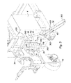
- the connecting means are configured to allow a substantially vertical movement of the rear gear 12 relative to the frame 4, between a first position, visible on the figure 4 and on the figure 5 (in solid lines), in which the rear gear 12 is positioned relative to the chassis 4 so that the ground clearance of the lifting gear 1 is minimal, and a second position, visible on the figure 5 (in dashed lines), wherein the rear gear 12 is positioned relative to the frame 4 so that the ground clearance of the lifting gear 4 is maximum.
- the plane formed by the bearing surfaces of the wheels 8, 16 on the ground may be substantially perpendicular to the axis of rotation of the boom 2 relative to the frame 4, and in the second position this axis of rotation of the boom 2 relative to the chassis 4 is inclined relative to the plane formed by the bearing surfaces of the wheels 8, 16 on the ground.
- the axis of rotation of the wheel 16 may be located above a plane containing the axes along which extend longitudinally the two beams 10 when the rear train 12 is in the first position, and be located below of this plane when the rear train 12 is in second position.
- substantially vertical displacement is meant a displacement of a first position at a second position with a non-zero vertical component, that is to say between two positions which are offset along a vertical axis Z of the machine 1 lifting.
- This displacement therefore includes a displacement in circular translation as described below.
- the connecting means advantageously comprise two rods 24 arranged relative to each other in deformable parallelogram.
- the movement of the rear gear 12 relative to the frame 4 is here a circular translational movement.
- Each connecting rod 24 here comprises a first end 240 pivotally mounted relative to the frame 4 about an axis substantially parallel to a transverse axis Y of the lifting gear 1, and a second end 242 connected to the rear gear 12, in particular to the frame 14, by a pivot link P1, P2 with a transverse axis Y.
- the lifting gear 1 further comprises drive means designed to move the rear gear 12 between the first and second positions.
- the drive means and the connecting means may be adapted to move the rear train 12 from the first position to the second position so as to compensate a slope ⁇ which is for example of the order of 6 °.
- the drive means may advantageously comprise a hydraulic cylinder 26 and a pressure sensor 28 configured to detect a predetermined threshold pressure value in a chamber of the cylinder 26.
- the hoist 1 may further comprise control means, such as a booster, designed to control the automatic stop of a displacement of the boom 2 when the pressure sensor 28 detects the predetermined threshold pressure value.
- control means can also be designed to control a movement of the boom 2 which is the opposite of that which caused the pressure variation in the inner chamber of the cylinder 26, so that the arrow 2 returns to a more stable position.
- the jack 26 can be arranged so that in the first position, its rod 30 is deployed, and that in the second position, its rod 30 is retracted.
- the drive means comprise a single jack 26.
- the costs are thus reduced compared to a solution in which two jacks would be used.
- the connecting means may comprise, in addition to the pair of connecting rods 24, a second pair of rods 32.
- These two pairs of rods 24, 32 are substantially symmetrical with respect to a median longitudinal plane of the lifting gear 1, that is to say a plane substantially perpendicular to a transverse direction Y of the hoist and separating the hoist 1 in two substantially similar parts.
- each pair of connecting rods 24, 32 forms a deformable parallelogram connecting the rear gear 12 to the chassis 4.
- each connecting rod 24, 32 may extend obliquely with respect to a transverse plane YZ of the hoist, so that the substantially symmetrical connecting rods of each pair form a V.
- the hydraulic jack 26 may comprise an end 260 connected to the rear gear 12, in particular to the frame 14, by a pivot link P3 having a transverse axis Y, and an end 262 mounted to rotate with respect to the frame 4 about a transverse axis. .
- the hydraulic cylinder 26 preferably extends between the two pairs of rods 24, 32.
- the rear gear 12, in particular the frame 14 may comprise an offset arm 34 extending towards the chassis 4, preferably in a direction substantially parallel to the longitudinal direction X of the lifting gear 1, and the jack 26 is connected by the pivot connection P3 to a distal end 340 of the offset arm 34, that is to say the end of the offset arm 34 which is closest to the frame 4.
- the lifting gear 1 may also comprise two stabilizing lateral feet 36, movable relative to the chassis 4 between an extended position, visible on the Figures 1 to 4 , in which a distal end 360 of the stabilizing lateral feet 36 is intended to bear against the ground and a folded position, visible on the figure 5 , in which this distal end 360 is intended to be arranged at a distance from the ground.
- the lifting gear 1 also comprises an attachment interface 38 fixed to the frame 4.
- the connecting means and the stabilizing lateral feet 36 are connected to the frame 4 via the interface 38 for fixing.
- connecting rods 24, 32 are connected to the attachment interface 38 by pivot links P4, P5 having a transverse axis Y.
- the hydraulic cylinder 26 can be connected to the chassis 4 via the interface 38 for fixing; the jack 26 is for example connected to the interface 38 for fixing by a pivot connection P6 transverse axis Y.
- the stabilizing lateral feet 36 may comprise a proximal end 362 connected to the attachment interface 38 by a pivot connection P7, P8 with a longitudinal axis X and a slot 40 formed between the proximal end 362 and the distal end 360.
- the lifting gear 1 further comprises two jacks 42 each having a proximal end 420 connected to the interface 38 for fixing by a pivot connection P9, P10 of longitudinal axis X and a distal end 422 slidably mounted in the slot 40 of the corresponding lateral foot 36.
- the lumen 40 may be arranged closer to the proximal end 362 than the distal end 360 of the corresponding stabilizing lateral foot 36.
Landscapes
- Engineering & Computer Science (AREA)
- Mechanical Engineering (AREA)
- Jib Cranes (AREA)
- Vehicle Cleaning, Maintenance, Repair, Refitting, And Outriggers (AREA)
Applications Claiming Priority (1)
| Application Number | Priority Date | Filing Date | Title |
|---|---|---|---|
| FR1451408A FR3017862B1 (fr) | 2014-02-21 | 2014-02-21 | Engin de levage avec reglage de garde au sol |
Publications (1)
| Publication Number | Publication Date |
|---|---|
| EP2910513A1 true EP2910513A1 (de) | 2015-08-26 |
Family
ID=51417329
Family Applications (1)
| Application Number | Title | Priority Date | Filing Date |
|---|---|---|---|
| EP15155725.3A Withdrawn EP2910513A1 (de) | 2014-02-21 | 2015-02-19 | Hebevorrichtung mit einer Regulierung der Höhenlage |
Country Status (2)
| Country | Link |
|---|---|
| EP (1) | EP2910513A1 (de) |
| FR (1) | FR3017862B1 (de) |
Cited By (2)
| Publication number | Priority date | Publication date | Assignee | Title |
|---|---|---|---|---|
| ITUA20163367A1 (it) * | 2016-05-12 | 2017-11-12 | Jacques Tranchero | Gru per il sollevamento ed il trasporto di carichi dotata di un sistema di trazione. |
| FR3077064A1 (fr) * | 2018-01-23 | 2019-07-26 | Mobilev Cranes | Engin de levage a fleche articulee |
Citations (6)
| Publication number | Priority date | Publication date | Assignee | Title |
|---|---|---|---|---|
| US2849124A (en) * | 1956-05-07 | 1958-08-26 | William H Warner | Engine auxiliary equipment handling jack assembly |
| WO1989000928A1 (en) * | 1987-07-24 | 1989-02-09 | Karlin, Gunvor (Legal Representative For The Estat | Cross-country vehicle |
| EP0383254A2 (de) * | 1989-02-17 | 1990-08-22 | Wagner Fördertechnik GmbH & Co KG | Hubwagen mit einer in vertikaler Richtung federbelasteten vorgespannten Antriebseinheit |
| WO2003013999A2 (en) * | 2001-08-03 | 2003-02-20 | The Government Of The United States Of America, As Represented By The Secretary Of The Department Of Health And Human Services, Centers For Disease Control And Prevention | Mobile load handling apparatus |
| WO2005108685A1 (en) * | 2004-04-30 | 2005-11-17 | The Board Of Regents For Oklahoma State University | Remotely operated self-loading/unloading railroad gondola car-top material handler |
| US20060049003A1 (en) * | 2004-09-03 | 2006-03-09 | Sica Patsy L | Material Handling Lift Vehicle And Suspension System For Use Therewith |
-
2014
- 2014-02-21 FR FR1451408A patent/FR3017862B1/fr active Active
-
2015
- 2015-02-19 EP EP15155725.3A patent/EP2910513A1/de not_active Withdrawn
Patent Citations (6)
| Publication number | Priority date | Publication date | Assignee | Title |
|---|---|---|---|---|
| US2849124A (en) * | 1956-05-07 | 1958-08-26 | William H Warner | Engine auxiliary equipment handling jack assembly |
| WO1989000928A1 (en) * | 1987-07-24 | 1989-02-09 | Karlin, Gunvor (Legal Representative For The Estat | Cross-country vehicle |
| EP0383254A2 (de) * | 1989-02-17 | 1990-08-22 | Wagner Fördertechnik GmbH & Co KG | Hubwagen mit einer in vertikaler Richtung federbelasteten vorgespannten Antriebseinheit |
| WO2003013999A2 (en) * | 2001-08-03 | 2003-02-20 | The Government Of The United States Of America, As Represented By The Secretary Of The Department Of Health And Human Services, Centers For Disease Control And Prevention | Mobile load handling apparatus |
| WO2005108685A1 (en) * | 2004-04-30 | 2005-11-17 | The Board Of Regents For Oklahoma State University | Remotely operated self-loading/unloading railroad gondola car-top material handler |
| US20060049003A1 (en) * | 2004-09-03 | 2006-03-09 | Sica Patsy L | Material Handling Lift Vehicle And Suspension System For Use Therewith |
Cited By (4)
| Publication number | Priority date | Publication date | Assignee | Title |
|---|---|---|---|---|
| ITUA20163367A1 (it) * | 2016-05-12 | 2017-11-12 | Jacques Tranchero | Gru per il sollevamento ed il trasporto di carichi dotata di un sistema di trazione. |
| WO2017195140A1 (en) * | 2016-05-12 | 2017-11-16 | Jacques Tranchero | Crane for lifting and transporting loads, equipped with a drive system |
| US11420852B2 (en) | 2016-05-12 | 2022-08-23 | Jacques Tranchero | Crane for lifting and transporting loads, equipped with a drive system |
| FR3077064A1 (fr) * | 2018-01-23 | 2019-07-26 | Mobilev Cranes | Engin de levage a fleche articulee |
Also Published As
| Publication number | Publication date |
|---|---|
| FR3017862A1 (fr) | 2015-08-28 |
| FR3017862B1 (fr) | 2019-03-29 |
Similar Documents
| Publication | Publication Date | Title |
|---|---|---|
| EP2374635B1 (de) | Achssystem, Achsmodul, das mindestens ein solches Achssytem umfasst und Fahrzeug, das mindestens ein solches Modul umfasst | |
| EP2858853A1 (de) | Kippbarer anhänger mit einer verschiebbaren und knickbaren deichsel | |
| EP1118531A1 (de) | Fahrzeug für unebenes Gelände | |
| BE1014630A3 (fr) | Engin de manutention de type diable. | |
| EP0100926B1 (de) | Fahrzeug zur Handhabung von Materialien mit orientierbarem Ausleger und eingebautem Stabilisiergestell | |
| EP2910513A1 (de) | Hebevorrichtung mit einer Regulierung der Höhenlage | |
| EP3949925B1 (de) | Abnehmbares elektrisches antriebssystem für ein rollendes objekt, gleichzeitiges und kombiniertes greifen und entfernen der räder in längsrichtung | |
| FR2641743A1 (fr) | Vehicule amenage pour etre equipe d'un outil interchangeable et outil destine a equiper un tel vehicule | |
| FR2929260A1 (fr) | Chariot de manutention, en particulier chariot elevateur | |
| EP2959759B1 (de) | Landwirtschaftliche maschine, die mit einer zentriervorrichtung ausgestattet ist | |
| EP4157188A1 (de) | Abnehmbares elektronisches antriebssystem für ein rollendes objekt mit automatischer richtungsblockierung | |
| EP2485977B1 (de) | Hebegerät für einen mäher mit extern montiertem heber | |
| FR2641234A1 (fr) | Dispositif pour relier une remorque a un tracteur | |
| FR2994169A1 (fr) | Engin de levage | |
| FR2574389A1 (fr) | Dispositif de securite pour vehicules de manutention a chargeur frontal | |
| EP1445179B1 (de) | Transportanhänger für Landwirtschaftgeräte | |
| EP0012095B1 (de) | Selbststabilisierendes Fahrzeug zum Heben und zur Handhabung von Lasten | |
| EP2692680B1 (de) | Hubgerät | |
| FR2872029A1 (fr) | Vehicule automobile pour personne a mobilite reduite | |
| EP1024108B1 (de) | Vorrichtung zur Umstellungskontrolle einer Tragstruktur eines Wagens | |
| FR2509711A1 (fr) | Dispositif elevateur a cabine ou plate-forme de travail | |
| FR2863246A1 (fr) | Remorque pour le transport d'engins tels que des machines agricoles. | |
| FR3110888A1 (fr) | Système de propulsion électrique amovible pour un objet roulant avec un moyen de préhension et de levage combinés et simultanés | |
| WO2001094152A1 (fr) | Dispositif basculeur pour vehicule utilitaire | |
| FR3077064A1 (fr) | Engin de levage a fleche articulee |
Legal Events
| Date | Code | Title | Description |
|---|---|---|---|
| PUAI | Public reference made under article 153(3) epc to a published international application that has entered the european phase |
Free format text: ORIGINAL CODE: 0009012 |
|
| AK | Designated contracting states |
Kind code of ref document: A1 Designated state(s): AL AT BE BG CH CY CZ DE DK EE ES FI FR GB GR HR HU IE IS IT LI LT LU LV MC MK MT NL NO PL PT RO RS SE SI SK SM TR |
|
| AX | Request for extension of the european patent |
Extension state: BA ME |
|
| STAA | Information on the status of an ep patent application or granted ep patent |
Free format text: STATUS: THE APPLICATION IS DEEMED TO BE WITHDRAWN |
|
| 18D | Application deemed to be withdrawn |
Effective date: 20160227 |