EP2910687A1 - Dispositif et procédé de fabrication d'un tunnel présentant plusieurs tronçons de tunnel - Google Patents
Dispositif et procédé de fabrication d'un tunnel présentant plusieurs tronçons de tunnel Download PDFInfo
- Publication number
- EP2910687A1 EP2910687A1 EP15156530.6A EP15156530A EP2910687A1 EP 2910687 A1 EP2910687 A1 EP 2910687A1 EP 15156530 A EP15156530 A EP 15156530A EP 2910687 A1 EP2910687 A1 EP 2910687A1
- Authority
- EP
- European Patent Office
- Prior art keywords
- formwork
- concreting
- station
- tunnel
- support
- Prior art date
- Legal status (The legal status is an assumption and is not a legal conclusion. Google has not performed a legal analysis and makes no representation as to the accuracy of the status listed.)
- Granted
Links
Images


Classifications
-
- E—FIXED CONSTRUCTIONS
- E02—HYDRAULIC ENGINEERING; FOUNDATIONS; SOIL SHIFTING
- E02D—FOUNDATIONS; EXCAVATIONS; EMBANKMENTS; UNDERGROUND OR UNDERWATER STRUCTURES
- E02D29/00—Independent underground or underwater structures; Retaining walls
- E02D29/063—Tunnels submerged into, or built in, open water
- E02D29/07—Tunnels or shuttering therefor preconstructed as a whole or continuously made, and moved into place on the water-bed, e.g. into a preformed trench
Definitions
- the invention relates to a device for producing a tunnel having several tunnel sections, in particular immersed tunnel, with a concreting station for cyclic concreting of tunnel sections, wherein the concreting station has a formwork arrangement with a bottom formwork, wherein a pushing device for moving the tunnel sections in the longitudinal direction of the concreting in a parking station is provided, wherein a support means, preferably a lattice girder, is provided for supporting an inner formwork of the formwork arrangement.
- the invention relates to a method for producing a tunnel sections having several tunnel sections, in particular immersed tunnel, wherein in a concreting a formwork arrangement is provided with a bottom formwork with which cyclically the tunnel sections are concreted, which pushed in the concreted state in the longitudinal direction of the concreting in a parking station be, with a support means, preferably a lattice girder, is provided for supporting an inner formwork of the formwork arrangement.
- a method for producing an underwater tunnel for example, from DE 26 19 510 known.
- individual tunnel sections are produced in a Taktschiebekeller.
- a carrying device which in the prior art has a lattice girder and a cage for bearing and guiding the lattice girder. So far, the lattice girder with the cage and the inner formwork were pushed out of the concreting station together with the finished tunnel section. After moving the tunnel section into the parking station, the lattice girder and the formwork were returned to the concreting station before a cleaning of the formwork was carried out. Disadvantageously, therefore, could be started with the cleaning of the formwork only after the advance of the tunnel section was completed and the formwork was pushed back into the concreting. This process was therefore disadvantageously time consuming.
- the object of the present invention is to eliminate or alleviate the disadvantages of the prior art.
- the invention is therefore particularly aimed at simplifying and accelerating the sequence in the production of the tunnel segments.
- the carrying device and the inner formwork are arranged substantially stationary.
- the tunnel section is displaceably mounted relative to the stationary support device or to the stationary formwork arrangement. Since the carrying device together with inner formwork remains during Verschubvorgang in the concreting and therefore unlike the prior art does not need to be moved, on the one hand to dispense with the arrangement of a cage and on the other hand on the Verschub vibration for the support means, resulting in significant material or cost savings can be achieved.
- the cleaning of the inner formwork can be started even while the tunnel section is being pushed out of the concreting station.
- the carrying device is preferably as a lattice girder performed; However, it can alternatively be provided a solid wall support.
- the formwork arrangement can, as usual, have an end formwork that can be transferred between a closed concreting position and an open position.
- the support means for the inner formwork on the side of the front formwork between a supported at a bottom of the concreting support position and a From the ground off position has convertible support member.
- an insertion opening for introducing a reinforcement in the formwork arrangement is formed.
- the front formwork is opened.
- the support element is lifted off the ground.
- an insertion opening is formed on the front side of the formwork arrangement, through which the reinforcement can be pushed between the formwork elements of the formwork arrangement.
- the formwork arrangement including the inner formwork and the support means are arranged in the longitudinal direction stationary in the concreting station during this process.
- an inner formwork is arranged in a Ausschalwolf at the time of reinforcement insert, wherein the lattice girder and a slab formwork lowered and a wall formwork and bottom flaps are retracted.
- the front formwork is brought into the closed concreting position and, on the other hand, the supporting element is supported on the floor.
- a height-adjustable upright element is preferably provided.
- the carrying device usually has a longitudinal section running in the concreting station and a longitudinal section running in the parking station.
- the running in the concreting station Longitudinal portion in which the insertion opening for the reinforcement forming position of the support means and the front formwork is cantilevered, wherein extending in the parking station longitudinal portion of the support means is supported by at least two support members on the previously concreted tunnel section.
- a support element is preferably provided for support on a ceiling area of the previously concreted tunnel section and a support element for support on a floor area of the previously concreted tunnel section.
- the front formwork is brought into the open position and on the other hand the support element of the support device in the region of the front formwork raised from the ground.
- the support means for the inner formwork along the concreting station in a cantilevered position, i. without support to the environment, arranged.
- a self-supporting lattice girder is preferably provided.
- the section of the carrying device running in the parking station has at least two supporting elements with which the carrying device can be supported on the previously concreted tunnel section.
- the carrying device is in the cantilevered position for introducing the reinforcement on the one hand at an end facing away from the concreting end of the support device with an upper side support on the ceiling area of the previously concreted, arranged in the park station tunnel section and on the other hand with a lower-side support element on the bottom area supported the previously concreted tunnel section.
- the lower-side support element is preferably arranged in this position adjacent to the concreting station between the support device and the previously concreted tunnel section.
- At least one support element is a support element displaceable in the longitudinal direction relative to the support device, in particular a roller block.
- a supporting element in the longitudinal direction immovably connected to the support means in the height-adjustable upright element and / or a linear drive element which can be supported on the ceiling area of the previously concreted tunnel section can be provided.
- roller block as a supporting element has the advantage that the roller block can be displaced in the longitudinal direction in order to fulfill different functions during the production process.
- the roller block is locatable in a first position between the tunnel section in the concreting station in the concreted state and the supporting device in order to assist in moving this tunnel section from the concreting station to the parking station.
- the roller block is arranged in the first position adjacent to the front formwork.
- the roller block is arranged in a second position, preferably substantially in a central longitudinal section of the carrying device, in order to bring about a support of the carrying device when inserting the reinforcement in the raised state of the support element.
- a further displaceable support element in particular a further roller block, be provided, with which the support device is supported when moving the tunnel section in the concreted state.
- a linear drive element in particular a hydraulic cylinder-piston drive or a mechanical spindle element, is preferably used.
- the carrying device has a post element which is displaceable between a raised and a lowered position and which is provided on the carrying device in the longitudinal direction so as to be immovable.
- the upright element is preferably arranged in a central region of the carrying device, with respect to its longitudinal direction, between the one end of the carrying device on the side of the concreting station and the other end of the carrying device on the side of the parking station.
- the carrying device in particular at the end remote from the concreting station, has a linear drive element, in particular a hydraulic cylinder-piston drive or a mechanical spindle element.
- roller block which is set in the concreted state of the tunnel section, before the Verschubvorgang in a position adjacent the upright element, so that the roller block after moving the tunnel section in a position at the end remote from the concreting end of Carrying device is arranged.
- the pusher has a plurality of transversely spaced apart and slidably mounted in the longitudinal direction sliding elements for Auflagerung the tunnel section in the concreting, wherein the bottom formwork has at least one height adjustable between a raised concreting and a lowered Ausschalwolf bottom formwork element, so that the tunnel section in the concreted State in the lowered Ausschalwolf the bottom formwork elements is displaceable together with the sliding elements from the concreting in the parking station.
- substantially the entire weight of the hardened tunnel section in the concreting station is carried by the sliding elements.
- the sliding elements are guided via sliding or rolling bearings on corresponding Verschubbahen slidably. It is essential here that the sliding elements are mounted directly, ie without linear drives such as lifting presses, on the Verschubbahen. Accordingly, the tunnel section during the Verschubvorgang between the concreting station and the parking station is mounted substantially auchnunver section on the sliding elements, which are preferably carried out substantially rigid.
- the bottom formwork elements are moved vertically downwards until the bottom formwork elements are present in the lowered Ausschal ein.
- the finished tunnel section with the aid of a suitable linear drive together with the underlying sliding elements in the horizontal plane, pushed in the longitudinal direction of the concreting become.
- a repositioning of the finished tunnel section is no longer necessary, since the tunnel section is supported both in the concreting position of the bottom formwork and in the Ausschal ein the bottom formwork by the sliding elements.
- the necessary in the prior art linear actuators such as lifting presses for repositioning the finished tunnel section can be omitted.
- the linear drive for moving the tunnel section in a horizontal plane by means of the sliding elements can be carried out particularly easily.
- a folding down of the bottom formwork elements in the area of the displacement paths for access to the lifting presses is no longer necessary. Accordingly, the bottom formwork elements are displaceable in the height direction between the raised concreting position and raised Ausschal ein.
- a plurality of sliding elements following each other in the longitudinal direction of the concreting or parking station are preferably provided, so that the tunnel section just concreted is displaceable together with at least one previously concreted tunnel section.
- the bearing surfaces between the sliding elements and the Verschubbahnen are designed as sliding bearings, wherein alternatively roller bearings can be provided.
- the finished concreted tunnel section can be pushed out of the concreting station on the sliding elements.
- the sliding elements are arranged substantially auchnunver section when moving the tunnel section between the concreting and the parking station.
- the usual in the prior art lifting presses in the form of hydraulic cylinders can be omitted for relocating the tunnel sections. After moving the tunnel section other sliding elements can be arranged in the concreting station, whereby it is of course also possible to recover previously used sliding elements.
- adjusting elements are provided for height adjustment of the bearing surfaces of the sliding elements. Accordingly, the bearing surfaces can be adjusted in height to ensure a substantially flat course of the sliding bearing between the sliding elements and the Verschubbahen.
- the sliding elements are displaceable substantially in the same height position on the Verschubbahen. Accordingly, in particular no lifting presses for relocating the tunnel section before moving from the concreting station are required. Relocating the tunnel elements on lowering wedges after reaching the final position for the expansion of lifting presses is also advantageously not necessary.
- the pushing device has a linear drive for displacing the tunnel section present in the concreted state from the concreting station to the parking station, wherein the linear drive has a longitudinally displaceable force introduction element, which between one in one Recess of the sliding element engaging operative position and a arranged outside the recess of the sliding element retraction position is pivotable.
- the force introduction element can be arranged in the operative position within the recess of the sliding element, so that the sliding element is advanced by actuation of the linear drive in the longitudinal direction.
- the linear drive preferably has a hydraulic cylinder-piston drive, which is connected at one end to the force introduction element and at the other end to a stationary bearing point. To retract the linear drive, the force introduction element from the operative position, in which the force introduction element is preferably arranged substantially stationary, in the retraction position, in which the force introduction element is preferably arranged substantially lying, pivots.
- the sliding elements on the underside has a plurality of longitudinally spaced recesses for the force introduction element of the linear drive. Accordingly, the sliding element can be displaced by the fact that the force introduction element of the linear drive is arranged in the operative position in a first step, is extended in a second step substantially by the distance between the adjacent recesses of the sliding element, is pivoted in a third step in the retraction position is retracted so far in a fourth step that the force introduction element is arranged below the longitudinal direction of the recess of the sliding element and is pivoted in a fifth step back into the operative position. This sequence is repeated until the tunnel section from the concreting station has been completely moved into the parking station.
- the tunnel section in the concreting station is superimposed in a simple manner on a plurality of transversely spaced sliding elements, wherein the bottom form in the concreted state of the tunnel section from a raised concreting position is transferred in a lowered Ausschalwolf, the tunnel section is moved in the concreted state in the lowered Ausschalwolf the bottom formwork together with the sliding elements of the concreting in the parking station.
- the tunnel section in the concreted state Due to the displacement of the tunnel section on the sliding elements, it is advantageously made possible for the tunnel section in the concreted state to be displaced substantially vertically on the sliding elements from the concreting station to the parking station.
- "height-invariant" means that the tunnel section does not have to be relocated to lifting presses prior to initiation of the transfer operation and is shifted into the parking station essentially at the same height position as in the concreting station.
- the usual hydraulic cylinder in the prior art be saved for relocating the concreted tunnel section.
- the sliding elements can be mounted adjustable in height to compensate for changes in the ground. After setting the height position of the bearing surfaces, however, the tunnel sections can be moved without lifting by means of lifting presses from the concreting in the parking station.
- the stationary arrangement of the carrying device is preferably provided in connection with the previously described embodiment of the sliding device with sliding elements, but can also be used with different pushing devices, without sliding elements.
- a known in the prior art method can be used, in which the finished concrete tunnel segment is moved to hydraulic lifting presses.
- the tunnel section to be concreted initially rests on the bottom formwork until the tunnel section has hardened sufficiently to be able to shell out the tunnel section.
- the tunnel section is relocated to lifting presses, so then the bottom formwork can be lowered.
- the floor formwork can be folded down in the area of the displacement paths.
- the finished concrete tunnel segment is moved together with all lifting presses in the final position.
- the tunnel segments can be relocated after reaching the end position on lowering wedges to remove the hydraulic cylinder before flooding the tunnel sections can.
- the formwork arrangement has an end formwork element which can be pivoted between a substantially vertically arranged position and a substantially horizontally arranged open position.
- the front formwork element can be swung up, wherein the insertion opening is released for the reinforcement.
- the front formwork segment is pivoted downwards.
- the end formwork element is substantially U-shaped. In a tunnel with several tubes, several pivotable front formwork elements can be provided.
- the concreting station has an end formwork portal with a portal element arranged transversely above a slab formwork, on which element the formwork element is pivotably arranged.
- the front formwork element can be mounted displaceably in the vertical direction.
- the front formwork can be constructed from a plurality of formwork elements, which were individually mounted on the formwork arrangement.
- a carrying device preferably a lattice girder, is provided for supporting an inner formwork of the formwork arrangement, wherein the carrying device and the inner formwork are arranged substantially stationary when moving the tunnel section from the concreting station into the parking station. Accordingly, the inner formwork, in particular the other formwork elements of the formwork arrangement, remains in the concreting station, while the tunnel section is driven in the concreted state into the parking station. As a result, a cleaning of the inner formwork can advantageously be carried out earlier.
- an end shuttering of the formwork arrangement is concluded for concreting the tunnel section, wherein the support means for the inner formwork on the side of the front formwork by means of a support member on a floor the concreting station is supported, wherein the support element after moving the tunnel section in the concreted state in the parking station and the opening of the front formwork in a raised position is brought from the bottom of the concreting station, whereupon a reinforcement is introduced through a released on the front side of the concreting insertion opening in the formwork arrangement.
- a longitudinally displaceable support element in particular a roller block, is preferably arranged between the support device and the finished tunnel section.
- the support element is preferably placed on an end region of the support device facing the front formwork.
- a Auflagerung for the support device when moving the tunnel section is provided in the finished concrete state of the concreting in the parking station.
- the carrying device can also be supported with another displaceable support element, in particular a further roller block, on the previously concreted tunnel section in the parking station before the displacement of the tunnel section just concreted into the parking station is initiated.
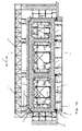
- Fig. 1a shows in cross-section a device 1 for producing a tunnel 2, in particular immersion tunnel, which has a plurality of longitudinally 15 consecutive tunnel sections 3 (see. Fig. 2 to 8 ) having.
- a plurality of tunnel sections 3 can be joined together to form a tunnel element, wherein the tunnel 2 can be constructed from a plurality of such tunnel elements.
- the device 1 has a concreting station 4 for cyclically concreting the tunnel sections 3.
- Fig. 1 2 schematically show a bottom plate 4 'and side walls 4 "of the concreting station 4.
- the concreting station 4 has a formwork arrangement 5, which in particular comprises a bottom formwork 6 with several bottom formwork elements 7, an interior formwork 8 with a wall formwork 9 and a ceiling formwork 10 External formwork 12 and an end formwork 13 (see also Fig. 1b ) having.
- the inner formwork 8 is arranged on a support device 14 in the form of a lattice girder.
- a pusher 17 is provided to move the tunnel sections 3 in the longitudinal direction 15 from the concreting station 4 in a parking station 16 (see. Fig. 2 to 8 ) to move the tunnel sections 3 in the longitudinal direction 15 from the concreting station 4 in a parking station 16 (see. Fig. 2 to 8 ) to move the tunnel sections 3 in the longitudinal direction 15 from the concreting station 4 in a parking station 16 (see. Fig. 2 to 8 ) a pusher 17 is provided.
- the thrust device 17 more in the transverse direction 18 (ie in the direction perpendicular to the longitudinal direction 15) spaced from each other and slidably mounted in the longitudinal direction 15 sliding elements 19 for bearing the tunnel section 3 in the concreting 4.
- the bottom formwork elements 7 of the bottom formwork 6 are displaceable between a raised concreting position and a lowered Ausschalwolf.
- the bottom formwork elements 7 are mounted on hydraulic cylinder-piston drives 7 ', which are supported on foundations 7 "of the concreting station 4 Fig. 1 the middle and right bottom formwork elements 7 are schematically in the raised concreting position and the left one Floor formwork element 7 located in the lowered Ausschalwolf.
- the tunnel section 3 can be displaced out of the concreting station 4 into the parking station 16 together with the sliding elements 19 in the concreted-out state in the lowered disengaging position of the floor formwork elements 7.
- Fig. 1a (see also Fig. 2 to 8 . 13 ) faceds seen, are provided as sliding elements 19 in the longitudinal direction 15 of the concreting 4 extended support members having on the top bearing surfaces 20 for supporting the tunnel section 3 and on the bottom bearing surfaces 21 for displacement on Verschubbahen 22 extending in the longitudinal direction 15 between the concreting 4 and the parking station 16 extend. From the drawing is schematically seen that between the sliding elements 19 and the Verschubbahnen 22 or foundations adjustment 23 (see. Fig. 13 ) are provided for height adjustment of the bearing surfaces 21.
- Fig. 1a how out Fig. 1a Furthermore, it can be seen, the support means 14 and at least the inner formwork 8 of the formwork arrangement 5 are arranged stationary.
- a support member 24 for supporting the support means 14 can be seen between the support means 14 and the tunnel section 3.
- Fig. 1 is provided as a support member 24, a roller block with a lower side footprint and a top-side roller member on which the support means 14 during displacement of the tunnel section 3 in the concreted state from the concreting station 4 runs (see. Fig. 2 to 8 ).
- the formwork arrangement 5 for the front formwork 13 has an end formwork element 25 which is disposed between a substantially vertically arranged position (cf. Fig. 1b . 2 ) and one in Fig. 1a shown, substantially horizontally disposed open position is pivotable.
- the concreting station 4 has an end formwork portal 26 with a portal element 27, which extends in the transverse direction 18 above the slab formwork 10, on which the end formwork element 25 is secured by means of a tension element 28 (cf. Fig. 2 ) is arranged pivotably.
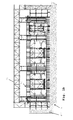
- Fig. 2 to 8 the individual steps of the manufacturing method according to the invention are shown, which can be performed with the manufacturing apparatus 1.
- a tunnel section 3 is currently being produced in the concreting station 4, wherein schematically the inflowing concrete 29 is drawn.
- the formwork arrangement 5 is in this case in the closed position, wherein in particular the front formwork element 25 is arranged in the downwardly pivoted, substantially vertical position.
- the tunnel section 3 is supported on the sliding elements 19, which are mounted displaceably on the Verschubbahnen 22.
- Fig. 1 schematically drawn worker.
- Fig. 3 the concreting process is completed.
- the front formwork element 25 is pivoted by means of the tension element 28 upwards into the open, substantially horizontally arranged position.
- the first roller block 24 ' is offset from the position indicated by solid lines in the parking station 16 in the position indicated by dashed lines on the end formwork end of the concreting station 4.
- the second roller block 24 is offset from the position indicated by solid lines at one end of the parking station 16 in the position indicated by dashed lines on the other, the concreting station 4 facing end.
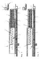
- Fig. 4 the tunnel section 3 is moved in the concreted state on the sliding elements 19 of the concreting station 4 in the parking station 16.
- the support device 14 and the formwork assembly 5 including the inner formwork 8 are arranged stationary.
- the roller blocks 24 ', 24''along the support means 14 are moved.
- the tunnel section 3 was moved to the parking station 16.
- the carrying device 14 is brought into a freely projecting into the concreting station 4 position.
- the support means 14 on the one hand on the first roller block 24 ' is supported, which in accordance with Fig. 5 approximately in the middle of the support means 14, with respect to the longitudinal direction 15, is located.
- the carrying device 14 at the end region arranged in the parking station has a further supporting element 24 in the form of a linear drive element 30, with which the carrying device 14 can be supported on the ceiling area of the previously concreted tunnel section 3 '.
- the linear drive element preferably a hydraulic cylinder-piston drive
- the linear drive element is extended in a vertical direction against the ceiling area of the tunnel section 3.
- the support device 14 on the side of the front formwork 13 a support member 32, which in concreting the tunnel section 3 (see. Fig. 1 ) and when moving the tunnel section 3 in the parking station 16 (see. Fig. 2, 3rd ) is arranged in a supported on a bottom 31 of the concreting 4 support position.
- the support member 32 is transferred to a raised position from the bottom 31, wherein the support means 14 is held solely by the first roller block 24 'and the extended drive member 30 in the parking station 16.
- Fig. 6 the reinforcement 34 is pushed by the insertion opening 33 provided on the end face in the formwork arrangement 5, wherein in the drawing also schematically a reinforcement frame 34 'for supporting the reinforcement 34 can be seen.
- Fig. 7 is the front formwork element 25 down in the vertical position folded.
- the inner formwork 8 and the outer formwork 12 are closed.
- Fig. 8 the front formwork 13 is moved in the longitudinal direction 15 in the closed concreting position to produce the next tunnel section 3. After that, the procedure of the Fig. 2 to 8 be repeated as often as you like. It should be noted that for the concreting of a very first tunnel section at the end of the device 1 opposite the insertion opening 33, an end formwork is likewise provided.
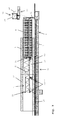
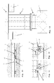
- Fig. 9 shows an alternative embodiment of the device 1, which is in the manner of supporting the support means 14 at the tunnel section 3 in the parking station 16 of that of Fig. 2 to 8 different.
- Fig. 9 When the method is carried out, only one single roller block 24 "'is shown, with solid lines indicating the current position of the roller block 24"' during displacement of the tunnel section 3 and with dashed lines the end positions of the roller block 24 "''' before the Verschubvorgang in a position adjacent to the upright element 35 set (see arrows 40), so that the roller block 24 '' after moving the tunnel section 3 in a position at the end remote from the concreting station 4 end of the support means 17 is arranged.
- the carrying device 14 is connected to a height-adjustable, in particular telescopic, upright element 35 with which the carrying device 14 can be supported on the bottom region of the tunnel section 3.
- a supporting element in the form of the linear drive element 30 is supported on the ceiling region of the tunneling element previously concreted tunnel section 3 'in the par kstation 16 provided.
- the upright element 35 is arranged in the longitudinal direction 15 of the carrying device 14 between the support element 30 and the support element 32.
- the pusher 17 has a linear drive 36 for moving the present in the concreted state tunnel section 3 of the concreting station 4 in the parking station 16.
- a linear drive 36 for moving the present in the concreted state tunnel section 3 of the concreting station 4 in the parking station 16.
- a hydraulic cylinder-piston drive provided, which has a longitudinally displaceable 15 force introduction element 37.
- the force introduction element 37 cooperates with recesses 38 of the sliding element 19, which are provided at regular intervals on the underside of the sliding element 19.
- the force introduction element 37 between a in one of the recesses 38 of the sliding member 19 engaging, upright operative position (see. Fig. 11 ) and an outside of the recesses 38 of the sliding member 19 arranged flat lying retraction position (see. Fig.
- the force introduction element 37 is arranged in one of the recesses 38 of the sliding element 19 in the operative position and then advanced in the longitudinal direction 14. Thereafter, the force introduction element 37 is pivoted into the lying retraction position and retracted counter to the feed direction 15, whereupon the force introduction element 37 is pivoted into the operative position at the next recess 38. Thereby, the sliding member 19 can be advanced stepwise together with the tunnel section 3.
Landscapes
- Engineering & Computer Science (AREA)
- Environmental & Geological Engineering (AREA)
- Life Sciences & Earth Sciences (AREA)
- General Life Sciences & Earth Sciences (AREA)
- Mining & Mineral Resources (AREA)
- Paleontology (AREA)
- Civil Engineering (AREA)
- General Engineering & Computer Science (AREA)
- Structural Engineering (AREA)
- Lining And Supports For Tunnels (AREA)
Priority Applications (1)
| Application Number | Priority Date | Filing Date | Title |
|---|---|---|---|
| EP15156530.6A EP2910687B1 (fr) | 2014-02-25 | 2015-02-25 | Dispositif et procédé de fabrication d'un tunnel présentant plusieurs tronçons de tunnel |
Applications Claiming Priority (2)
| Application Number | Priority Date | Filing Date | Title |
|---|---|---|---|
| EP14156569 | 2014-02-25 | ||
| EP15156530.6A EP2910687B1 (fr) | 2014-02-25 | 2015-02-25 | Dispositif et procédé de fabrication d'un tunnel présentant plusieurs tronçons de tunnel |
Publications (2)
| Publication Number | Publication Date |
|---|---|
| EP2910687A1 true EP2910687A1 (fr) | 2015-08-26 |
| EP2910687B1 EP2910687B1 (fr) | 2016-09-21 |
Family
ID=50190252
Family Applications (1)
| Application Number | Title | Priority Date | Filing Date |
|---|---|---|---|
| EP15156530.6A Active EP2910687B1 (fr) | 2014-02-25 | 2015-02-25 | Dispositif et procédé de fabrication d'un tunnel présentant plusieurs tronçons de tunnel |
Country Status (2)
| Country | Link |
|---|---|
| EP (1) | EP2910687B1 (fr) |
| DK (1) | DK2910687T3 (fr) |
Cited By (6)
| Publication number | Priority date | Publication date | Assignee | Title |
|---|---|---|---|---|
| CN105604092A (zh) * | 2016-03-04 | 2016-05-25 | 中铁隧道集团二处有限公司 | 一种用于沉管隧道中管节浮运的工装 |
| EP3450632A1 (fr) * | 2017-08-30 | 2019-03-06 | CCCC Highway Consultants Co., Ltd | Structure de section de tube précontraint et son procédé de construction |
| CN110524691A (zh) * | 2019-08-13 | 2019-12-03 | 中交第四航务工程局有限公司 | 沉管隧道外侧模板体系及施工方法 |
| CN112878362A (zh) * | 2021-01-07 | 2021-06-01 | 中国二十冶集团有限公司 | 综合管廊滑模装置及施工方法 |
| CN113352439A (zh) * | 2021-04-16 | 2021-09-07 | 中国交通建设股份有限公司 | 沉管管节上部预制装置、工厂法沉管预制系统及预制方法 |
| CN119195802A (zh) * | 2024-09-27 | 2024-12-27 | 中冶武勘工程技术有限公司 | 一种岩洞储气库钢内衬施工工艺 |
Citations (5)
| Publication number | Priority date | Publication date | Assignee | Title |
|---|---|---|---|---|
| DE1247369B (de) * | 1963-07-19 | 1967-08-17 | Holzmann Philipp Ag | Verfahren zum Herstellen eines Unterwassertunnels |
| DE2619510A1 (de) | 1976-05-03 | 1977-11-10 | Kunz Alfred & Co | Verfahren und vorrichtung zum herstellen eines unterwassertunnels aus stahlbeton |
| KR900007944Y1 (ko) | 1987-02-25 | 1990-09-03 | 남호정 | 원형 거푸집 |
| EP0500221A1 (fr) | 1991-01-28 | 1992-08-26 | NORWEGIAN CONTRACTORS a.s. | Procédé et dispositif pour la construction de structures en béton pratiquement horizontale de grande longueur et en forme de coquille |
| KR20140008067A (ko) | 2012-07-10 | 2014-01-21 | 한국철도기술연구원 | 가변형 시스템 거푸집을 이용한 저심도 터널 구조물 시공방법 |
-
2015
- 2015-02-25 DK DK15156530.6T patent/DK2910687T3/en active
- 2015-02-25 EP EP15156530.6A patent/EP2910687B1/fr active Active
Patent Citations (5)
| Publication number | Priority date | Publication date | Assignee | Title |
|---|---|---|---|---|
| DE1247369B (de) * | 1963-07-19 | 1967-08-17 | Holzmann Philipp Ag | Verfahren zum Herstellen eines Unterwassertunnels |
| DE2619510A1 (de) | 1976-05-03 | 1977-11-10 | Kunz Alfred & Co | Verfahren und vorrichtung zum herstellen eines unterwassertunnels aus stahlbeton |
| KR900007944Y1 (ko) | 1987-02-25 | 1990-09-03 | 남호정 | 원형 거푸집 |
| EP0500221A1 (fr) | 1991-01-28 | 1992-08-26 | NORWEGIAN CONTRACTORS a.s. | Procédé et dispositif pour la construction de structures en béton pratiquement horizontale de grande longueur et en forme de coquille |
| KR20140008067A (ko) | 2012-07-10 | 2014-01-21 | 한국철도기술연구원 | 가변형 시스템 거푸집을 이용한 저심도 터널 구조물 시공방법 |
Cited By (7)
| Publication number | Priority date | Publication date | Assignee | Title |
|---|---|---|---|---|
| CN105604092A (zh) * | 2016-03-04 | 2016-05-25 | 中铁隧道集团二处有限公司 | 一种用于沉管隧道中管节浮运的工装 |
| CN105604092B (zh) * | 2016-03-04 | 2017-06-16 | 中铁隧道集团二处有限公司 | 一种用于沉管隧道中管节浮运的工装 |
| EP3450632A1 (fr) * | 2017-08-30 | 2019-03-06 | CCCC Highway Consultants Co., Ltd | Structure de section de tube précontraint et son procédé de construction |
| CN110524691A (zh) * | 2019-08-13 | 2019-12-03 | 中交第四航务工程局有限公司 | 沉管隧道外侧模板体系及施工方法 |
| CN112878362A (zh) * | 2021-01-07 | 2021-06-01 | 中国二十冶集团有限公司 | 综合管廊滑模装置及施工方法 |
| CN113352439A (zh) * | 2021-04-16 | 2021-09-07 | 中国交通建设股份有限公司 | 沉管管节上部预制装置、工厂法沉管预制系统及预制方法 |
| CN119195802A (zh) * | 2024-09-27 | 2024-12-27 | 中冶武勘工程技术有限公司 | 一种岩洞储气库钢内衬施工工艺 |
Also Published As
| Publication number | Publication date |
|---|---|
| HK1214320A1 (zh) | 2016-07-22 |
| EP2910687B1 (fr) | 2016-09-21 |
| DK2910687T3 (en) | 2017-01-16 |
Similar Documents
| Publication | Publication Date | Title |
|---|---|---|
| EP2910687B1 (fr) | Dispositif et procédé de fabrication d'un tunnel présentant plusieurs tronçons de tunnel | |
| EP2083977B1 (fr) | Système de coffrage pour le bétonnage d'éléments préfabriqués, comprenant un coffrage extérieur et un coffrage central | |
| EP3572198B1 (fr) | Coffrage central pour un système de coffrage destiné à bétonner un corps de cloche | |
| DE102007026020A1 (de) | Selbstklettersystem und Verfahren zum Betonieren eines Unterzugs und/oder Montieren eines Fertigteils mittels eines Selbstklettersystems | |
| DE1810310A1 (de) | Verfahren und Einrichtung zur Herstellung eines Stahlbetontragwerkes | |
| DE2918652A1 (de) | Verfahren und schalung zum herstellen von monolithischen stahlbetonraumzellen, insbesondere von fertiggaragen | |
| DE2935726A1 (de) | Vorrichtung zum giessen von betonwaenden | |
| DE2122874A1 (de) | Verfahren und Vorrichtung zum Herstellen dreidimensionaler, aus Beton oder dgl. geformter Bauelemente | |
| DE102007019383A1 (de) | Batterieschalung zur vertikalen Fertigung von flächigen Betonfertigteilen | |
| DE2400790C2 (de) | Verfahren und Vorrichtung zur Herstellung von Raumzellen aus Stahlbeton, z.B. Fertiggaragen | |
| DE1683876C2 (de) | Vorrichtung zum Herstellen von zumindest einseitig offenen, raumgroßen Baukörpern aus Stahlbeton, insbesondere von Fertiggaragen | |
| DE102016120047B4 (de) | Vorrichtung und Verfahren zur einstückigen Herstellung eines drei Seitenelemente sowie ein Bodenelement und/oder ein Deckenelement aufweisenden Raummoduls | |
| DE2417805C2 (de) | Schalungskern zur Herstellung von einseitig offenen Raumzellen aus Stahlbeton | |
| DE2436088A1 (de) | Verfahrbare schalungsvorrichtung | |
| DE2531284A1 (de) | Schalung zur herstellung von insbesondere fuenfseitig geschlossenen, vorzugsweise quaderfoermigen und monolithischen raumzellen aus stahlbeton | |
| DE2745054C3 (de) | Kernschalung zum Herstellen von zumindest einseitig offenen Raumzellen aus Stahlbeton | |
| DE2046903A1 (de) | Verfahren zum Herstellen eines Glocken korpers fur größere Bauzellen und Vornch tung zum Ausfuhren des Verfahrens | |
| AT395742B (de) | Verfahren zur errichtung von baukoerpern aus giessfaehigen, aushaertbaren materialien und einrichtung zur durchfuehrung des verfahrens | |
| DE2252087C3 (de) | Schalung zur horizontalen Fertigung von Stahlbetonraumzellen, insbesondere von Fertiggaragen, welche einen Boden und eine offene Stirnseite aufweisen, und Verfahren zum Einbringen von Beton in die Schalung | |
| DE10016978B4 (de) | Vorrichtung zum Herstellen von Raumzellen aus Beton | |
| DE2513643A1 (de) | Anlage zum herstellen von raumzellen | |
| DE2416380A1 (de) | Schalung zum herstellen grossformatiger betonhohlkoerper, wie raumzellen, garagen o.dgl. | |
| DE2111650B2 (de) | Vorrichtung zur serienmäßigen Herstellung von einseitig offenen Raumzellen aus Beton, insbesondere von Fertiggaragen | |
| DE6944097U (de) | Schalung fuer grossformatige betonhohlkoerper, z.b. bauwerkszellen. | |
| DE3025172C2 (de) | Verfahren und Einrichtung zum Herstellen von plattenförmigen Betonbauelementen |
Legal Events
| Date | Code | Title | Description |
|---|---|---|---|
| PUAI | Public reference made under article 153(3) epc to a published international application that has entered the european phase |
Free format text: ORIGINAL CODE: 0009012 |
|
| AK | Designated contracting states |
Kind code of ref document: A1 Designated state(s): AL AT BE BG CH CY CZ DE DK EE ES FI FR GB GR HR HU IE IS IT LI LT LU LV MC MK MT NL NO PL PT RO RS SE SI SK SM TR |
|
| AX | Request for extension of the european patent |
Extension state: BA ME |
|
| 17P | Request for examination filed |
Effective date: 20160224 |
|
| RBV | Designated contracting states (corrected) |
Designated state(s): AL AT BE BG CH CY CZ DE DK EE ES FI FR GB GR HR HU IE IS IT LI LT LU LV MC MK MT NL NO PL PT RO RS SE SI SK SM TR |
|
| REG | Reference to a national code |
Ref country code: DE Ref legal event code: R079 Ref document number: 502015000169 Country of ref document: DE Free format text: PREVIOUS MAIN CLASS: E02D0029050000 Ipc: E02D0029070000 |
|
| GRAP | Despatch of communication of intention to grant a patent |
Free format text: ORIGINAL CODE: EPIDOSNIGR1 |
|
| RIC1 | Information provided on ipc code assigned before grant |
Ipc: E02D 29/07 20060101AFI20160414BHEP |
|
| INTG | Intention to grant announced |
Effective date: 20160503 |
|
| REG | Reference to a national code |
Ref country code: HK Ref legal event code: DE Ref document number: 1214320 Country of ref document: HK |
|
| GRAS | Grant fee paid |
Free format text: ORIGINAL CODE: EPIDOSNIGR3 |
|
| GRAA | (expected) grant |
Free format text: ORIGINAL CODE: 0009210 |
|
| AK | Designated contracting states |
Kind code of ref document: B1 Designated state(s): AL AT BE BG CH CY CZ DE DK EE ES FI FR GB GR HR HU IE IS IT LI LT LU LV MC MK MT NL NO PL PT RO RS SE SI SK SM TR |
|
| REG | Reference to a national code |
Ref country code: GB Ref legal event code: FG4D Free format text: NOT ENGLISH |
|
| REG | Reference to a national code |
Ref country code: CH Ref legal event code: EP |
|
| REG | Reference to a national code |
Ref country code: AT Ref legal event code: REF Ref document number: 831178 Country of ref document: AT Kind code of ref document: T Effective date: 20161015 |
|
| REG | Reference to a national code |
Ref country code: IE Ref legal event code: FG4D Free format text: LANGUAGE OF EP DOCUMENT: GERMAN |
|
| REG | Reference to a national code |
Ref country code: DE Ref legal event code: R096 Ref document number: 502015000169 Country of ref document: DE |
|
| REG | Reference to a national code |
Ref country code: SE Ref legal event code: TRGR |
|
| REG | Reference to a national code |
Ref country code: DK Ref legal event code: T3 Effective date: 20170110 |
|
| REG | Reference to a national code |
Ref country code: LT Ref legal event code: MG4D Ref country code: NL Ref legal event code: MP Effective date: 20160921 |
|
| PG25 | Lapsed in a contracting state [announced via postgrant information from national office to epo] |
Ref country code: FI Free format text: LAPSE BECAUSE OF FAILURE TO SUBMIT A TRANSLATION OF THE DESCRIPTION OR TO PAY THE FEE WITHIN THE PRESCRIBED TIME-LIMIT Effective date: 20160921 Ref country code: NO Free format text: LAPSE BECAUSE OF FAILURE TO SUBMIT A TRANSLATION OF THE DESCRIPTION OR TO PAY THE FEE WITHIN THE PRESCRIBED TIME-LIMIT Effective date: 20161221 Ref country code: LT Free format text: LAPSE BECAUSE OF FAILURE TO SUBMIT A TRANSLATION OF THE DESCRIPTION OR TO PAY THE FEE WITHIN THE PRESCRIBED TIME-LIMIT Effective date: 20160921 Ref country code: RS Free format text: LAPSE BECAUSE OF FAILURE TO SUBMIT A TRANSLATION OF THE DESCRIPTION OR TO PAY THE FEE WITHIN THE PRESCRIBED TIME-LIMIT Effective date: 20160921 |
|
| PG25 | Lapsed in a contracting state [announced via postgrant information from national office to epo] |
Ref country code: LV Free format text: LAPSE BECAUSE OF FAILURE TO SUBMIT A TRANSLATION OF THE DESCRIPTION OR TO PAY THE FEE WITHIN THE PRESCRIBED TIME-LIMIT Effective date: 20160921 Ref country code: GR Free format text: LAPSE BECAUSE OF FAILURE TO SUBMIT A TRANSLATION OF THE DESCRIPTION OR TO PAY THE FEE WITHIN THE PRESCRIBED TIME-LIMIT Effective date: 20161222 Ref country code: NL Free format text: LAPSE BECAUSE OF FAILURE TO SUBMIT A TRANSLATION OF THE DESCRIPTION OR TO PAY THE FEE WITHIN THE PRESCRIBED TIME-LIMIT Effective date: 20160921 |
|
| PG25 | Lapsed in a contracting state [announced via postgrant information from national office to epo] |
Ref country code: EE Free format text: LAPSE BECAUSE OF FAILURE TO SUBMIT A TRANSLATION OF THE DESCRIPTION OR TO PAY THE FEE WITHIN THE PRESCRIBED TIME-LIMIT Effective date: 20160921 Ref country code: RO Free format text: LAPSE BECAUSE OF FAILURE TO SUBMIT A TRANSLATION OF THE DESCRIPTION OR TO PAY THE FEE WITHIN THE PRESCRIBED TIME-LIMIT Effective date: 20160921 |
|
| PG25 | Lapsed in a contracting state [announced via postgrant information from national office to epo] |
Ref country code: BG Free format text: LAPSE BECAUSE OF FAILURE TO SUBMIT A TRANSLATION OF THE DESCRIPTION OR TO PAY THE FEE WITHIN THE PRESCRIBED TIME-LIMIT Effective date: 20161221 Ref country code: PL Free format text: LAPSE BECAUSE OF FAILURE TO SUBMIT A TRANSLATION OF THE DESCRIPTION OR TO PAY THE FEE WITHIN THE PRESCRIBED TIME-LIMIT Effective date: 20160921 Ref country code: CZ Free format text: LAPSE BECAUSE OF FAILURE TO SUBMIT A TRANSLATION OF THE DESCRIPTION OR TO PAY THE FEE WITHIN THE PRESCRIBED TIME-LIMIT Effective date: 20160921 Ref country code: IS Free format text: LAPSE BECAUSE OF FAILURE TO SUBMIT A TRANSLATION OF THE DESCRIPTION OR TO PAY THE FEE WITHIN THE PRESCRIBED TIME-LIMIT Effective date: 20170121 Ref country code: SM Free format text: LAPSE BECAUSE OF FAILURE TO SUBMIT A TRANSLATION OF THE DESCRIPTION OR TO PAY THE FEE WITHIN THE PRESCRIBED TIME-LIMIT Effective date: 20160921 Ref country code: ES Free format text: LAPSE BECAUSE OF FAILURE TO SUBMIT A TRANSLATION OF THE DESCRIPTION OR TO PAY THE FEE WITHIN THE PRESCRIBED TIME-LIMIT Effective date: 20160921 Ref country code: PT Free format text: LAPSE BECAUSE OF FAILURE TO SUBMIT A TRANSLATION OF THE DESCRIPTION OR TO PAY THE FEE WITHIN THE PRESCRIBED TIME-LIMIT Effective date: 20170123 Ref country code: BE Free format text: LAPSE BECAUSE OF NON-PAYMENT OF DUE FEES Effective date: 20170228 Ref country code: SK Free format text: LAPSE BECAUSE OF FAILURE TO SUBMIT A TRANSLATION OF THE DESCRIPTION OR TO PAY THE FEE WITHIN THE PRESCRIBED TIME-LIMIT Effective date: 20160921 |
|
| REG | Reference to a national code |
Ref country code: DE Ref legal event code: R097 Ref document number: 502015000169 Country of ref document: DE |
|
| PG25 | Lapsed in a contracting state [announced via postgrant information from national office to epo] |
Ref country code: IT Free format text: LAPSE BECAUSE OF FAILURE TO SUBMIT A TRANSLATION OF THE DESCRIPTION OR TO PAY THE FEE WITHIN THE PRESCRIBED TIME-LIMIT Effective date: 20160921 |
|
| PLBE | No opposition filed within time limit |
Free format text: ORIGINAL CODE: 0009261 |
|
| STAA | Information on the status of an ep patent application or granted ep patent |
Free format text: STATUS: NO OPPOSITION FILED WITHIN TIME LIMIT |
|
| 26N | No opposition filed |
Effective date: 20170622 |
|
| REG | Reference to a national code |
Ref country code: HK Ref legal event code: GR Ref document number: 1214320 Country of ref document: HK |
|
| PG25 | Lapsed in a contracting state [announced via postgrant information from national office to epo] |
Ref country code: MC Free format text: LAPSE BECAUSE OF FAILURE TO SUBMIT A TRANSLATION OF THE DESCRIPTION OR TO PAY THE FEE WITHIN THE PRESCRIBED TIME-LIMIT Effective date: 20160921 |
|
| REG | Reference to a national code |
Ref country code: IE Ref legal event code: MM4A |
|
| PG25 | Lapsed in a contracting state [announced via postgrant information from national office to epo] |
Ref country code: SI Free format text: LAPSE BECAUSE OF FAILURE TO SUBMIT A TRANSLATION OF THE DESCRIPTION OR TO PAY THE FEE WITHIN THE PRESCRIBED TIME-LIMIT Effective date: 20160921 |
|
| REG | Reference to a national code |
Ref country code: FR Ref legal event code: ST Effective date: 20171031 |
|
| PG25 | Lapsed in a contracting state [announced via postgrant information from national office to epo] |
Ref country code: LU Free format text: LAPSE BECAUSE OF NON-PAYMENT OF DUE FEES Effective date: 20170225 |
|
| PG25 | Lapsed in a contracting state [announced via postgrant information from national office to epo] |
Ref country code: FR Free format text: LAPSE BECAUSE OF NON-PAYMENT OF DUE FEES Effective date: 20170228 |
|
| REG | Reference to a national code |
Ref country code: BE Ref legal event code: MM Effective date: 20170228 |
|
| PG25 | Lapsed in a contracting state [announced via postgrant information from national office to epo] |
Ref country code: IE Free format text: LAPSE BECAUSE OF NON-PAYMENT OF DUE FEES Effective date: 20170225 |
|
| REG | Reference to a national code |
Ref country code: CH Ref legal event code: PL |
|
| PG25 | Lapsed in a contracting state [announced via postgrant information from national office to epo] |
Ref country code: MT Free format text: LAPSE BECAUSE OF FAILURE TO SUBMIT A TRANSLATION OF THE DESCRIPTION OR TO PAY THE FEE WITHIN THE PRESCRIBED TIME-LIMIT Effective date: 20160921 |
|
| PG25 | Lapsed in a contracting state [announced via postgrant information from national office to epo] |
Ref country code: AL Free format text: LAPSE BECAUSE OF FAILURE TO SUBMIT A TRANSLATION OF THE DESCRIPTION OR TO PAY THE FEE WITHIN THE PRESCRIBED TIME-LIMIT Effective date: 20160921 |
|
| PG25 | Lapsed in a contracting state [announced via postgrant information from national office to epo] |
Ref country code: CH Free format text: LAPSE BECAUSE OF NON-PAYMENT OF DUE FEES Effective date: 20180228 Ref country code: LI Free format text: LAPSE BECAUSE OF NON-PAYMENT OF DUE FEES Effective date: 20180228 |
|
| PG25 | Lapsed in a contracting state [announced via postgrant information from national office to epo] |
Ref country code: HU Free format text: LAPSE BECAUSE OF FAILURE TO SUBMIT A TRANSLATION OF THE DESCRIPTION OR TO PAY THE FEE WITHIN THE PRESCRIBED TIME-LIMIT; INVALID AB INITIO Effective date: 20150225 |
|
| GBPC | Gb: european patent ceased through non-payment of renewal fee |
Effective date: 20190225 |
|
| PG25 | Lapsed in a contracting state [announced via postgrant information from national office to epo] |
Ref country code: CY Free format text: LAPSE BECAUSE OF FAILURE TO SUBMIT A TRANSLATION OF THE DESCRIPTION OR TO PAY THE FEE WITHIN THE PRESCRIBED TIME-LIMIT Effective date: 20160921 |
|
| PG25 | Lapsed in a contracting state [announced via postgrant information from national office to epo] |
Ref country code: MK Free format text: LAPSE BECAUSE OF FAILURE TO SUBMIT A TRANSLATION OF THE DESCRIPTION OR TO PAY THE FEE WITHIN THE PRESCRIBED TIME-LIMIT Effective date: 20160921 |
|
| PG25 | Lapsed in a contracting state [announced via postgrant information from national office to epo] |
Ref country code: GB Free format text: LAPSE BECAUSE OF NON-PAYMENT OF DUE FEES Effective date: 20190225 |
|
| PG25 | Lapsed in a contracting state [announced via postgrant information from national office to epo] |
Ref country code: TR Free format text: LAPSE BECAUSE OF FAILURE TO SUBMIT A TRANSLATION OF THE DESCRIPTION OR TO PAY THE FEE WITHIN THE PRESCRIBED TIME-LIMIT Effective date: 20160921 |
|
| PG25 | Lapsed in a contracting state [announced via postgrant information from national office to epo] |
Ref country code: HR Free format text: LAPSE BECAUSE OF FAILURE TO SUBMIT A TRANSLATION OF THE DESCRIPTION OR TO PAY THE FEE WITHIN THE PRESCRIBED TIME-LIMIT Effective date: 20160921 |
|
| REG | Reference to a national code |
Ref country code: AT Ref legal event code: MM01 Ref document number: 831178 Country of ref document: AT Kind code of ref document: T Effective date: 20200225 |
|
| PG25 | Lapsed in a contracting state [announced via postgrant information from national office to epo] |
Ref country code: AT Free format text: LAPSE BECAUSE OF NON-PAYMENT OF DUE FEES Effective date: 20200225 |
|
| P01 | Opt-out of the competence of the unified patent court (upc) registered |
Effective date: 20230517 |
|
| PGFP | Annual fee paid to national office [announced via postgrant information from national office to epo] |
Ref country code: DK Payment date: 20250225 Year of fee payment: 11 |
|
| PGFP | Annual fee paid to national office [announced via postgrant information from national office to epo] |
Ref country code: SE Payment date: 20250225 Year of fee payment: 11 |
|
| PGFP | Annual fee paid to national office [announced via postgrant information from national office to epo] |
Ref country code: DE Payment date: 20260218 Year of fee payment: 12 |