EP2910755B1 - Procédé destiné au fonctionnement d'un moteur à combustion interne - Google Patents
Procédé destiné au fonctionnement d'un moteur à combustion interne Download PDFInfo
- Publication number
- EP2910755B1 EP2910755B1 EP15000277.2A EP15000277A EP2910755B1 EP 2910755 B1 EP2910755 B1 EP 2910755B1 EP 15000277 A EP15000277 A EP 15000277A EP 2910755 B1 EP2910755 B1 EP 2910755B1
- Authority
- EP
- European Patent Office
- Prior art keywords
- fuel
- air
- internal combustion
- combustion engine
- mixer
- Prior art date
- Legal status (The legal status is an assumption and is not a legal conclusion. Google has not performed a legal analysis and makes no representation as to the accuracy of the status listed.)
- Active
Links
Images




Classifications
-
- F—MECHANICAL ENGINEERING; LIGHTING; HEATING; WEAPONS; BLASTING
- F02—COMBUSTION ENGINES; HOT-GAS OR COMBUSTION-PRODUCT ENGINE PLANTS
- F02D—CONTROLLING COMBUSTION ENGINES
- F02D41/00—Electrical control of supply of combustible mixture or its constituents
- F02D41/0002—Controlling intake air
- F02D41/0007—Controlling intake air for control of turbo-charged or super-charged engines
-
- F—MECHANICAL ENGINEERING; LIGHTING; HEATING; WEAPONS; BLASTING
- F02—COMBUSTION ENGINES; HOT-GAS OR COMBUSTION-PRODUCT ENGINE PLANTS
- F02D—CONTROLLING COMBUSTION ENGINES
- F02D41/00—Electrical control of supply of combustible mixture or its constituents
- F02D41/0002—Controlling intake air
-
- F—MECHANICAL ENGINEERING; LIGHTING; HEATING; WEAPONS; BLASTING
- F02—COMBUSTION ENGINES; HOT-GAS OR COMBUSTION-PRODUCT ENGINE PLANTS
- F02B—INTERNAL-COMBUSTION PISTON ENGINES; COMBUSTION ENGINES IN GENERAL
- F02B37/00—Engines characterised by provision of pumps driven at least for part of the time by exhaust
- F02B37/12—Control of the pumps
- F02B37/16—Control of the pumps by bypassing charging air
-
- F—MECHANICAL ENGINEERING; LIGHTING; HEATING; WEAPONS; BLASTING
- F02—COMBUSTION ENGINES; HOT-GAS OR COMBUSTION-PRODUCT ENGINE PLANTS
- F02B—INTERNAL-COMBUSTION PISTON ENGINES; COMBUSTION ENGINES IN GENERAL
- F02B37/00—Engines characterised by provision of pumps driven at least for part of the time by exhaust
- F02B37/12—Control of the pumps
- F02B37/24—Control of the pumps by using pumps or turbines with adjustable guide vanes
-
- F—MECHANICAL ENGINEERING; LIGHTING; HEATING; WEAPONS; BLASTING
- F02—COMBUSTION ENGINES; HOT-GAS OR COMBUSTION-PRODUCT ENGINE PLANTS
- F02D—CONTROLLING COMBUSTION ENGINES
- F02D19/00—Controlling engines characterised by their use of non-liquid fuels, pluralities of fuels, or non-fuel substances added to the combustible mixtures
- F02D19/02—Controlling engines characterised by their use of non-liquid fuels, pluralities of fuels, or non-fuel substances added to the combustible mixtures peculiar to engines working with gaseous fuels
- F02D19/021—Control of components of the fuel supply system
- F02D19/023—Control of components of the fuel supply system to adjust the fuel mass or volume flow
-
- F—MECHANICAL ENGINEERING; LIGHTING; HEATING; WEAPONS; BLASTING
- F02—COMBUSTION ENGINES; HOT-GAS OR COMBUSTION-PRODUCT ENGINE PLANTS
- F02D—CONTROLLING COMBUSTION ENGINES
- F02D33/00—Controlling delivery of fuel or combustion-air, not otherwise provided for
- F02D33/003—Controlling the feeding of liquid fuel from storage containers to carburettors or fuel-injection apparatus ; Failure or leakage prevention; Diagnosis or detection of failure; Arrangement of sensors in the fuel system; Electric wiring; Electrostatic discharge
-
- F—MECHANICAL ENGINEERING; LIGHTING; HEATING; WEAPONS; BLASTING
- F02—COMBUSTION ENGINES; HOT-GAS OR COMBUSTION-PRODUCT ENGINE PLANTS
- F02D—CONTROLLING COMBUSTION ENGINES
- F02D33/00—Controlling delivery of fuel or combustion-air, not otherwise provided for
- F02D33/02—Controlling delivery of fuel or combustion-air, not otherwise provided for of combustion-air
-
- F—MECHANICAL ENGINEERING; LIGHTING; HEATING; WEAPONS; BLASTING
- F02—COMBUSTION ENGINES; HOT-GAS OR COMBUSTION-PRODUCT ENGINE PLANTS
- F02D—CONTROLLING COMBUSTION ENGINES
- F02D35/00—Controlling engines, dependent on conditions exterior or interior to engines, not otherwise provided for
- F02D35/02—Controlling engines, dependent on conditions exterior or interior to engines, not otherwise provided for on interior conditions
- F02D35/023—Controlling engines, dependent on conditions exterior or interior to engines, not otherwise provided for on interior conditions by determining the cylinder pressure
-
- F—MECHANICAL ENGINEERING; LIGHTING; HEATING; WEAPONS; BLASTING
- F02—COMBUSTION ENGINES; HOT-GAS OR COMBUSTION-PRODUCT ENGINE PLANTS
- F02D—CONTROLLING COMBUSTION ENGINES
- F02D41/00—Electrical control of supply of combustible mixture or its constituents
- F02D41/0025—Controlling engines characterised by use of non-liquid fuels, pluralities of fuels, or non-fuel substances added to the combustible mixtures
- F02D41/0027—Controlling engines characterised by use of non-liquid fuels, pluralities of fuels, or non-fuel substances added to the combustible mixtures the fuel being gaseous
-
- F—MECHANICAL ENGINEERING; LIGHTING; HEATING; WEAPONS; BLASTING
- F02—COMBUSTION ENGINES; HOT-GAS OR COMBUSTION-PRODUCT ENGINE PLANTS
- F02D—CONTROLLING COMBUSTION ENGINES
- F02D41/00—Electrical control of supply of combustible mixture or its constituents
- F02D41/02—Circuit arrangements for generating control signals
- F02D41/18—Circuit arrangements for generating control signals by measuring intake air flow
-
- F—MECHANICAL ENGINEERING; LIGHTING; HEATING; WEAPONS; BLASTING
- F02—COMBUSTION ENGINES; HOT-GAS OR COMBUSTION-PRODUCT ENGINE PLANTS
- F02D—CONTROLLING COMBUSTION ENGINES
- F02D41/00—Electrical control of supply of combustible mixture or its constituents
- F02D41/30—Controlling fuel injection
- F02D41/32—Controlling fuel injection of the low pressure type
-
- F—MECHANICAL ENGINEERING; LIGHTING; HEATING; WEAPONS; BLASTING
- F02—COMBUSTION ENGINES; HOT-GAS OR COMBUSTION-PRODUCT ENGINE PLANTS
- F02D—CONTROLLING COMBUSTION ENGINES
- F02D9/00—Controlling engines by throttling air or fuel-and-air induction conduits or exhaust conduits
- F02D9/08—Throttle valves specially adapted therefor; Arrangements of such valves in conduits
-
- F—MECHANICAL ENGINEERING; LIGHTING; HEATING; WEAPONS; BLASTING
- F02—COMBUSTION ENGINES; HOT-GAS OR COMBUSTION-PRODUCT ENGINE PLANTS
- F02M—SUPPLYING COMBUSTION ENGINES IN GENERAL WITH COMBUSTIBLE MIXTURES OR CONSTITUENTS THEREOF
- F02M21/00—Apparatus for supplying engines with non-liquid fuels, e.g. gaseous fuels stored in liquid form
- F02M21/02—Apparatus for supplying engines with non-liquid fuels, e.g. gaseous fuels stored in liquid form for gaseous fuels
- F02M21/04—Gas-air mixing apparatus
-
- F—MECHANICAL ENGINEERING; LIGHTING; HEATING; WEAPONS; BLASTING
- F02—COMBUSTION ENGINES; HOT-GAS OR COMBUSTION-PRODUCT ENGINE PLANTS
- F02B—INTERNAL-COMBUSTION PISTON ENGINES; COMBUSTION ENGINES IN GENERAL
- F02B37/00—Engines characterised by provision of pumps driven at least for part of the time by exhaust
- F02B37/12—Control of the pumps
- F02B37/18—Control of the pumps by bypassing exhaust from the inlet to the outlet of turbine or to the atmosphere
-
- F—MECHANICAL ENGINEERING; LIGHTING; HEATING; WEAPONS; BLASTING
- F02—COMBUSTION ENGINES; HOT-GAS OR COMBUSTION-PRODUCT ENGINE PLANTS
- F02B—INTERNAL-COMBUSTION PISTON ENGINES; COMBUSTION ENGINES IN GENERAL
- F02B37/00—Engines characterised by provision of pumps driven at least for part of the time by exhaust
- F02B37/12—Control of the pumps
- F02B37/22—Control of the pumps by varying cross-section of exhaust passages or air passages, e.g. by throttling turbine inlets or outlets or by varying effective number of guide conduits
-
- F—MECHANICAL ENGINEERING; LIGHTING; HEATING; WEAPONS; BLASTING
- F02—COMBUSTION ENGINES; HOT-GAS OR COMBUSTION-PRODUCT ENGINE PLANTS
- F02D—CONTROLLING COMBUSTION ENGINES
- F02D41/00—Electrical control of supply of combustible mixture or its constituents
- F02D41/0002—Controlling intake air
- F02D2041/001—Controlling intake air for engines with variable valve actuation
-
- Y—GENERAL TAGGING OF NEW TECHNOLOGICAL DEVELOPMENTS; GENERAL TAGGING OF CROSS-SECTIONAL TECHNOLOGIES SPANNING OVER SEVERAL SECTIONS OF THE IPC; TECHNICAL SUBJECTS COVERED BY FORMER USPC CROSS-REFERENCE ART COLLECTIONS [XRACs] AND DIGESTS
- Y02—TECHNOLOGIES OR APPLICATIONS FOR MITIGATION OR ADAPTATION AGAINST CLIMATE CHANGE
- Y02T—CLIMATE CHANGE MITIGATION TECHNOLOGIES RELATED TO TRANSPORTATION
- Y02T10/00—Road transport of goods or passengers
- Y02T10/10—Internal combustion engine [ICE] based vehicles
- Y02T10/12—Improving ICE efficiencies
-
- Y—GENERAL TAGGING OF NEW TECHNOLOGICAL DEVELOPMENTS; GENERAL TAGGING OF CROSS-SECTIONAL TECHNOLOGIES SPANNING OVER SEVERAL SECTIONS OF THE IPC; TECHNICAL SUBJECTS COVERED BY FORMER USPC CROSS-REFERENCE ART COLLECTIONS [XRACs] AND DIGESTS
- Y02—TECHNOLOGIES OR APPLICATIONS FOR MITIGATION OR ADAPTATION AGAINST CLIMATE CHANGE
- Y02T—CLIMATE CHANGE MITIGATION TECHNOLOGIES RELATED TO TRANSPORTATION
- Y02T10/00—Road transport of goods or passengers
- Y02T10/10—Internal combustion engine [ICE] based vehicles
- Y02T10/30—Use of alternative fuels, e.g. biofuels
Definitions
- the invention relates to a method for operating an internal combustion engine, in particular a gas engine, with at least one combustion chamber to which a charge air is supplied with a variable boost pressure and / or with a variable charge air quantity, wherein a cylinder pressure value from at least one measured value of a arranged in at least one combustion chamber cylinder pressure sensor is determined, wherein the cylinder pressure value is controlled by changing the boost pressure and / or by changing the charge air amount to a cylinder pressure setpoint, wherein the cylinder pressure setpoint is selected depending on a power of the internal combustion engine; and a control device and an internal combustion engine for carrying out the proposed method.
- NO x emissions One of the main factors influencing nitrogen oxide emissions (NO x emissions) of an internal combustion engine is the ratio of air to fuel, which is also known as the lambda value.
- the EP 1662121 describes a method for controlling an internal combustion engine, wherein the estimated total gas mass serves as an input quantity for a control device of the internal combustion engine. For this purpose, for example, a supplied gas mass is calculated from the combustion chamber pressure and this estimated value is fed to the control of the intake system. Another example is in the patent DE 19736131 C1 described.
- the EP 1162357 describes a method, according to which a combustion chamber pressure is detected and from this on the boost pressure or the exhaust gas back pressure of the internal combustion engine is closed. The aim of this document is to be able to do without a boost pressure sensor or an exhaust back pressure sensor by the relationship between the combustion chamber pressure and the boost pressure or the exhaust gas back pressure.
- the EP 2698521 describes a method for accounting for individual cylinder differences. Cylinder signals of the cylinders are not tracked to a common setpoint, but it is set for each cylinder an appropriate cylinder setpoint by which the cylinder-specific differences of cylinder parameters can be considered.
- the DE 10 2012 021778 shows a method for compensating for deviations in delivery degree in a gas engine charged mixture, wherein a combustion gas supplied to the individual prechambers is adjusted so that cylinder-specific or cylinder bank-specific deviations in delivery are compensated.
- the object of the invention is to avoid the disadvantages described above and to provide a comparison with the prior art improved method for operating an internal combustion engine or a correspondingly improved control device and internal combustion engine.
- the proposed method should be made possible by the proposed method, to be able to take into account changes in the air mass in the combustion chambers.
- the cylinder pressure value is tracked by changing the boost pressure and / or by changing the charge air quantity to a cylinder pressure setpoint dependent on a power of the internal combustion engine.
- the cylinder pressure in a combustion chamber or cylinder is representative of the air mass or cylinder filling in this combustion chamber.
- suitable sensors must be able to record the characteristics of the compression curve, ie the course of the compression before ignition, and not just a peak pressure.
- the compression curve is naturally superimposed by additional effects. In order to make sense to close the existing air mass in the combustion chamber, the characteristic of the compression curve is detected before combustion.
- the cylinder pressure in a combustion chamber can be determined in different ways.
- cylinder pressure sensors which usually work piezoelectrically or piezoresistively, in principle also other sensors come into consideration.
- cylinder pressure measurements are referred to below, they also include measurements of sensors which do not directly determine the cylinder pressure but, for example, generate a characteristic for the cylinder pressure or convertible into the cylinder pressure signal. Under sensors for this application so all sensors are included, which are suitable for determining the cylinder pressure according to the requirements described.
- the target variable of the control is the cylinder pressure (and not the boost pressure) and this cylinder pressure setpoint is derived from the power of the internal combustion engine.
- the cylinder charge may be determined from a single value from the compression line of the cylinder pressure before ignition to a certain position (e.g., 50 degrees crank angle before top dead center (TDC) of a combustion chamber bounding piston). Also, a plurality of values may be averaged (e.g., 21 values ranging from a range of 50 degrees crank angle to 48 degrees crank angle before top dead center of the piston with a resolution of 0.1 degrees crank angle).
- TDC top dead center
- This polytropic extrapolation can also be performed for multiple points on the compaction line.
- the median or mean of the values of p 1 can be used as a measure of the cylinder filling.
- This method can also be used to minimize the deviation between a calculated and a measured cylinder pressure curve at discrete points, in a window, or over the entire compression phase.
- a starting point for the first point eg at bottom dead center
- values for p 2 in this window are then calculated for a defined window (eg 90 to 30 degrees crank angle before TDC) and the deviation from the measured value is determined for each value.
- the starting value for the first point eg bottom dead center
- the value for p 1 which has the smallest deviation, can be used as characteristic value for the cylinder filling.
- the air mass in the cylinder can be calculated from the energy released in the cylinder (for example from the integrated heating law) and a characteristic value for the fuel-air ratio.
- This predetermined for each performance of the internal combustion engine cylinder pressure setpoint applies, for example, for a new internal combustion engine and can be measured accordingly when commissioning the engine and stored, for example, in an operating curve.
- the current value of the cylinder pressure can change over the service life of the internal combustion engine.
- the respective cylinder pressure value can be tracked by changing the boost pressure of the charge air and / or changing the charge air quantity to the cylinder pressure setpoint value which is dependent on the respective power point of the internal combustion engine and the respective default value for NO x emissions, so that despite the signs of wear Operating point of the internal combustion engine (power and NO x emissions of the internal combustion engine) can be maintained.
- charge air is used broadly in the context of the present invention and includes, for example, an air-fuel mixture (for example for mixture-charged internal combustion engines) or substantially only air (for example for air-charged internal combustion engines).
- the at least one measured value is determined before ignition in the combustion chamber, preferably in a range of about 30 to 55 degrees crank angle before a top dead center of a piston bounding the combustion chamber, more preferably at about 35 degrees crank angle before top dead center of the piston or at about 49 degrees crank angle before top dead center of the piston.
- the entire time profile of the cylinder pressure during a combustion cycle can also be used. It can also be provided that several discrete Measuring points for the cylinder pressure during a combustion cycle are determined and from this the cylinder pressure value is determined. As for the
- Monitoring cylinder combustion often in the range of substantially 49 degrees crank angle before top dead center of the piston are performed, may be provided according to a preferred embodiment, to use these cylinder pressure measurements for the determination of the cylinder pressure value.
- embodiment of the invention in which at least two, preferably all, combustion chambers of the internal combustion engine are each equipped with a sensor suitable for determining the cylinder pressure, wherein in each case at least one measured value of a sensor, a cylinder-specific pressure value of the respective combustion chamber is determined wherein the cylinder pressure value is determined from the cylinder-specific pressure values of the combustion chambers.
- the median or the arithmetic mean of the determined cylinder-specific pressure values of the combustion chambers can preferably be determined as the cylinder pressure value.
- the respective desired cylinder pressure value is predefined from an operating characteristic curve which contains an assignment of desired cylinder pressure value to power of the internal combustion engine as a function of the power of the internal combustion engine for substantially constant values for nitrogen oxide emissions.
- the operating characteristic curve or performance-dependent cylinder pressure setpoint curve can be determined experimentally, for example, during commissioning by measuring, with the aim of achieving substantially constant values for the NO x emissions for respectively different values of the power of the internal combustion engine.
- the determination of the cylinder pressure is preferably carried out in each compression cycle, but it may also be provided to carry out the measurement at intervals, for example only every 10th time.
- substantially linear relationship between cylinder pressure setpoint and engine power at substantially constant NO x emissions (operating characteristic) only for constant boundary conditions, such as charge air temperature; Humidity or ignition timing applies. Therefore, a plurality of such operating characteristics for different boundary conditions, for example, for different charge air temperatures, air humidity or different ignition timing can be determined (for example, by correction functions) and stored. It can also be provided that the operating characteristic curve is adapted to the respective boundary conditions in accordance with corresponding correction functions.
- the power or a power equivalent of the internal combustion engine can be determined, for example, from a delivered electrical power of an electric generator coupled to the internal combustion engine. It can also be determined in the form of a mechanical power from the speed and torque of the internal combustion engine or from electrical power and efficiency of the generator. If the power consumption of the consumer on the speed of the internal combustion engine or the generator is known, it can also be determined by the speed.
- the power or a power equivalent of the internal combustion engine can also be determined from a median or mean value of cylinder-individual power contributions (eg indicated or effective mean pressures in the combustion chambers of the internal combustion engine) in a manner known per se. From the power contributions of the cylinder a power averaged over all cylinders can be calculated and from this a target cylinder pressure can be determined.
- the boost pressure can be changed and thus the delta from nominal to actual cylinder pressure can be minimized.
- a cylinder-specific desired cylinder pressure can be determined from the power contribution determined for a single cylinder. Based on this, a cylinder-specific, the delta from nominal to actual cylinder pressure is minimized. This variant is useful if the cylinder pressure can be regulated individually for each cylinder, as in the case of a variable valve train.
- the charge air is supplied via an air supply line to the at least one combustion chamber, wherein the boost pressure is changed by adjusting at least one arranged in the air supply line actuator, preferably by adjusting a compressor bypass valve and / or a throttle.
- the compressor bypass valve may be arranged for bypassing the compressor in a compressor bypass line which connects a compressor inlet to a compressor outlet.
- the charge air quantity supplied to at least one combustion chamber is changed via a variable valve drive.
- a variable valve train the valve opening times and / or the valve lift curves and / or the spread of intake and exhaust valves can be changed. For example, if a cylinder pressure to be increased, the variable valve train can be influenced so that in the considered filling at least one cylinder, a larger amount of air is supplied.
- the charge air is supplied to the at least one combustion chamber via an air supply line equipped with a compressor, wherein the compressor is coupled to an exhaust gas turbine in an exhaust pipe of the internal combustion engine, wherein the boost pressure by adjusting turbine blades of the exhaust gas turbine or by Adjusting an exhaust gas turbine bypass valve in the exhaust pipe is changed, wherein the exhaust gas turbine bypass valve is arranged to bypass the exhaust gas turbine in an exhaust gas bypass line, the one Exhaust gas turbine inlet connects directly to an exhaust gas turbine outlet. Due to the mechanical coupling of the exhaust gas turbine with the compressor, changes that affect the rotational speed of the exhaust gas turbine also affect the rotational speed of the compressor and thus the boost pressure.
- the adjustable turbine blades of the exhaust gas turbine can be designed as so-called variable turbine geometry. As exhaust gas turbine bypass valve, a so-called waste gate can be provided.
- a fuel-air mixture which comprises the charge air
- the charge pressure is changed by adjusting a fuel-air ratio of the fuel-air mixture, in that when and / or after changing the fuel-air ratio of the fuel-air mixture, the charge pressure of the charge air is adjusted in dependence on the power of the internal combustion engine.
- the fuel-air ratio of the fuel-air mixture is changed in a deviation of the cylinder pressure value of the cylinder pressure setpoint.
- This change in the fuel-air ratio would set a changed performance of the engine without further intervention.
- Such an undesirable change in performance is counteracted by varying the boost pressure of the charge air as a function of the power of the internal combustion engine in order to keep the power of the internal combustion engine substantially constant.
- By such a change in the charge pressure of the charge air of the cylinder pressure value is tracked to the cylinder pressure setpoint.
- Changing the charge pressure or the air mass of the charge air in dependence on the performance of the internal combustion engine can be accomplished by a power regulator known in the art.
- the charge air via a with a Mixer equipped air supply line is supplied to the at least one combustion chamber, wherein a fuel line for introducing fuel and an air line for introducing air into the mixer open and a mixer output of the mixer opens into the air supply line, wherein the fuel-air ratio of the charge air by adjusting a Mixer bypass valve is changed, wherein the mixer bypass valve is arranged to bypass the mixer in a mixer line connecting the air line directly to the mixer output.
- the fuel-air ratio of the charge air is changed by adjusting a valve disposed in the fuel line fuel valve, wherein by changing the position of the fuel valve the amount of fuel supplied to the mixer via the fuel line is changed.
- the charge-air mixture comprises the charge air and a fuel
- the charge air via an air supply line and the fuel via a equipped with at least one Brennstoffdosierventil fuel supply line are supplied to the at least one combustion chamber, said Fuel-air ratio of the fuel-air mixture is changed by changing a position of the at least one Brennstoffdosierventils.
- the at least one fuel metering valve may be a so-called port injection valve.
- Protection is also desired for a control device for controlling a cylinder pressure value of an internal combustion engine equipped with at least one combustion chamber according to claim 13.
- a charge air with a variable boost pressure in the at least one combustion chamber can be introduced, wherein the at least one combustion chamber with a sensor, suitable for determining the cylinder pressure , wherein at least one measured value of the sensor is signaled via a signal line of the control device, wherein a power measuring device is provided for determining a power of the internal combustion engine, wherein the power via a further signal line of the control device is notified, it is provided that the control device from the at least one measured value of the sensor determines the cylinder pressure value, the control device, in the event of a deviation of the cylinder pressure value, from a cylinder pressure setpoint value that depends on the power of the internal combustion engine to dern the boost pressure an actuating signal via a control line to at least one actuator, until the cylinder pressure value and the cylinder pressure setpoint match, preferably wherein the at least one adjusting
- a proposed internal combustion engine has at least one equipped with a cylinder pressure sensor combustion chamber and a proposed control device.
- a control device for example, a throttle valve or a compressor bypass valve may be provided in the air supply line.
- an exhaust pipe of the internal combustion engine as an adjusting device with a compressor in the air supply line coupled exhaust gas turbine with adjustable turbine blades and / or an exhaust gas turbine bypass valve to bypass the exhaust gas turbine may be provided.
- a mixer bypass valve for bypassing the mixer or a fuel valve in a fuel line opening into the mixer can be provided as adjusting device.
- At least one fuel metering valve (for example port injection valve) can be arranged in the fuel supply line as a setting device.
- FIG. 1 shows by way of example the relationship between the cylinder pressure setpoint p s and power P of an internal combustion engine 1, not shown here under the specification of substantially constant NO x emissions of the internal combustion engine 1.
- the percentages of the power P refer to a rated power of the internal combustion engine 1, which may be designed as a generator coupled to a stationary gas engine.
- FIG. 2 shows a schematic block diagram of an internal combustion engine 1, which is connected in known manner with an electric generator 24, wherein the generator 24 electrical energy to a connected to the generator 24 power supply network (not shown here) can deliver.
- the internal combustion engine 1 has in this example four combustion chambers 2, which are each equipped with a sensor 3, suitable for determining the cylinder pressure. Via an air supply line 5, the combustion chambers 2 are supplied with charge air A.
- the air supply line 5 to a compressor 8, which is connected in a known manner via a turbocharger shaft 25 with an exhaust gas turbine 9 in an exhaust pipe 10 of the internal combustion engine 1.
- air L is introduced in this example, compressed by the compressor 8 and the combustion chambers 2 as charge air A with a boost pressure p a supplied.
- a fuel G is supplied in the form of fuel gas. This can be done, for example, by appropriate Brennstoffdosierventile 28 (eg port injection valves), which can dose individually for each combustion chamber 2 a desired amount of fuel.
- Data p c of the sensors 3 are reported via corresponding signal lines 20 to a control device 19.
- the control device 19 has an actual value determiner 26 which determines a cylinder pressure value p i from the reported data p c , for example by determining cylinder-specific pressure values of the combustion chambers 2 from the data p c of the sensors 3 be determined and the cylinder pressure value p i median or the arithmetic mean of the determined cylinder individual pressure values of the combustion chambers 2.
- the power P of the internal combustion engine 1 is determined in this example by the electric power output by the generator 24 being detected by a power measuring device 21 and reported to the control device 19 via a signal line 20.
- the electric power of the generator 24 substantially corresponds to the power P output from the engine 1.
- a controller 27 of the control device 19 determines whether there is a deviation from the cylinder pressure value p i to the cylinder pressure setpoint p s . If such a deviation is present, corresponding control signals are reported via control lines 22 to corresponding control devices, wherein by adjusting the control devices, the boost pressure p a is changed until the cylinder pressure value p i with the cylinder pressure setpoint p s in accordance.
- a throttle valve 7 is provided in the air supply line 5 as a first adjusting device, which can be acted upon by the regulating device 19 with a corresponding actuating signal via a control line 22.
- the exhaust gas turbine 9 of the turbocharger has a variable turbine geometry, wherein from the control device 19, a corresponding control signal via a control line 22 to the exhaust gas turbine 9 is notified.
- FIG. 3 shows a further example of a proposed internal combustion engine 1, wherein in this example the power P of the internal combustion engine 1 is determined by a arranged on the internal combustion engine 1 power meter 21 directly to the internal combustion engine 1 and reported via a signal line 20 to the control device 19.
- the air supply line 5 has no throttle valve 7 in this example, but here a compressor bypass valve 6 for bypassing the compressor 8 in a compressor bypass line 23 is arranged as an actuating device, which connects a compressor inlet 8a directly to a compressor outlet 8b.
- a control signal from the control device 19 via a control line 22 to the compressor bypass valve 6 can be notified.
- an exhaust gas turbine bypass valve 11 for bypassing the exhaust gas turbine 9 in an exhaust gas bypass line 12 is provided in this example, which connects an exhaust gas inlet 9a directly to an exhaust gas turbine outlet 9b, wherein changing a valve position of the exhaust gas turbine bypass valve 11, a control signal from the control device 19 via a control line 22 to the exhaust gas turbine bypass valve 11 can be notified.
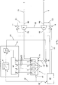
- FIG. 4 shows a further example of a proposed internal combustion engine 1 in a schematic block diagram.
- the internal combustion engine 1 is a mixture-supercharged gas engine in which the air supply pipe 5 is equipped with a mixer 13.
- a mixer outlet 13a of the mixer 13 opens into the air supply line 5, via which exiting from the mixer outlet 13a fuel-air mixture as charge air A is introduced into the combustion chambers 2.
- a mixer bypass valve 16 for bypassing the mixer 19 in a mixer bypass line 17 which connects the air line 15 directly to the mixer outlet 13a is arranged as an adjusting device, whereby a valve position of the mixer bypass valve is changed 16 a control signal from the control device 19 via a control line 22 to the mixer bypass valve 16 can be notified.
- a throttle valve 7 is arranged in the air supply line 5 as a further adjusting device, wherein for changing a position of the throttle valve 7, a control signal from the control device 19 via a control line 22 to the throttle valve 7 is notified.
- FIG. 5 shows another example of an internal combustion engine 1 designed as a mixture-charged gas engine, in which the air supply line 5 is equipped with a mixer 13.
- a fuel valve 18 is arranged in the fuel line 14 as a setting device, wherein for changing a valve position of the fuel valve 18, a control signal from the control device 19 via a control line 22 to the fuel valve 18 can be reported.
- FIG. 6 shows another example of an air-charged internal combustion engine 1.
- the combustion chambers 2 of the internal combustion engine 1 are supplied with charge air A in the form of compressed air L via an air supply line 5 and fuel G via a fuel supply line 31.
- the fuel supply line 31 is equipped with at least one Brennstoffdosierventil 28. It may preferably be provided that a fuel metering valve 28 is provided for each combustion chamber 2, in order to enable a cylinder-specific fuel metering. For the sake of clarity, only one fuel metering valve 28 has been shown in the figures, but of course each cylinder is associated with at least one such fuel metering valve.
- the at least one Brennstoffdosierventil 28 the adjusting device, wherein for changing a valve position of the at least one Brennstoffdosierventils 28, a control signal from the control device 19 via a control line 22 to the at least one Brennstoffdosierventil 28 is notified.
- a power controller 29 provided in this example detects the power P of the internal combustion engine 1 reported by a power measuring device 21 via a signal line 20 and counteracts a power change by providing control signals to a compressor bypass valve 6 and / or an exhaust gas turbine bypass valve 11 via corresponding lines 30 reports.
- the boost pressure p a of the charge air A is changed.
- FIG. 7 shows another example of a mixture-supercharged internal combustion engine 1, which similar to the internal combustion engine 1 of FIG. 6 equipped with a power regulator 29.
- the charge air A supplied to the combustion chambers 2 via the air supply line 5 in this example is a fuel-air mixture formed in a mixer 13, which comprises air L and fuel G.
- the mixer 13 is arranged in the air supply line 5, wherein a fuel line 14 for introducing the fuel G and an air line 15 for introducing the air L into the mixer 13 open and a mixer outlet 13 a of the mixer 13 opens into the air supply line 5.
- the fuel-air ratio of the fuel-air mixture in the form of the charge air A is changed. This is done by changing the valve position of a mixer bypass valve 16, which is arranged to bypass the mixer 13 in an air line 15 directly to the mixer outlet 13a connecting mixer-bypass line 17.
- the power controller 29 counteracts in this example of such a change in performance by reporting via a corresponding line 30, a control signal to a arranged in the air supply line 5 throttle valve 7.
- a control signal to a arranged in the air supply line 5 throttle valve 7.
- FIG. 8 shows another example of a mixture-supercharged internal combustion engine 1, which like the internal combustion engine 1 of the FIG. 7 equipped with a power regulator 29.
- a variable valve drive 32 is provided as adjusting device, via which the at least one combustion chamber supplied amount of air can be varied.
- a power controller 29 detects the power P of the internal combustion engine 1 reported by a power measuring device 21 via a signal line 20 and acts counteracts a change in power by 30 signal signals to the variable valve train 32 via signal lines.
- the valve opening times and / or the valve lift curves and / or the spread of intake and exhaust valves can be varied and thereby the amount (the volume) of the charge air A flowing into the combustion chamber can be varied. If, for example, the power output by the internal combustion engine 1 must be increased, the power controller 29 sends a signal to the variable valve train 32 that the amount of charge air A to be admitted into at least one of the combustion chambers 2 must be increased.
- variable valve train 32 may be provided for all previously shown configurations.
- FIG. 8 shows only one possible variant.
- 32 can be dispensed with a throttle valve when using a variable valve train.
- the dashed line PEX shows an exemplary course of a polytropic extrapolation. As explained in the description above, from a measured value for a cylinder pressure or an averaging of a plurality of values from a crank angle range via polytropic extrapolation to any point of the compression curve can be expected.
- the curve PEX is deliberately drawn slightly offset from the cylinder pressure curve for better distinctness, but of course runs congruently with the cylinder pressure curve.
Landscapes
- Engineering & Computer Science (AREA)
- Chemical & Material Sciences (AREA)
- Combustion & Propulsion (AREA)
- Mechanical Engineering (AREA)
- General Engineering & Computer Science (AREA)
- Chemical Kinetics & Catalysis (AREA)
- General Chemical & Material Sciences (AREA)
- Oil, Petroleum & Natural Gas (AREA)
- Output Control And Ontrol Of Special Type Engine (AREA)
- Combined Controls Of Internal Combustion Engines (AREA)
- Electrical Control Of Air Or Fuel Supplied To Internal-Combustion Engine (AREA)
Claims (22)
- Procédé de fonctionnement d'un moteur à combustion interne (1), plus particulièrement d'un moteur à gaz, avec au moins une chambre de combustion (2), à laquelle un air d'alimentation (A) avec une pression d'admission modifiable (pa) et / ou une quantité d'air d'alimentation modifiable est amené, dans lequel à partir d'au moins une valeur mesurée (pc) d'un capteur (3) disposé dans au moins une chambre de combustion (2) est déterminée une valeur de pression de cylindre (pi), caractérisé en ce que la valeur de pression de cylindre (pi) est réglée par modification de la pression d'admission (pa) et / ou par modification de la quantité d'air d'alimentation comme variable(s) réglante(s) sur une valeur théorique de pression de cylindre (ps), dans lequel la valeur théorique de pression de cylindre (ps) est choisie en fonction d'une puissance (P) du moteur à combustion interne (1), dans lequel la au moins une valeur mesurée (pc) est déterminée avant un allumage dans la chambre de combustion (2), de préférence dans une zone d'un angle de vilebrequin de 30 à 55 degrés environ avant un point mort haut d'un piston limitant la chambre de combustion (2), plus particulièrement de préférence avec un angle de vilebrequin de 35 degrés environ avant le point mort haut du piston ou avec un angle de vilebrequin de 49 degrés environ avant le point mort haut du piston.
- Procédé selon la revendication 1, caractérisé en ce que au moins deux, de préférence toutes les chambres de combustion (2) du moteur à combustion interne (1) sont à chaque fois équipées d'un capteur (3) pour déterminer la pression de cylindre, dans lequel à chaque fois à partir d'au moins une valeur mesurée (pc) d'un capteur (3) est déterminée une valeur de pression individuelle par cylindre de la chambre de combustion concernée (2), dans lequel est déterminée la valeur de pression de cylindre (pi) à partir des valeurs de pression individuelles par cylindre des chambres de combustion (2).
- Procédé selon la revendication 2, caractérisé en ce que comme valeur de pression de cylindre (pi) est déterminée la valeur médiane ou la valeur moyenne arithmétique des valeurs de pression individuelles par cylindre des chambres de combustion (2).
- Procédé selon l'une des revendications 1 à 3, caractérisé en ce que la valeur théorique de pression de cylindre respective (ps) est prédéfinie à partir d'une caractéristique de fonctionnement (4), qui renferme une affectation de la valeur théorique de pression de cylindre (ps) à une puissance (P) du moteur à combustion interne (1) en fonction de la puissance (P) du moteur à combustion interne pour des valeurs essentiellement constantes pour des émissions d'oxyde d'azote.
- Procédé selon l'une des revendications 1 à 4, caractérisé en ce que l'air d'alimentation (A) est amené à la au moins une chambre de combustion (2) par une conduite d'amenée d'air (5), dans lequel la pression d'admission (pa) est modifiée par réglage d'au moins un dispositif de réglage (6, 7) disposé dans la conduite d'amenée d'air (5), de préférence par réglage d'une soupape de dérivation de compresseur (6) et / ou d'une soupape d'étranglement (7).
- Procédé selon l'une des revendications 1 à 5, caractérisé en ce que l'air d'alimentation (A) est amené à la au moins une chambre de combustion (2) par une conduite d'amenée d'air (5), dans lequel la quantité d'air d'alimentation est modifiée par réglage d'une commande de soupape variable (32).
- Procédé selon l'une des revendications 1 à 6, caractérisé en ce que l'air d'alimentation (A) est amené à la au moins une chambre de combustion (2) par une conduite d'amenée d'air (5) équipée d'un compresseur (8), dans lequel le compresseur (8) est couplé à une turbine à gaz d'échappement (9) dans une conduite de gaz d'échappement (10) du moteur à combustion interne (1), dans lequel la pression d'admission (pa) est modifiée par déplacement des aubes de turbine de la turbine à gaz d'échappement (9) ou par réglage d'une soupape de dérivation de turbines à gaz d'échappement (11) dans la conduite de gaz d'échappement (10), dans lequel la soupape de dérivation de turbines à gaz d'échappement (11), pour contourner la turbine à gaz d'échappement (9), est disposée dans une conduite de dérivation de gaz d'échappement (12), qui relie une entrée de turbine à gaz d'échappement (9a) directement à une sortie de turbine à gaz d'échappement (9b).
- Procédé selon l'une des revendications 1 à 7, caractérisé en ce qu'un mélange air-carburant comprenant l'air d'alimentation (A) est introduit dans la au moins une chambre de combustion (2), dans lequel l'air d'alimentation (pa) est modifié par ajustement d'un rapport air-carburant du mélange air-carburant, dans lequel lors et / ou après modification du rapport air-carburant du mélange air-carburant, la pression d'admission (pa) de l'air d'alimentation (A) est réglée en fonction de la puissance (P) du moteur à combustion interne.
- Procédé selon la revendication 8, caractérisé en ce que comme mélange air-carburant est amené l'air d'alimentation (A) à la au moins une chambre de combustion (2) par une conduite d'amenée d'air (5) équipée d'un mélangeur (13), dans lequel une conduite de carburant (14) pour l'introduction de carburant (G) et une conduite d'air (15) pour l'introduction d'air (L) débouchent dans le mélangeur (13) et une sortie de mélangeur (13a) du mélangeur (13) débouche dans la conduite d'amenée d'air (5), dans lequel le rapport air-carburant de l'air d'alimentation (A) est modifié par réglage d'une soupape de dérivation de mélangeur (16), dans lequel la soupape de dérivation de mélangeur (16) pour contourner le mélangeur (13) est disposée dans une conduite de dérivation de mélangeur (17) reliant directement la conduite d'air (15) à la sortie de mélangeur (13a).
- Procédé selon la revendication 8 ou 9, caractérisé en ce que comme mélange air-carburant est amené l'air d'alimentation (A) à la au moins une chambre de combustion (2) par une conduite d'amenée d'air (5) équipée d'un mélangeur (13), dans lequel une conduite de carburant (14) pour l'introduction de carburant (G) et une conduite d'air (15) pour l'introduction d'air (L) débouchent dans le mélangeur (13) et une sortie de mélangeur (13a) du mélangeur (13) débouche dans la conduite d'amenée d'air (5), dans lequel le rapport air-carburant de l'air d'alimentation (A) est modifié par réglage d'une soupape de carburant (18) disposée dans la conduite de carburant (14), dans lequel, par une modification de la position de la soupape de carburant (18), la quantité de carburant amenée au mélangeur (13) par la conduite de carburant (14) est modifiée.
- Procédé selon la revendication 8, caractérisé en ce que le mélange air-carburant comprend l'air d'alimentation (A) et un carburant (G), dans lequel l'air d'alimentation (A) est amené, par une conduite d'amenée d'air (5) et le carburant (G) par une conduite d'amenée de carburant (31) équipée d'au moins une soupape de dosage de carburant (28), à la au moins une chambre de combustion (2), dans lequel le rapport air-carburant du mélange air-carburant est modifié par modification d'une position de la au moins une soupape de dosage du carburant (28).
- Dispositif de réglage (19) pour régler une valeur de pression de cylindre (pi) d'un moteur à combustion interne (1) équipé d'au moins une chambre de combustion (2), dans lequel par une conduite d'amenée d'air (5) du moteur à combustion interne (1) peut être introduit un air d'alimentation (A) avec une pression d'admission modifiable (pa) et / ou une quantité d'air d'alimentation modifiable dans la au moins une chambre de combustion (2), dans lequel la au moins une chambre de combustion (2) est équipée d'un capteur (3) pour déterminer la pression de cylindre, dans lequel au moins une valeur mesurée (pc) du capteur (3) peut être signalée par un câble de signalisation (20) du dispositif de réglage (19), dans lequel un dispositif de mesure de puissance (21) pour déterminer une puissance (P) du moteur à combustion interne (1) est prévu, dans lequel la puissance (P) peut être signalée par un autre câble de signalisation (20) du dispositif de réglage (19), caractérisé en ce que la au moins une valeur mesurée (pc) est déterminée avant un allumage dans la chambre de combustion (2), dans lequel le dispositif de réglage (19) détermine la valeur de pression de cylindre (pi) à partir de la au moins une valeur mesurée (pc) du capteur (3), dans lequel le dispositif de réglage (19) lors d'un écart de la valeur de pression de cylindre (pi) d'une valeur théorique de pression de cylindre (ps) dépendante de la puissance (P) du moteur à combustion interne (1)- pour modifier la pression d'admission (pa), indique un signal correcteur à au moins un dispositif de réglage (6, 7, 11, 16, 18, 28) par une conduite de commande (22) jusqu'à ce que la valeur de pression de cylindre (pi) et la valeur théorique de pression de cylindre (ps) coïncident, dans lequel de préférence le au moins un dispositif de réglage (6, 7, 11, 16, 18, 28) est disposé dans la conduite d'amenée d'air (5) ou dans une conduite de gaz d'échappement (10) du moteur à combustion interne (1) et / ou- pour modifier la quantité d'air d'alimentation, indique un signal correcteur à une commande de soupape variable (32) par une conduite de commande (22), jusqu'à ce que la valeur de pression de cylindre (pi) et la valeur théorique de cylindre (ps) coïncident.
- Moteur à combustion interne (1), plus particulièrement moteur à gaz, avec au moins une chambre de combustion (2) équipée d'un capteur (3) pour déterminer la pression de cylindre et avec un dispositif de réglage (19) selon la revendication 12.
- Moteur à combustion interne selon la revendication 13, caractérisé en ce que dans la conduite d'amenée d'air (5) est disposée, comme dispositif de réglage, une soupape d'étranglement (7), dans lequel, pour modifier une position de la soupape d'étranglement (7), un signal correcteur du dispositif de réglage (19) peut être indiqué à la soupape d'étranglement (7) par une conduite de commande (22).
- Moteur à combustion interne selon la revendication 13 ou 14, caractérisé en ce que dans la conduite d'amenée d'air (5) est disposé un compresseur (8) pour comprimer l'air d'alimentation (A), dans lequel le compresseur (8) est couplé à une turbine à gaz d'échappement (9) dans une conduite de gaz d'échappement (10) du moteur à combustion interne (1).
- Moteur à combustion interne selon la revendication 15, caractérisé en ce que comme dispositif de réglage est disposé une soupape de dérivation de compresseur (6) pour contourner le compresseur (8) dans une conduite de dérivation de compresseur (23), qui relie une entrée de compresseur (8a) directement à une sortie de compresseur (8b), dans lequel pour modifier une position de soupape de la soupape de dérivation de compresseur (6), un signal correcteur du dispositif de réglage (19) peut être indiqué à la soupape de dérivation de compresseur (6) par une conduite de commande (22).
- Moteur à combustion interne selon la revendication 15 ou 16, caractérisé en ce que la turbine à gaz d'échappement (9) présente des aubes de turbine réglables comme dispositif de réglage, dans lequel pour modifier une géométrie des aubes de turbine, un signal correcteur du dispositif de réglage (19) peut être indiqué à la turbine à gaz d'échappement (9) par une conduite de commande (22).
- Moteur à combustion interne selon l'une des revendications 15 à 17, caractérisé en ce que comme dispositif de réglage est disposée, pour contourner la turbine à gaz d'échappement (9), une soupape de dérivation de turbine à gaz d'échappement (11) dans une conduite de dérivation de gaz d'échappement (12), qui relie une entrée de turbine de gaz d'échappement (9a) directement à une sortie de turbine à gaz d'échappement (9b), dans lequel pour modifier une position de soupape de la soupape de dérivation de turbines à gaz d'échappement (11), un signal correcteur du dispositif de réglage (19) peut être indiqué à la soupape de dérivation de turbines à gaz d'échappement (11) par une conduite de commande (22).
- Moteur à combustion interne selon l'une des revendications 13 à 18, caractérisé en ce que dans la conduite d'amenée d'air (5) est disposé un mélangeur (13), dans lequel une conduite de carburant (14) pour l'introduction de carburant (G) et une conduite d'air (15) pour l'introduction d'air (L) débouchent dans le mélangeur (13) et une sortie de mélangeur (13a) du mélangeur (13) débouche dans la conduite d'amenée d'air (5).
- Moteur à combustion interne selon la revendication 19, caractérisé en ce que comme dispositif de réglage est disposée une soupape de dérivation de mélangeur (16) pour contourner le mélangeur (13) dans une conduite de dérivation de mélangeur (17) reliant la conduite d'air (15) directement à la sortie de mélangeur (13a), dans lequel pour modifier une position de soupape de la soupape de dérivation de mélangeur (16), un signal correcteur du dispositif de réglage (19) peut être indiqué à la soupape de dérivation de mélangeur (16) par une conduite de commande (22).
- Moteur à combustion interne selon la revendication 19 ou 20, caractérisé en ce que comme dispositif de réglage est disposée une soupape de carburant (18) dans la conduite de carburant (14), dans lequel pour modifier une position de soupape de la soupape de carburant (18), un signal correcteur du dispositif de réglage (19) peut être indiqué à la soupape de carburant (18) par une conduite de commande (22).
- Moteur à combustion interne selon l'une des revendications 13 à 18, caractérisé en ce qu'un carburant (G) peut être introduit dans la au moins une chambre de combustion (2) par une conduite d'amenée de carburant (31), dans lequel comme dispositif de réglage est disposée au moins une soupape de dosage de carburant (28) dans la conduite d'amenée de carburant (31), dans lequel pour modifier une position de soupape de la au moins une soupape de dosage de carburant (28), un signal correcteur du dispositif de réglage (19) peut être indiqué à la au moins une soupape de dosage de carburant (28) par une conduite de commande (22).
Applications Claiming Priority (1)
| Application Number | Priority Date | Filing Date | Title |
|---|---|---|---|
| ATA120/2014A AT515499B1 (de) | 2014-02-20 | 2014-02-20 | Verfahren zum Betreiben einer Brennkraftmaschine |
Publications (2)
| Publication Number | Publication Date |
|---|---|
| EP2910755A1 EP2910755A1 (fr) | 2015-08-26 |
| EP2910755B1 true EP2910755B1 (fr) | 2018-08-15 |
Family
ID=52464118
Family Applications (1)
| Application Number | Title | Priority Date | Filing Date |
|---|---|---|---|
| EP15000277.2A Active EP2910755B1 (fr) | 2014-02-20 | 2015-01-30 | Procédé destiné au fonctionnement d'un moteur à combustion interne |
Country Status (6)
| Country | Link |
|---|---|
| US (1) | US10161320B2 (fr) |
| EP (1) | EP2910755B1 (fr) |
| JP (1) | JP2015155695A (fr) |
| KR (1) | KR102234973B1 (fr) |
| CN (1) | CN104863729B (fr) |
| AT (1) | AT515499B1 (fr) |
Families Citing this family (10)
| Publication number | Priority date | Publication date | Assignee | Title |
|---|---|---|---|---|
| AT517216B1 (de) | 2015-06-30 | 2016-12-15 | Ge Jenbacher Gmbh & Co Og | Brennkraftmaschine mit einer Regeleinrichtung |
| AT518102B1 (de) * | 2015-12-29 | 2017-10-15 | Ge Jenbacher Gmbh & Co Og | Zustandsbestimmung eines Filtermoduls |
| US10077727B2 (en) * | 2016-01-13 | 2018-09-18 | GM Global Technology Operations LLC | Engine control systems and methods for nitrogen oxide reduction |
| DE102018206295A1 (de) * | 2018-04-24 | 2019-10-24 | Volkswagen Aktiengesellschaft | Verfahren zum Betreiben einer mit Gas betriebenen Brennkraftmaschine mit VTG-Lader |
| DE102018206294A1 (de) * | 2018-04-24 | 2019-10-24 | Volkswagen Aktiengesellschaft | Verfahren zum Betreiben einer mit Gas betriebenen Brennkraftmaschine mit VTG-Lader |
| EP3935272B1 (fr) * | 2019-03-04 | 2024-06-26 | Innio Jenbacher GmbH & Co OG | Moteur à combustion interne et procédé de fonctionnement d'un moteur à combustion interne |
| EP3839226A1 (fr) * | 2019-12-20 | 2021-06-23 | ABB Schweiz AG | Système d'alimentation mélangé pour moteur à combustion interne à régulation quantitative du rapport de mélange |
| CN112523882B (zh) * | 2020-11-09 | 2023-04-28 | 广西玉柴船电动力有限公司 | 燃气发动机进气压力闭环的燃料控制方法 |
| EP4219922A1 (fr) * | 2022-01-31 | 2023-08-02 | Winterthur Gas & Diesel Ltd. | Dispositif et procédé de fonctionnement d'un grand moteur |
| EP4698764A1 (fr) * | 2023-04-20 | 2026-02-25 | Innio Jenbacher GmbH & Co OG | Moteur à combustion interne |
Citations (1)
| Publication number | Priority date | Publication date | Assignee | Title |
|---|---|---|---|---|
| DE19736131C1 (de) * | 1997-08-20 | 1998-10-08 | Daimler Benz Ag | Verfahren zur Regelung eines Kompressionsdruckes in einer Hubkolben-Brennkraftmaschine |
Family Cites Families (33)
| Publication number | Priority date | Publication date | Assignee | Title |
|---|---|---|---|---|
| JPH0224929Y2 (fr) * | 1984-12-29 | 1990-07-09 | ||
| AT384279B (de) | 1986-03-05 | 1987-10-27 | Jenbacher Werke Ag | Einrichtung zur regelung des verbrennungsluftverh|ltnisses bei einem gasmotor mit magerer betriebsweise |
| US6029109A (en) * | 1996-04-15 | 2000-02-22 | Siemens Automotive S.A. | Method for calculating the torque of an internal combustion engine |
| US6425373B1 (en) * | 1999-08-04 | 2002-07-30 | Ford Global Technologies, Inc. | System and method for determining engine control parameters based on engine torque |
| US6234141B1 (en) * | 2000-01-11 | 2001-05-22 | Ford Global Technologies, Inc. | Method of controlling intake manifold pressure during startup of a direct injection engine |
| DE10006161A1 (de) * | 2000-02-11 | 2001-08-23 | Bosch Gmbh Robert | Verfahren und Einrichtung zur Bestimmung zylinderindividueller Unterschiede einer Steuergröße bei einer mehrzylindrigen Brennkraftmaschine |
| DE10028886A1 (de) * | 2000-06-10 | 2001-12-13 | Volkswagen Ag | Verfahren und Vorrichtung zum Überwachen des Betriebs eines Verbrennungsmotors |
| US6360726B1 (en) * | 2000-07-31 | 2002-03-26 | General Motors Corporation | Fuel volatility detection and compensation during cold engine start |
| US6668812B2 (en) * | 2001-01-08 | 2003-12-30 | General Motors Corporation | Individual cylinder controller for three-cylinder engine |
| JP2003097314A (ja) | 2001-09-20 | 2003-04-03 | Tokyo Gas Co Ltd | 希薄燃焼ガスエンジン及びその制御方法。 |
| JP2003328764A (ja) | 2002-05-09 | 2003-11-19 | Mitsubishi Heavy Ind Ltd | ブースト圧力制御装置を備えたガスエンジン及びその運転方法 |
| US6935313B2 (en) * | 2002-05-15 | 2005-08-30 | Caterpillar Inc | System and method for diagnosing and calibrating internal combustion engines |
| IL159651A0 (en) * | 2003-12-30 | 2004-06-01 | Nexense Ltd | Method and apparatus for measuring torque |
| US7072758B2 (en) * | 2004-03-19 | 2006-07-04 | Ford Global Technologies, Llc | Method of torque control for an engine with valves that may be deactivated |
| DE102004022593B4 (de) * | 2004-05-07 | 2007-12-27 | Siemens Ag | Verfahren und Vorrichtung zum Steuern einer Brennkraftmaschine |
| DE102004033231A1 (de) * | 2004-07-08 | 2006-02-02 | Robert Bosch Gmbh | Verfahren zum Betreiben einer Brennkraftmaschine mit mehreren Zylinderbänken |
| US20060064232A1 (en) * | 2004-09-23 | 2006-03-23 | General Motors Corporation | System and method for controlling vehicle performance |
| FR2878575B1 (fr) * | 2004-11-30 | 2007-04-06 | Peugeot Citroen Automobiles Sa | Procede de regulation d'un systeme d'admission d'un moteur a combustion interne et vehicule automobile pour la mise en oeuvre du procede |
| US7027910B1 (en) * | 2005-01-13 | 2006-04-11 | General Motors Corporation | Individual cylinder controller for four-cylinder engine |
| JP2007211729A (ja) | 2006-02-13 | 2007-08-23 | Mitsubishi Heavy Ind Ltd | 4サイクルエンジン |
| US20080060861A1 (en) * | 2006-09-12 | 2008-03-13 | Andrew Baur | Entertainment vehicle that simulates a vehicle with an internal combustion engine and multiple gear ratios |
| DE102007052476B4 (de) * | 2007-11-02 | 2020-03-26 | Volkswagen Ag | Verfahren zum Betreiben einer Brennkraftmaschine |
| JP2009133284A (ja) | 2007-11-30 | 2009-06-18 | Mitsubishi Heavy Ind Ltd | 内燃機関の燃焼診断方法および燃焼診断装置 |
| JP4738426B2 (ja) | 2008-02-07 | 2011-08-03 | 三菱重工業株式会社 | ガスエンジンの制御方法及び装置 |
| DE102008025549B4 (de) * | 2008-05-28 | 2010-07-01 | Continental Automotive Gmbh | Verfahren und Vorrichtung zum Betreiben einer Brennkraftmaschine |
| AT508010B1 (de) | 2008-09-26 | 2010-10-15 | Ge Jenbacher Gmbh & Co Ohg | Brennkraftmaschine |
| US8695567B2 (en) * | 2010-10-29 | 2014-04-15 | GM Global Technology Operations LLC | Method and apparatus for estimating engine operating parameters |
| AT511001B1 (de) | 2011-01-18 | 2013-11-15 | Ge Jenbacher Gmbh & Co Ohg | Verfahren zum betreiben einer über wenigstens zwei zylinder verfügenden brennkraftmaschine |
| JP5904802B2 (ja) | 2012-01-19 | 2016-04-20 | 大阪瓦斯株式会社 | ガスエンジン |
| AT513359B1 (de) * | 2012-08-17 | 2014-07-15 | Ge Jenbacher Gmbh & Co Og | Verfahren zum Betreiben einer Brennkraftmaschine |
| AT513139B1 (de) | 2012-08-17 | 2014-02-15 | Ge Jenbacher Gmbh & Co Og | Verfahren zum Betreiben einer Brennkraftmaschine |
| DE102012021778B4 (de) * | 2012-11-06 | 2016-03-10 | Mtu Friedrichshafen Gmbh | Gemischaufgeladener Gasmotor und Verfahren zur Kompensation von Liefergradabweichungen in einem gemischaufgeladenen Gasmotor |
| US10041448B2 (en) * | 2014-06-17 | 2018-08-07 | Ford Global Technologies, Llc | Systems and methods for boost control |
-
2014
- 2014-02-20 AT ATA120/2014A patent/AT515499B1/de active
-
2015
- 2015-01-30 EP EP15000277.2A patent/EP2910755B1/fr active Active
- 2015-01-30 US US14/610,109 patent/US10161320B2/en active Active
- 2015-02-13 KR KR1020150022262A patent/KR102234973B1/ko active Active
- 2015-02-16 JP JP2015027194A patent/JP2015155695A/ja active Pending
- 2015-02-16 CN CN201510083115.6A patent/CN104863729B/zh active Active
Patent Citations (1)
| Publication number | Priority date | Publication date | Assignee | Title |
|---|---|---|---|---|
| DE19736131C1 (de) * | 1997-08-20 | 1998-10-08 | Daimler Benz Ag | Verfahren zur Regelung eines Kompressionsdruckes in einer Hubkolben-Brennkraftmaschine |
Also Published As
| Publication number | Publication date |
|---|---|
| US10161320B2 (en) | 2018-12-25 |
| EP2910755A1 (fr) | 2015-08-26 |
| KR20150098580A (ko) | 2015-08-28 |
| CN104863729B (zh) | 2018-08-14 |
| AT515499B1 (de) | 2016-01-15 |
| JP2015155695A (ja) | 2015-08-27 |
| US20150233312A1 (en) | 2015-08-20 |
| CN104863729A (zh) | 2015-08-26 |
| KR102234973B1 (ko) | 2021-04-01 |
| AT515499A1 (de) | 2015-09-15 |
Similar Documents
| Publication | Publication Date | Title |
|---|---|---|
| EP2910755B1 (fr) | Procédé destiné au fonctionnement d'un moteur à combustion interne | |
| AT511001B1 (de) | Verfahren zum betreiben einer über wenigstens zwei zylinder verfügenden brennkraftmaschine | |
| AT513359B1 (de) | Verfahren zum Betreiben einer Brennkraftmaschine | |
| DE69330313T2 (de) | Motorkontrolleinheit | |
| DE102013215000B4 (de) | Innenverbrennungsmotor-Waste-Gate-Ventil-Steuervorrichtung | |
| DE3918772C2 (fr) | ||
| DE3341200C2 (de) | Verfahren und Anordnung zum Regeln des Luft/Brennstoff-Verhältnisses bei einem Verbrennungsmotor | |
| EP2449234B1 (fr) | Procédé de régulation d'un moteur à gaz | |
| EP2977596B1 (fr) | Moteur a combustion interne dote d'un dispositif de reglage | |
| DE112006003029B4 (de) | System und Verfahren zum Steuern des Zylindergleichgewichts für einen Motor unter Anwendung einer zylinderdruckbasierten Mehrgrößenregelung | |
| DE102016103417B4 (de) | Steuervorrichtung und steuerverfahren für eine brennkraftmaschine | |
| DE102015201061A1 (de) | Pumpverlustberechnungsvorrichtung für Verbrennungsmotor | |
| EP1567760A1 (fr) | Procede pour commander un moteur a combustion interne a injection directe de carburant | |
| DE102010062198B4 (de) | Verfahren und Steuereinrichtung zum Betrieb eines Otto-Gasmotors | |
| DE4006294C2 (de) | Verfahren zur Einstellung der Leerlaufdrehzahl | |
| EP1158149A1 (fr) | Dispositif pour le calcul du rapport air-carburant dans un moteur à gaz | |
| EP1431557A2 (fr) | Procédé d'équilibrage des cylindres | |
| DE102014214438B3 (de) | Verfahren zur Steuerung der Kraftstoffzufuhr zur Einstellung eines gewünschten Luft-Kraftstoff-Verhältnisses in einem Zylinder eines Verbrennungsmotors | |
| AT517216B1 (de) | Brennkraftmaschine mit einer Regeleinrichtung | |
| DE19730973C2 (de) | Verfahren zum Steuern einer Brennkraftmaschine | |
| DE102007012340B3 (de) | Verfahren zum Ermitteln und Einregeln des Luftmassenstroms im Saugrohr eines Verbrennungsmotors sowie zugehöriges Steuergerät | |
| EP3935272B1 (fr) | Moteur à combustion interne et procédé de fonctionnement d'un moteur à combustion interne | |
| DE102017205034B4 (de) | Verfahren zum Betreiben einer Brennkraftmaschine und Brennkraftmaschine | |
| DE1476003C (de) | Brennkraftmaschine zum Antrieb eines Generators mit einem Lader | |
| DE102015216099A1 (de) | Verfahren und Vorrichtung zum Betreiben eines Verbrennungsmotors mit Abgasrückführung |
Legal Events
| Date | Code | Title | Description |
|---|---|---|---|
| PUAI | Public reference made under article 153(3) epc to a published international application that has entered the european phase |
Free format text: ORIGINAL CODE: 0009012 |
|
| AK | Designated contracting states |
Kind code of ref document: A1 Designated state(s): AL AT BE BG CH CY CZ DE DK EE ES FI FR GB GR HR HU IE IS IT LI LT LU LV MC MK MT NL NO PL PT RO RS SE SI SK SM TR |
|
| AX | Request for extension of the european patent |
Extension state: BA ME |
|
| 17P | Request for examination filed |
Effective date: 20160219 |
|
| RBV | Designated contracting states (corrected) |
Designated state(s): AL AT BE BG CH CY CZ DE DK EE ES FI FR GB GR HR HU IE IS IT LI LT LU LV MC MK MT NL NO PL PT RO RS SE SI SK SM TR |
|
| RIC1 | Information provided on ipc code assigned before grant |
Ipc: F02D 35/02 20060101AFI20160628BHEP Ipc: F02D 41/00 20060101ALI20160628BHEP |
|
| STAA | Information on the status of an ep patent application or granted ep patent |
Free format text: STATUS: EXAMINATION IS IN PROGRESS |
|
| 17Q | First examination report despatched |
Effective date: 20161222 |
|
| GRAP | Despatch of communication of intention to grant a patent |
Free format text: ORIGINAL CODE: EPIDOSNIGR1 |
|
| STAA | Information on the status of an ep patent application or granted ep patent |
Free format text: STATUS: GRANT OF PATENT IS INTENDED |
|
| INTG | Intention to grant announced |
Effective date: 20180309 |
|
| GRAS | Grant fee paid |
Free format text: ORIGINAL CODE: EPIDOSNIGR3 |
|
| GRAA | (expected) grant |
Free format text: ORIGINAL CODE: 0009210 |
|
| STAA | Information on the status of an ep patent application or granted ep patent |
Free format text: STATUS: THE PATENT HAS BEEN GRANTED |
|
| AK | Designated contracting states |
Kind code of ref document: B1 Designated state(s): AL AT BE BG CH CY CZ DE DK EE ES FI FR GB GR HR HU IE IS IT LI LT LU LV MC MK MT NL NO PL PT RO RS SE SI SK SM TR |
|
| REG | Reference to a national code |
Ref country code: CH Ref legal event code: EP Ref country code: GB Ref legal event code: FG4D Free format text: NOT ENGLISH Ref country code: AT Ref legal event code: REF Ref document number: 1030051 Country of ref document: AT Kind code of ref document: T Effective date: 20180815 |
|
| REG | Reference to a national code |
Ref country code: IE Ref legal event code: FG4D Free format text: LANGUAGE OF EP DOCUMENT: GERMAN |
|
| REG | Reference to a national code |
Ref country code: DE Ref legal event code: R096 Ref document number: 502015005398 Country of ref document: DE |
|
| REG | Reference to a national code |
Ref country code: NL Ref legal event code: MP Effective date: 20180815 |
|
| REG | Reference to a national code |
Ref country code: LT Ref legal event code: MG4D |
|
| PG25 | Lapsed in a contracting state [announced via postgrant information from national office to epo] |
Ref country code: SE Free format text: LAPSE BECAUSE OF FAILURE TO SUBMIT A TRANSLATION OF THE DESCRIPTION OR TO PAY THE FEE WITHIN THE PRESCRIBED TIME-LIMIT Effective date: 20180815 Ref country code: BG Free format text: LAPSE BECAUSE OF FAILURE TO SUBMIT A TRANSLATION OF THE DESCRIPTION OR TO PAY THE FEE WITHIN THE PRESCRIBED TIME-LIMIT Effective date: 20181115 Ref country code: NL Free format text: LAPSE BECAUSE OF FAILURE TO SUBMIT A TRANSLATION OF THE DESCRIPTION OR TO PAY THE FEE WITHIN THE PRESCRIBED TIME-LIMIT Effective date: 20180815 Ref country code: GR Free format text: LAPSE BECAUSE OF FAILURE TO SUBMIT A TRANSLATION OF THE DESCRIPTION OR TO PAY THE FEE WITHIN THE PRESCRIBED TIME-LIMIT Effective date: 20181116 Ref country code: NO Free format text: LAPSE BECAUSE OF FAILURE TO SUBMIT A TRANSLATION OF THE DESCRIPTION OR TO PAY THE FEE WITHIN THE PRESCRIBED TIME-LIMIT Effective date: 20181115 Ref country code: RS Free format text: LAPSE BECAUSE OF FAILURE TO SUBMIT A TRANSLATION OF THE DESCRIPTION OR TO PAY THE FEE WITHIN THE PRESCRIBED TIME-LIMIT Effective date: 20180815 Ref country code: LT Free format text: LAPSE BECAUSE OF FAILURE TO SUBMIT A TRANSLATION OF THE DESCRIPTION OR TO PAY THE FEE WITHIN THE PRESCRIBED TIME-LIMIT Effective date: 20180815 Ref country code: FI Free format text: LAPSE BECAUSE OF FAILURE TO SUBMIT A TRANSLATION OF THE DESCRIPTION OR TO PAY THE FEE WITHIN THE PRESCRIBED TIME-LIMIT Effective date: 20180815 Ref country code: IS Free format text: LAPSE BECAUSE OF FAILURE TO SUBMIT A TRANSLATION OF THE DESCRIPTION OR TO PAY THE FEE WITHIN THE PRESCRIBED TIME-LIMIT Effective date: 20181215 |
|
| PG25 | Lapsed in a contracting state [announced via postgrant information from national office to epo] |
Ref country code: LV Free format text: LAPSE BECAUSE OF FAILURE TO SUBMIT A TRANSLATION OF THE DESCRIPTION OR TO PAY THE FEE WITHIN THE PRESCRIBED TIME-LIMIT Effective date: 20180815 Ref country code: HR Free format text: LAPSE BECAUSE OF FAILURE TO SUBMIT A TRANSLATION OF THE DESCRIPTION OR TO PAY THE FEE WITHIN THE PRESCRIBED TIME-LIMIT Effective date: 20180815 Ref country code: AL Free format text: LAPSE BECAUSE OF FAILURE TO SUBMIT A TRANSLATION OF THE DESCRIPTION OR TO PAY THE FEE WITHIN THE PRESCRIBED TIME-LIMIT Effective date: 20180815 |
|
| PG25 | Lapsed in a contracting state [announced via postgrant information from national office to epo] |
Ref country code: IT Free format text: LAPSE BECAUSE OF FAILURE TO SUBMIT A TRANSLATION OF THE DESCRIPTION OR TO PAY THE FEE WITHIN THE PRESCRIBED TIME-LIMIT Effective date: 20180815 Ref country code: EE Free format text: LAPSE BECAUSE OF FAILURE TO SUBMIT A TRANSLATION OF THE DESCRIPTION OR TO PAY THE FEE WITHIN THE PRESCRIBED TIME-LIMIT Effective date: 20180815 Ref country code: CZ Free format text: LAPSE BECAUSE OF FAILURE TO SUBMIT A TRANSLATION OF THE DESCRIPTION OR TO PAY THE FEE WITHIN THE PRESCRIBED TIME-LIMIT Effective date: 20180815 Ref country code: RO Free format text: LAPSE BECAUSE OF FAILURE TO SUBMIT A TRANSLATION OF THE DESCRIPTION OR TO PAY THE FEE WITHIN THE PRESCRIBED TIME-LIMIT Effective date: 20180815 Ref country code: ES Free format text: LAPSE BECAUSE OF FAILURE TO SUBMIT A TRANSLATION OF THE DESCRIPTION OR TO PAY THE FEE WITHIN THE PRESCRIBED TIME-LIMIT Effective date: 20180815 Ref country code: PL Free format text: LAPSE BECAUSE OF FAILURE TO SUBMIT A TRANSLATION OF THE DESCRIPTION OR TO PAY THE FEE WITHIN THE PRESCRIBED TIME-LIMIT Effective date: 20180815 |
|
| REG | Reference to a national code |
Ref country code: DE Ref legal event code: R097 Ref document number: 502015005398 Country of ref document: DE |
|
| PG25 | Lapsed in a contracting state [announced via postgrant information from national office to epo] |
Ref country code: SK Free format text: LAPSE BECAUSE OF FAILURE TO SUBMIT A TRANSLATION OF THE DESCRIPTION OR TO PAY THE FEE WITHIN THE PRESCRIBED TIME-LIMIT Effective date: 20180815 Ref country code: DK Free format text: LAPSE BECAUSE OF FAILURE TO SUBMIT A TRANSLATION OF THE DESCRIPTION OR TO PAY THE FEE WITHIN THE PRESCRIBED TIME-LIMIT Effective date: 20180815 Ref country code: SM Free format text: LAPSE BECAUSE OF FAILURE TO SUBMIT A TRANSLATION OF THE DESCRIPTION OR TO PAY THE FEE WITHIN THE PRESCRIBED TIME-LIMIT Effective date: 20180815 |
|
| PLBE | No opposition filed within time limit |
Free format text: ORIGINAL CODE: 0009261 |
|
| STAA | Information on the status of an ep patent application or granted ep patent |
Free format text: STATUS: NO OPPOSITION FILED WITHIN TIME LIMIT |
|
| 26N | No opposition filed |
Effective date: 20190516 |
|
| PG25 | Lapsed in a contracting state [announced via postgrant information from national office to epo] |
Ref country code: SI Free format text: LAPSE BECAUSE OF FAILURE TO SUBMIT A TRANSLATION OF THE DESCRIPTION OR TO PAY THE FEE WITHIN THE PRESCRIBED TIME-LIMIT Effective date: 20180815 Ref country code: MC Free format text: LAPSE BECAUSE OF FAILURE TO SUBMIT A TRANSLATION OF THE DESCRIPTION OR TO PAY THE FEE WITHIN THE PRESCRIBED TIME-LIMIT Effective date: 20180815 |
|
| REG | Reference to a national code |
Ref country code: CH Ref legal event code: PL |
|
| PG25 | Lapsed in a contracting state [announced via postgrant information from national office to epo] |
Ref country code: LU Free format text: LAPSE BECAUSE OF NON-PAYMENT OF DUE FEES Effective date: 20190130 |
|
| REG | Reference to a national code |
Ref country code: BE Ref legal event code: MM Effective date: 20190131 |
|
| REG | Reference to a national code |
Ref country code: IE Ref legal event code: MM4A |
|
| PG25 | Lapsed in a contracting state [announced via postgrant information from national office to epo] |
Ref country code: BE Free format text: LAPSE BECAUSE OF NON-PAYMENT OF DUE FEES Effective date: 20190131 |
|
| PG25 | Lapsed in a contracting state [announced via postgrant information from national office to epo] |
Ref country code: LI Free format text: LAPSE BECAUSE OF NON-PAYMENT OF DUE FEES Effective date: 20190131 Ref country code: CH Free format text: LAPSE BECAUSE OF NON-PAYMENT OF DUE FEES Effective date: 20190131 |
|
| PG25 | Lapsed in a contracting state [announced via postgrant information from national office to epo] |
Ref country code: IE Free format text: LAPSE BECAUSE OF NON-PAYMENT OF DUE FEES Effective date: 20190130 |
|
| PG25 | Lapsed in a contracting state [announced via postgrant information from national office to epo] |
Ref country code: TR Free format text: LAPSE BECAUSE OF FAILURE TO SUBMIT A TRANSLATION OF THE DESCRIPTION OR TO PAY THE FEE WITHIN THE PRESCRIBED TIME-LIMIT Effective date: 20180815 |
|
| PG25 | Lapsed in a contracting state [announced via postgrant information from national office to epo] |
Ref country code: PT Free format text: LAPSE BECAUSE OF FAILURE TO SUBMIT A TRANSLATION OF THE DESCRIPTION OR TO PAY THE FEE WITHIN THE PRESCRIBED TIME-LIMIT Effective date: 20181215 Ref country code: MT Free format text: LAPSE BECAUSE OF FAILURE TO SUBMIT A TRANSLATION OF THE DESCRIPTION OR TO PAY THE FEE WITHIN THE PRESCRIBED TIME-LIMIT Effective date: 20180815 |
|
| REG | Reference to a national code |
Ref country code: AT Ref legal event code: MM01 Ref document number: 1030051 Country of ref document: AT Kind code of ref document: T Effective date: 20200130 |
|
| PG25 | Lapsed in a contracting state [announced via postgrant information from national office to epo] |
Ref country code: AT Free format text: LAPSE BECAUSE OF NON-PAYMENT OF DUE FEES Effective date: 20200130 Ref country code: CY Free format text: LAPSE BECAUSE OF FAILURE TO SUBMIT A TRANSLATION OF THE DESCRIPTION OR TO PAY THE FEE WITHIN THE PRESCRIBED TIME-LIMIT Effective date: 20180815 |
|
| PG25 | Lapsed in a contracting state [announced via postgrant information from national office to epo] |
Ref country code: HU Free format text: LAPSE BECAUSE OF FAILURE TO SUBMIT A TRANSLATION OF THE DESCRIPTION OR TO PAY THE FEE WITHIN THE PRESCRIBED TIME-LIMIT; INVALID AB INITIO Effective date: 20150130 |
|
| PG25 | Lapsed in a contracting state [announced via postgrant information from national office to epo] |
Ref country code: MK Free format text: LAPSE BECAUSE OF FAILURE TO SUBMIT A TRANSLATION OF THE DESCRIPTION OR TO PAY THE FEE WITHIN THE PRESCRIBED TIME-LIMIT Effective date: 20180815 |
|
| P01 | Opt-out of the competence of the unified patent court (upc) registered |
Effective date: 20230614 |
|
| PGFP | Annual fee paid to national office [announced via postgrant information from national office to epo] |
Ref country code: GB Payment date: 20251217 Year of fee payment: 12 |
|
| PGFP | Annual fee paid to national office [announced via postgrant information from national office to epo] |
Ref country code: FR Payment date: 20251217 Year of fee payment: 12 |
|
| PGFP | Annual fee paid to national office [announced via postgrant information from national office to epo] |
Ref country code: DE Payment date: 20251217 Year of fee payment: 12 |