EP2910842A2 - Station et procédé de fourniture d'un fluide carburant inflammable - Google Patents
Station et procédé de fourniture d'un fluide carburant inflammable Download PDFInfo
- Publication number
- EP2910842A2 EP2910842A2 EP14189611.8A EP14189611A EP2910842A2 EP 2910842 A2 EP2910842 A2 EP 2910842A2 EP 14189611 A EP14189611 A EP 14189611A EP 2910842 A2 EP2910842 A2 EP 2910842A2
- Authority
- EP
- European Patent Office
- Prior art keywords
- reservoir
- fluid
- cryogenic
- station
- tank
- Prior art date
- Legal status (The legal status is an assumption and is not a legal conclusion. Google has not performed a legal analysis and makes no representation as to the accuracy of the status listed.)
- Granted
Links
Images
Classifications
-
- F—MECHANICAL ENGINEERING; LIGHTING; HEATING; WEAPONS; BLASTING
- F17—STORING OR DISTRIBUTING GASES OR LIQUIDS
- F17C—VESSELS FOR CONTAINING OR STORING COMPRESSED, LIQUEFIED OR SOLIDIFIED GASES; FIXED-CAPACITY GAS-HOLDERS; FILLING VESSELS WITH, OR DISCHARGING FROM VESSELS, COMPRESSED, LIQUEFIED, OR SOLIDIFIED GASES
- F17C7/00—Methods or apparatus for discharging liquefied, solidified, or compressed gases from pressure vessels, not covered by another subclass
- F17C7/02—Discharging liquefied gases
-
- F—MECHANICAL ENGINEERING; LIGHTING; HEATING; WEAPONS; BLASTING
- F17—STORING OR DISTRIBUTING GASES OR LIQUIDS
- F17C—VESSELS FOR CONTAINING OR STORING COMPRESSED, LIQUEFIED OR SOLIDIFIED GASES; FIXED-CAPACITY GAS-HOLDERS; FILLING VESSELS WITH, OR DISCHARGING FROM VESSELS, COMPRESSED, LIQUEFIED, OR SOLIDIFIED GASES
- F17C13/00—Details of vessels or of the filling or discharging of vessels
- F17C13/02—Special adaptations of indicating, measuring, or monitoring equipment
-
- F—MECHANICAL ENGINEERING; LIGHTING; HEATING; WEAPONS; BLASTING
- F17—STORING OR DISTRIBUTING GASES OR LIQUIDS
- F17C—VESSELS FOR CONTAINING OR STORING COMPRESSED, LIQUEFIED OR SOLIDIFIED GASES; FIXED-CAPACITY GAS-HOLDERS; FILLING VESSELS WITH, OR DISCHARGING FROM VESSELS, COMPRESSED, LIQUEFIED, OR SOLIDIFIED GASES
- F17C13/00—Details of vessels or of the filling or discharging of vessels
- F17C13/12—Arrangements or mounting of devices for preventing or minimising the effect of explosion ; Other safety measures
-
- F—MECHANICAL ENGINEERING; LIGHTING; HEATING; WEAPONS; BLASTING
- F17—STORING OR DISTRIBUTING GASES OR LIQUIDS
- F17C—VESSELS FOR CONTAINING OR STORING COMPRESSED, LIQUEFIED OR SOLIDIFIED GASES; FIXED-CAPACITY GAS-HOLDERS; FILLING VESSELS WITH, OR DISCHARGING FROM VESSELS, COMPRESSED, LIQUEFIED, OR SOLIDIFIED GASES
- F17C5/00—Methods or apparatus for filling containers with liquefied, solidified, or compressed gases under pressures
- F17C5/002—Automated filling apparatus
- F17C5/007—Automated filling apparatus for individual gas tanks or containers, e.g. in vehicles
-
- F—MECHANICAL ENGINEERING; LIGHTING; HEATING; WEAPONS; BLASTING
- F17—STORING OR DISTRIBUTING GASES OR LIQUIDS
- F17C—VESSELS FOR CONTAINING OR STORING COMPRESSED, LIQUEFIED OR SOLIDIFIED GASES; FIXED-CAPACITY GAS-HOLDERS; FILLING VESSELS WITH, OR DISCHARGING FROM VESSELS, COMPRESSED, LIQUEFIED, OR SOLIDIFIED GASES
- F17C2201/00—Vessel construction, in particular geometry, arrangement or size
- F17C2201/01—Shape
- F17C2201/0104—Shape cylindrical
- F17C2201/0109—Shape cylindrical with exteriorly curved end-piece
-
- F—MECHANICAL ENGINEERING; LIGHTING; HEATING; WEAPONS; BLASTING
- F17—STORING OR DISTRIBUTING GASES OR LIQUIDS
- F17C—VESSELS FOR CONTAINING OR STORING COMPRESSED, LIQUEFIED OR SOLIDIFIED GASES; FIXED-CAPACITY GAS-HOLDERS; FILLING VESSELS WITH, OR DISCHARGING FROM VESSELS, COMPRESSED, LIQUEFIED, OR SOLIDIFIED GASES
- F17C2201/00—Vessel construction, in particular geometry, arrangement or size
- F17C2201/03—Orientation
- F17C2201/032—Orientation with substantially vertical main axis
-
- F—MECHANICAL ENGINEERING; LIGHTING; HEATING; WEAPONS; BLASTING
- F17—STORING OR DISTRIBUTING GASES OR LIQUIDS
- F17C—VESSELS FOR CONTAINING OR STORING COMPRESSED, LIQUEFIED OR SOLIDIFIED GASES; FIXED-CAPACITY GAS-HOLDERS; FILLING VESSELS WITH, OR DISCHARGING FROM VESSELS, COMPRESSED, LIQUEFIED, OR SOLIDIFIED GASES
- F17C2201/00—Vessel construction, in particular geometry, arrangement or size
- F17C2201/05—Size
- F17C2201/054—Size medium (>1 m3)
-
- F—MECHANICAL ENGINEERING; LIGHTING; HEATING; WEAPONS; BLASTING
- F17—STORING OR DISTRIBUTING GASES OR LIQUIDS
- F17C—VESSELS FOR CONTAINING OR STORING COMPRESSED, LIQUEFIED OR SOLIDIFIED GASES; FIXED-CAPACITY GAS-HOLDERS; FILLING VESSELS WITH, OR DISCHARGING FROM VESSELS, COMPRESSED, LIQUEFIED, OR SOLIDIFIED GASES
- F17C2203/00—Vessel construction, in particular walls or details thereof
- F17C2203/03—Thermal insulations
- F17C2203/0391—Thermal insulations by vacuum
-
- F—MECHANICAL ENGINEERING; LIGHTING; HEATING; WEAPONS; BLASTING
- F17—STORING OR DISTRIBUTING GASES OR LIQUIDS
- F17C—VESSELS FOR CONTAINING OR STORING COMPRESSED, LIQUEFIED OR SOLIDIFIED GASES; FIXED-CAPACITY GAS-HOLDERS; FILLING VESSELS WITH, OR DISCHARGING FROM VESSELS, COMPRESSED, LIQUEFIED, OR SOLIDIFIED GASES
- F17C2203/00—Vessel construction, in particular walls or details thereof
- F17C2203/06—Materials for walls or layers thereof; Properties or structures of walls or their materials
- F17C2203/0602—Wall structures; Special features thereof
- F17C2203/0612—Wall structures
- F17C2203/0626—Multiple walls
- F17C2203/0629—Two walls
-
- F—MECHANICAL ENGINEERING; LIGHTING; HEATING; WEAPONS; BLASTING
- F17—STORING OR DISTRIBUTING GASES OR LIQUIDS
- F17C—VESSELS FOR CONTAINING OR STORING COMPRESSED, LIQUEFIED OR SOLIDIFIED GASES; FIXED-CAPACITY GAS-HOLDERS; FILLING VESSELS WITH, OR DISCHARGING FROM VESSELS, COMPRESSED, LIQUEFIED, OR SOLIDIFIED GASES
- F17C2205/00—Vessel construction, in particular mounting arrangements, attachments or identifications means
- F17C2205/01—Mounting arrangements
- F17C2205/0103—Exterior arrangements
- F17C2205/0111—Boxes
-
- F—MECHANICAL ENGINEERING; LIGHTING; HEATING; WEAPONS; BLASTING
- F17—STORING OR DISTRIBUTING GASES OR LIQUIDS
- F17C—VESSELS FOR CONTAINING OR STORING COMPRESSED, LIQUEFIED OR SOLIDIFIED GASES; FIXED-CAPACITY GAS-HOLDERS; FILLING VESSELS WITH, OR DISCHARGING FROM VESSELS, COMPRESSED, LIQUEFIED, OR SOLIDIFIED GASES
- F17C2205/00—Vessel construction, in particular mounting arrangements, attachments or identifications means
- F17C2205/01—Mounting arrangements
- F17C2205/0123—Mounting arrangements characterised by number of vessels
- F17C2205/013—Two or more vessels
-
- F—MECHANICAL ENGINEERING; LIGHTING; HEATING; WEAPONS; BLASTING
- F17—STORING OR DISTRIBUTING GASES OR LIQUIDS
- F17C—VESSELS FOR CONTAINING OR STORING COMPRESSED, LIQUEFIED OR SOLIDIFIED GASES; FIXED-CAPACITY GAS-HOLDERS; FILLING VESSELS WITH, OR DISCHARGING FROM VESSELS, COMPRESSED, LIQUEFIED, OR SOLIDIFIED GASES
- F17C2205/00—Vessel construction, in particular mounting arrangements, attachments or identifications means
- F17C2205/03—Fluid connections, filters, valves, closure means or other attachments
- F17C2205/0302—Fittings, valves, filters, or components in connection with the gas storage device
- F17C2205/0323—Valves
- F17C2205/0326—Valves electrically actuated
-
- F—MECHANICAL ENGINEERING; LIGHTING; HEATING; WEAPONS; BLASTING
- F17—STORING OR DISTRIBUTING GASES OR LIQUIDS
- F17C—VESSELS FOR CONTAINING OR STORING COMPRESSED, LIQUEFIED OR SOLIDIFIED GASES; FIXED-CAPACITY GAS-HOLDERS; FILLING VESSELS WITH, OR DISCHARGING FROM VESSELS, COMPRESSED, LIQUEFIED, OR SOLIDIFIED GASES
- F17C2221/00—Handled fluid, in particular type of fluid
- F17C2221/01—Pure fluids
- F17C2221/012—Hydrogen
-
- F—MECHANICAL ENGINEERING; LIGHTING; HEATING; WEAPONS; BLASTING
- F17—STORING OR DISTRIBUTING GASES OR LIQUIDS
- F17C—VESSELS FOR CONTAINING OR STORING COMPRESSED, LIQUEFIED OR SOLIDIFIED GASES; FIXED-CAPACITY GAS-HOLDERS; FILLING VESSELS WITH, OR DISCHARGING FROM VESSELS, COMPRESSED, LIQUEFIED, OR SOLIDIFIED GASES
- F17C2221/00—Handled fluid, in particular type of fluid
- F17C2221/01—Pure fluids
- F17C2221/014—Nitrogen
-
- F—MECHANICAL ENGINEERING; LIGHTING; HEATING; WEAPONS; BLASTING
- F17—STORING OR DISTRIBUTING GASES OR LIQUIDS
- F17C—VESSELS FOR CONTAINING OR STORING COMPRESSED, LIQUEFIED OR SOLIDIFIED GASES; FIXED-CAPACITY GAS-HOLDERS; FILLING VESSELS WITH, OR DISCHARGING FROM VESSELS, COMPRESSED, LIQUEFIED, OR SOLIDIFIED GASES
- F17C2221/00—Handled fluid, in particular type of fluid
- F17C2221/01—Pure fluids
- F17C2221/016—Noble gases (Ar, Kr, Xe)
-
- F—MECHANICAL ENGINEERING; LIGHTING; HEATING; WEAPONS; BLASTING
- F17—STORING OR DISTRIBUTING GASES OR LIQUIDS
- F17C—VESSELS FOR CONTAINING OR STORING COMPRESSED, LIQUEFIED OR SOLIDIFIED GASES; FIXED-CAPACITY GAS-HOLDERS; FILLING VESSELS WITH, OR DISCHARGING FROM VESSELS, COMPRESSED, LIQUEFIED, OR SOLIDIFIED GASES
- F17C2221/00—Handled fluid, in particular type of fluid
- F17C2221/03—Mixtures
- F17C2221/032—Hydrocarbons
- F17C2221/033—Methane, e.g. natural gas, CNG, LNG, GNL, GNC, PLNG
-
- F—MECHANICAL ENGINEERING; LIGHTING; HEATING; WEAPONS; BLASTING
- F17—STORING OR DISTRIBUTING GASES OR LIQUIDS
- F17C—VESSELS FOR CONTAINING OR STORING COMPRESSED, LIQUEFIED OR SOLIDIFIED GASES; FIXED-CAPACITY GAS-HOLDERS; FILLING VESSELS WITH, OR DISCHARGING FROM VESSELS, COMPRESSED, LIQUEFIED, OR SOLIDIFIED GASES
- F17C2223/00—Handled fluid before transfer, i.e. state of fluid when stored in the vessel or before transfer from the vessel
- F17C2223/01—Handled fluid before transfer, i.e. state of fluid when stored in the vessel or before transfer from the vessel characterised by the phase
- F17C2223/0146—Two-phase
- F17C2223/0153—Liquefied gas, e.g. LPG, GPL
- F17C2223/0161—Liquefied gas, e.g. LPG, GPL cryogenic, e.g. LNG, GNL, PLNG
-
- F—MECHANICAL ENGINEERING; LIGHTING; HEATING; WEAPONS; BLASTING
- F17—STORING OR DISTRIBUTING GASES OR LIQUIDS
- F17C—VESSELS FOR CONTAINING OR STORING COMPRESSED, LIQUEFIED OR SOLIDIFIED GASES; FIXED-CAPACITY GAS-HOLDERS; FILLING VESSELS WITH, OR DISCHARGING FROM VESSELS, COMPRESSED, LIQUEFIED, OR SOLIDIFIED GASES
- F17C2223/00—Handled fluid before transfer, i.e. state of fluid when stored in the vessel or before transfer from the vessel
- F17C2223/03—Handled fluid before transfer, i.e. state of fluid when stored in the vessel or before transfer from the vessel characterised by the pressure level
- F17C2223/033—Small pressure, e.g. for liquefied gas
-
- F—MECHANICAL ENGINEERING; LIGHTING; HEATING; WEAPONS; BLASTING
- F17—STORING OR DISTRIBUTING GASES OR LIQUIDS
- F17C—VESSELS FOR CONTAINING OR STORING COMPRESSED, LIQUEFIED OR SOLIDIFIED GASES; FIXED-CAPACITY GAS-HOLDERS; FILLING VESSELS WITH, OR DISCHARGING FROM VESSELS, COMPRESSED, LIQUEFIED, OR SOLIDIFIED GASES
- F17C2227/00—Transfer of fluids, i.e. method or means for transferring the fluid; Heat exchange with the fluid
- F17C2227/03—Heat exchange with the fluid
- F17C2227/0337—Heat exchange with the fluid by cooling
- F17C2227/0341—Heat exchange with the fluid by cooling using another fluid
-
- F—MECHANICAL ENGINEERING; LIGHTING; HEATING; WEAPONS; BLASTING
- F17—STORING OR DISTRIBUTING GASES OR LIQUIDS
- F17C—VESSELS FOR CONTAINING OR STORING COMPRESSED, LIQUEFIED OR SOLIDIFIED GASES; FIXED-CAPACITY GAS-HOLDERS; FILLING VESSELS WITH, OR DISCHARGING FROM VESSELS, COMPRESSED, LIQUEFIED, OR SOLIDIFIED GASES
- F17C2227/00—Transfer of fluids, i.e. method or means for transferring the fluid; Heat exchange with the fluid
- F17C2227/03—Heat exchange with the fluid
- F17C2227/0367—Localisation of heat exchange
- F17C2227/0369—Localisation of heat exchange in or on a vessel
- F17C2227/0372—Localisation of heat exchange in or on a vessel in the gas
-
- F—MECHANICAL ENGINEERING; LIGHTING; HEATING; WEAPONS; BLASTING
- F17—STORING OR DISTRIBUTING GASES OR LIQUIDS
- F17C—VESSELS FOR CONTAINING OR STORING COMPRESSED, LIQUEFIED OR SOLIDIFIED GASES; FIXED-CAPACITY GAS-HOLDERS; FILLING VESSELS WITH, OR DISCHARGING FROM VESSELS, COMPRESSED, LIQUEFIED, OR SOLIDIFIED GASES
- F17C2227/00—Transfer of fluids, i.e. method or means for transferring the fluid; Heat exchange with the fluid
- F17C2227/03—Heat exchange with the fluid
- F17C2227/0367—Localisation of heat exchange
- F17C2227/0369—Localisation of heat exchange in or on a vessel
- F17C2227/0374—Localisation of heat exchange in or on a vessel in the liquid
-
- F—MECHANICAL ENGINEERING; LIGHTING; HEATING; WEAPONS; BLASTING
- F17—STORING OR DISTRIBUTING GASES OR LIQUIDS
- F17C—VESSELS FOR CONTAINING OR STORING COMPRESSED, LIQUEFIED OR SOLIDIFIED GASES; FIXED-CAPACITY GAS-HOLDERS; FILLING VESSELS WITH, OR DISCHARGING FROM VESSELS, COMPRESSED, LIQUEFIED, OR SOLIDIFIED GASES
- F17C2250/00—Accessories; Control means; Indicating, measuring or monitoring of parameters
- F17C2250/03—Control means
- F17C2250/032—Control means using computers
-
- F—MECHANICAL ENGINEERING; LIGHTING; HEATING; WEAPONS; BLASTING
- F17—STORING OR DISTRIBUTING GASES OR LIQUIDS
- F17C—VESSELS FOR CONTAINING OR STORING COMPRESSED, LIQUEFIED OR SOLIDIFIED GASES; FIXED-CAPACITY GAS-HOLDERS; FILLING VESSELS WITH, OR DISCHARGING FROM VESSELS, COMPRESSED, LIQUEFIED, OR SOLIDIFIED GASES
- F17C2250/00—Accessories; Control means; Indicating, measuring or monitoring of parameters
- F17C2250/04—Indicating or measuring of parameters as input values
- F17C2250/0404—Parameters indicated or measured
- F17C2250/0447—Composition; Humidity
- F17C2250/0452—Concentration of a product
-
- F—MECHANICAL ENGINEERING; LIGHTING; HEATING; WEAPONS; BLASTING
- F17—STORING OR DISTRIBUTING GASES OR LIQUIDS
- F17C—VESSELS FOR CONTAINING OR STORING COMPRESSED, LIQUEFIED OR SOLIDIFIED GASES; FIXED-CAPACITY GAS-HOLDERS; FILLING VESSELS WITH, OR DISCHARGING FROM VESSELS, COMPRESSED, LIQUEFIED, OR SOLIDIFIED GASES
- F17C2260/00—Purposes of gas storage and gas handling
- F17C2260/03—Dealing with losses
- F17C2260/035—Dealing with losses of fluid
- F17C2260/038—Detecting leaked fluid
-
- F—MECHANICAL ENGINEERING; LIGHTING; HEATING; WEAPONS; BLASTING
- F17—STORING OR DISTRIBUTING GASES OR LIQUIDS
- F17C—VESSELS FOR CONTAINING OR STORING COMPRESSED, LIQUEFIED OR SOLIDIFIED GASES; FIXED-CAPACITY GAS-HOLDERS; FILLING VESSELS WITH, OR DISCHARGING FROM VESSELS, COMPRESSED, LIQUEFIED, OR SOLIDIFIED GASES
- F17C2260/00—Purposes of gas storage and gas handling
- F17C2260/04—Reducing risks and environmental impact
- F17C2260/042—Reducing risk of explosion
-
- F—MECHANICAL ENGINEERING; LIGHTING; HEATING; WEAPONS; BLASTING
- F17—STORING OR DISTRIBUTING GASES OR LIQUIDS
- F17C—VESSELS FOR CONTAINING OR STORING COMPRESSED, LIQUEFIED OR SOLIDIFIED GASES; FIXED-CAPACITY GAS-HOLDERS; FILLING VESSELS WITH, OR DISCHARGING FROM VESSELS, COMPRESSED, LIQUEFIED, OR SOLIDIFIED GASES
- F17C2270/00—Applications
- F17C2270/01—Applications for fluid transport or storage
- F17C2270/0134—Applications for fluid transport or storage placed above the ground
- F17C2270/0139—Fuel stations
-
- Y—GENERAL TAGGING OF NEW TECHNOLOGICAL DEVELOPMENTS; GENERAL TAGGING OF CROSS-SECTIONAL TECHNOLOGIES SPANNING OVER SEVERAL SECTIONS OF THE IPC; TECHNICAL SUBJECTS COVERED BY FORMER USPC CROSS-REFERENCE ART COLLECTIONS [XRACs] AND DIGESTS
- Y02—TECHNOLOGIES OR APPLICATIONS FOR MITIGATION OR ADAPTATION AGAINST CLIMATE CHANGE
- Y02E—REDUCTION OF GREENHOUSE GAS [GHG] EMISSIONS, RELATED TO ENERGY GENERATION, TRANSMISSION OR DISTRIBUTION
- Y02E60/00—Enabling technologies; Technologies with a potential or indirect contribution to GHG emissions mitigation
- Y02E60/30—Hydrogen technology
- Y02E60/32—Hydrogen storage
Definitions
- the present invention relates to a station for supplying a flammable fuel fluid and a method of storage.
- the invention more particularly relates to a station for supplying a flammable fuel fluid, the station comprising a first cryogenic tank for storing flammable fuel in the form of a cryogenic liquid, a second cryogenic tank for storing a non-flammable gas. and in particular an inert gas stored in the form of cryogenic liquid, a cooling circuit in heat exchange with the first tank, the cooling circuit comprising an upstream end connected to the second cryogenic tank for withdrawing cryogenic fluid in the second cryogenic tank in order to transferring frigories of the fluid from the second cryogenic tank to the first tank, the station comprising a fluid withdrawal circuit of the second tank.
- a known solution is to condense in the tank a part of the gas phase or to cool the liquid to avoid its vaporization (see document DE19903214 ).
- An object of the present invention is to overcome all or part of the disadvantages of the prior art noted above.
- the station according to the invention is essentially characterized in that it comprises at least one fuel leak detector of the first reservoir and the minus a controlled member for opening a portion of the withdrawal circuit, the at least one opening member being automatically controlled in response to a leak detection by the at least one detector for releasing fluid from the second cryogenic tank so as to to inert a volume within the station.
- the invention also relates to a method of storing a flammable fuel fluid in a filling station comprising a first cryogenic tank storing flammable fuel in the form of a cryogenic liquid, a second cryogenic tank storing an inert gas at a lower temperature at the temperature of the fluid contained in the first reservoir, the station comprising a cooling circuit in heat exchange with the first reservoir, the cooling circuit comprising an upstream end connected to the second cryogenic reservoir, the process comprising a cryogenic fluid withdrawal step of the second cryogenic tank, a step of heat exchange between the withdrawn fluid and the fluid contained in the second cryogenic tank to reduce or eliminate the vaporization of the fluid in the first tank, the method comprising a step of detecting a possible leak of fluid of the prem reservoir and, in the event of detection of such a leak, a step of releasing fluid from the second reservoir into the atmosphere within the station adjacent the first reservoir to prevent inerting ignition.
- the invention may also relate to any alternative device or method comprising any combination of the above or below features.
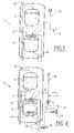
- Station 1 illustrated at figure 1 is a station for supplying a flammable fuel fluid, for example natural gas from a first cryogenic tank 2 storing the flammable fuel in the form of a cryogenic liquid (for example at -140 ° C). More precisely, the first reservoir 2 contains a diphasic liquid / gas mixture.
- Station 1 comprises a second cryogenic tank 3 for storing a non-flammable gas and in particular an inert gas such as nitrogen stored at a temperature of -196 ° C.
- the inert gas is also stored as a cryogenic liquid (two-phase liquid / gas mixture).
- the first 2 and second 3 tanks are preferably double-walled cryogenic tanks with inter-wall void.
- the station 1 comprises a fluid withdrawal circuit 15 for the first tank 3.
- This circuit 15 comprises, for example, a pipe for supplying liquid fuel to a user, for example to fill tanks or tanks of vehicles.
- the withdrawn liquid can be supplied to a vaporization unit to supply a user with gas.
- the station 1 comprises a cooling circuit 4 in heat exchange with the first tank 2 and in particular with the fluid inside the first tank 2.
- the cooling circuit 4 comprises a pipe 4 having an upstream end connected to the second cryogenic tank 3 for withdrawing cryogenic fluid in the second cryogenic tank 3.
- the cooling circuit 4 comprises, downstream, a portion 9 in heat exchange with the interior of the first tank 1 in order to transfer frigories of the fluid from the second cryogenic tank 3 to the first tank 2.
- This heat exchange portion 9 comprises by example a coil, a condenser or any type of appropriate exchanger.
- this exchanger 9 housed inside the first tank 2 is for example located in the upper part of the first tank 2 to cool the gaseous part of the fuel.
- the cooling circuit 4 may comprise a pipe 7 for supplying cooling fluid heated to a user (in gaseous and / or liquid form).
- the downstream portion of the cooling circuit 4 can form a fluid withdrawal circuit 7 of the second tank 3. That is to say that the withdrawal circuit 7 is connected to the cooling circuit 4 and supplied with inert fluid from of the last. That is to say that the withdrawal circuit 7 provides downstream of the fluid initially from the second reservoir 3 and having transited upstream in the cooling circuit (4 and / or 14).
- This withdrawal circuit 7 may comprise a chimney 16 provided with a valve forming a vent in case of determined overpressure.
- the station comprises at least a fuel leakage detector 5 of the first tank 2 and a member 6, 11 controlled opening a portion of the circuit 4, 7 cooling / withdrawal.
- the leak detector 5 is preferably disposed in or adjacent to the station, for example at a distance of between zero and five meters from the tanks 2, 3 or a control cabinet grouping one or more valves of the station.
- the opening member 6 is automatically controlled in response to leak detection by the detector 5 to release fluid from the second cryogenic tank 3 so as to inert a volume within the station.
- the at least one opening member 6 is located on the cooling / extraction circuit downstream of the heat exchange portion with the first reservoir 2, and opens in particular outside the tanks 2, 3. that is to say that the opening member 6 releases in or around the station non-flammable gas from the second tank 3 having exchanged thermally (vaporized in particular) with the first tank 2.
- the leak detector 5 comprises for example at least one of: a fuel sensor (especially a natural gas sensor), a catalytic probe, a chemical sensor, an optical type sensor, or any other suitable system.
- the opening member 6 may comprise at least one of: a valve, a valve, a spray nozzle or any other appropriate device for releasing inert gas in a given zone in response to a fuel leak detection .
- the opening member 6 is spaced from the first reservoir 2 by a distance of between zero and five meters and preferably between zero and two meters, to inert the zone directly adjacent to the first reservoir 2.
- this member 6 opening is located at a distance, to inerter a more distant zone, for example between two and ten meters if the leak is likely to occur there and constitutes a risk area.
- the opening member 6 may comprise an end that opens at least in part. in said cabinet 8 to protect it against fire.
- the envelopes delimiting the storage volumes of the first 2 and second 3 tanks can be housed in a common outer envelope 12 under vacuum. That is, the first 2 and second 3 vacuum insulated tanks containing respective fluids at different temperatures share the same outer shell and the same inter-wall void.
- the figure 2 illustrates a possible variant embodiment of the invention that differs from that of the figure 1 only in that the cooling circuit comprises two separate pipes 4, 14 each provided with an exchanger or coil 9, 10 or condenser housed in the first tank 2.
- the station comprises two members 6, 11 of distinct openings. spaced and fed respectively by the two lines 4, 14.
- the elements identical to those described above are designated by the same reference numerals and are not described a second time.
- the two coils 9, 10 are respectively located in the upper and lower part of the first tank 2 (respectively to exchange with the gaseous and liquid parts of the fluid).
- the two lines 4, 14 are connected to the second reservoir 3 for example by respective upstream ends (alternatively it may be a common end).
- the two organs 6, 11 can thus open in separate or common areas of the station.
- the station 1 makes it possible to effectively use the cooling fluid of the fuel tank to secure the station in the event of fuel leakage.
- the station can be stationary or mobile (mounted on a vehicle or trailer).
Landscapes
- Engineering & Computer Science (AREA)
- Mechanical Engineering (AREA)
- General Engineering & Computer Science (AREA)
- Filling Or Discharging Of Gas Storage Vessels (AREA)
Abstract
Description
- La présente invention concerne une station de fourniture d'un fluide carburant inflammable ainsi qu'un procédé de stockage.
- L'invention concerne plus particulièrement uns station de fourniture d'un fluide carburant inflammable, la station comprenant un premier réservoir cryogénique pour stocker du carburant inflammable sous la forme d'un liquide cryogénique, un second réservoir cryogénique de stockage d'un gaz non inflammable et notamment un gaz inerte stocké sous forme de liquide cryogénique, un circuit de refroidissement en échange thermique avec le premier réservoir, le circuit de refroidissement comprenant une extrémité amont reliée au second réservoir cryogénique pour prélever du fluide cryogénique dans le second réservoir cryogénique en vue de céder des frigories du fluide du second réservoir cryogénique vers le premier réservoir, la station comprenant un circuit de soutirage de fluide du second réservoir.
- Le stockage d'un liquide cryogénique dans un réservoir isolé sous vide est sujet à une remontée de sa pression interne. En effet, en l'absence de soutirage de liquide régulier, les entrées de chaleur par les supports du réservoir, les tuyauteries et l'isolation réchauffent le vide inter-parois. Du liquide se vaporise dans le réservoir et de ce fait la pression va augmenter jusqu'à l'ouverture d'une soupape de sécurité.
- Le dégazage de gaz tels l'azote, l'oxygène et l'argon ne pose pas trop de problème cependant, lorsque le gaz stocké est inflammable (gaz naturel, hydrogène...) un tel dégazage risque de créer un nuage explosif donc une « zone ATEX ».
- Une solution connue consiste à condenser dans le réservoir une partie de la phase gazeuse ou à refroidir le liquide pour éviter sa vaporisation (cf. le document
DE19903214 ). - De plus, en cas de fuite de gaz inflammable, l'installation est également susceptible de provoquer une explosion.
- Les systèmes pour éviter les conséquences négatives de telles fuites sont généralement complexes, coûteux et moyennement efficaces.
- Un but de la présente invention est de pallier tout ou partie des inconvénients de l'art antérieur relevés ci-dessus.
- A cette fin, la station selon l'invention, par ailleurs conforme à la définition générique qu'en donne le préambule ci-dessus, est essentiellement caractérisée en ce qu'elle comprend au moins un détecteur de fuite de carburant du premier réservoir et au moins un organe piloté d'ouverture d'une portion du circuit de soutirage, le au moins un organe d'ouverture étant commandé automatiquement en réponse à une détection de fuite par le au moins détecteur pour relâcher du fluide issu du second réservoir cryogénique de façon à inerter un volume au sein de la station.
- Par ailleurs, des modes de réalisation de l'invention peuvent comporter l'une ou plusieurs des caractéristiques suivantes :
- le détecteur de fuite comprend au moins l'un parmi : un capteur de carburant, une sonde catalytique, un capteur chimique, un capteur de type optique,
- le au moins un organe d'ouverture comprend au moins l'un parmi : un robinet, une vanne, une buse de pulvérisation,
- le au moins un organe d'ouverture est espacé du premier réservoir d'une distance comprise zéro et cinq mètres et de préférence entre zéro et deux mètres,
- la station contient une armoire de commande regroupant des organes fonctionnels de commande de la station et en ce que le au moins organe d'ouverture comporte une extrémité qui débouche au moins en partie dans ladite armoire,
- le circuit de refroidissement comprend au moins un échangeur ou serpentin logé à l'intérieur du premier réservoir,
- le circuit de soutirage est relié au circuit de refroidissement et alimenté en fluide issu de ce dernier,
- la station comprend deux organes d'ouvertures distincts espacés,
- le circuit de refroidissement comprend deux conduites distinctes reliées par une extrémité amont au second réservoir et munies chacune d'un échangeur ou serpentin ou condenseur logé dans le premier réservoir, les deux serpentins étant situés respectivement dans les partie supérieure et inférieure du premier réservoir,
- la station comprend deux organes d'ouvertures situés respectivement sur deux portions distincte du circuit de soutirage reliées respectivement au deux conduites distinctes du circuit de refroidissement munies des échangeurs ou serpentins,
- les premier et second réservoirs sont des réservoirs cryogéniques à double parois avec vide inter-parois,
- les premier et second réservoirs sont logés dans une enveloppe extérieure commune sous vide,
- L'invention concerne également un procédé de stockage d'un fluide carburant inflammable dans une station de remplissage comprenant un premier réservoir cryogénique stockant du carburant inflammable sous la forme d'un liquide cryogénique, un second réservoir cryogénique stockant un gaz inerte à une température inférieure à la température du fluide contenu dans le premier réservoir, la station comprenant un circuit de refroidissement en échange thermique avec le premier réservoir, le circuit de refroidissement comprenant une extrémité amont reliée au second réservoir cryogénique, le procédé comprenant une étape de soutirage de fluide cryogénique du second réservoir cryogénique, une étape d'échange thermique entre ce fluide soutiré et le fluide contenu dans le second réservoir cryogénique pour réduire ou supprimer la vaporisation du fluide dans le premier réservoir, le procédé comportant une étape de détection d'une éventuelle fuite de fluide du premier réservoir et, en cas de détection d'une telle fuite, une étape de libération de fluide issu du second réservoir dans l'atmosphère au sein de la station de façon adjacente au premier réservoir pour empêcher une inflammation par inertage.
- Selon d'autres particularités possibles :
- le fluide contenu dans le premier réservoir comprend au moins un parmi : du gaz naturel, du méthane, de l'hydrogène et en ce que le fluide contenu dans le second réservoir comprend au moins un parmi : de l'azote, de l'argon,
- le fluide relâché en cas de détection d'une fuite de fluide du premier réservoir provient du fluide ayant échangé thermiquement avec le fluide du second réservoir cryogénique.
- L'invention peut concerner également tout dispositif ou procédé alternatif comprenant toute combinaison des caractéristiques ci-dessus ou ci-dessous.
- D'autres particularités et avantages apparaîtront à la lecture de la description ci-après, faite en référence aux figures dans lesquelles :
- la
figure 1 représente une vue en coupe, schématique et partielle, illustrant un premier exemple de réalisation d'une station de fourniture de carburant selon l'invention, - la
figure 2 représente une vue en coupe, schématique et partielle, illustrant un second exemple de réalisation d'une station de fourniture de carburant selon l'invention. - La station 1 illustrée à la
figure 1 est une station de fourniture d'un fluide carburant inflammable, par exemple du gaz naturel à partir d'un premier réservoir 2 cryogénique stockant le carburant inflammable sous la forme d'un liquide cryogénique (par exemple à -140°C). Plus précisément, le premier réservoir 2 contient un mélange diphasique liquide/gaz. - La station 1 comprend un second réservoir 3 cryogénique de stockage d'un gaz non inflammable et notamment un gaz inerte tel que de l'azote stocké à une température de -196°C.
- Le gaz inerte est également stocké sous forme de liquide cryogénique (mélange diphasique liquide/gaz).
- Les premier 2 et second 3 réservoirs sont de préférence des réservoirs cryogéniques à double parois avec vide inter-parois.
- La station 1 comprend un circuit 15 de soutirage de fluide du premier réservoir 3. Ce circuit 15 comprend par exemple une conduite de fourniture de carburant liquide vers un utilisateur, par exemple pour remplir des capacités ou des réservoirs de véhicules. Alternativement ou en combinaison, le liquide soutiré peut être fourni à une unité de vaporisation pour alimenter un utilisateur en gaz.
- La station 1 comprend un circuit 4 de refroidissement en échange thermique avec le premier réservoir 2 et notamment avec le fluide à l'intérieur du premier 2 réservoir. Le circuit 4 de refroidissement comprend une conduite 4 ayant une extrémité amont reliée au second réservoir 3 cryogénique pour prélever du fluide cryogénique dans le second réservoir 3 cryogénique. Le circuit 4 de refroidissement comprend en aval une portion 9 en échange thermique avec l'intérieur du premier réservoir 1 en vue de céder des frigories du fluide du second réservoir 3 cryogénique vers le premier réservoir 2. Cette portion 9 d'échange thermique comprend par exemple un serpentin, un condenseur ou tout type d'échangeur approprié.
- Sans que ce soit limitatif pour autant, cet échangeur 9 logé à l'intérieur du premier réservoir 2 est par exemple situé en partie supérieure du premier réservoir 2 pour refroidir la partie gazeuse du carburant. En aval de cet échangeur 9, le circuit 4 de refroidissement peut comporter une conduite 7 de fourniture de fluide de refroidissement réchauffé à un utilisateur (sous forme gazeuse et/ou liquide). Ainsi, la partie aval du circuit 4 de refroidissement peut former un circuit 7 de soutirage de fluide du second réservoir 3. C'est-à-dire que le circuit 7 de soutirage est relié au circuit 4 de refroidissement et alimenté en fluide inerte issu de ce dernier. C'est-à-dire que le circuit de soutirage 7 fournit en aval du fluide issu initialement du second réservoir 3 et ayant transité en amont dans le circuit de refroidissement (4 et/ou 14).
- Ce circuit 7 de soutirage peut comporter une cheminée 16 munie d'un clapet formant un évent en cas de surpression déterminée.
- Selon une particularité avantageuse, la station comprend au moins un détecteur 5 de fuite de carburant du premier réservoir 2 et un organe 6, 11 piloté d'ouverture d'une portion du circuit 4, 7 de refroidissement/soutirage.
- Le détecteur 5 de fuite est disposé de préférence dans ou de façon adjacente à la station, par exemple à une distance comprise entre zéro et cinq mètres par rapport aux réservoirs 2, 3 ou une armoire de commande regroupant une ou des vannes de la station.
- L'organe 6 d'ouverture est commandé automatiquement en réponse à une détection de fuite par le détecteur 5 pour relâcher du fluide issu du second réservoir 3 cryogénique de façon à inerter un volume au sein de la station.
- Le au moins un organe 6 d'ouverture est situé sur le circuit de refroidissement/soutirage en aval de la portion en échange thermique avec le premier réservoir 2, et débouche notamment à l'extérieur des réservoirs 2, 3. C'est-à-dire que l'organe 6 d'ouverture relâche dans ou autour de la station du gaz non inflammable provenant du second réservoir 3 ayant échangé thermiquement (vaporisé notamment) avec le premier réservoir 2.
- Le détecteur 5 de fuite comprend par exemple au moins l'un parmi : un capteur de carburant (notamment un capteur de gaz naturel), une sonde catalytique, un capteur chimique, un capteur de type optique, ou tout autre système approprié.
- L'organe 6 d'ouverture peut comprend au moins l'un parmi : un robinet, une vanne, une buse de pulvérisation ou tout autre dispositif approprié permettant de libérer du gaz inerte dans une zone déterminée en réponse à une détection de fuite de carburant.
- Par exemple, l'organe 6 d'ouverture est espacé du premier réservoir 2 d'une distance comprise zéro et cinq mètres et de préférence entre zéro et deux mètres, pour inerter la zone directement adjacente au premier réservoir 2. En variante, cet organe 6 d'ouverture est situé à distance, pour inerter une zone plus éloignée, par exemple entre deux et dix mètre si la fuite est susceptible de s'y produire et constitue une zone à risque.
- Dans le cas où la station comprend une armoire 8 de commande regroupant des organes fonctionnels de commande de la station (vannes, électronique de commande, afficheurs...) l'organe 6 d'ouverture peut comporter une extrémité qui débouche au moins en partie dans ladite armoire 8 en vue de la protéger contre l'incendie.
- Comme illustré à la
figure 1 , de façon avantageuse mais non impérative, les enveloppes délimitant les volumes de stockage des premier 2 et second 3 réservoirs peuvent être logées dans une enveloppe 12 extérieure commune sous vide. C'est-à-dire que les premier 2 et second 3 réservoirs isolés sous vide contenant des fluides respectifs à des températures distinctes partagent la même enveloppe extérieure et le même vide inter-parois. - La
figure 2 illustre une variante possible de réalisation de l'invention qui se distingue de celle de lafigure 1 uniquement en ce que le circuit de refroidissement comprend deux conduites 4, 14 distinctes munies chacune d'un échangeur ou serpentin 9, 10 ou condenseur logé dans le premier réservoir 2. De plus, la station comprend deux organes 6, 11 d'ouvertures distincts espacés et alimentés respectivement par les deux conduites 4, 14. Les éléments identiques à ceux décrits précédemment sont désignés par les mêmes références numériques et ne sont pas décrits une seconde fois. - Comme illustré, de préférence les deux serpentins 9, 10 sont situés respectivement dans les partie supérieure et inférieure du premier réservoir 2 (respectivement pour échanger avec les parties gazeuse et liquide du fluide).
- Les deux conduites 4, 14 sont reliées au second réservoir 3 par exemple par des extrémités amont respectives (en variante cela peut être une extrémité commune).
- Les deux organes 6, 11 peuvent ainsi déboucher dans des zones distinctes ou communes de la station.
- On conçoit donc aisément que tout en étant de structure simple et peu coûteuse, la station 1 permet d'utiliser efficacement le fluide de refroidissement du réservoir de carburant pour sécuriser la station en cas de fuite de carburant. La station peut être fixe ou mobile (montée sur un véhicule ou une remorque).
Claims (13)
- Station de fourniture d'un fluide carburant inflammable, la station (1) comprenant un premier réservoir (2) cryogénique pour stocker du carburant inflammable sous la forme d'un liquide cryogénique, un second réservoir (3) cryogénique de stockage d'un gaz non inflammable et notamment un gaz inerte stocké sous forme de liquide cryogénique, un circuit (4, 14) de refroidissement en échange thermique avec le premier réservoir (2), le circuit (4, 14) de refroidissement comprenant au moins une extrémité amont reliée au second réservoir (3) cryogénique pour prélever du fluide cryogénique dans le second réservoir (3) cryogénique en vue de céder des frigories du fluide du second réservoir (3) cryogénique vers le premier réservoir (2), la station comprenant un circuit (4, 14, 7) de soutirage de fluide du second réservoir (3), caractérisée en ce que la station comprend au moins un détecteur (5) de fuite de carburant du premier réservoir (2) et au moins un organe (6, 11) piloté d'ouverture d'une portion du circuit (4, 14, 7) de soutirage, le au moins un organe (6) d'ouverture étant commandé automatiquement en réponse à une détection de fuite par le au moins détecteur (5) pour relâcher du fluide issu du second réservoir (3) cryogénique de façon à inerter un volume au sein de la station et en ce que le circuit (7) de soutirage de fluide du second réservoir (3) est relié au circuit (4, 14) de refroidissement et alimenté en fluide issu de ce dernier.
- Station selon la revendication 1, caractérisée en ce que le détecteur (5) de fuite comprend au moins l'un parmi : un capteur de carburant, une sonde catalytique, un capteur chimique, un capteur de type optique.
- Station selon la revendication 1 ou 2, caractérisée en ce que le au moins un organe (6, 11) d'ouverture comprend au moins l'un parmi: un robinet, une vanne, une buse de pulvérisation.
- Station selon l'une quelconque des revendications 1 à 3, caractérisée en ce que le au moins un organe (6, 11) d'ouverture est espacé du premier réservoir (2) d'une distance comprise zéro et cinq mètres et de préférence entre zéro et deux mètres.
- Station selon l'une quelconque des revendications 1 à 4, caractérisée en ce qu'elle contient une armoire (8) de commande regroupant des organes fonctionnels de commande de la station et en ce que le au moins organe (6, 11) d'ouverture comporte une extrémité qui débouche au moins en partie dans ladite armoire (8).
- Station selon l'une quelconque des revendications 1 à 5, caractérisée en ce que le circuit (4, 14) de refroidissement comprend au moins un échangeur ou serpentin (9, 10) logé à l'intérieur du premier réservoir (2).
- Station selon l'une quelconque des revendications 1 à 6, caractérisée en ce qu'elle comprend deux organes (6, 11) d'ouvertures distincts espacés.
- Station selon l'une quelconque des revendications 1 à 7, caractérisée en ce que le circuit de refroidissement comprend deux conduites (4, 14) distinctes reliées par une extrémité amont au second réservoir (3) et munies chacune d'un échangeur ou serpentin (9, 10) ou condenseur logé dans le premier réservoir (2), les deux serpentins (9, 10) étant situés respectivement dans les partie supérieure et inférieure du premier réservoir (2).
- Station selon la revendication 8, caractérisée en ce qu'elle comprend deux organes (6, 11) d'ouvertures situés respectivement sur deux portions distincte du circuit (7) de soutirage reliées respectivement au deux conduites (4, 14) distinctes du circuit de refroidissement munies des échangeurs ou serpentins (9, 10).
- Station selon l'une quelconque des revendications 1 à 9, caractérisée en ce que les premier (2) et second (3) réservoirs sont des réservoirs cryogéniques à double parois avec vide inter-parois.
- Station selon la revendication 10, caractérisée en ce que les premier (2) et second (3) réservoirs sont logés dans une enveloppe (12) extérieure commune sous vide.
- Procédé de stockage d'un fluide carburant inflammable dans une station de remplissage comprenant un premier réservoir (2) cryogénique stockant du carburant inflammable sous la forme d'un liquide cryogénique, un second réservoir (3) cryogénique stockant un gaz inerte à une température inférieure à la température du fluide contenu dans le premier réservoir (2), la station comprenant un circuit (4, 14) de refroidissement en échange thermique avec le premier réservoir (2), le circuit (4, 14) de refroidissement comprenant une extrémité amont reliée au second réservoir (3) cryogénique, le procédé comprenant une étape de soutirage de fluide cryogénique du second réservoir (3) cryogénique, une étape d'échange thermique entre ce fluide soutiré et le fluide contenu dans le second réservoir (3) cryogénique pour réduire ou supprimer la vaporisation du fluide dans le premier réservoir (2), le procédé étant caractérisé en ce qu'il comporte une étape de détection d'une éventuelle fuite de fluide du premier réservoir (2) et, en cas de détection d'une telle fuite, une étape de libération de fluide issu du second réservoir (3) dans l'atmosphère au sein de la station de façon adjacente au premier réservoir (2) pour empêcher une inflammation par inertage et en ce que le circuit (7) de soutirage de fluide du second réservoir (3) est relié au circuit (4, 14) de refroidissement et alimenté en fluide issu de ce dernier.
- Procédé selon la revendication 12, caractérisé en ce que le fluide contenu dans le premier réservoir (2) comprend au moins un parmi : du gaz naturel, du méthane, de l'hydrogène et en ce que le fluide contenu dans le second réservoir (3) comprend au moins un parmi : de l'azote, de l'argon.
Priority Applications (1)
| Application Number | Priority Date | Filing Date | Title |
|---|---|---|---|
| PL14189611T PL2910842T3 (pl) | 2014-01-21 | 2014-10-21 | Stacja i sposób dostarczania łatwopalnego paliwa płynnego |
Applications Claiming Priority (1)
| Application Number | Priority Date | Filing Date | Title |
|---|---|---|---|
| FR1450456A FR3016682B1 (fr) | 2014-01-21 | 2014-01-21 | Station et procede de fourniture d'un fluide carburant inflammable |
Publications (3)
| Publication Number | Publication Date |
|---|---|
| EP2910842A2 true EP2910842A2 (fr) | 2015-08-26 |
| EP2910842A3 EP2910842A3 (fr) | 2015-11-04 |
| EP2910842B1 EP2910842B1 (fr) | 2019-02-20 |
Family
ID=50729615
Family Applications (1)
| Application Number | Title | Priority Date | Filing Date |
|---|---|---|---|
| EP14189611.8A Active EP2910842B1 (fr) | 2014-01-21 | 2014-10-21 | Station et procédé de fourniture d'un fluide carburant inflammable |
Country Status (5)
| Country | Link |
|---|---|
| US (1) | US20150204485A1 (fr) |
| EP (1) | EP2910842B1 (fr) |
| DK (1) | DK2910842T3 (fr) |
| FR (1) | FR3016682B1 (fr) |
| PL (1) | PL2910842T3 (fr) |
Families Citing this family (4)
| Publication number | Priority date | Publication date | Assignee | Title |
|---|---|---|---|---|
| FR3067092B1 (fr) * | 2017-05-31 | 2020-08-14 | L'air Liquide Sa Pour L'etude Et L'exploitation Des Procedes Georges Claude | Station et procede de remplissage de reservoir(s) de gaz sous pression |
| JP6441428B1 (ja) * | 2017-09-11 | 2018-12-19 | 株式会社東芝 | 液体貯留システム及び液体貯留システムにおける不燃性ガスの供給方法 |
| WO2019210197A1 (fr) * | 2018-04-26 | 2019-10-31 | Chart Inc. | Système de distribution de fluide cryogénique comportant un réservoir de réfrigération |
| CN116552699B (zh) * | 2023-06-02 | 2024-01-16 | 江苏新时代造船有限公司 | 一种双燃料船舶自充压lng液罐 |
Citations (1)
| Publication number | Priority date | Publication date | Assignee | Title |
|---|---|---|---|---|
| DE19903214A1 (de) | 1999-01-27 | 2000-08-03 | Linde Ag | Verfahren zur Betankung von Flüssigkeitstanks mit unterkühlter Flüssigkeit |
Family Cites Families (8)
| Publication number | Priority date | Publication date | Assignee | Title |
|---|---|---|---|---|
| US3374639A (en) * | 1966-10-25 | 1968-03-26 | Mcmullen John J | Leak detection and pressure relief system for insulated liquefied gas storage tanks |
| US3838576A (en) * | 1971-02-12 | 1974-10-01 | Parker Hannifin Corp | Integrated emergency oxygen and fuel tank inerting system |
| US4292062A (en) * | 1980-03-20 | 1981-09-29 | Dinulescu Horia A | Cryogenic fuel tank |
| FR2794843B1 (fr) * | 1999-06-08 | 2001-08-03 | Air Liquide | Dispositif de reglage de pression pour un reservoir cryogenique et installation de fourniture de fluide correspondante |
| US7287558B2 (en) * | 2003-07-03 | 2007-10-30 | Arizona Public Service Company | Hydrogen handling or dispensing system |
| DE102011103748A1 (de) * | 2011-05-31 | 2012-12-06 | Ipsen International Gmbh | Verfahren zur Steuerung von Vakuumpumpen in einer Industrieofenanlage |
| GB201211078D0 (en) * | 2012-06-21 | 2012-08-01 | Linde Ag | Storage vessel |
| WO2014086413A1 (fr) * | 2012-12-05 | 2014-06-12 | Blue Wave Co S.A. | Système intégré et amélioré pour le transport maritime de gaz naturel comprimé dans des cuves, comprenant de multiples étapes de traitement pour abaisser la température combinant le refroidissement et la réfrigération |
-
2014
- 2014-01-21 FR FR1450456A patent/FR3016682B1/fr not_active Expired - Fee Related
- 2014-10-21 PL PL14189611T patent/PL2910842T3/pl unknown
- 2014-10-21 EP EP14189611.8A patent/EP2910842B1/fr active Active
- 2014-10-21 DK DK14189611.8T patent/DK2910842T3/en active
-
2015
- 2015-01-21 US US14/601,470 patent/US20150204485A1/en not_active Abandoned
Patent Citations (1)
| Publication number | Priority date | Publication date | Assignee | Title |
|---|---|---|---|---|
| DE19903214A1 (de) | 1999-01-27 | 2000-08-03 | Linde Ag | Verfahren zur Betankung von Flüssigkeitstanks mit unterkühlter Flüssigkeit |
Also Published As
| Publication number | Publication date |
|---|---|
| DK2910842T3 (en) | 2019-04-08 |
| US20150204485A1 (en) | 2015-07-23 |
| EP2910842A3 (fr) | 2015-11-04 |
| EP2910842B1 (fr) | 2019-02-20 |
| PL2910842T3 (pl) | 2019-08-30 |
| FR3016682A1 (fr) | 2015-07-24 |
| FR3016682B1 (fr) | 2017-01-27 |
Similar Documents
| Publication | Publication Date | Title |
|---|---|---|
| EP2896872B1 (fr) | Station et procédé de fourniture d'un fluide carburant inflammable cryogénique | |
| EP3942220B1 (fr) | Dispositif et procédé de stockage et de fourniture de carburant fluide | |
| EP2910842B1 (fr) | Station et procédé de fourniture d'un fluide carburant inflammable | |
| US7546744B2 (en) | Storage tank for a cryogenic liquid and method of re-filling same | |
| EP4075048B1 (fr) | Dispositif de stockage et de fourniture de fluide, véhicule et procédé comportant un tel dispositif | |
| EP3710741B1 (fr) | Dispositif d'inertage d'une cuve de stockage de gaz liquefie pour un navire de transport de ce gaz | |
| EP3891429B1 (fr) | Réservoir de stockage de fluide cryogénique | |
| EP3084286B1 (fr) | Transfert de gaz naturel liquéfié | |
| FR2976045A1 (fr) | Reservoir de fluide sous pression | |
| WO2013190254A2 (fr) | Récipient de stockage | |
| EP4334634B1 (fr) | Dispositif de stockage et de fourniture de fluide cryogénique, véhicule et procédé correspondant | |
| EP3645934B1 (fr) | Station et procédé de remplissage de réservoirs de gaz sous pression | |
| WO2023151845A1 (fr) | Dispositif et procédé de stockage et de fourniture de fluide | |
| FR3016683A1 (fr) | Station et procede de fourniture d'un fluide carburant inflammable | |
| WO2021148297A1 (fr) | Réservoir cryogénique mobile et procédé d'approvisionnement | |
| EP1952054B1 (fr) | Dispositif et procede de protection d'un reservoir cryogenique et reservoir comportant un tel dispositif | |
| CN204901318U (zh) | 一种焊接绝热气瓶 | |
| CN111237629B (zh) | 船用天然气储罐 | |
| EP4095429B1 (fr) | Récipient cryogénique | |
| FR3161667A1 (fr) | Dispositif de protection d’un réservoir à hydrogène d’un aéronef | |
| WO2018015641A1 (fr) | Purge anticipée d'un réservoir cryogénique | |
| FR3060550A1 (fr) | Station et procede de remplissage de reservoir(s) |
Legal Events
| Date | Code | Title | Description |
|---|---|---|---|
| PUAI | Public reference made under article 153(3) epc to a published international application that has entered the european phase |
Free format text: ORIGINAL CODE: 0009012 |
|
| AK | Designated contracting states |
Kind code of ref document: A2 Designated state(s): AL AT BE BG CH CY CZ DE DK EE ES FI FR GB GR HR HU IE IS IT LI LT LU LV MC MK MT NL NO PL PT RO RS SE SI SK SM TR |
|
| AX | Request for extension of the european patent |
Extension state: BA ME |
|
| PUAL | Search report despatched |
Free format text: ORIGINAL CODE: 0009013 |
|
| AK | Designated contracting states |
Kind code of ref document: A3 Designated state(s): AL AT BE BG CH CY CZ DE DK EE ES FI FR GB GR HR HU IE IS IT LI LT LU LV MC MK MT NL NO PL PT RO RS SE SI SK SM TR |
|
| AX | Request for extension of the european patent |
Extension state: BA ME |
|
| RIC1 | Information provided on ipc code assigned before grant |
Ipc: F17C 13/12 20060101ALI20150928BHEP Ipc: F17C 5/00 20060101ALI20150928BHEP Ipc: F17C 13/02 20060101AFI20150928BHEP |
|
| 17P | Request for examination filed |
Effective date: 20160504 |
|
| RBV | Designated contracting states (corrected) |
Designated state(s): AL AT BE BG CH CY CZ DE DK EE ES FI FR GB GR HR HU IE IS IT LI LT LU LV MC MK MT NL NO PL PT RO RS SE SI SK SM TR |
|
| GRAP | Despatch of communication of intention to grant a patent |
Free format text: ORIGINAL CODE: EPIDOSNIGR1 |
|
| STAA | Information on the status of an ep patent application or granted ep patent |
Free format text: STATUS: GRANT OF PATENT IS INTENDED |
|
| INTG | Intention to grant announced |
Effective date: 20180918 |
|
| GRAS | Grant fee paid |
Free format text: ORIGINAL CODE: EPIDOSNIGR3 |
|
| GRAA | (expected) grant |
Free format text: ORIGINAL CODE: 0009210 |
|
| STAA | Information on the status of an ep patent application or granted ep patent |
Free format text: STATUS: THE PATENT HAS BEEN GRANTED |
|
| AK | Designated contracting states |
Kind code of ref document: B1 Designated state(s): AL AT BE BG CH CY CZ DE DK EE ES FI FR GB GR HR HU IE IS IT LI LT LU LV MC MK MT NL NO PL PT RO RS SE SI SK SM TR |
|
| REG | Reference to a national code |
Ref country code: GB Ref legal event code: FG4D Free format text: NOT ENGLISH |
|
| REG | Reference to a national code |
Ref country code: CH Ref legal event code: EP |
|
| REG | Reference to a national code |
Ref country code: DE Ref legal event code: R096 Ref document number: 602014041176 Country of ref document: DE |
|
| REG | Reference to a national code |
Ref country code: AT Ref legal event code: REF Ref document number: 1098655 Country of ref document: AT Kind code of ref document: T Effective date: 20190315 |
|
| REG | Reference to a national code |
Ref country code: IE Ref legal event code: FG4D Free format text: LANGUAGE OF EP DOCUMENT: FRENCH |
|
| REG | Reference to a national code |
Ref country code: DK Ref legal event code: T3 Effective date: 20190401 |
|
| REG | Reference to a national code |
Ref country code: NL Ref legal event code: FP |
|
| REG | Reference to a national code |
Ref country code: LT Ref legal event code: MG4D |
|
| PG25 | Lapsed in a contracting state [announced via postgrant information from national office to epo] |
Ref country code: LT Free format text: LAPSE BECAUSE OF FAILURE TO SUBMIT A TRANSLATION OF THE DESCRIPTION OR TO PAY THE FEE WITHIN THE PRESCRIBED TIME-LIMIT Effective date: 20190220 Ref country code: NO Free format text: LAPSE BECAUSE OF FAILURE TO SUBMIT A TRANSLATION OF THE DESCRIPTION OR TO PAY THE FEE WITHIN THE PRESCRIBED TIME-LIMIT Effective date: 20190520 Ref country code: SE Free format text: LAPSE BECAUSE OF FAILURE TO SUBMIT A TRANSLATION OF THE DESCRIPTION OR TO PAY THE FEE WITHIN THE PRESCRIBED TIME-LIMIT Effective date: 20190220 Ref country code: PT Free format text: LAPSE BECAUSE OF FAILURE TO SUBMIT A TRANSLATION OF THE DESCRIPTION OR TO PAY THE FEE WITHIN THE PRESCRIBED TIME-LIMIT Effective date: 20190620 |
|
| PG25 | Lapsed in a contracting state [announced via postgrant information from national office to epo] |
Ref country code: IS Free format text: LAPSE BECAUSE OF FAILURE TO SUBMIT A TRANSLATION OF THE DESCRIPTION OR TO PAY THE FEE WITHIN THE PRESCRIBED TIME-LIMIT Effective date: 20190620 Ref country code: LV Free format text: LAPSE BECAUSE OF FAILURE TO SUBMIT A TRANSLATION OF THE DESCRIPTION OR TO PAY THE FEE WITHIN THE PRESCRIBED TIME-LIMIT Effective date: 20190220 Ref country code: GR Free format text: LAPSE BECAUSE OF FAILURE TO SUBMIT A TRANSLATION OF THE DESCRIPTION OR TO PAY THE FEE WITHIN THE PRESCRIBED TIME-LIMIT Effective date: 20190521 Ref country code: HR Free format text: LAPSE BECAUSE OF FAILURE TO SUBMIT A TRANSLATION OF THE DESCRIPTION OR TO PAY THE FEE WITHIN THE PRESCRIBED TIME-LIMIT Effective date: 20190220 Ref country code: RS Free format text: LAPSE BECAUSE OF FAILURE TO SUBMIT A TRANSLATION OF THE DESCRIPTION OR TO PAY THE FEE WITHIN THE PRESCRIBED TIME-LIMIT Effective date: 20190220 Ref country code: BG Free format text: LAPSE BECAUSE OF FAILURE TO SUBMIT A TRANSLATION OF THE DESCRIPTION OR TO PAY THE FEE WITHIN THE PRESCRIBED TIME-LIMIT Effective date: 20190520 |
|
| REG | Reference to a national code |
Ref country code: AT Ref legal event code: MK05 Ref document number: 1098655 Country of ref document: AT Kind code of ref document: T Effective date: 20190220 |
|
| PG25 | Lapsed in a contracting state [announced via postgrant information from national office to epo] |
Ref country code: AL Free format text: LAPSE BECAUSE OF FAILURE TO SUBMIT A TRANSLATION OF THE DESCRIPTION OR TO PAY THE FEE WITHIN THE PRESCRIBED TIME-LIMIT Effective date: 20190220 Ref country code: ES Free format text: LAPSE BECAUSE OF FAILURE TO SUBMIT A TRANSLATION OF THE DESCRIPTION OR TO PAY THE FEE WITHIN THE PRESCRIBED TIME-LIMIT Effective date: 20190220 Ref country code: RO Free format text: LAPSE BECAUSE OF FAILURE TO SUBMIT A TRANSLATION OF THE DESCRIPTION OR TO PAY THE FEE WITHIN THE PRESCRIBED TIME-LIMIT Effective date: 20190220 Ref country code: EE Free format text: LAPSE BECAUSE OF FAILURE TO SUBMIT A TRANSLATION OF THE DESCRIPTION OR TO PAY THE FEE WITHIN THE PRESCRIBED TIME-LIMIT Effective date: 20190220 Ref country code: SK Free format text: LAPSE BECAUSE OF FAILURE TO SUBMIT A TRANSLATION OF THE DESCRIPTION OR TO PAY THE FEE WITHIN THE PRESCRIBED TIME-LIMIT Effective date: 20190220 |
|
| REG | Reference to a national code |
Ref country code: DE Ref legal event code: R097 Ref document number: 602014041176 Country of ref document: DE |
|
| PG25 | Lapsed in a contracting state [announced via postgrant information from national office to epo] |
Ref country code: SM Free format text: LAPSE BECAUSE OF FAILURE TO SUBMIT A TRANSLATION OF THE DESCRIPTION OR TO PAY THE FEE WITHIN THE PRESCRIBED TIME-LIMIT Effective date: 20190220 |
|
| PLBE | No opposition filed within time limit |
Free format text: ORIGINAL CODE: 0009261 |
|
| STAA | Information on the status of an ep patent application or granted ep patent |
Free format text: STATUS: NO OPPOSITION FILED WITHIN TIME LIMIT |
|
| PG25 | Lapsed in a contracting state [announced via postgrant information from national office to epo] |
Ref country code: AT Free format text: LAPSE BECAUSE OF FAILURE TO SUBMIT A TRANSLATION OF THE DESCRIPTION OR TO PAY THE FEE WITHIN THE PRESCRIBED TIME-LIMIT Effective date: 20190220 |
|
| 26N | No opposition filed |
Effective date: 20191121 |
|
| PG25 | Lapsed in a contracting state [announced via postgrant information from national office to epo] |
Ref country code: SI Free format text: LAPSE BECAUSE OF FAILURE TO SUBMIT A TRANSLATION OF THE DESCRIPTION OR TO PAY THE FEE WITHIN THE PRESCRIBED TIME-LIMIT Effective date: 20190220 |
|
| PG25 | Lapsed in a contracting state [announced via postgrant information from national office to epo] |
Ref country code: TR Free format text: LAPSE BECAUSE OF FAILURE TO SUBMIT A TRANSLATION OF THE DESCRIPTION OR TO PAY THE FEE WITHIN THE PRESCRIBED TIME-LIMIT Effective date: 20190220 |
|
| PG25 | Lapsed in a contracting state [announced via postgrant information from national office to epo] |
Ref country code: MC Free format text: LAPSE BECAUSE OF FAILURE TO SUBMIT A TRANSLATION OF THE DESCRIPTION OR TO PAY THE FEE WITHIN THE PRESCRIBED TIME-LIMIT Effective date: 20190220 |
|
| REG | Reference to a national code |
Ref country code: CH Ref legal event code: PL |
|
| PG25 | Lapsed in a contracting state [announced via postgrant information from national office to epo] |
Ref country code: LI Free format text: LAPSE BECAUSE OF NON-PAYMENT OF DUE FEES Effective date: 20191031 Ref country code: LU Free format text: LAPSE BECAUSE OF NON-PAYMENT OF DUE FEES Effective date: 20191021 Ref country code: CH Free format text: LAPSE BECAUSE OF NON-PAYMENT OF DUE FEES Effective date: 20191031 |
|
| PG25 | Lapsed in a contracting state [announced via postgrant information from national office to epo] |
Ref country code: IE Free format text: LAPSE BECAUSE OF NON-PAYMENT OF DUE FEES Effective date: 20191021 |
|
| PG25 | Lapsed in a contracting state [announced via postgrant information from national office to epo] |
Ref country code: CY Free format text: LAPSE BECAUSE OF FAILURE TO SUBMIT A TRANSLATION OF THE DESCRIPTION OR TO PAY THE FEE WITHIN THE PRESCRIBED TIME-LIMIT Effective date: 20190220 |
|
| PG25 | Lapsed in a contracting state [announced via postgrant information from national office to epo] |
Ref country code: HU Free format text: LAPSE BECAUSE OF FAILURE TO SUBMIT A TRANSLATION OF THE DESCRIPTION OR TO PAY THE FEE WITHIN THE PRESCRIBED TIME-LIMIT; INVALID AB INITIO Effective date: 20141021 Ref country code: MT Free format text: LAPSE BECAUSE OF FAILURE TO SUBMIT A TRANSLATION OF THE DESCRIPTION OR TO PAY THE FEE WITHIN THE PRESCRIBED TIME-LIMIT Effective date: 20190220 |
|
| PG25 | Lapsed in a contracting state [announced via postgrant information from national office to epo] |
Ref country code: MK Free format text: LAPSE BECAUSE OF FAILURE TO SUBMIT A TRANSLATION OF THE DESCRIPTION OR TO PAY THE FEE WITHIN THE PRESCRIBED TIME-LIMIT Effective date: 20190220 |
|
| PGFP | Annual fee paid to national office [announced via postgrant information from national office to epo] |
Ref country code: NL Payment date: 20231019 Year of fee payment: 10 |
|
| PGFP | Annual fee paid to national office [announced via postgrant information from national office to epo] |
Ref country code: GB Payment date: 20231020 Year of fee payment: 10 |
|
| PGFP | Annual fee paid to national office [announced via postgrant information from national office to epo] |
Ref country code: IT Payment date: 20231020 Year of fee payment: 10 Ref country code: FI Payment date: 20231020 Year of fee payment: 10 Ref country code: DK Payment date: 20231024 Year of fee payment: 10 |
|
| PGFP | Annual fee paid to national office [announced via postgrant information from national office to epo] |
Ref country code: PL Payment date: 20231017 Year of fee payment: 10 Ref country code: BE Payment date: 20231019 Year of fee payment: 10 |
|
| REG | Reference to a national code |
Ref country code: DK Ref legal event code: EBP Effective date: 20241031 |
|
| REG | Reference to a national code |
Ref country code: NL Ref legal event code: MM Effective date: 20241101 |
|
| GBPC | Gb: european patent ceased through non-payment of renewal fee |
Effective date: 20241021 |
|
| PG25 | Lapsed in a contracting state [announced via postgrant information from national office to epo] |
Ref country code: FI Free format text: LAPSE BECAUSE OF NON-PAYMENT OF DUE FEES Effective date: 20241021 |
|
| PG25 | Lapsed in a contracting state [announced via postgrant information from national office to epo] |
Ref country code: GB Free format text: LAPSE BECAUSE OF NON-PAYMENT OF DUE FEES Effective date: 20241021 |
|
| PG25 | Lapsed in a contracting state [announced via postgrant information from national office to epo] |
Ref country code: BE Free format text: LAPSE BECAUSE OF NON-PAYMENT OF DUE FEES Effective date: 20241031 Ref country code: NL Free format text: LAPSE BECAUSE OF NON-PAYMENT OF DUE FEES Effective date: 20241101 |
|
| REG | Reference to a national code |
Ref country code: BE Ref legal event code: MM Effective date: 20241031 |
|
| PG25 | Lapsed in a contracting state [announced via postgrant information from national office to epo] |
Ref country code: DK Free format text: LAPSE BECAUSE OF NON-PAYMENT OF DUE FEES Effective date: 20241031 |
|
| PG25 | Lapsed in a contracting state [announced via postgrant information from national office to epo] |
Ref country code: IT Free format text: LAPSE BECAUSE OF NON-PAYMENT OF DUE FEES Effective date: 20241021 |
|
| PGFP | Annual fee paid to national office [announced via postgrant information from national office to epo] |
Ref country code: DE Payment date: 20251021 Year of fee payment: 12 |
|
| PGFP | Annual fee paid to national office [announced via postgrant information from national office to epo] |
Ref country code: FR Payment date: 20251030 Year of fee payment: 12 |
|
| PGFP | Annual fee paid to national office [announced via postgrant information from national office to epo] |
Ref country code: CZ Payment date: 20251015 Year of fee payment: 12 |