EP2910852B1 - Energieeffiziente Reflektorlampe mit hoher Intensität - Google Patents
Energieeffiziente Reflektorlampe mit hoher Intensität Download PDFInfo
- Publication number
- EP2910852B1 EP2910852B1 EP14156253.8A EP14156253A EP2910852B1 EP 2910852 B1 EP2910852 B1 EP 2910852B1 EP 14156253 A EP14156253 A EP 14156253A EP 2910852 B1 EP2910852 B1 EP 2910852B1
- Authority
- EP
- European Patent Office
- Prior art keywords
- shade
- housing
- electronic device
- heat dissipation
- led light
- Prior art date
- Legal status (The legal status is an assumption and is not a legal conclusion. Google has not performed a legal analysis and makes no representation as to the accuracy of the status listed.)
- Not-in-force
Links
- 230000017525 heat dissipation Effects 0.000 claims description 41
- 239000003990 capacitor Substances 0.000 claims description 20
- 239000000853 adhesive Substances 0.000 claims description 18
- 230000001070 adhesive effect Effects 0.000 claims description 18
- 230000001681 protective effect Effects 0.000 claims description 18
- 239000000565 sealant Substances 0.000 claims description 18
- XAGFODPZIPBFFR-UHFFFAOYSA-N aluminium Chemical compound [Al] XAGFODPZIPBFFR-UHFFFAOYSA-N 0.000 claims description 5
- 229910052782 aluminium Inorganic materials 0.000 claims description 5
- 239000011148 porous material Substances 0.000 claims description 4
- 238000002955 isolation Methods 0.000 claims description 2
- 230000000903 blocking effect Effects 0.000 claims 1
- 238000009413 insulation Methods 0.000 description 5
- 238000005987 sulfurization reaction Methods 0.000 description 5
- 230000000694 effects Effects 0.000 description 3
- 230000003247 decreasing effect Effects 0.000 description 2
- 239000002360 explosive Substances 0.000 description 2
- 230000004888 barrier function Effects 0.000 description 1
- 239000003792 electrolyte Substances 0.000 description 1
- 238000000034 method Methods 0.000 description 1
Images



Classifications
-
- F—MECHANICAL ENGINEERING; LIGHTING; HEATING; WEAPONS; BLASTING
- F21—LIGHTING
- F21V—FUNCTIONAL FEATURES OR DETAILS OF LIGHTING DEVICES OR SYSTEMS THEREOF; STRUCTURAL COMBINATIONS OF LIGHTING DEVICES WITH OTHER ARTICLES, NOT OTHERWISE PROVIDED FOR
- F21V23/00—Arrangement of electric circuit elements in or on lighting devices
- F21V23/003—Arrangement of electric circuit elements in or on lighting devices the elements being electronics drivers or controllers for operating the light source, e.g. for a LED array
- F21V23/007—Arrangement of electric circuit elements in or on lighting devices the elements being electronics drivers or controllers for operating the light source, e.g. for a LED array enclosed in a casing
- F21V23/009—Arrangement of electric circuit elements in or on lighting devices the elements being electronics drivers or controllers for operating the light source, e.g. for a LED array enclosed in a casing the casing being inside the housing of the lighting device
-
- F—MECHANICAL ENGINEERING; LIGHTING; HEATING; WEAPONS; BLASTING
- F21—LIGHTING
- F21K—NON-ELECTRIC LIGHT SOURCES USING LUMINESCENCE; LIGHT SOURCES USING ELECTROCHEMILUMINESCENCE; LIGHT SOURCES USING CHARGES OF COMBUSTIBLE MATERIAL; LIGHT SOURCES USING SEMICONDUCTOR DEVICES AS LIGHT-GENERATING ELEMENTS; LIGHT SOURCES NOT OTHERWISE PROVIDED FOR
- F21K9/00—Light sources using semiconductor devices as light-generating elements, e.g. using light-emitting diodes [LED] or lasers
- F21K9/20—Light sources comprising attachment means
- F21K9/23—Retrofit light sources for lighting devices with a single fitting for each light source, e.g. for substitution of incandescent lamps with bayonet or threaded fittings
- F21K9/233—Retrofit light sources for lighting devices with a single fitting for each light source, e.g. for substitution of incandescent lamps with bayonet or threaded fittings specially adapted for generating a spot light distribution, e.g. for substitution of reflector lamps
-
- F—MECHANICAL ENGINEERING; LIGHTING; HEATING; WEAPONS; BLASTING
- F21—LIGHTING
- F21K—NON-ELECTRIC LIGHT SOURCES USING LUMINESCENCE; LIGHT SOURCES USING ELECTROCHEMILUMINESCENCE; LIGHT SOURCES USING CHARGES OF COMBUSTIBLE MATERIAL; LIGHT SOURCES USING SEMICONDUCTOR DEVICES AS LIGHT-GENERATING ELEMENTS; LIGHT SOURCES NOT OTHERWISE PROVIDED FOR
- F21K9/00—Light sources using semiconductor devices as light-generating elements, e.g. using light-emitting diodes [LED] or lasers
- F21K9/20—Light sources comprising attachment means
- F21K9/23—Retrofit light sources for lighting devices with a single fitting for each light source, e.g. for substitution of incandescent lamps with bayonet or threaded fittings
- F21K9/238—Arrangement or mounting of circuit elements integrated in the light source
-
- F—MECHANICAL ENGINEERING; LIGHTING; HEATING; WEAPONS; BLASTING
- F21—LIGHTING
- F21V—FUNCTIONAL FEATURES OR DETAILS OF LIGHTING DEVICES OR SYSTEMS THEREOF; STRUCTURAL COMBINATIONS OF LIGHTING DEVICES WITH OTHER ARTICLES, NOT OTHERWISE PROVIDED FOR
- F21V17/00—Fastening of component parts of lighting devices, e.g. shades, globes, refractors, reflectors, filters, screens, grids or protective cages
- F21V17/10—Fastening of component parts of lighting devices, e.g. shades, globes, refractors, reflectors, filters, screens, grids or protective cages characterised by specific fastening means or way of fastening
- F21V17/104—Fastening of component parts of lighting devices, e.g. shades, globes, refractors, reflectors, filters, screens, grids or protective cages characterised by specific fastening means or way of fastening using feather joints, e.g. tongues and grooves, with or without friction
-
- F—MECHANICAL ENGINEERING; LIGHTING; HEATING; WEAPONS; BLASTING
- F21—LIGHTING
- F21V—FUNCTIONAL FEATURES OR DETAILS OF LIGHTING DEVICES OR SYSTEMS THEREOF; STRUCTURAL COMBINATIONS OF LIGHTING DEVICES WITH OTHER ARTICLES, NOT OTHERWISE PROVIDED FOR
- F21V17/00—Fastening of component parts of lighting devices, e.g. shades, globes, refractors, reflectors, filters, screens, grids or protective cages
- F21V17/10—Fastening of component parts of lighting devices, e.g. shades, globes, refractors, reflectors, filters, screens, grids or protective cages characterised by specific fastening means or way of fastening
- F21V17/16—Fastening of component parts of lighting devices, e.g. shades, globes, refractors, reflectors, filters, screens, grids or protective cages characterised by specific fastening means or way of fastening by deformation of parts; Snap action mounting
- F21V17/164—Fastening of component parts of lighting devices, e.g. shades, globes, refractors, reflectors, filters, screens, grids or protective cages characterised by specific fastening means or way of fastening by deformation of parts; Snap action mounting the parts being subjected to bending, e.g. snap joints
-
- F—MECHANICAL ENGINEERING; LIGHTING; HEATING; WEAPONS; BLASTING
- F21—LIGHTING
- F21V—FUNCTIONAL FEATURES OR DETAILS OF LIGHTING DEVICES OR SYSTEMS THEREOF; STRUCTURAL COMBINATIONS OF LIGHTING DEVICES WITH OTHER ARTICLES, NOT OTHERWISE PROVIDED FOR
- F21V23/00—Arrangement of electric circuit elements in or on lighting devices
- F21V23/003—Arrangement of electric circuit elements in or on lighting devices the elements being electronics drivers or controllers for operating the light source, e.g. for a LED array
- F21V23/004—Arrangement of electric circuit elements in or on lighting devices the elements being electronics drivers or controllers for operating the light source, e.g. for a LED array arranged on a substrate, e.g. a printed circuit board
- F21V23/006—Arrangement of electric circuit elements in or on lighting devices the elements being electronics drivers or controllers for operating the light source, e.g. for a LED array arranged on a substrate, e.g. a printed circuit board the substrate being distinct from the light source holder
-
- F—MECHANICAL ENGINEERING; LIGHTING; HEATING; WEAPONS; BLASTING
- F21—LIGHTING
- F21V—FUNCTIONAL FEATURES OR DETAILS OF LIGHTING DEVICES OR SYSTEMS THEREOF; STRUCTURAL COMBINATIONS OF LIGHTING DEVICES WITH OTHER ARTICLES, NOT OTHERWISE PROVIDED FOR
- F21V29/00—Protecting lighting devices from thermal damage; Cooling or heating arrangements specially adapted for lighting devices or systems
- F21V29/50—Cooling arrangements
- F21V29/70—Cooling arrangements characterised by passive heat-dissipating elements, e.g. heat-sinks
- F21V29/74—Cooling arrangements characterised by passive heat-dissipating elements, e.g. heat-sinks with fins or blades
- F21V29/77—Cooling arrangements characterised by passive heat-dissipating elements, e.g. heat-sinks with fins or blades with essentially identical diverging planar fins or blades, e.g. with fan-like or star-like cross-section
- F21V29/773—Cooling arrangements characterised by passive heat-dissipating elements, e.g. heat-sinks with fins or blades with essentially identical diverging planar fins or blades, e.g. with fan-like or star-like cross-section the planes containing the fins or blades having the direction of the light emitting axis
-
- F—MECHANICAL ENGINEERING; LIGHTING; HEATING; WEAPONS; BLASTING
- F21—LIGHTING
- F21V—FUNCTIONAL FEATURES OR DETAILS OF LIGHTING DEVICES OR SYSTEMS THEREOF; STRUCTURAL COMBINATIONS OF LIGHTING DEVICES WITH OTHER ARTICLES, NOT OTHERWISE PROVIDED FOR
- F21V29/00—Protecting lighting devices from thermal damage; Cooling or heating arrangements specially adapted for lighting devices or systems
- F21V29/50—Cooling arrangements
- F21V29/70—Cooling arrangements characterised by passive heat-dissipating elements, e.g. heat-sinks
- F21V29/83—Cooling arrangements characterised by passive heat-dissipating elements, e.g. heat-sinks the elements having apertures, ducts or channels, e.g. heat radiation holes
-
- F—MECHANICAL ENGINEERING; LIGHTING; HEATING; WEAPONS; BLASTING
- F21—LIGHTING
- F21V—FUNCTIONAL FEATURES OR DETAILS OF LIGHTING DEVICES OR SYSTEMS THEREOF; STRUCTURAL COMBINATIONS OF LIGHTING DEVICES WITH OTHER ARTICLES, NOT OTHERWISE PROVIDED FOR
- F21V29/00—Protecting lighting devices from thermal damage; Cooling or heating arrangements specially adapted for lighting devices or systems
- F21V29/85—Protecting lighting devices from thermal damage; Cooling or heating arrangements specially adapted for lighting devices or systems characterised by the material
- F21V29/87—Organic material, e.g. filled polymer composites; Thermo-conductive additives or coatings therefor
-
- F—MECHANICAL ENGINEERING; LIGHTING; HEATING; WEAPONS; BLASTING
- F21—LIGHTING
- F21V—FUNCTIONAL FEATURES OR DETAILS OF LIGHTING DEVICES OR SYSTEMS THEREOF; STRUCTURAL COMBINATIONS OF LIGHTING DEVICES WITH OTHER ARTICLES, NOT OTHERWISE PROVIDED FOR
- F21V17/00—Fastening of component parts of lighting devices, e.g. shades, globes, refractors, reflectors, filters, screens, grids or protective cages
- F21V17/10—Fastening of component parts of lighting devices, e.g. shades, globes, refractors, reflectors, filters, screens, grids or protective cages characterised by specific fastening means or way of fastening
- F21V17/12—Fastening of component parts of lighting devices, e.g. shades, globes, refractors, reflectors, filters, screens, grids or protective cages characterised by specific fastening means or way of fastening by screwing
-
- F—MECHANICAL ENGINEERING; LIGHTING; HEATING; WEAPONS; BLASTING
- F21—LIGHTING
- F21Y—INDEXING SCHEME ASSOCIATED WITH SUBCLASSES F21K, F21L, F21S and F21V, RELATING TO THE FORM OR THE KIND OF THE LIGHT SOURCES OR OF THE COLOUR OF THE LIGHT EMITTED
- F21Y2115/00—Light-generating elements of semiconductor light sources
- F21Y2115/10—Light-emitting diodes [LED]
Definitions
- the present invention relates to a light emitting diode (LED) lamp, especially to an energy efficient high intensity reflector lamp that features on reduced volume and enhanced heat dissipation property.
- LED light emitting diode
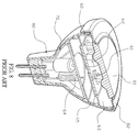
- a conventional reflector lamp includes a light emitting diode (LED) 61 disposed on a light emitting diode (LED) unit 60.
- the LED unit 60 is also arranged with a driving electronic 62 and is connected to a heat conducting portion 63 for heat dissipation.
- the LED unit 60 is further connected to a LED driver 64 and the LED driver 64 is fastened on a driver's heat dissipation portion 65 so as to dissipate heat generated. All the components mentioned above are mounted and positioned in a clamp 70 and then is set into a housing 80.
- a lens unit 81 and a front cover 82 are covered over an opening of the housing 60.
- Both the LED unit 60 and the LED driver 64 are disc-like circuit boards being disposed with a lot of electronics. Thus they have larger volume and occupy more space. Therefore the space of the housing 80 needs to be increased in order to receive the LED unit 60 and the LED driver 64. The total volume of the device is too large.
- the LED 61 and the driving electronic 62 are assembled on the same LED unit 60. While in use, the LED 61 generates a lot of heat that is directly conducted to the driving electronic 62. Thus the driving electronic 62 is easy to get damaged due to overheat.
- the LED unit 60 also has bad heat dissipation.
- the reflector lamp includes an integrally formed aluminum shade disposed with a plurality of heat dissipation fins, a round plate, a reflector installed on top of the shade, a housing disposed with inclined locking blocks and stopping strips, and an electronic device.
- the shade includes a heat dissipation channel communicating an inner side and an outer side thereof, a circular groove disposed close to the bottom end thereof, at least one stopping slot arranged axially and a mounting portion close to the top end thereof.
- An outer edge of the round plate is tightly riveted onto the mounting portion of the shade and a LED light is disposed on a front surface of the round plate.
- the reflector is installed on top of the shade. A plurality of inclined locking blocks and a plurality of stopping strips are projected from a surface of the housing.
- the housing is mounted into and fixed on the shade by the stopping strip inserted into the stopping slot and the inclined locking blocks locked into the circular groove of the shade. And the shade is only in contact with the housing at the inclined locking blocks.
- the electronic device is formed by a main circuit board and at least one secondary circuit board while the secondary circuit board is disposed on the main circuit board perpendicularly. Thus the electronic device is able to be mounted in the housing and used to control the LED light.
- external threads are formed on the heat dissipation fins and are around a top end of the shade while the reflector is positioned by a fixing ring.
- the fixing ring is disposed with internal threads on an inner edge thereof.
- the fixing ring is fastened on the heat dissipation fins by the internal threads engaged with the external threads.
- An adhesive sealant is filled between the round plate and the LED light.
- At least one slot is arranged at the main circuit board of the main circuit board.
- a plurality of electric contacts is disposed projectingly on a surface of the housing while the electronic device is connected to the electric contacts.
- An adhesive sealant is filled inside the housing.
- the electronic device is connected to a protective capacitor.
- One end of the protective capacitor and the electronic device are conducted to each other while the other end of the protective capacitor is connected to a wire.
- the wire is clipped between the housing and the shade.
- the protective capacitor conducts the high voltage current to the shade to form a test loop, without passing the LED light.
- the protective capacitor prevents the high voltage current from flowing through the LED light, working as high voltage shielding.
- the electronic device is connected to a magnetic reluctance that eliminates noises.
- the space in the housing is filled with the adhesive sealant for covering and positioning the electronic device.
- the heat dissipation of the electronic device is also improved by heat conduction of the adhesive sealant.
- sulfuration of the electronic device is also eliminated due to vacuum state formed by the adhesive sealant.
- a plurality of heat dissipation fins is arranged circularly around the tubular shade.
- the heat dissipation of the shade is further improved by the heat dissipation channel that is communicating an inner side and an outer side of the shade.
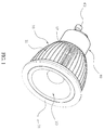
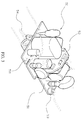
- an energy efficient high intensity reflector lamp of the present invention includes a shade 10, a round plate 20, a reflector 30, a housing 40, and an electronic device 50.
- the shade 10 is integrally formed and made from aluminum.
- a plurality of heat dissipation fins 11 is arranged circularly around the tubular shade 10 and a heat dissipation channel 12 communicating an inner side and an outer side of the shade10 is disposed circularly around the tubular shade 10.
- the heat dissipation effect of the shade 10 is increased by the heat dissipation fins 11 and the heat dissipation channel 12.
- External threads 111 are formed on the heat dissipation fins 11 and are around a top end of the shade 10.
- a circular groove 13 is mounted inside the shade 10, close to the bottom end of the shade 10 while at least one stopping slot 14 is axially arranged in the shade 10.
- a mounting portion 15 is formed adjacent to the top end of the shade 10.
- An outer edge of the round plate 20 is tightly riveted onto the mounting portion 15 of the shade 10 and a LED light 21 is disposed on a front surface of the round plate 20.
- An adhesive sealant 22 is arranged between the round plate 20 and the LED light 21 to fill pores therebetween and enhance heat conduction and dissipation.
- the reflector 30 is installed on top of the shade 10 so that light from the LED light 21 is converged and emitted out.
- a fixing ring 31 is used to position the reflector 30 and is disposed with internal threads 311 on an inner edge thereof.
- the internal threads 311 of the fixing ring 31 are engaged with the external threads 111 of the heat dissipation fins 11.
- a plurality of inclined locking blocks 41 and a plurality of stopping strips 42 are projected from a surface of the housing 40. After the housing 40 being mounted into the shade 10, the stopping strip 42 is inserted into the stopping slot 14 for preventing the shade 10 and the housing 40 from rotating.
- the inclined locking blocks 41 are pressed and locked into the circular groove 13 of the shade 10. Thus the shade 10 is only in contact with the housing 40 at the inclined locking blocks 41 so as to block heat conduction effectively.
- a plurality of electric contacts 43 is disposed projectingly on the surface of the housing 40.
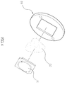
- the electronic device 50 having a main circuit board 51 and at least one secondary circuit board 52, is connected to the electric contacts 43. There is at least one slot 511 on the main circuit board 51 for providing electrical isolation.
- the secondary circuit board 52 is arranged at the main circuit board 51 perpendicularly so as to reduce the volume of the electronic device 50.
- the electronic device 50 can be mounted in the housing 40 for control of the LED light 21.
- An inner space of the housing 40 is filled with an adhesive sealant 44 and the adhesive sealant 44 is used for positioning and improving heat dissipation of the electronic device 50.
- the electronic device 50 is in vacuum insulation due to the adhesive sealant 44.
- capacitor electrolyte is unable to evaporate and sulfuration of the electronic device 50 will not occur. Therefore the service life is extended.
- the structure mentioned above not only reduces overall volume but also improves heat dissipation.
- the electronic device 50 is connected to the electric contacts 43 of the housing 40. Due to perpendicular design of the main circuit board 51 to the secondary circuit board 52, the volume of the electronic device 50 is reduced and is able to be mounted into the housing 40 easily. Then the electronic device 50 is vacuum sealed by the adhesive sealant 44 filled in the housing 40. Thus the electronic device 50 is not only fixed firmly, the heat dissipation thereof is effectively improved and the sulfuration is minimized. Next the housing is arranged into the shade 10. The rotation of both the housing 40 and the shade 10 is prevented by the stopping strips 42 of the housing 40 and the stopping slot 14 of the shade 10.
- the housing 40 and the shade 10 are in a partial contact and are fixed.
- the electronic device 50 is electrically connected to the LED light 21 of the round plate 20.
- the electrical contact 43 and the LED light 21 are electrically connected and the LED light 21 is controlled by the electronic device 50.
- the round plate 20 is fixed on the mounting portion 15 of the shade 10 by rivets.
- the reflector 30 is arranged in front of the LED light 21 in the shade 10 and is fixed by the internal threads 311 of the reflector 30 engaged with the external threads 111 of the heat dissipation fins 11. Thus light from the LED light 21 is concentrated and emitted.
- the structure mentioned above has following advantages: (1) The secondary circuit board 52 of the electronic device 50 is disposed on the main circuit board 51 in the direction perpendicular to the main circuit board 51. Thus the volume of electronic device 50 is reduced and is able to be mounted into the housing smoothly. The overall volume of the reflector lamp is decreased. (2) After receiving the electronic device 50, the housing is filled with the adhesive sealant 44 so as to cover and position the electronic device 50. Moreover, the heat dissipation of the electronic device 50 is enhanced due to heat conduction of the adhesive sealant 44. The sulfuration of the electronic device 50 is also minimized due to the vacuum state formed by the adhesive sealant 44. (3) The housing 40 is assembled with the shade 10 by the inclined locking blocks 41 being pressed and locked into the circular groove 13.
- the round plate 20 is riveted and fixed on the mounting portion 15 of the shade 10.
- the internal threads 311 of the reflector 30 are engaged with the external threads 111 of the heat dissipation fins 11 of the shade 10.
- the assembly is fast and non-contact.
- the value added is increased.
- the rotation of both the housing 40 and the shade 10 is prevented by the stopping strips 42 of the housing 40 connected to the stopping slot 14 of the shade 10.
- the housing 40 and the shade 10 are in a partial contact by the inclined locking blocks 41 of the housing 40 being pressed and locked into the circular groove 13 of the shade 10.
- the electronic device 50 will not be affected by high temperature of the end with the LED light 21 and having higher durability.
- the tubular shade 10 is integrally formed, made from aluminum and having a plurality of heat dissipation fins 11 therearound. Air flows through the space between the hollowed-out heat dissipation fins 11 so as to dissipate heat more effectively. Moreover, the heat dissipation of the shade 10 is further improved by the heat dissipation channel 12 that is communicating an inner side and an outer side of the shade 10. (6) The adhesive sealant 22 between the round plate 20 and the LED light 21 fills pores therebetween to improve heat conduction and dissipation therebetween.
- the electronic device 50 is connected to a magnetic reluctance 53 that eliminates noises.
- the magnetic reluctance 53 noises of the current flowing from the electric contact 43 and the electronic device 50 are filtered and eliminated so as to improve the stability in use.
- the LED light 21 is fixed on the round plate 20 with high thermal conductivity so that the working temperature of the LED light 21 is significantly decreased. Once the insulation strength is not enough, high voltage current easily enables a spark jumps from the LED light 21 to the shape 10 and this lead to damages of the LED light 21 while performing high voltage insulation test The lamp is also unable to pass the high voltage test.
- the electronic device 50 is connected to a protective capacitor 54.
- One end of the protective capacitor 54 and the electronic device 50 are conducted to each other while the other end of the protective capacitor 54 is connected to a wire 541.
- the wire 541 is clipped between the housing 40 and the shade 10.
- the capacitance of the protective capacitor 54 is at least five times than larger the total capacitance of the electronic device 50.
- the capacitor 54 is an open circuit and has no effect on use and control of the LED light 21.
- the protective capacitor 54 conducts the high voltage current to the shade 10 to form a test loop, without passing the LED light 21.
- the protective capacitor 54 prevents the high voltage current from flowing through the LED light 21, working as high voltage shielding.
- the LED light 21 is protected by the protective capacitor 54 and the safety requirements are met.
Landscapes
- Engineering & Computer Science (AREA)
- General Engineering & Computer Science (AREA)
- Microelectronics & Electronic Packaging (AREA)
- Physics & Mathematics (AREA)
- Optics & Photonics (AREA)
- Arrangement Of Elements, Cooling, Sealing, Or The Like Of Lighting Devices (AREA)
- Non-Portable Lighting Devices Or Systems Thereof (AREA)
Claims (8)
- Energieeffiziente Hochintensitäts-Reflektorlampe umfassend:einen Lampenschirm (10), der röhrenförmig, integral geformt und aus Aluminium gefertigt ist, wobei der Lamperischirm mit einer Vielzahl von Wärmedissipationsrippen (11) um diesen herum ausgebildet ist und einen Wärmedissipationskanal (12), über den eine Innenseite und eine Außenseite des Schirms miteinander kommunizieren, eine ringförmige Nut (13), die nahe seinem Boden angeordnet ist, mindestens einen Stoppschlitz (14), der axial angeordnet ist, und ein Montageteil (15) aufweist, das nahe seinem oberen Ende ausgebildet ist,eine runde Platte (20), die fest auf das Montageteil (15) des Lampenschirms genietet ist, wobei eine LED-Leuchte (21) an einer Vorderfläche der runden Platte (20) angeordnet ist,einen Reflektor (30), der an der Oberseite des Lampenschirms (10) installiert ist, sodass Licht von der LED-Leuchte konvergiert und emittiert wird,ein Gehäuse (40), das eine Vielzahl von geneigten Verriegelungsblöcken (41) und eine Vielzahl von Stoppstreifen (42) umfasst, die von einer Fläche desselben abstehen, wobei das Gehäuse (20) in den Lampenschirm (10) montiert ist und der Stoppstreifen (42) in den Stoppschlitz (14) eingeführt ist, um den Lampenschirm und das Gehäuse am Rotieren zu hindern, wobei die geneigten Verriegelungsblöcke (42) in der kreisförmigen Nut (13) des Lampenschirms verriegelt sind, sodass zur effektiven Vermeidung von Wärmeleistung der Lamperischirm nur an den geneigten Verriegelungsblöcken mit dem Gehäuse in Kontakt steht, undeine elektronische Vorrichtung (50), die eine Hauptleiterplatte (51) und mindestens eine Sekundarleiterplatte (52) aufweist, wobei die Sekundärleiterplatte auf der Haupti:eiterplatte senkrecht angeordnet ist, um das Volumen der elektronischen Vorrichtung zu verringern, wobei somit die elektronische Vorrichtung (50) in dem Gehäuse (40) montiert ist und dazu verwendet wird, die LED-Leuchte (21) zu kontrollieren, und wobei die elektronische Vorrichtung nicht nur ein reduziertes Volumen aufweiset, sondern ebenfalls eine verbesserte Wärmedissipation bereitstellt.
- Vorrichtung nach Anspruch 1, bei der Außengewinde (111) an den Wärmedissipationsrippen und um ein oberes Ende des Lampenschirms (10) herum ausgebildet sind, während der Reflektor durch einen Fixierung (31) positioniert ist, wobei der Fixierring mit Innengewinden (311) an seinem inneren Rand ausgebildet ist, wobei somit der Fixierring durch das Verzahnen der Innengewinde mit den Außengewinde auf den Wärmedissipationsrippen befestigt wird.
- Vorrichtung nach Anspruch 1, bei der ein Klebedichtmittel (22) zwischen der runden Platte (20) und der LED-Leuchte (21) angeordnet ist, um dazwischen befindliche Poren zu füllen und so die Wärmeleitung und Wärmedissipation zu verbessern.
- Vorrichtung nach Anspruch 1, bei der mindestens ein Schlitz (511) an der Hauptleiterplatte (51) angeordnet ist und wobei der Schlitz elektrische Isolation bereitstellt.
- Vorrichtung nach Anspruch 1, bei der eine Vielzahl von elektrischen Kontakten (43) von einer Oberfläche des Gehäuses hervor steht, während die elektronische Vorrichtung (50) mit den elektrischen Kontakten verbunden ist.
- Vorrichtung nach Anspruch 1, bei der ein Klebedichtmittel (44) in das Gehäuse gefüllt ist und wobei das Klebedichtmittel dazu verwendet wird, die elektronische Vorrichtung (50) zu positionieren und Wärme der elektronischen Vorrichtung abzuleiten.
- Vorrichtung nach Anspruch 1, bei der die elektronische Vorrichtung (50) mit einem Schutzkondensator (54) verbunden ist, wobei ein Anschluss des Schutzkondensators und die elektrische Vorrichtung miteinander verbunden sind, während der andere Anschluss des Schutzkondensators mit einem Draht (541) verbunden ist, wobei der Draht zwischen dem Gehäuse und dem Lampenschirm verklemmt ist, wobei der Schutzkondensator einen Hochspannungsstrom an den Lamperischirm (10) leitet, um eine Testschleife zu bilden ohne an der LED-Leuchte (21) vorbeizukommen, und wobei der Schutzkondensator als ein Hochspannungsschutz wirkt, um zu vermeiden, dass der Hochspannungsstrom durch die LED-Leuchte fließt.
- Vorrichtung nach Anspruch 1, bei der die elektronische Vorrichtung mit einem magnetischen Widerstand (53) verbunden ist, der Geräusche eliminiert.
Priority Applications (2)
| Application Number | Priority Date | Filing Date | Title |
|---|---|---|---|
| EP14156253.8A EP2910852B1 (de) | 2014-02-21 | 2014-02-21 | Energieeffiziente Reflektorlampe mit hoher Intensität |
| DK14156253.8T DK2910852T3 (en) | 2014-02-21 | 2014-02-21 | Energy efficient high intensity reflector lamp. |
Applications Claiming Priority (1)
| Application Number | Priority Date | Filing Date | Title |
|---|---|---|---|
| EP14156253.8A EP2910852B1 (de) | 2014-02-21 | 2014-02-21 | Energieeffiziente Reflektorlampe mit hoher Intensität |
Publications (2)
| Publication Number | Publication Date |
|---|---|
| EP2910852A1 EP2910852A1 (de) | 2015-08-26 |
| EP2910852B1 true EP2910852B1 (de) | 2016-07-20 |
Family
ID=50190198
Family Applications (1)
| Application Number | Title | Priority Date | Filing Date |
|---|---|---|---|
| EP14156253.8A Not-in-force EP2910852B1 (de) | 2014-02-21 | 2014-02-21 | Energieeffiziente Reflektorlampe mit hoher Intensität |
Country Status (2)
| Country | Link |
|---|---|
| EP (1) | EP2910852B1 (de) |
| DK (1) | DK2910852T3 (de) |
Families Citing this family (1)
| Publication number | Priority date | Publication date | Assignee | Title |
|---|---|---|---|---|
| TWI586918B (zh) * | 2015-11-20 | 2017-06-11 | LED explosion-proof lamp cover |
Family Cites Families (5)
| Publication number | Priority date | Publication date | Assignee | Title |
|---|---|---|---|---|
| TWM362926U (en) * | 2008-12-29 | 2009-08-11 | Cooler Master Co Ltd | LED lamp component |
| WO2010107781A2 (en) * | 2009-03-16 | 2010-09-23 | Molex Incorporated | Light module |
| CN102667332A (zh) * | 2009-12-03 | 2012-09-12 | 迪斯普拉斯有限责任公司 | Led灯制造方法,由此方法制造的led灯及用于此灯的散热器 |
| EP2748513B1 (de) * | 2011-08-26 | 2017-02-08 | LG Innotek Co., Ltd. | Beleuchtungsvorrichtung |
| US8419225B2 (en) * | 2011-09-19 | 2013-04-16 | Osram Sylvania Inc. | Modular light emitting diode (LED) lamp |
-
2014
- 2014-02-21 EP EP14156253.8A patent/EP2910852B1/de not_active Not-in-force
- 2014-02-21 DK DK14156253.8T patent/DK2910852T3/en active
Also Published As
| Publication number | Publication date |
|---|---|
| EP2910852A1 (de) | 2015-08-26 |
| DK2910852T3 (en) | 2016-11-14 |
Similar Documents
| Publication | Publication Date | Title |
|---|---|---|
| EP2397753B1 (de) | LED-Lampe und Wärmesenke davon mit einem Wundenheizrohr | |
| EP2163808B1 (de) | Beleuchtungsvorrichtung | |
| HK1207413A1 (en) | Light emitting diode bulb with central axis bidirectional convection heat dissipation structure | |
| US20110205741A1 (en) | Lighting equipment | |
| JP2000183406A (ja) | 発光ダイオード | |
| EP2722587A1 (de) | Sensorbeleuchtungsvorrichtung | |
| JP2015220034A (ja) | Ledモジュール及びこれを備えた車両用灯具 | |
| JP5636923B2 (ja) | ランプ | |
| CN203757500U (zh) | 省电高亮度射灯结构 | |
| KR100966599B1 (ko) | 전구형 led램프 방열구조 | |
| JP2000208177A (ja) | 電気接続箱の放熱構造 | |
| EP2228598A1 (de) | LED-Straßenlampenhalterungsstruktur | |
| US8632220B2 (en) | LED street lamp and a street lamp fixing device | |
| US8258683B2 (en) | Insulation reinforcing light bulb | |
| EP2910852A1 (de) | Energieeffiziente Reflektorlampe mit hoher Intensität | |
| EP2837880B1 (de) | Isolierter und strahlender kautschukformartikel | |
| JP2014120544A (ja) | 発光装置 | |
| KR20130025718A (ko) | 엘이디 램프 | |
| CN102588757A (zh) | 灯具 | |
| WO2019042360A1 (en) | LED LAMP | |
| KR101803002B1 (ko) | 방열구조를 갖는 led 램프 | |
| KR101262661B1 (ko) | 방수형 항공등화 모듈 | |
| KR102404718B1 (ko) | 방열장치 | |
| CN212456687U (zh) | 一种具有相变导热管散热装置的大功率led车灯 | |
| KR101175754B1 (ko) | 발광 장치 |
Legal Events
| Date | Code | Title | Description |
|---|---|---|---|
| PUAI | Public reference made under article 153(3) epc to a published international application that has entered the european phase |
Free format text: ORIGINAL CODE: 0009012 |
|
| 17P | Request for examination filed |
Effective date: 20141202 |
|
| AK | Designated contracting states |
Kind code of ref document: A1 Designated state(s): AL AT BE BG CH CY CZ DE DK EE ES FI FR GB GR HR HU IE IS IT LI LT LU LV MC MK MT NL NO PL PT RO RS SE SI SK SM TR |
|
| AX | Request for extension of the european patent |
Extension state: BA ME |
|
| RIC1 | Information provided on ipc code assigned before grant |
Ipc: F21V 17/12 20060101ALN20151030BHEP Ipc: F21V 23/00 20150101ALI20151030BHEP Ipc: F21K 99/00 20100101ALI20151030BHEP Ipc: F21V 29/00 20150101AFI20151030BHEP Ipc: F21V 17/10 20060101ALI20151030BHEP Ipc: F21V 17/16 20060101ALI20151030BHEP Ipc: F21Y 101/02 20060101ALN20151030BHEP |
|
| GRAP | Despatch of communication of intention to grant a patent |
Free format text: ORIGINAL CODE: EPIDOSNIGR1 |
|
| RAP1 | Party data changed (applicant data changed or rights of an application transferred) |
Owner name: CHAO, WEN-HSIN |
|
| RIN1 | Information on inventor provided before grant (corrected) |
Inventor name: CHAO, WEN-HSIN |
|
| INTG | Intention to grant announced |
Effective date: 20160107 |
|
| GRAS | Grant fee paid |
Free format text: ORIGINAL CODE: EPIDOSNIGR3 |
|
| GRAA | (expected) grant |
Free format text: ORIGINAL CODE: 0009210 |
|
| AK | Designated contracting states |
Kind code of ref document: B1 Designated state(s): AL AT BE BG CH CY CZ DE DK EE ES FI FR GB GR HR HU IE IS IT LI LT LU LV MC MK MT NL NO PL PT RO RS SE SI SK SM TR |
|
| REG | Reference to a national code |
Ref country code: GB Ref legal event code: FG4D |
|
| RIC1 | Information provided on ipc code assigned before grant |
Ipc: F21V 17/10 20060101ALI20160615BHEP Ipc: F21V 17/12 20060101ALN20160615BHEP Ipc: F21Y 115/10 20160101ALN20160615BHEP Ipc: F21V 23/00 20150101ALI20160615BHEP Ipc: F21K 99/00 20160101ALI20160615BHEP Ipc: F21V 29/00 20150101AFI20160615BHEP Ipc: F21V 17/16 20060101ALI20160615BHEP |
|
| REG | Reference to a national code |
Ref country code: CH Ref legal event code: EP |
|
| REG | Reference to a national code |
Ref country code: IE Ref legal event code: FG4D |
|
| REG | Reference to a national code |
Ref country code: AT Ref legal event code: REF Ref document number: 814420 Country of ref document: AT Kind code of ref document: T Effective date: 20160815 |
|
| REG | Reference to a national code |
Ref country code: DE Ref legal event code: R096 Ref document number: 602014002705 Country of ref document: DE |
|
| REG | Reference to a national code |
Ref country code: CH Ref legal event code: NV Representative=s name: LANGPATENT ANWALTSKANZLEI, CH |
|
| REG | Reference to a national code |
Ref country code: SE Ref legal event code: TRGR |
|
| REG | Reference to a national code |
Ref country code: LT Ref legal event code: MG4D |
|
| REG | Reference to a national code |
Ref country code: DK Ref legal event code: T3 Effective date: 20161110 |
|
| REG | Reference to a national code |
Ref country code: CH Ref legal event code: PCAR Free format text: NEW ADDRESS: C/O CHRISTIAN LANG TAEAETSCHESTRASSE 38 POSTFACH 454, 3914 BLATTEN B. NATERS (CH) |
|
| REG | Reference to a national code |
Ref country code: NL Ref legal event code: MP Effective date: 20160720 |
|
| REG | Reference to a national code |
Ref country code: NO Ref legal event code: T2 Effective date: 20160720 |
|
| REG | Reference to a national code |
Ref country code: AT Ref legal event code: MK05 Ref document number: 814420 Country of ref document: AT Kind code of ref document: T Effective date: 20160720 |
|
| PG25 | Lapsed in a contracting state [announced via postgrant information from national office to epo] |
Ref country code: LT Free format text: LAPSE BECAUSE OF FAILURE TO SUBMIT A TRANSLATION OF THE DESCRIPTION OR TO PAY THE FEE WITHIN THE PRESCRIBED TIME-LIMIT Effective date: 20160720 Ref country code: IT Free format text: LAPSE BECAUSE OF FAILURE TO SUBMIT A TRANSLATION OF THE DESCRIPTION OR TO PAY THE FEE WITHIN THE PRESCRIBED TIME-LIMIT Effective date: 20160720 Ref country code: HR Free format text: LAPSE BECAUSE OF FAILURE TO SUBMIT A TRANSLATION OF THE DESCRIPTION OR TO PAY THE FEE WITHIN THE PRESCRIBED TIME-LIMIT Effective date: 20160720 Ref country code: IS Free format text: LAPSE BECAUSE OF FAILURE TO SUBMIT A TRANSLATION OF THE DESCRIPTION OR TO PAY THE FEE WITHIN THE PRESCRIBED TIME-LIMIT Effective date: 20161120 Ref country code: RS Free format text: LAPSE BECAUSE OF FAILURE TO SUBMIT A TRANSLATION OF THE DESCRIPTION OR TO PAY THE FEE WITHIN THE PRESCRIBED TIME-LIMIT Effective date: 20160720 Ref country code: NL Free format text: LAPSE BECAUSE OF FAILURE TO SUBMIT A TRANSLATION OF THE DESCRIPTION OR TO PAY THE FEE WITHIN THE PRESCRIBED TIME-LIMIT Effective date: 20160720 |
|
| PG25 | Lapsed in a contracting state [announced via postgrant information from national office to epo] |
Ref country code: GR Free format text: LAPSE BECAUSE OF FAILURE TO SUBMIT A TRANSLATION OF THE DESCRIPTION OR TO PAY THE FEE WITHIN THE PRESCRIBED TIME-LIMIT Effective date: 20161021 Ref country code: BE Free format text: LAPSE BECAUSE OF FAILURE TO SUBMIT A TRANSLATION OF THE DESCRIPTION OR TO PAY THE FEE WITHIN THE PRESCRIBED TIME-LIMIT Effective date: 20160720 Ref country code: LV Free format text: LAPSE BECAUSE OF FAILURE TO SUBMIT A TRANSLATION OF THE DESCRIPTION OR TO PAY THE FEE WITHIN THE PRESCRIBED TIME-LIMIT Effective date: 20160720 Ref country code: PT Free format text: LAPSE BECAUSE OF FAILURE TO SUBMIT A TRANSLATION OF THE DESCRIPTION OR TO PAY THE FEE WITHIN THE PRESCRIBED TIME-LIMIT Effective date: 20161121 Ref country code: AT Free format text: LAPSE BECAUSE OF FAILURE TO SUBMIT A TRANSLATION OF THE DESCRIPTION OR TO PAY THE FEE WITHIN THE PRESCRIBED TIME-LIMIT Effective date: 20160720 Ref country code: ES Free format text: LAPSE BECAUSE OF FAILURE TO SUBMIT A TRANSLATION OF THE DESCRIPTION OR TO PAY THE FEE WITHIN THE PRESCRIBED TIME-LIMIT Effective date: 20160720 Ref country code: PL Free format text: LAPSE BECAUSE OF FAILURE TO SUBMIT A TRANSLATION OF THE DESCRIPTION OR TO PAY THE FEE WITHIN THE PRESCRIBED TIME-LIMIT Effective date: 20160720 |
|
| REG | Reference to a national code |
Ref country code: DE Ref legal event code: R097 Ref document number: 602014002705 Country of ref document: DE |
|
| PG25 | Lapsed in a contracting state [announced via postgrant information from national office to epo] |
Ref country code: EE Free format text: LAPSE BECAUSE OF FAILURE TO SUBMIT A TRANSLATION OF THE DESCRIPTION OR TO PAY THE FEE WITHIN THE PRESCRIBED TIME-LIMIT Effective date: 20160720 Ref country code: RO Free format text: LAPSE BECAUSE OF FAILURE TO SUBMIT A TRANSLATION OF THE DESCRIPTION OR TO PAY THE FEE WITHIN THE PRESCRIBED TIME-LIMIT Effective date: 20160720 |
|
| PLBE | No opposition filed within time limit |
Free format text: ORIGINAL CODE: 0009261 |
|
| STAA | Information on the status of an ep patent application or granted ep patent |
Free format text: STATUS: NO OPPOSITION FILED WITHIN TIME LIMIT |
|
| PG25 | Lapsed in a contracting state [announced via postgrant information from national office to epo] |
Ref country code: CZ Free format text: LAPSE BECAUSE OF FAILURE TO SUBMIT A TRANSLATION OF THE DESCRIPTION OR TO PAY THE FEE WITHIN THE PRESCRIBED TIME-LIMIT Effective date: 20160720 Ref country code: SK Free format text: LAPSE BECAUSE OF FAILURE TO SUBMIT A TRANSLATION OF THE DESCRIPTION OR TO PAY THE FEE WITHIN THE PRESCRIBED TIME-LIMIT Effective date: 20160720 Ref country code: SM Free format text: LAPSE BECAUSE OF FAILURE TO SUBMIT A TRANSLATION OF THE DESCRIPTION OR TO PAY THE FEE WITHIN THE PRESCRIBED TIME-LIMIT Effective date: 20160720 Ref country code: BG Free format text: LAPSE BECAUSE OF FAILURE TO SUBMIT A TRANSLATION OF THE DESCRIPTION OR TO PAY THE FEE WITHIN THE PRESCRIBED TIME-LIMIT Effective date: 20161020 |
|
| 26N | No opposition filed |
Effective date: 20170421 |
|
| PG25 | Lapsed in a contracting state [announced via postgrant information from national office to epo] |
Ref country code: SI Free format text: LAPSE BECAUSE OF FAILURE TO SUBMIT A TRANSLATION OF THE DESCRIPTION OR TO PAY THE FEE WITHIN THE PRESCRIBED TIME-LIMIT Effective date: 20160720 |
|
| PG25 | Lapsed in a contracting state [announced via postgrant information from national office to epo] |
Ref country code: MC Free format text: LAPSE BECAUSE OF FAILURE TO SUBMIT A TRANSLATION OF THE DESCRIPTION OR TO PAY THE FEE WITHIN THE PRESCRIBED TIME-LIMIT Effective date: 20160720 |
|
| REG | Reference to a national code |
Ref country code: IE Ref legal event code: MM4A |
|
| REG | Reference to a national code |
Ref country code: FR Ref legal event code: ST Effective date: 20171031 |
|
| PG25 | Lapsed in a contracting state [announced via postgrant information from national office to epo] |
Ref country code: LU Free format text: LAPSE BECAUSE OF NON-PAYMENT OF DUE FEES Effective date: 20170221 |
|
| PG25 | Lapsed in a contracting state [announced via postgrant information from national office to epo] |
Ref country code: FR Free format text: LAPSE BECAUSE OF NON-PAYMENT OF DUE FEES Effective date: 20170228 |
|
| PG25 | Lapsed in a contracting state [announced via postgrant information from national office to epo] |
Ref country code: IE Free format text: LAPSE BECAUSE OF NON-PAYMENT OF DUE FEES Effective date: 20170221 |
|
| PGFP | Annual fee paid to national office [announced via postgrant information from national office to epo] |
Ref country code: DK Payment date: 20180221 Year of fee payment: 5 Ref country code: DE Payment date: 20180221 Year of fee payment: 5 Ref country code: NO Payment date: 20180221 Year of fee payment: 5 Ref country code: FI Payment date: 20180216 Year of fee payment: 5 |
|
| PGFP | Annual fee paid to national office [announced via postgrant information from national office to epo] |
Ref country code: SE Payment date: 20180222 Year of fee payment: 5 |
|
| PGFP | Annual fee paid to national office [announced via postgrant information from national office to epo] |
Ref country code: CH Payment date: 20180530 Year of fee payment: 5 |
|
| PG25 | Lapsed in a contracting state [announced via postgrant information from national office to epo] |
Ref country code: MT Free format text: LAPSE BECAUSE OF NON-PAYMENT OF DUE FEES Effective date: 20170221 |
|
| GBPC | Gb: european patent ceased through non-payment of renewal fee |
Effective date: 20180221 |
|
| PG25 | Lapsed in a contracting state [announced via postgrant information from national office to epo] |
Ref country code: AL Free format text: LAPSE BECAUSE OF FAILURE TO SUBMIT A TRANSLATION OF THE DESCRIPTION OR TO PAY THE FEE WITHIN THE PRESCRIBED TIME-LIMIT Effective date: 20160720 |
|
| PG25 | Lapsed in a contracting state [announced via postgrant information from national office to epo] |
Ref country code: GB Free format text: LAPSE BECAUSE OF NON-PAYMENT OF DUE FEES Effective date: 20180221 |
|
| PG25 | Lapsed in a contracting state [announced via postgrant information from national office to epo] |
Ref country code: HU Free format text: LAPSE BECAUSE OF FAILURE TO SUBMIT A TRANSLATION OF THE DESCRIPTION OR TO PAY THE FEE WITHIN THE PRESCRIBED TIME-LIMIT; INVALID AB INITIO Effective date: 20140221 |
|
| REG | Reference to a national code |
Ref country code: DE Ref legal event code: R119 Ref document number: 602014002705 Country of ref document: DE |
|
| REG | Reference to a national code |
Ref country code: DK Ref legal event code: EBP Effective date: 20190228 Ref country code: NO Ref legal event code: MMEP |
|
| REG | Reference to a national code |
Ref country code: CH Ref legal event code: PL |
|
| REG | Reference to a national code |
Ref country code: SE Ref legal event code: EUG |
|
| PG25 | Lapsed in a contracting state [announced via postgrant information from national office to epo] |
Ref country code: SE Free format text: LAPSE BECAUSE OF NON-PAYMENT OF DUE FEES Effective date: 20190222 Ref country code: CY Free format text: LAPSE BECAUSE OF FAILURE TO SUBMIT A TRANSLATION OF THE DESCRIPTION OR TO PAY THE FEE WITHIN THE PRESCRIBED TIME-LIMIT Effective date: 20160720 Ref country code: FI Free format text: LAPSE BECAUSE OF NON-PAYMENT OF DUE FEES Effective date: 20190221 Ref country code: NO Free format text: LAPSE BECAUSE OF NON-PAYMENT OF DUE FEES Effective date: 20190228 |
|
| PG25 | Lapsed in a contracting state [announced via postgrant information from national office to epo] |
Ref country code: MK Free format text: LAPSE BECAUSE OF FAILURE TO SUBMIT A TRANSLATION OF THE DESCRIPTION OR TO PAY THE FEE WITHIN THE PRESCRIBED TIME-LIMIT Effective date: 20160720 |
|
| PG25 | Lapsed in a contracting state [announced via postgrant information from national office to epo] |
Ref country code: CH Free format text: LAPSE BECAUSE OF NON-PAYMENT OF DUE FEES Effective date: 20190228 Ref country code: LI Free format text: LAPSE BECAUSE OF NON-PAYMENT OF DUE FEES Effective date: 20190228 |
|
| PG25 | Lapsed in a contracting state [announced via postgrant information from national office to epo] |
Ref country code: DK Free format text: LAPSE BECAUSE OF NON-PAYMENT OF DUE FEES Effective date: 20190228 Ref country code: DE Free format text: LAPSE BECAUSE OF NON-PAYMENT OF DUE FEES Effective date: 20190903 |
|
| PG25 | Lapsed in a contracting state [announced via postgrant information from national office to epo] |
Ref country code: TR Free format text: LAPSE BECAUSE OF FAILURE TO SUBMIT A TRANSLATION OF THE DESCRIPTION OR TO PAY THE FEE WITHIN THE PRESCRIBED TIME-LIMIT Effective date: 20160720 |